WO2012132589A1 - 被覆に扁平粉末磁性体を使用したケーブルおよびその製造方法 - Google Patents
被覆に扁平粉末磁性体を使用したケーブルおよびその製造方法 Download PDFInfo
- Publication number
- WO2012132589A1 WO2012132589A1 PCT/JP2012/053422 JP2012053422W WO2012132589A1 WO 2012132589 A1 WO2012132589 A1 WO 2012132589A1 JP 2012053422 W JP2012053422 W JP 2012053422W WO 2012132589 A1 WO2012132589 A1 WO 2012132589A1
- Authority
- WO
- WIPO (PCT)
- Prior art keywords
- magnetic
- core wire
- covering portion
- resin material
- cable
- Prior art date
- Legal status (The legal status is an assumption and is not a legal conclusion. Google has not performed a legal analysis and makes no representation as to the accuracy of the status listed.)
- Ceased
Links
Images




Classifications
-
- H—ELECTRICITY
- H01—ELECTRIC ELEMENTS
- H01B—CABLES; CONDUCTORS; INSULATORS; SELECTION OF MATERIALS FOR THEIR CONDUCTIVE, INSULATING OR DIELECTRIC PROPERTIES
- H01B13/00—Apparatus or processes specially adapted for manufacturing conductors or cables
- H01B13/06—Insulating conductors or cables
- H01B13/14—Insulating conductors or cables by extrusion
- H01B13/141—Insulating conductors or cables by extrusion of two or more insulating layers
-
- H—ELECTRICITY
- H01—ELECTRIC ELEMENTS
- H01B—CABLES; CONDUCTORS; INSULATORS; SELECTION OF MATERIALS FOR THEIR CONDUCTIVE, INSULATING OR DIELECTRIC PROPERTIES
- H01B7/00—Insulated conductors or cables characterised by their form
- H01B7/02—Disposition of insulation
- H01B7/0208—Cables with several layers of insulating material
-
- H—ELECTRICITY
- H01—ELECTRIC ELEMENTS
- H01B—CABLES; CONDUCTORS; INSULATORS; SELECTION OF MATERIALS FOR THEIR CONDUCTIVE, INSULATING OR DIELECTRIC PROPERTIES
- H01B11/00—Communication cables or conductors
- H01B11/02—Cables with twisted pairs or quads
- H01B11/06—Cables with twisted pairs or quads with means for reducing effects of electromagnetic or electrostatic disturbances, e.g. screens
- H01B11/10—Screens specially adapted for reducing interference from external sources
- H01B11/1058—Screens specially adapted for reducing interference from external sources using a coating, e.g. a loaded polymer, ink or print
- H01B11/1083—Screens specially adapted for reducing interference from external sources using a coating, e.g. a loaded polymer, ink or print the coating containing magnetic material
Definitions
- the present invention relates to a cable using a magnetic material for coating, and particularly to a cable having a thin wire diameter that can be easily covered using a flat magnetic powder as a magnetic material used for coating, and a method for manufacturing the same.
- EMC Electro-Magnetic Compatibility
- a cable described in Patent Document 1 below is known as a cable whose outer periphery is coated with a magnetic material.
- FIG. 11 is an exploded perspective view showing the structure of a cable whose outer periphery is covered with a magnetic material described in Patent Document 1.
- FIG. 11 is an exploded perspective view showing the structure of a cable whose outer periphery is covered with a magnetic material described in Patent Document 1.
- a shield layer S is provided outside the signal line W, a magnetic layer M is provided outside the shield layer S, and the outer layer O is covered. Cover.
- the magnetic layer M has a two-layer structure in which a ferrite resin layer Fe is provided on one side of the metal film SF.
- the cable whose outer periphery is covered with the magnetic material described in Patent Document 1 is covered with the magnetic material layer M on the outside of the signal line W, so that noise is suppressed and exhibits an effect on EMC and crosstalk.
- the cable whose outer periphery is coated with the magnetic body has a structure in which the shield layer S is provided outside the signal line W, the magnetic layer M is provided outside the shield layer S, and the outer cover layer O covers the cable. Therefore, there are many steps for covering, and there is a problem that the wire diameter of the cable Ca after covering becomes thick.
- the present invention solves the above-mentioned problems and provides a cable with a thin wire diameter that can be easily covered with a magnetic body and uses a flat magnetic powder for the magnetic body covering the outer periphery.
- the cable according to claim 1 is a cable in which a magnetic body is disposed on an outer peripheral portion of a core wire through which an electrical signal passes, and the core wire is covered with an insulator covering portion formed of an insulator,
- the portion is formed in a cylindrical shape, and has a spiral groove portion on the outer periphery along the length direction of the core wire, and a magnetic body covering portion formed of an insulator containing flat magnetic powder in the groove portion. It has the characteristic that it is provided integrally with the said insulator coating
- the cable according to claim 2 is characterized in that the flat magnetic powder contained in the magnetic coating portion is oriented so as to form a layer concentrically with respect to the center of the core wire.
- the cable according to claim 3 is characterized in that the magnetic susceptibility magnetic loss of the flat magnetic powder is less than 15 in the frequency band of 20 Mhz to 1 Ghz.
- the cable according to claim 4 is characterized in that the thickness of the magnetic body covering portion is 1 mm or less.
- the cable manufacturing method wherein the core wire is covered with a synthetic resin material, and the core wire covered with the synthetic resin material is covered with a magnetic material.
- the extruder of 1 forms the insulator coating
- the magnetic resin material is injected into the concave groove portion of the core wire covered with the covering portion, and the magnetic body covering portion is formed integrally with the insulator covering portion.
- the first extruder includes a first melting furnace capable of heating and melting the synthetic resin material and inserting the core wire
- the first melting furnace has a first extrusion hole through which the core wire can be inserted, and the core wire is inserted into the first melting furnace containing the heat-melted synthetic resin material,
- the first extruder forms the insulator covering portion around the core wire, and the second extruder heats and melts the magnetic resin material.
- a second melting furnace capable of inserting the core wire covered by the insulator covering portion, the second melting furnace being able to insert the core wire covered by the insulator covering portion.
- the magnetic resin material is heated and melted.
- the second extruder By inserting the core wire covered with the insulator covering portion into the second melting furnace wrapped and taking out from the second extrusion hole, the second extruder is attached to the insulator covering portion.
- the magnetic resin material is injected into the recessed groove portion of the coated core wire, and the magnetic body covering portion is formed integrally with the insulator covering portion.
- the first extrusion hole includes a concave groove processing mechanism that processes the concave groove portion into a spiral concave groove
- the concave groove processing mechanism includes the core wire.
- the core covered with the synthetic resin material is taken out from the first extruder to form the insulator covering portion having the spiral groove.
- the cable manufacturing method wherein in the second melting furnace, the magnetic resin material attached around the core wire covered with the insulator covering portion is injected into the concave groove portion. Except for the magnetic resin material, the second extrusion hole end portion of the inner wall of the second melting furnace is removed, and the magnetic body contained in the magnetic resin material is located with respect to the center of the core wire. It is characterized by being oriented so as to form layers concentrically.
- the cable manufacturing method according to claim 9 is characterized in that the depth of the concave groove portion is 1 mm or less.
- the magnetic powders are overlapped with each other and the gaps are formed as compared with the case where the granular magnetic powder is used by orienting the flat-shaped flat magnetic powder to form a layer. There is an effect that it becomes smaller and noise can be suppressed more efficiently.
- the flat magnetic powder is formed concentrically with respect to the center of the core wire. The effect that it can orientate so that it may comprise is produced.
- the core wire is covered with the insulator covering portion, and the magnetic resin material is injected into the spiral groove portion provided in the insulator covering portion so as to be integrally molded.
- the outer periphery of the core wire is covered with a synthetic resin material and a magnetic resin material by molding, thereby making it easier to manufacture than a conventional method of winding a magnetic sheet around a core wire.
- the cable can be realized by this method.
- the insulator covering portion is obtained by taking out the core wire covered with the molten synthetic resin material from the first extruder through the nozzle portion in a state where the protrusion is rotating. There is an effect that it is possible to easily process the spiral groove portion on the outer periphery.
- the eighth aspect of the present invention it is possible to remove the excess magnetic resin material from the outer peripheral surface of the insulator covering portion and form the magnetic body covering portion in the recessed groove portion by an easy method using the doctor blade method. There is an effect that it is possible.
- the flat magnetic powder is placed in the center of the core wire.
- the film can be oriented so as to form a concentric layer.
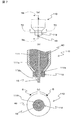
- FIG. 1 is a diagram illustrating an appearance of a cable according to the present embodiment.
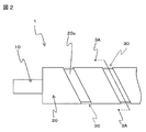
- FIG. 2 is a side view showing the cable of the present embodiment.
- the magnetic body covering portion 30 is indicated by a virtual line.
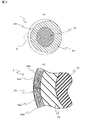
- 3 is a view showing the orientation state of the flat magnetic powder 30a
- FIG. 3 (a) is a cross-sectional view showing a cross section 3-3 of FIG. 2
- FIG. 3 (b) is a cross-sectional view of FIG. 3 (a). It is an enlarged view of the A section.
- FIG. 4 is an example of a cross-sectional SEM photograph of the magnetic body covering portion 30.
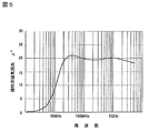
- FIG. 5 is a diagram showing the magnetic loss characteristics of the flat magnetic powder 30a.
- the cable 1 of the present embodiment includes a core wire 10 through which an electrical signal passes, an insulator covering portion 20 that is formed of an insulator and covers the core wire 10, and an insulator covering portion 20. And a magnetic body covering portion 30 disposed in a spiral shape along the outer periphery.
- the core wire 10 is formed of a conductive wire.
- the insulator covering portion 20 is formed in a cylindrical shape by a synthetic resin material 40 (see FIG. 7B) that covers the periphery of the core wire 10 and has insulating properties and flexibility. Moreover, it has the spiral groove part 20a on the outer periphery along the length direction of the core wire 10.
- the magnetic body covering portion 30 is formed of a magnetic resin material 50 (see FIG. 8B) that is an insulator containing the flat magnetic powder 30a, and is provided integrally in the recessed groove portion 20a of the insulating body covering portion 20. At the same time, it is provided flush with the outer peripheral surface of the insulator covering portion 20.
- the magnetic resin material 50 forming the magnetic body covering portion 30 contains the flat magnetic powder 30a in the insulator 30b.
- the flat magnetic powder 30a is oriented so as to be concentrically layered with respect to the center of the core wire 10.
- the flat magnetic powder 30a will be briefly described. Although the detailed description is omitted, the flat magnetic powder 30a is obtained by classifying granular magnetic powder prepared by a water atomizing method using a material containing iron as a main component, for example, permalloy (Fe—Ni alloy). And processed into a flat magnetic powder using an apparatus such as a planetary stirring ball mill.
- a material containing iron as a main component for example, permalloy (Fe—Ni alloy).
- an annealing treatment may be performed to relieve the internal stress as necessary.
- the magnetic loss magnetic loss ⁇ ′′ of the flat magnetic powder 30a is 15 or more in the frequency band of 20 Mhz to 1 Ghz.
- cover part 30 is formed in 1 mm or less.
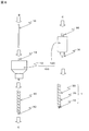
- FIG. 6 is a diagram illustrating a configuration of a manufacturing apparatus 100 that manufactures the cable 1.
- FIG. 7 is a view showing the structure of the first extruder 110
- FIG. 7 (a) is an external view of the first extruder 110
- FIG. 7 (b) is a cross section 7B of FIG. 7 (a).
- FIG. 7C is a cross-sectional view showing a cross section 7C-7C of FIG. 7A.
- FIG. 8 is a view showing the structure of the second extruder 120
- FIG. 8A is an external view of the second extruder 120
- FIG. 8B is a cross section 8B of FIG. 8A
- FIG. 8C is a cross-sectional view showing ⁇ 8B
- FIG. 8C is an enlarged view showing a portion E of FIG. 8B.
- the manufacturing apparatus 100 that manufactures the cable 1 includes a first extruder 110 that can heat and melt and extrude the synthetic resin material 40 that forms the insulator covering portion 20, and a magnetic body. And a second extruder 120 capable of heating and melting the magnetic resin material 50 forming the covering portion 30 and extruding the same.
- the flow of manufacturing the cable 1 is performed by installing the core wire 10 in the first extruder 110 and processing it, so that the insulator covering portion 20 is formed around the core wire 10. .
- the core wire 10 covered with the insulator covering portion 20 is installed and processed in the second extruder 120, so that the magnetic covering portion 30 is formed integrally with the insulator covering portion 20 in the recessed groove portion 20a.
- the cable 1 is obtained.
- FIG. 6 the figure of the manufacturing apparatus 100 which manufactures the cable 1 shown in FIG. 6 is a conceptual diagram, and the shape of the manufacturing apparatus 100 etc. are not necessarily shown in a figure.
- the first extruder 110 forms and coats the insulator covering portion 20 in a cylindrical shape around the core wire 10 with a synthetic resin material, and forms a spiral groove 20 a on the outer periphery of the insulator covering portion 20. Can do.
- the first extruder 110 includes a first melting furnace 111 that can heat and melt the synthetic resin material 40 and can insert the core wire 10.
- 111 has the 1st extrusion hole 111a which can insert the core wire 10.
- the first extruder 110 is insulated around the core wire 10 by inserting the core wire 10 into the first melting furnace 111 containing the heat-melted synthetic resin material 40 and taking it out from the first extrusion hole 111a.
- the body covering portion 20 can be formed.
- the first extrusion hole 111 a includes a groove processing mechanism 112 that processes the groove 20 a on the outer periphery of the insulator covering portion 20.
- the groove processing mechanism 112 includes a nozzle portion 112a through which the core wire 10 can be inserted.
- the nozzle portion 112a has a pleated protrusion 112b on the inner peripheral surface, and an arrow D shown in FIG. It is provided to be rotatable in the direction.
- the concave groove machining mechanism 112 rotates in a constant direction at a constant speed, and accordingly, the projection 112b provided on the inner peripheral surface of the nozzle portion 112a also rotates.
- the insulator covering portion 20 having a spiral groove portion 20a around the core wire 10 covered with the synthetic resin material 40 is taken out from the first extruder 110 through the nozzle portion 112a in a state where the protrusion 112b is rotated. Is formed. At this time, the depth of the groove 20a is 1 mm or less.
- the core wire 10 covered with the insulator covering portion 20 is formed by cooling the insulator covering portion 20 thus formed.
- the second extruder 120 injects the magnetic resin material 50 into the groove 20 a of the core wire 10 covered with the insulator covering portion 20, and forms the magnetic body covering portion 30 integrally with the insulator covering portion 20.
- the second extruder 120 can heat and melt the magnetic resin material 50 and can insert the core wire 10 covered with the insulator covering portion 20.
- a furnace 121 is provided.
- the second melting furnace 121 has a second extrusion hole 121a into which the core wire 10 covered by the insulator covering portion 20 can be inserted, and includes a magnetic resin material 50 that is heated and melted.
- the core wire 10 covered with the insulator covering portion 20 is inserted into the core 121 and taken out from the second push-out hole 121a, so that the second extruder 120 has the core wire 10 covered with the insulator covering portion 20
- the magnetic resin material 50 is injected into the recessed groove portion 20 a and the magnetic body covering portion 30 is formed integrally with the insulator covering portion 20.
- the magnetic resin material 50 adhered around the core wire 10 covered with the insulator covering portion 20 is the same as the first, except for the magnetic resin material 50 injected into the concave groove portion 20a. 2 is removed by a wiping portion 121b (second extrusion hole end portion) provided on the inner wall of the second melting furnace 121.
- the wiping portion 121b can remove the excess magnetic resin material 50.
- the wiping portion 121b can remove the excess magnetic resin material 50 by forming the same structure as the doctor blade method by setting the interval between the wiping portion 121b and the insulator covering portion 20 to a predetermined interval. It is because it is doing.
- FIG. 9 is a diagram showing an example of an apparatus using a doctor blade method.
- the doctor blade method is one of the methods used to form thin films and films.
- the apparatus using the doctor blade method is a blade BL that can adjust the thickness of a thin film or the like by moving up and down, and a container that holds slurry SL that is a material such as a thin film together with the blade BL.
- the main body BE and the base material CT which conveys the slurry SL are provided.
- the slurry SL can be stored in the container part PT formed by the main body BE and the blade BL.
- a base material CT is disposed at the bottom of the container part PT, and the base material CT moves at a constant speed in the direction of arrow F shown in FIG.
- a discharge hole GE having a predetermined gap is provided between the base CT and the blade BL and has the same width as the base CT, and the base CT moves at a constant speed in the direction of arrow F.
- the slurry SL together with the base material CT passes through the discharge hole GA and moves to the outside of the container part PT.
- the slurry SL having a certain thickness is disposed on the base material CT by passing through the discharge hole GA and moving to the outside of the container part PT. Is formed.
- the second melting furnace 121 serves as the container part PT
- the wiping part 121b serves as the blade BL
- the core wire 10 covered by the insulator covering part 20 is the base material CT.
- the distance between the wiping portion 121b and the insulator covering portion 20 is set to a predetermined interval so that the doctor blade method forms a slurry having a uniform film thickness by adjusting the position of the blade BL. It becomes possible to remove the excess magnetic resin material 50.
- the wiping portion 121b leveles the magnetic resin material 50 injected into the concave groove portion 20a, so that the magnetic resin
- the flat magnetic powder 30 a included in the material 50 is oriented so as to be concentrically layered with respect to the center of the core wire 10.
- the flat magnetic powder 30a contained in the magnetic resin material 50 is oriented so as to form a layer concentrically with respect to the center of the core wire 10 while managing the thickness of the magnetic body covering portion 30 to 1 mm or less. This is because the depth of the concave groove 20a is controlled to 1 mm or less, and the excess magnetic resin material 50 is removed by a method similar to the doctor blade method.
- FIG. 10 is an SEM photograph in which the magnetic resin material 50 is formed in a sheet shape with an apparatus utilizing the doctor blade method, and a cross section thereof is photographed.
- FIG. 10A is an SEM photograph showing a cross section when the thickness of the sheet made of the magnetic resin material 50 is thicker than 1 mm
- FIG. 10B shows the thickness of the sheet made of the magnetic resin material 50. It is a SEM photograph which photoed the section at the time of making it 1 mm or less.
- the orientation of the flat magnetic powder 30a is likely to be disturbed as shown in part G of FIG.
- the thickness of the sheet is 1 mm or less, as shown in FIG. 10B, the orientation of the flat magnetic powder 30a is not disturbed.
- the thickness of the magnetic body covering portion 30 1 mm or less by making the thickness of the magnetic body covering portion 30 1 mm or less, the orientation of the flat magnetic powder 30 a in the magnetic resin material 50 is not disturbed, and the flat magnetic powder 30 a is in the center of the core wire 10.
- the layers are oriented in a concentric manner.
- the cable 1 covered with the insulator covering portion 20 and the magnetic covering portion 30 is formed by cooling the magnetic covering portion 30 thus formed.
- the core wire 10 is covered with the insulator covering portion 20 formed of an insulator, and the flat magnetic powder 30a is contained in the recessed groove portion 20a formed on the outer periphery of the insulator covering portion 20.
- the magnetic body covering portion 30 is provided integrally with the insulator covering portion 20.
- the periphery of the core wire 10 is covered with the insulator covering portion 20 having the recessed groove portion 20a, and the magnetic body covering portion 30 containing the flat magnetic powder 30a is disposed in the recessed groove portion 20a.
- the effect of suppressing noise equal to or higher than that it is possible to form a cable with a thinner wire diameter.
- the flat magnetic powder 30 a contained in the magnetic body covering portion 30 is oriented so as to be concentrically layered with respect to the center of the core wire 10.
- the magnetic susceptibility magnetic loss ⁇ ′′ of the flat magnetic powder 30a is 15 or more in the frequency band of 20 Mhz to 1 Ghz.
- the magnetic susceptibility magnetic loss ⁇ ′′ which is a value indicating the characteristic of absorbing electromagnetic waves, is a value of 15 or more in a wide frequency range of 20 Mhz to 1 Ghz, and therefore a stable noise suppression effect in the high frequency range. The effect that can be exhibited.
- the thickness of the magnetic body covering portion 30 is formed to be 1 mm or less.
- the flat magnetic powder 30a is formed concentrically with respect to the center of the core wire 10. Can be oriented.
- the synthetic resin material 40 and the magnetic resin material 50 are made of flexible materials.
- the cable 1 has flexibility, and can be used for more various applications as compared with the case where the cable 1 does not have flexibility.
- the manufacturing method of the cable 1 of this embodiment it is possible to heat and melt and extrude the magnetic resin material 50 and the first extruder 110 that can heat and melt the synthetic resin material 40.
- Second extruder 120 The first extruder 110 covers the periphery of the core wire 10 with a synthetic resin material 40 in a cylindrical shape, and forms the insulator covering portion 20 having a spiral groove 20a on the outer periphery.
- the second extruder 120 In the manufacturing method, the magnetic resin material 50 is injected into the groove 20 a of the core wire 10 covered with the insulator covering portion 20, and the magnetic covering portion 30 is molded integrally with the insulator covering portion 20.
- the core wire 10 is covered with the insulator covering portion 20, and the magnetic resin material 50 is injected into the spiral concave groove portion 20a provided in the insulator covering portion 20 so as to be integrally molded.
- the magnetic resin material 50 is injected into the spiral concave groove portion 20a provided in the insulator covering portion 20 so as to be integrally molded.
- the first extruder 110 includes the first melting furnace 111 that can heat and melt the synthetic resin material 40 and can insert the core wire 10.
- the first melting furnace 111 has a first extrusion hole 111a through which the core wire 10 can be inserted, and the core wire 10 is inserted into the first melting furnace 111 containing the heat-melted synthetic resin material 40.
- the 1st extruder 110 shape
- the second extruder 120 includes a second melting furnace 121 that can heat and melt the magnetic resin material 50 and can insert the core wire 10 covered by the insulator covering portion 20.
- the second melting furnace 121 has a second extrusion hole 121a into which the core wire 10 covered by the insulator covering portion 20 can be inserted, and includes a magnetic resin material 50 that is heated and melted.
- the second extruder 120 has a concave portion of the core wire 10 covered with the insulator cover portion 20.
- the magnetic resin material 50 is injected into the groove portion 20 a and the magnetic body covering portion 30 is formed integrally with the insulator covering portion 20.
- the outer periphery of the core wire 10 is covered with a synthetic resin material and a magnetic resin material by molding, thereby realizing a cable with an easier manufacturing method compared to the conventional method of winding a magnetic sheet around a core wire. There is an effect that it is possible.
- the 1st extrusion hole 111a is provided with the ditch
- 10 is provided with a nozzle portion 112a through which the nozzle portion 112a can be inserted.
- the nozzle portion 112a has a ridge-like protrusion 112b on the inner peripheral surface, is rotatably provided around the core wire 10, and is in a state of rotating the protrusion 112b. It was set as the manufacturing method which forms the insulator coating
- the core wire 10 covered with the molten synthetic resin material 40 is taken out from the first extruder 110 through the nozzle portion 112a in a state in which the protrusion 112b is rotated, so that the outer periphery of the insulator covering portion 20 is spiraled.
- the concave groove portion 20a can be easily processed.
- coated part 20 in the 2nd melting furnace 121 is inject
- the flat magnetic powder 30a contained in the magnetic resin material 50 is concentrically formed with respect to the center of the core wire 10 while being removed by the wiping portion 121b of the second melting furnace 121 except for the magnetic resin material 50 that has been removed.
- coated part 30 can be formed in the recessed groove part 20a. There is an effect.
- the depth of the groove 20a is formed to 1 mm or less.
- the flat magnetic powder 30a is made to be centered on the center of the core wire 10.
- the cable and the manufacturing method thereof according to the embodiment of the present invention have been specifically described.
- the present invention is not limited to the above-described embodiment, and various modifications can be made without departing from the scope of the invention. It is possible to implement.
- the present invention can be modified as follows, and these embodiments also belong to the technical scope of the present invention.
- the magnetic body covering portion 30 is disposed in a spiral shape, but may be disposed in a lattice shape.
- the synthetic resin material 40 that forms the insulator covering portion 20 and the magnetic resin material 50 that forms the magnetic covering portion 30 are flexible materials, but are not necessarily flexible. It does not have to have sex.
- the water atomization method is used as a method for producing the flat magnetic powder 30a, but a gas atomization method, a liquid quenching method, or the like may be used.
- the wiping portion 121b is a terminal portion of the second extrusion hole 121a and the cross-sectional shape is shown as a right angle, but the excess magnetic resin material 50 is more efficiently removed.
- the angle of the cross-sectional shape may be changed, or a squeegee may be formed.
- the number of the protrusions 112b is one, but the number is increased within a range that does not impair the noise suppression effect, and the magnetic body covering portion 30 is formed in a double spiral or triple spiral. It may be a shape. Thereby, the noise suppression effect increases more because the area of the magnetic body coating
- the direction of taking out the core wire 10 covered with the insulator covering portion 20 from the first extruder 110 and the direction of taking out the cable 1 from the second extruder 120 are set downward. However, it may be taken out from the side or from above.
Landscapes
- Engineering & Computer Science (AREA)
- Manufacturing & Machinery (AREA)
- Extrusion Moulding Of Plastics Or The Like (AREA)
- Soft Magnetic Materials (AREA)
- Insulated Conductors (AREA)
- Communication Cables (AREA)
- Processes Specially Adapted For Manufacturing Cables (AREA)
Abstract
【課題】外周を容易に磁性体で被覆でき、外周を被覆する磁性体に扁平状磁性粉末を使用した線径の細いケーブルおよびその製造方法を提供する。 【解決手段】ケーブル1は、芯線10の外周部が絶縁体で形成された絶縁体被覆部20に被覆され、絶縁体被覆部20の外周には扁平状磁性粉末30aを含有する磁性体被覆部30が前記絶縁体被覆部と一体に螺旋状に設けられており、扁平状磁性粉末30aは芯線10の中心に対して同心円状に配向している。また、その製造方法は、合成樹脂材40を加熱溶融し芯線10の外周に絶縁体被覆部20を形成する第1の押出機と、磁性樹脂材50を加熱溶融し絶縁体被覆部20の外周に磁性体被覆部30を形成する第2の押出機とを備えている。
Description
本発明は、被覆に磁性体を使用したケーブルに関し、特に、被覆に用いる磁性体として扁平状磁性粉末を使用し容易に被覆できるとともに線径が細いケーブルおよびその製造方法に関するものである。
昨今、信号を送信・受信する速度が高速化するに従い、ケーブルから出入りする電磁波に対するEMC(Electro-Magnetic Compatibility、電磁両立性)や、信号間のクロストークの問題が取り上げられている。
このようなEMCやクロストークなどのノイズに関する問題を解決する為に、ノイズ抑制効果のある磁性体で外周を被覆したケーブルが求められている。
磁性体で外周を被覆されたケーブルとしては、下記の特許文献1に記載のケーブルが知られている。
以下、図11を用いて、特許文献1に記載の磁性体で外周を被覆されたケーブルについて説明する。図11は、特許文献1に記載の磁性体で外周を被覆されたケーブルの構造を示す分解斜視図である。
特許文献1に記載の磁性体で外周を被覆されたケーブルCaは、信号線Wの外側にシールド層Sを設け、シールド層Sの外側に磁性体層Mを設けて外被層Oにて被蔽する。磁性体層Mは、金属フィルムSFの片面にフェライト樹脂層Feを設けて2層構造となっている。
特許文献1に記載の磁性体で外周を被覆されたケーブルは、信号線Wの外側を磁性体層Mで被蔽することでノイズが抑制され、EMCやクロストークに対して効果を発揮する。
しかしながら、上記磁性体で外周を被覆されたケーブルは、信号線Wの外側にシールド層Sを設け、シールド層Sの外側に磁性体層Mを設けて外被層Oにて被蔽する構造としているため、被蔽するための工程が多く、被蔽後のケーブルCaの線径が太くなるという問題があった。
本発明は、上述した課題を解決して、外周を磁性体で容易に被覆でき、外周を被覆する磁性体に扁平状磁性粉末を使用した線径の細いケーブルを提供するものである。
請求項1に記載のケーブルは、電気的信号が通る芯線の外周部に磁性体が配されたケーブルにおいて、前記芯線は、絶縁体で形成された絶縁体被覆部に被覆され、前記絶縁体被覆部は円筒状に形成され前記芯線の長さ方向に沿って外周に螺旋状の凹溝部を有し、前記凹溝部内に扁平状磁性粉末を含有する絶縁体で形成された磁性体被覆部が前記絶縁体被覆部と一体に設けられている、という特徴を有する。
請求項2に記載のケーブルは、前記磁性体被覆部に含有される前記扁平状磁性粉末は、前記芯線の中心に対して同心円状に層を成すように配向している、という特徴を有する。
請求項3に記載のケーブルは、前記扁平状磁性粉末の磁性率磁気損失は、周波数帯が20Mhzから1Ghzの範囲において、15以上で変動が小さい、という特徴を有する。
請求項4に記載のケーブルは、前記磁性体被覆部の厚さを1mm以下に形成する、という特徴を有する。
請求項5に記載のケーブルの製造方法は、芯線の周囲を合成樹脂材で被覆し、前記合成樹脂材で被覆された前記芯線の周囲を磁性体で被覆するケーブルの製造方法において、前記合成樹脂材を加熱溶融して押出すことが可能な第1の押出機と、前記磁性体を含有する磁性樹脂材を加熱溶融して押出すことが可能な第2の押出機とを備え、前記第1の押出機は、前記芯線の周囲を前記合成樹脂材で円筒状に被覆するとともに外周に螺旋状の凹溝部を有する絶縁体被覆部を成形し、前記第2の押出機は、前記絶縁体被覆部で被覆された前記芯線の前記凹溝部に前記磁性樹脂材を注入し前記絶縁体被覆部と一体に磁性体被覆部を成形する、という特徴を有する。
請求項6に記載のケーブルの製造方法は、前記第1の押出機は、前記合成樹脂材を加熱し溶融することが可能であるとともに前記芯線を挿入可能な第1の溶融炉を備え、前記第1の溶融炉は前記芯線を挿通可能な第1の押出穴を有しており、加熱溶融された前記合成樹脂材を内包した前記第1の溶融炉内に、前記芯線を挿入し、前記第1の押出穴から取り出すことで、前記第1の押出機は、前記芯線の周囲に前記絶縁体被覆部を成形し、前記第2の押出機は、前記磁性樹脂材を加熱し溶融することが可能であるとともに、前記絶縁体被覆部によって被覆された前記芯線を挿入可能な第2の溶融炉を備え、前記第2の溶融炉は前記絶縁体被覆部に被覆された前記芯線を挿通可能な第2の押出穴を有しており、加熱溶融された前記磁性樹脂材を内包した前記第2の溶融炉内に、前記絶縁体被覆部によって被覆された前記芯線を挿入し前記第2の押出穴から取り出すことで、前記第2の押出機は、前記絶縁体被覆部に被覆された前記芯線の前記凹溝部に前記磁性樹脂材を注入し前記絶縁体被覆部と一体に前記磁性体被覆部を成形する、という特徴を有する。
請求項7に記載のケーブルの製造方法は、前記第1の押出穴は、前記凹溝部を螺旋状の凹溝に加工する凹溝加工機構を備えており、前記凹溝加工機構は前記芯線を挿通可能なノズル部を備え、前記ノズル部は内周面にヒダ状の突部を有し、前記芯線を中心として回転可能に設けられ、前記突部を回転させた状態の前記ノズル部を介して前記合成樹脂材に被覆された前記芯線を前記第1の押出機から取り出すことで螺旋状の前記凹溝部を有する前記絶縁体被覆部を形成する、という特徴を有する。
請求項8に記載のケーブルの製造方法は、前記第2の溶融炉内において、前記絶縁体被覆部に被覆された前記芯線の周囲に付着した前記磁性樹脂材は、前記凹溝部内に注入された前記磁性樹脂材を除いて、前記第2の溶融炉の内壁の前記第2の押出穴末端部により除去されるとともに、前記磁性樹脂材に含まれる前記磁性体は前記芯線の中心に対して同心円状に層を成すように配向する、という特徴を有する。
請求項9に記載のケーブルの製造方法は、前記凹溝部の深さを1mm以下に形成する、という特徴を有する。
請求項1の発明によれば、凹溝部を有する絶縁体被覆部で芯線の周囲を被覆し、凹溝部内に扁平状磁性粉末を含有する磁性体被覆部を配置したことで、従来のケーブと比べて同等以上のノイズを抑制する効果が得られるとともに、より線径が細いケーブルを形成することが可能となる、という効果を奏する。
請求項2の発明によれば、扁平形状の扁平状磁性粉末が層を成すように配向することで、仮に粒状の磁性粉末を用いた場合と比較して、磁性体粉末同士が重なり合い、隙間が小さくなりより効率よくノイズを抑制することが可能となる、という効果を奏する。
請求項3の発明によれば、広範囲の高周波領域において安定したノイズ抑制効果を発揮することができる、という効果を奏する。
請求項4の発明によれば、磁性体被覆部の厚さを1mm以下にすることで、磁性体被覆部を形成する際に、扁平状磁性粉末を芯線の中心に対して同心円状に層を成すように配向させることができる、という効果を奏する。
請求項5の発明によれば、芯線を絶縁体被覆部で被覆し、絶縁体被覆部に設けた螺旋状の凹溝部内に磁性樹脂材を注入し一体に成形することで、従来の芯線に磁性体のシートを巻きつける製造方法と比べると、より容易な製造方法で同等以上のノイズ抑制効果を有した線径の細いケーブルを実現できる、という効果を奏する。
請求項6の発明によれば、成型加工により芯線の外周を合成樹脂材および磁性樹脂材とで被覆することで、従来の芯線に磁性体のシートを巻きつける方法と比べると、より容易な製造方法でケーブルを実現できる、という効果を奏する。
請求項7の発明によれば、溶融した合成樹脂材に被覆された前記芯線を突部が回転している状態のノズル部を介して前記第1の押出機から取り出すことで、絶縁体被覆部の外周に螺旋状の凹溝部を容易に加工することができる、という効果を奏する。
請求項8の発明によれば、ドクターブレード法を利用した容易な方法で、絶縁体被覆部の外周面から余分な磁性樹脂材を取り除くとともに、凹溝部内に磁性体被覆部を形成することができる、という効果を奏する。
請求項9の発明によれば、凹溝部の深さを1mm以下にすることで、ドクターブレード法を利用した容易な方法で磁性体被覆部を形成した場合でも、扁平状磁性粉末を芯線の中心に対して同心円状に層を成すように配向させることができる、という効果を奏する。
[第1実施形態]
以下に、本実施形態の被覆に扁平粉末磁性体を使用したケーブルおよびその製造方法について説明する。
以下に、本実施形態の被覆に扁平粉末磁性体を使用したケーブルおよびその製造方法について説明する。
まず、本実施形態のケーブル1について図1ないし図5を用いて説明する。
図1は、本実施形態のケーブルの外観を示す図である。図2は、本実施形態のケーブルを示す側面図であり、説明の都合上、磁性体被覆部30は仮想線で示している。図3は、扁平状磁性粉末30aの配向状態を示す図であり、図3(a)は図2の断面3-3を示す断面図であり、図3(b)は図3(a)のA部の拡大図である。図4は、磁性体被覆部30の断面SEM写真の一例である。図5は、扁平状磁性粉末30aの磁気損失の特性を示す図である。
図1は、本実施形態のケーブルの外観を示す図である。図2は、本実施形態のケーブルを示す側面図であり、説明の都合上、磁性体被覆部30は仮想線で示している。図3は、扁平状磁性粉末30aの配向状態を示す図であり、図3(a)は図2の断面3-3を示す断面図であり、図3(b)は図3(a)のA部の拡大図である。図4は、磁性体被覆部30の断面SEM写真の一例である。図5は、扁平状磁性粉末30aの磁気損失の特性を示す図である。
本実施形態のケーブル1は、図1および図2に示すように、電気的信号が通る芯線10と、絶縁体で形成され芯線10を被覆する絶縁体被覆部20と、絶縁体被覆部20の外周に沿って螺旋状に配置された磁性体被覆部30と、を備えている。
芯線10は、導電性を有した線材で形成されている。
芯線10は、導電性を有した線材で形成されている。
絶縁体被覆部20は、芯線10の周囲を被覆し、絶縁性および可撓性を有した合成樹脂材40(図7(b)参照)によって円筒状に形成されている。また、芯線10の長さ方向に沿って外周に螺旋状の凹溝部20aを有している。
磁性体被覆部30は、扁平状磁性粉末30aを含有する絶縁体である磁性樹脂材50(図8(b)参照)で形成され、絶縁体被覆部20の凹溝部20a内に一体に設けられるとともに、絶縁体被覆部20の外周面と面一に設けられている。
また、磁性体被覆部30を形成する磁性樹脂材50は、図3(b)に示すように(図4参照)、絶縁物30b内に扁平状磁性粉末30aが含有されている。絶縁物30bの内部において、扁平状磁性粉末30aは、芯線10の中心に対して同心円状に層を成すように配向している。
ここで、扁平状磁性粉末30aについて簡単に説明する。
詳細の説明は割愛するが、扁平状磁性粉末30aは、鉄を主成分とする材料、例えばパーマロイ(Fe-Ni合金)を用い、水アトマイズ法により作成された粒状の磁性粉末を分級して粒度を揃え、遊星撹拌型ボールミル等の装置を用いて扁平状の磁性粉末に加工したものである。
詳細の説明は割愛するが、扁平状磁性粉末30aは、鉄を主成分とする材料、例えばパーマロイ(Fe-Ni合金)を用い、水アトマイズ法により作成された粒状の磁性粉末を分級して粒度を揃え、遊星撹拌型ボールミル等の装置を用いて扁平状の磁性粉末に加工したものである。
なお、扁平状に加工することで扁平状磁性粉末30aの内部に内部応力を生じることもあるので、必要に応じて、内部応力を緩和させるためにアニール処理を施しても良い。
また、扁平状磁性粉末30aの磁性率磁気損失μ’’は、図5に示すように、周波数帯が20Mhzから1Ghzの範囲において、15以上である。この磁性率磁気損失μ’’は、大きければ大きいほど電磁界エネルギーを熱に変換する効率が高く、ひいては電磁波を吸収する電磁波吸収特性が高くなる。
また、磁性体被覆部30の厚さを1mm以下に形成している。
また、磁性体被覆部30の厚さを1mm以下に形成している。
次に、ケーブル1の製造方法について、図6ないし図8を用いて説明する。
図6は、ケーブル1を製造する製造装置100の構成を示す図である。図7は、第1の押出機110の構造を示す図であり、図7(a)は第1の押出機110の外観図であり、図7(b)は図7(a)の断面7B-7Bを示す断面図であり、図7(c)は図7(a)の断面7C-7Cを示す断面図である。
図6は、ケーブル1を製造する製造装置100の構成を示す図である。図7は、第1の押出機110の構造を示す図であり、図7(a)は第1の押出機110の外観図であり、図7(b)は図7(a)の断面7B-7Bを示す断面図であり、図7(c)は図7(a)の断面7C-7Cを示す断面図である。
図8は、第2の押出機120の構造を示す図であり、図8(a)は第2の押出機120の外観図であり、図8(b)は図8(a)の断面8B-8Bを示す断面図であり、図8(c)は図8(b)のE部を示す拡大図である。
先ず始めに、製造装置100の構成とケーブル1を製造する流れについて図6を用いて説明する。
ケーブル1を製造する製造装置100は、図6に示すように、絶縁体被覆部20を形成する合成樹脂材40を加熱溶融して押出すことが可能な第1の押出機110と、磁性体被覆部30を形成する磁性樹脂材50を加熱溶融して押出すことが可能な第2の押出機120と、を備えている。
ケーブル1を製造する流れは、図6のBから順番に示すように、芯線10を第1の押出機110に設置し加工することで、芯線10の周囲に絶縁体被覆部20が形成される。次に、絶縁体被覆部20に被覆された芯線10を第2の押出機120に設置し加工することで、凹溝部20a内に絶縁体被覆部20と一体に磁性体被覆部30が形成され、ケーブル1となる。
なお、図6に示すケーブル1を製造する製造装置100の図は概念図であり、製造装置100の形状等は図に示す限りではない。
次に、第1の押出機110について図7を用いて説明する。
第1の押出機110は、芯線10の周囲に合成樹脂材で絶縁体被覆部20を円筒状に成形し被覆するとともに、絶縁体被覆部20の外周に螺旋状の凹溝部20aを形成することができる。
第1の押出機110は、芯線10の周囲に合成樹脂材で絶縁体被覆部20を円筒状に成形し被覆するとともに、絶縁体被覆部20の外周に螺旋状の凹溝部20aを形成することができる。
第1の押出機110は、図7に示すように、合成樹脂材40を加熱し溶融することが可能であるとともに芯線10を挿入可能な第1の溶融炉111を備え、第1の溶融炉111は芯線10を挿通可能な第1の押出穴111aを有している。加熱溶融された合成樹脂材40を内包した第1の溶融炉111内に、芯線10を挿入し、第1の押出穴111aから取り出すことで、第1の押出機110は芯線10の周囲に絶縁体被覆部20を成形することができる。
また、第1の押出穴111aは、絶縁体被覆部20の外周に凹溝部20aを加工する凹溝加工機構112を備えている。凹溝加工機構112は芯線10を挿通可能なノズル部112aを備え、ノズル部112aは内周面にヒダ状の突部112bを有し、芯線10を中心として図7(c)に示す矢印D方向に回転可能に設けられている。
凹溝加工機構112は一定の方向へ一定の速度で回転しており、それに伴いノズル部112aの内周面に設けられた突部112bも回転する。突部112bが回転した状態のノズル部112aを介して合成樹脂材40に被覆された芯線10を第1の押出機110から取り出すことで周囲に螺旋状の凹溝部20aを有する絶縁体被覆部20が形成される。
また、このとき、凹溝部20aの深さは1mm以下に形成する。
また、このとき、凹溝部20aの深さは1mm以下に形成する。
このようにして形成された絶縁体被覆部20を冷却することで絶縁体被覆部20に被覆された芯線10が形成される。
次に、第2の押出機120について図8を用いて説明する。
第2の押出機120は、絶縁体被覆部20で被覆された芯線10の凹溝部20aに磁性樹脂材50を注入し、絶縁体被覆部20と一体に磁性体被覆部30を成形する。
第2の押出機120は、絶縁体被覆部20で被覆された芯線10の凹溝部20aに磁性樹脂材50を注入し、絶縁体被覆部20と一体に磁性体被覆部30を成形する。
第2の押出機120は、図8に示すように、磁性樹脂材50を加熱し溶融することが可能であるとともに、絶縁体被覆部20によって被覆された芯線10を挿入可能な第2の溶融炉121を備えている。
第2の溶融炉121は絶縁体被覆部20に被覆された芯線10を挿通可能な第2の押出穴121aを有しており、加熱溶融された磁性樹脂材50を内包した第2の溶融炉121内に、絶縁体被覆部20によって被覆された芯線10を挿入し、第2の押出穴121aから取り出すことで、第2の押出機120は、絶縁体被覆部20に被覆された芯線10の凹溝部20aに磁性樹脂材50を注入し絶縁体被覆部20と一体に磁性体被覆部30を成形する。
また、第2の溶融炉121内において、絶縁体被覆部20に被覆された芯線10の周囲に付着した磁性樹脂材50は、凹溝部20a内に注入された磁性樹脂材50を除いて、第2の溶融炉121の内壁に設けられた拭き取り部121b(第2の押出穴末端部)により除去される。
拭き取り部121bと絶縁体被覆部20との間隔を所定の間隔にすることで、拭き取り部121bが余分な磁性樹脂材50を除去することが可能となる。
このように、拭き取り部121bが余分な磁性樹脂材50を除去できるのは、拭き取り部121bと絶縁体被覆部20との間隔を所定の間隔にすることで、ドクターブレード法と同様の構造を形成しているためである。
以下、ドクターブレード法について図9を用いて簡単に説明する。図9はドクターブレード法を用いた装置の一例を示す図である。
ドクターブレード法は、薄膜やフィルムなどを形成するために用いられる工法の一つである。ドクターブレード法を用いた装置は、図9に示すように、上下動することで薄膜などの厚さを調整可能なブレードBLと、ブレードBLとともに薄膜などの材料となるスラリーSLを容れる容器となる本体BEと、スラリーSLを搬送する基材CTとを備えている。
本体BEとブレードBLとによって形成される容器部PTにはスラリーSLを貯めることができる。また、容器部PTの底部には基材CTが配置され、基材CTは図9に示す矢印F方向に一定の速度で移動している。
また、基材CTとブレードBLとの間には規定の間隔の隙間を有し基材CTとほぼ同じ幅の排出孔GEが設けられ、基材CTが矢印F方向に一定の速度で移動することで、基材CTとともにスラリーSLが排出孔GAを通過して容器部PTの外部へ移動する。
このとき、排出孔GAを通過して容器部PTの外部へ移動することで、基材CT上には一定の厚さを持ったスラリーSLが配置され、これを乾燥させることで薄膜やフィルムなどが形成される。
本実施形態においては、第2の溶融炉121が容器部PTの役割を成し、拭き取り部121bがブレードBLの役割を成し、絶縁体被覆部20によって被覆された芯線10が基材CTの役割を成すことでドクターブレード法と同様の構造を形成している。
ドクターブレード法がブレードBLの位置を調整することで均一な膜厚のスラリーを形成するように、本実施形態においては拭き取り部121bと絶縁体被覆部20との間隔を所定の間隔にすることで、余分な磁性樹脂材50を除去することが可能となる。
また、拭き取り部121bにより絶縁体被覆部20に付着した余分な磁性樹脂材50を除去する際に、拭き取り部121bが凹溝部20a内に注入された磁性樹脂材50を均すことで、磁性樹脂材50に含まれる扁平状磁性粉末30aは芯線10の中心に対して同心円状に層を成すように配向する。
このように磁性樹脂材50に含まれる扁平状磁性粉末30aが芯線10の中心に対して同心円状に層を成すように配向するのは、磁性体被覆部30の厚みを1mm以下に管理するとともに凹溝部20aの深さを1mm以下に管理しドクターブレード法と同様の方法で余分な磁性樹脂材50を除去したためである。
図10は、ドクターブレード法を活用した装置で磁性樹脂材50をシート状に形成し、その断面を撮影したSEM写真である。図10(a)は磁性樹脂材50からなるシートの厚さを1mmより厚くした場合の断面を撮影したSEM写真であり、図10(b)は、磁性樹脂材50からなるシートの厚さを1mm以下にした場合の断面を撮影したSEM写真である。
磁性樹脂材50からなるシートの厚さを1mmより厚くした場合、図10(a)のG部に示すように、扁平状磁性粉末30aの配向が乱れやすいのに対し、磁性樹脂材50からなるシートの厚さを1mm以下にした場合、図10(b)に示すように扁平状磁性粉末30aの配向の乱れがなくなる。
上記と同様に磁性体被覆部30の厚さを1mm以下にすることで、磁性樹脂材50内の扁平状磁性粉末30aの配向の乱れはなくなり、扁平状磁性粉末30aは芯線10の中心に対して同心円状に層を成すように配向する。
このようにして形成された磁性体被覆部30を冷却することで絶縁体被覆部20および磁性体被覆部30とに被覆されたケーブル1が形成される。
以下、本実施形態としたことによる効果について説明する。
本実施形態のケーブル1では、芯線10は絶縁体で形成された絶縁体被覆部20に被覆され、絶縁体被覆部20の外周に形成された凹溝部20a内に扁平状磁性粉末30aを含有する磁性体被覆部30が絶縁体被覆部20と一体に設けられている。
本実施形態のケーブル1では、芯線10は絶縁体で形成された絶縁体被覆部20に被覆され、絶縁体被覆部20の外周に形成された凹溝部20a内に扁平状磁性粉末30aを含有する磁性体被覆部30が絶縁体被覆部20と一体に設けられている。
これにより、凹溝部20aを有する絶縁体被覆部20で芯線10の周囲を被覆し、凹溝部20a内に扁平状磁性粉末30aを含有する磁性体被覆部30を配置したことで、従来のケーブと比べて同等以上のノイズを抑制する効果が得られるとともに、より線径が細いケーブルを形成することが可能となる、という効果を奏する。
また、本実施形態のケーブル1では、磁性体被覆部30に含有される扁平状磁性粉末30aは、芯線10の中心に対して同心円状に層を成すように配向している。
これにより、扁平形状の扁平状磁性粉末30aが層を成すように配向することで、仮に粒状の磁性粉末を用いた場合と比較して、磁性体粉末同士が重なり合い、隙間が小さくなりより効率よくノイズを抑制することが可能となる、という効果を奏する。
また、本実施形態のケーブル1では、扁平状磁性粉末30aの磁性率磁気損失μ’’は、周波数帯が20Mhzから1Ghzの範囲において、15以上である。
これにより、電磁波を吸収する特性を示す値である磁性率磁気損失μ’’が、周波数帯が20Mhzから1Ghzの広範囲の高周波領域において15以上の値である為、高周波領域において安定したノイズ抑制効果を発揮することができる、という効果を奏する。
また、本実施形態のケーブル1では、磁性体被覆部30の厚さを1mm以下に形成している。
これにより、磁性体被覆部30の厚さを1mm以下にすることで、磁性体被覆部30を形成する際に、扁平状磁性粉末30aを芯線10の中心に対して同心円状に層を成すように配向させることができる。
また、本実施形態のケーブル1では、合成樹脂材40と磁性樹脂材50とは可撓性を有した材料を用いている。
これにより、ケーブル1は可撓性を有し、可撓性を有していない場合に比べて、より様々な用途に用いることが可能となる。
また、本実施形態のケーブル1の製造方法では、合成樹脂材40を加熱溶融して押出すことが可能な第1の押出機110と、磁性樹脂材50を加熱溶融して押出すことが可能な第2の押出機120とを備えている。第1の押出機110は、芯線10の周囲を合成樹脂材40で円筒状に被覆するとともに外周に螺旋状の凹溝部20aを有する絶縁体被覆部20を成形し、第2の押出機120は、絶縁体被覆部20で被覆された芯線10の凹溝部20aに磁性樹脂材50を注入し絶縁体被覆部20と一体に磁性体被覆部30を成形する製造方法としている。
これにより、芯線10を絶縁体被覆部20で被覆し、絶縁体被覆部20に設けた螺旋状の凹溝部20a内に磁性樹脂材50を注入し一体に成形することで、従来の芯線に磁性体のシートを巻きつける製造方法と比べると、より容易な製造方法で同等以上のノイズ抑制効果を有した線径の細いケーブルを実現できる、という効果を奏する。
また、本実施形態のケーブル1の製造方法では、第1の押出機110は、合成樹脂材40を加熱し溶融することが可能であるとともに芯線10を挿入可能な第1の溶融炉111を備え、第1の溶融炉111は芯線10を挿通可能な第1の押出穴111aを有しており、加熱溶融された合成樹脂材40を内包した第1の溶融炉111内に、芯線10を挿入し、第1の押出穴111aから取り出すことで、第1の押出機110は、芯線10の周囲に絶縁体被覆部20を成形する。
また、第2の押出機120は、磁性樹脂材50を加熱し溶融することが可能であるとともに、絶縁体被覆部20によって被覆された芯線10を挿入可能な第2の溶融炉121を備え、第2の溶融炉121は絶縁体被覆部20に被覆された芯線10を挿通可能な第2の押出穴121aを有しており、加熱溶融された磁性樹脂材50を内包した第2の溶融炉121内に、絶縁体被覆部20によって被覆された芯線10を挿入し第2の押出穴121aから取り出すことで、第2の押出機120は、絶縁体被覆部20に被覆された芯線10の凹溝部20aに磁性樹脂材50を注入し絶縁体被覆部20と一体に磁性体被覆部30を成形する製造方法としている。
これにより、成型加工により芯線10の外周を合成樹脂材および磁性樹脂材とで被覆することで、従来の芯線に磁性体のシートを巻きつける方法と比べると、より容易な製造方法でケーブルを実現できる、という効果を奏する。
また、本実施形態のケーブル1の製造方法では、第1の押出穴111aは、凹溝部20aを螺旋状の凹溝に加工する凹溝加工機構112を備えており、凹溝加工機構112は芯線10を挿通可能なノズル部112aを備え、ノズル部112aは内周面にヒダ状の突部112bを有し、芯線10を中心として回転可能に設けられ、突部112bを回転している状態のノズル部112aを介して合成樹脂材40に被覆された芯線10を第1の押出機110から取り出すことで螺旋状の凹溝部20aを有する絶縁体被覆部20を形成する製造方法とした。
これにより、溶融した合成樹脂材40に被覆された芯線10を突部112bが回転した状態のノズル部112aを介して第1の押出機110から取り出すことで、絶縁体被覆部20の外周に螺旋状の凹溝部20aを容易に加工することができる、という効果を奏する。
また、これにより、突部112bの回転速度を変更することで、螺旋状に形成された凹溝部20aのピッチを容易に変更することができる、という効果を奏する。
また、本実施形態のケーブル1の製造方法では、第2の溶融炉121内において、絶縁体被覆部20に被覆された芯線10の周囲に付着した磁性樹脂材50は、凹溝部20a内に注入された磁性樹脂材50を除いて、第2の溶融炉121の拭き取り部121bにより除去されるとともに、磁性樹脂材50に含まれる扁平状磁性粉末30aは芯線10の中心に対して同心円状に層を成すように配向する、
これにより、ドクターブレード法を利用した容易な方法で、絶縁体被覆部20の外周面から余分な磁性樹脂材50を取り除くとともに、凹溝部20a内に磁性体被覆部30を形成することができる、という効果を奏する。
また、本実施形態のケーブル1の製造方法では、凹溝部20aの深さを1mm以下に形成する。
これにより、凹溝部20aの深さを1mm以下にすることで、ドクターブレード法を利用した容易な方法で磁性体被覆部30を形成した場合でも、扁平状磁性粉末30aを芯線10の中心に対して同心円状に層を成すように配向させることができる、という効果を奏する。
以上のように、本発明の実施形態に係るケーブルおよびその製造方法を具体的に説明したが、本発明は上記の実施形態に限定されるものではなく、要旨を逸脱しない範囲で種々変更して実施することが可能である。例えば次のように変形して実施することができ、これらの実施形態も本発明の技術的範囲に属する。
(1)本実施形態のケーブル1では、磁性体被覆部30を螺旋状に配置したが、格子状に配置するなどしても良い。
(2)本実施形態のケーブル1では、絶縁体被覆部20を形成する合成樹脂材40および磁性体被覆部30を形成する磁性樹脂材50は可撓性を有する材料としたが、必ずしも可撓性を有していなくても良い。
(3)本実施形態の製造方法では、扁平状磁性粉末30aの作成方法に水アトマイズ法を用いているが、ガスアトマイズ法、液体急冷法等を用いても良い。
(4)本実施形態の製造装置100では、拭き取り部121bは第2の押出穴121aの末端部であり断面形状が直角な図で示しているが、余分な磁性樹脂材50をより効率よく除去するために、断面形状の角度変更やスキージ状に形成するなどしても良い。
(5)本実施形態の製造装置100では、突部112bの枚数を1枚としたが、ノイズ抑制効果を損なわない範囲で枚数を増やし、磁性体被覆部30を2重螺旋状、3重螺旋状などにしても良い。これにより、磁性体被覆部30の面積が増えることで、ノイズ抑制効果がより高まる。
(6)本実施形態の製造装置100では、第1の押出機110から絶縁体被覆部20に被覆された芯線10を取り出す方向および第2の押出機120からケーブル1を取り出す方向を下方にしているが、側方または上方から取り出してもよい。
1 ケーブル
10 芯線
20 絶縁体被覆部
21a 凹溝部
30 磁性体被覆部
30a 扁平状磁性粉末
30b 絶縁物
40 合成樹脂材
50 磁性樹脂材
100 製造装置
110 第1の押出機
111 第1の溶融炉
111a 第1の押出穴
112 凹溝加工機構
112a ノズル部
112b 突部
120 第2の押出機
121 第2の溶融炉
121a 第2の押出穴
121b 拭き取り部(第2の押出穴末端部)
10 芯線
20 絶縁体被覆部
21a 凹溝部
30 磁性体被覆部
30a 扁平状磁性粉末
30b 絶縁物
40 合成樹脂材
50 磁性樹脂材
100 製造装置
110 第1の押出機
111 第1の溶融炉
111a 第1の押出穴
112 凹溝加工機構
112a ノズル部
112b 突部
120 第2の押出機
121 第2の溶融炉
121a 第2の押出穴
121b 拭き取り部(第2の押出穴末端部)
Claims (9)
- 電気的信号が通る芯線の外周部に磁性体が配されたケーブルにおいて、
前記芯線は、絶縁体で形成された絶縁体被覆部に被覆され、
前記絶縁体被覆部は円筒状に形成され前記芯線の長さ方向に沿って外周に螺旋状の凹溝部を有し、
前記凹溝部内に扁平状磁性粉末を含有する絶縁体で形成された磁性体被覆部が前記絶縁体被覆部と一体に設けられたケーブル。 - 前記磁性体被覆部に含有される前記扁平状磁性粉末は、前記芯線の中心に対して同心円状に層を成すように配向していることを特徴とする請求項1に記載のケーブル。
- 前記扁平状磁性粉末の磁性率磁気損失は、周波数帯が20Mhzから1Ghzの範囲において、15以上であることを特徴とする請求項1ないし請求項2に記載のケーブル。
- 前記磁性体被覆部の厚さを1mm以下に形成することを特徴とする請求項1ないし請求項3に記載のケーブル。
- 芯線の周囲を合成樹脂材で被覆し、前記合成樹脂材で被覆された前記芯線の周囲を磁性体で被覆するケーブルの製造方法において、
前記合成樹脂材を加熱溶融して押出すことが可能な第1の押出機と、前記磁性体を含有する磁性樹脂材を加熱溶融して押出すことが可能な第2の押出機とを備え、
前記第1の押出機は、前記芯線の周囲を前記合成樹脂材で円筒状に被覆するとともに外周に螺旋状の凹溝部を有する絶縁体被覆部を成形し、
前記第2の押出機は、前記絶縁体被覆部で被覆された前記芯線の前記凹溝部に前記磁性樹脂材を注入し前記絶縁体被覆部と一体に磁性体被覆部を成形することを特徴とするケーブルの製造方法。 - 前記第1の押出機は、前記合成樹脂材を加熱し溶融することが可能であるとともに前記芯線を挿入可能な第1の溶融炉を備え、前記第1の溶融炉は前記芯線を挿通可能な第1の押出穴を有しており、
加熱溶融された前記合成樹脂材を内包した前記第1の溶融炉内に、前記芯線を挿入し、前記第1の押出穴から取り出すことで、前記第1の押出機は、前記芯線の周囲に前記絶縁体被覆部を成形し、
前記第2の押出機は、前記磁性樹脂材を加熱し溶融することが可能であるとともに、前記絶縁体被覆部によって被覆された前記芯線を挿入可能な第2の溶融炉を備え、前記第2の溶融炉は前記絶縁体被覆部に被覆された前記芯線を挿通可能な第2の押出穴を有しており、
加熱溶融された前記磁性樹脂材を内包した前記第2の溶融炉内に、前記絶縁体被覆部によって被覆された前記芯線を挿入し前記第2の押出穴から取り出すことで、前記第2の押出機は、前記絶縁体被覆部に被覆された前記芯線の前記凹溝部に前記磁性樹脂材を注入し前記絶縁体被覆部と一体に前記磁性体被覆部を成形する、
ことを特徴とする請求項5に記載のケーブルの製造方法。 - 前記第1の押出穴は、前記凹溝部を螺旋状の凹溝に加工する凹溝加工機構を備えており、
前記凹溝加工機構は前記芯線を挿通可能なノズル部を備え、
前記ノズル部は内周面にヒダ状の突部を有し、前記芯線を中心として回転可能に設けられ、
前記突部を回転させた状態の前記ノズル部を介して前記合成樹脂材に被覆された前記芯線を前記第1の押出機から取り出すことで螺旋状の前記凹溝部を有する前記絶縁体被覆部を形成する、
ことを特徴とする請求項6に記載のケーブルの製造方法。 - 前記第2の溶融炉内において、前記絶縁体被覆部に被覆された前記芯線の周囲に付着した前記磁性樹脂材は、前記凹溝部内に注入された前記磁性樹脂材を除いて、前記第2の溶融炉の内壁の前記第2の押出穴末端部により除去されるとともに、前記磁性樹脂材に含まれる前記磁性体は前記芯線の中心に対して同心円状に層を成すように配向することを特徴とする請求項5ないし請求項7に記載のケーブルの製造方法。
- 前記凹溝部の深さを1mm以下に形成することを特徴とする請求項5ないし請求項8に記載の磁性体ケーブルの製造方法。
Applications Claiming Priority (2)
| Application Number | Priority Date | Filing Date | Title |
|---|---|---|---|
| JP2011-076967 | 2011-03-31 | ||
| JP2011076967A JP2014112466A (ja) | 2011-03-31 | 2011-03-31 | 被覆に扁平粉末磁性体を使用したケーブルおよびその製造方法 |
Publications (1)
| Publication Number | Publication Date |
|---|---|
| WO2012132589A1 true WO2012132589A1 (ja) | 2012-10-04 |
Family
ID=46930353
Family Applications (1)
| Application Number | Title | Priority Date | Filing Date |
|---|---|---|---|
| PCT/JP2012/053422 Ceased WO2012132589A1 (ja) | 2011-03-31 | 2012-02-14 | 被覆に扁平粉末磁性体を使用したケーブルおよびその製造方法 |
Country Status (2)
| Country | Link |
|---|---|
| JP (1) | JP2014112466A (ja) |
| WO (1) | WO2012132589A1 (ja) |
Cited By (4)
| Publication number | Priority date | Publication date | Assignee | Title |
|---|---|---|---|---|
| CN103413603A (zh) * | 2013-07-12 | 2013-11-27 | 深圳市九洲蓉胜科技有限公司 | 一种hdmi电线及其制备装置 |
| US20150235741A1 (en) * | 2014-02-19 | 2015-08-20 | Hitachi Metals, Ltd. | Noise Suppression Cable |
| US20150357087A1 (en) * | 2014-06-10 | 2015-12-10 | Hitachi Metals, Ltd. | Noise suppression cable |
| GB2527777A (en) * | 2014-07-01 | 2016-01-06 | Tellurium Q Ltd | Cable |
Families Citing this family (1)
| Publication number | Priority date | Publication date | Assignee | Title |
|---|---|---|---|---|
| CN107093498B (zh) * | 2017-05-05 | 2019-03-15 | 刘媛媛 | 磁吸式扁凹型电缆的挤出成形模具及其加工方法 |
Citations (7)
| Publication number | Priority date | Publication date | Assignee | Title |
|---|---|---|---|---|
| JPS61121616U (ja) * | 1984-08-20 | 1986-07-31 | ||
| JPH02269409A (ja) * | 1989-04-10 | 1990-11-02 | Hitachi Ltd | ノイズ対策チューブ |
| JPH0831237A (ja) * | 1994-07-21 | 1996-02-02 | Mitsubishi Materials Corp | 電線ケーブル巻装用電磁波シールド材 |
| JPH1031914A (ja) * | 1996-07-15 | 1998-02-03 | Hitachi Cable Ltd | 捻回補正溝付ケーブル |
| JPH11111077A (ja) * | 1997-10-01 | 1999-04-23 | Tokin Corp | 通信ケーブル |
| JP2001023445A (ja) * | 1999-07-06 | 2001-01-26 | Sumitomo Electric Ind Ltd | プラスチック被覆ケーブル及びその製造方法 |
| JP2006216338A (ja) * | 2005-02-02 | 2006-08-17 | Kitagawa Ind Co Ltd | 電磁波シールドテープ及びケーブル |
-
2011
- 2011-03-31 JP JP2011076967A patent/JP2014112466A/ja not_active Withdrawn
-
2012
- 2012-02-14 WO PCT/JP2012/053422 patent/WO2012132589A1/ja not_active Ceased
Patent Citations (7)
| Publication number | Priority date | Publication date | Assignee | Title |
|---|---|---|---|---|
| JPS61121616U (ja) * | 1984-08-20 | 1986-07-31 | ||
| JPH02269409A (ja) * | 1989-04-10 | 1990-11-02 | Hitachi Ltd | ノイズ対策チューブ |
| JPH0831237A (ja) * | 1994-07-21 | 1996-02-02 | Mitsubishi Materials Corp | 電線ケーブル巻装用電磁波シールド材 |
| JPH1031914A (ja) * | 1996-07-15 | 1998-02-03 | Hitachi Cable Ltd | 捻回補正溝付ケーブル |
| JPH11111077A (ja) * | 1997-10-01 | 1999-04-23 | Tokin Corp | 通信ケーブル |
| JP2001023445A (ja) * | 1999-07-06 | 2001-01-26 | Sumitomo Electric Ind Ltd | プラスチック被覆ケーブル及びその製造方法 |
| JP2006216338A (ja) * | 2005-02-02 | 2006-08-17 | Kitagawa Ind Co Ltd | 電磁波シールドテープ及びケーブル |
Cited By (7)
| Publication number | Priority date | Publication date | Assignee | Title |
|---|---|---|---|---|
| CN103413603A (zh) * | 2013-07-12 | 2013-11-27 | 深圳市九洲蓉胜科技有限公司 | 一种hdmi电线及其制备装置 |
| CN103413603B (zh) * | 2013-07-12 | 2016-06-15 | 深圳市九洲蓉胜科技有限公司 | 一种hdmi电线及其制备装置 |
| US20150235741A1 (en) * | 2014-02-19 | 2015-08-20 | Hitachi Metals, Ltd. | Noise Suppression Cable |
| US20150357087A1 (en) * | 2014-06-10 | 2015-12-10 | Hitachi Metals, Ltd. | Noise suppression cable |
| US9455071B2 (en) * | 2014-06-10 | 2016-09-27 | Hitachi Metals, Ltd. | Noise suppression cable |
| GB2527777A (en) * | 2014-07-01 | 2016-01-06 | Tellurium Q Ltd | Cable |
| GB2527777B (en) * | 2014-07-01 | 2017-01-18 | Tellurium Q Ltd | Cable |
Also Published As
| Publication number | Publication date |
|---|---|
| JP2014112466A (ja) | 2014-06-19 |
Similar Documents
| Publication | Publication Date | Title |
|---|---|---|
| US11842833B2 (en) | Coil component | |
| US10854364B2 (en) | Coil component magnetic base | |
| WO2012132589A1 (ja) | 被覆に扁平粉末磁性体を使用したケーブルおよびその製造方法 | |
| US10867744B2 (en) | Coil component | |
| US11195653B2 (en) | Coil component | |
| US10861641B2 (en) | Coil component | |
| US11127525B2 (en) | Composite magnetic material and coil component using same | |
| US20180308613A1 (en) | Coil component | |
| JP4888525B2 (ja) | コイル部品 | |
| US11011298B2 (en) | Coil component | |
| US10650951B2 (en) | Magnetic element | |
| CN110379554A (zh) | 电缆 | |
| JP6908115B2 (ja) | 同軸ケーブルおよびその製造方法並びに同軸ケーブル付き同軸コネクタ | |
| JP7447959B2 (ja) | インダクタ部品 | |
| JP2018182201A (ja) | コイル部品 | |
| JP2006100700A (ja) | ノイズ除去デバイス | |
| JP2010244931A (ja) | 高速差動ケーブル | |
| KR101275168B1 (ko) | 투자율이 개선된 면실장 파워 인덕터의 제조 방법 | |
| JP2016197509A (ja) | 磁性シールドケーブル及びその製造方法 | |
| JP2009045907A (ja) | シームレスポリイミドチューブ及びその製造方法 | |
| CN102742076A (zh) | 天线元器件及其制造方法 | |
| JP2018182202A (ja) | コイル部品 | |
| JP2012151049A (ja) | ケーブル、及び、その製造方法 | |
| JP2005228694A (ja) | 放射電磁波抑制電線及びその製造方法 | |
| JP2004311600A (ja) | 多芯信号ケーブルおよびその製造方法 |
Legal Events
| Date | Code | Title | Description |
|---|---|---|---|
| 121 | Ep: the epo has been informed by wipo that ep was designated in this application |
Ref document number: 12765564 Country of ref document: EP Kind code of ref document: A1 |
|
| NENP | Non-entry into the national phase |
Ref country code: DE |
|
| 122 | Ep: pct application non-entry in european phase |
Ref document number: 12765564 Country of ref document: EP Kind code of ref document: A1 |
|
| NENP | Non-entry into the national phase |
Ref country code: JP |