WO2012132313A1 - 免疫測定装置 - Google Patents
免疫測定装置 Download PDFInfo
- Publication number
- WO2012132313A1 WO2012132313A1 PCT/JP2012/001912 JP2012001912W WO2012132313A1 WO 2012132313 A1 WO2012132313 A1 WO 2012132313A1 JP 2012001912 W JP2012001912 W JP 2012001912W WO 2012132313 A1 WO2012132313 A1 WO 2012132313A1
- Authority
- WO
- WIPO (PCT)
- Prior art keywords
- flow path
- ultrasonic
- ultrasonic wave
- measuring apparatus
- sensor chip
- Prior art date
Links
Images


Classifications
-
- G—PHYSICS
- G01—MEASURING; TESTING
- G01N—INVESTIGATING OR ANALYSING MATERIALS BY DETERMINING THEIR CHEMICAL OR PHYSICAL PROPERTIES
- G01N21/00—Investigating or analysing materials by the use of optical means, i.e. using sub-millimetre waves, infrared, visible or ultraviolet light
- G01N21/62—Systems in which the material investigated is excited whereby it emits light or causes a change in wavelength of the incident light
- G01N21/63—Systems in which the material investigated is excited whereby it emits light or causes a change in wavelength of the incident light optically excited
- G01N21/64—Fluorescence; Phosphorescence
- G01N21/645—Specially adapted constructive features of fluorimeters
- G01N21/648—Specially adapted constructive features of fluorimeters using evanescent coupling or surface plasmon coupling for the excitation of fluorescence
Definitions
- the present invention relates to an apparatus for measuring a substance to be detected that may be contained in a sample liquid, and more particularly, to perform an optical measurement using a sensor chip having a microchannel through which the sample liquid flows. It relates to the device.
- biomeasurement the presence / absence and amount of an antigen (or antibody) as a substance to be detected are measured by detecting a biomolecular reaction such as an antigen-antibody reaction.
- one of two substances that specifically bind to each other is immobilized on a substrate and the other substance (this may be the substance to be detected itself, or The presence or amount of the substance to be detected in the sample can be determined by binding this substance to a fixed layer fixed on the substrate and detecting the binding reaction. Can be measured.
- an antibody that specifically binds to the antigen is immobilized on the substrate, and the sample is supplied onto the substrate to supply the antigen to the antibody.
- a labeled antibody with a label that specifically binds to the antigen is added and bound to the antigen to form a so-called sandwich of antibody-antigen-labeled antibody.
- Signal from the label attached to the competitive antigen bound to the immobilized antibody by sandwiching the labeled competitive antigen competitively with the target antigen, and the immobilized antibody.
- Immunoassays such as competition methods, that detect.
- the antigen that is the substance to be detected corresponds to the “other substance”
- the competitive antigen corresponds to the “other substance”.
- the amount of the competing antigen can be determined from the signal level from the label.
- a fluorescence detection method is widely used as a highly sensitive and easy measurement method that can be applied to the above-described biomeasurement.
- the presence of a substance to be detected is detected by irradiating a sample considered to contain a substance to be detected that is excited by light of a specific wavelength to emit fluorescence and then detecting the fluorescence at that time. It is a method to confirm.
- this binding that is, by detecting the fluorescence in the same manner as described above, by contacting a substance labeled with a fluorescent dye and specifically binding to the substance to be detected, and then detecting fluorescence. The existence of a substance to be detected is also widely confirmed.
- Patent Document 1 proposes to increase the measurement speed by using a micro-channel (micro-channel) type sensor chip and causing the sample liquid to flow down at a constant high speed. This type of sensor chip can also be applied to detect the substance to be detected by the above-described fluorescence detection and to perform quantitative analysis.
- Patent Document 2 a method using the effect of electric field enhancement by plasmon resonance is proposed in Patent Document 2 and the like.
- This method uses a sensor chip in which a metal layer is provided in a predetermined area on a transparent support, and totally reflects from the surface opposite to the metal layer formation surface of the support with respect to the interface between the support and the metal film.
- S / N is improved by making excitation light incident at an incident angle greater than the angle, generating surface plasmons in the metal layer by irradiation of the excitation light, and enhancing fluorescence by the electric field enhancing action.
- blood such as human blood can be cited as a representative sample solution used for the above-described biomeasurement, but a measuring device using a sensor chip having a flow path can be included in blood. It can also be applied to detection of substances to be detected and quantitative analysis.
- a measuring device using a sensor chip having a flow path can be included in blood. It can also be applied to detection of substances to be detected and quantitative analysis.
- blood cells when various measurements are performed on blood using an optical method, if blood cells are present in the blood, the blood cells scatter or absorb excitation light or light to be detected. It is. Further, when measuring an event related to an immune reaction, blood cells may inhibit the immune reaction, thereby impairing the accuracy of the measurement. Therefore, in many cases, plasma after removing blood cells from whole blood is subjected to measurement. Therefore, when using the sensor chip described above, it is required to remove blood cells from whole blood upstream of the flow path from the sensor unit set in the flow path.
- the rate measurement method measures the amount of change in the reaction amount per unit time, but as the above filter clogs and progresses from moment to moment, the blood flow rate in the flow path gradually decreases. For this reason, the substance to be detected becomes insufficiently supplied, and it is difficult to obtain an accurate measurement value.
- Patent Document 3 As a method for removing blood cells that does not cause such a problem, for example, in Patent Document 3, a traveling ultrasonic wave is applied to the whole blood flowing through the flow path in a direction crossing the flow, and the blood cells are pressed by the radiation pressure.
- blood is separated into those containing blood cells (plasma), and the blood thus separated is introduced into separate flow paths branched from each other. According to this configuration, it is considered possible to supply only plasma to the sensor unit.
- JP 2007-101221 A JP-A-10-307141 JP-A-2005-319407
- Patent Document 3 when the blood cell removal method disclosed in Patent Document 3 is applied to an apparatus that performs optical measurement using the sensor chip described above, there is a risk that blood cells may be hemolyzed (damaged) by progressive ultrasound. When hemolysis of blood cells occurs, proteins in the blood cells are exposed to the specimen, which may affect subsequent immunoassays and chemical analyses.
- the present invention has been made in view of the above circumstances, and in a measuring apparatus that performs optical measurement using a sensor chip having a microchannel through which a sample solution is circulated, it can be easily obtained from whole blood without causing hemolysis. It is an object to enable removal of blood cells and supply to a sensor unit.
- the measuring apparatus uses a sensor chip in which a microchannel for circulating a sample solution is provided in a channel member, and a sensor part is disposed in a part of the microchannel, and the sample device uses An ultrasonic irradiation means for generating a standing ultrasonic wave that traverses the microchannel on the upstream side of the flow path from the sensor portion of the flow path member; And a particle capturing unit that captures microparticles accumulated in the acoustic wave node.
- the particle trapping portion is a recess formed in the ultrasonic irradiated portion (the portion irradiated with ultrasonic waves in the flow path wall) of the flow path wall of the flow path member, and the ultrasonic wave
- the irradiating means may irradiate ultrasonic waves so that the nodes of standing ultrasonic waves are positioned in the recesses.
- the particle capturing unit may be a structure that captures microparticles on the downstream side of the flow path from the position of the node of the standing ultrasonic wave.
- the wavelength of the ultrasonic waves generated by the ultrasonic irradiation means is set to be four times or more the particle size of the microparticles to be captured. It is preferable.
- an ultrasonic reflection member having a higher ultrasonic reflectivity than the flow path member in the ultrasonic irradiation portion of the flow path wall of the micro flow path.
- an acoustic matching layer for achieving acoustic impedance matching between the sample liquid and the flow path member in a region from the ultrasonic irradiation portion of the flow path wall of the micro flow path to the node of the standing ultrasonic wave.
- the ultrasonic irradiation means may be arranged so as to constitute a part of the channel wall of the micro flow path. In that case, the ultrasonic irradiation means, the sample liquid, and the surface of the ultrasonic irradiation means are disposed.
- An acoustic matching layer for achieving acoustic impedance matching may be provided.
- a sample liquid is provided using a sensor chip in which a micro flow path for allowing a sample liquid to flow is provided in the flow path member, and a sensor portion is disposed in a part of the micro flow path.
- ultrasonic irradiation means generates standing ultrasonic waves that traverse the microchannel on the upstream side of the channel from the sensor part of the channel member. Microparticles are accumulated at the nodes of standing ultrasonic waves, and the accumulated microparticles are captured by the particle capturing unit. As described above, in the section of the standing ultrasonic wave, the force exerted on the fine particle by the standing ultrasonic wave becomes zero. Can be small.
- the particle trapping portion is a recess formed in the ultrasonic irradiated portion of the flow path wall of the flow path member, and the ultrasonic irradiation means is superposed so that the node of the standing ultrasonic wave is positioned in the concave portion.
- the particle capturing unit is a structure that captures minute particles downstream of the position of the standing ultrasonic node, the particle capturing unit is configured with a simple configuration. It becomes possible.
- the wavelength of the ultrasonic wave generated by the ultrasonic wave irradiation means is set to 4 times or more the particle size of the fine particle to be captured, damage to the fine particle can be further reduced.
- an ultrasonic wave reflecting member having a higher ultrasonic reflectivity than the flow channel member is provided on the ultrasonic wave irradiated portion of the flow channel wall of the micro flow channel, it is possible to generate standing ultrasonic waves more reliably. it can.
- an acoustic matching layer is provided in the region from the ultrasonic irradiated part of the channel wall of the microchannel to the node of the standing ultrasonic wave to achieve acoustic impedance matching between the sample liquid and the channel member, Since the fine particles can be held near the surface of the acoustic matching layer, the fine particles can be easily captured and collected.
- the ultrasonic irradiation means may be arranged so as to constitute a part of the channel wall of the micro flow path, and in that case, the ultrasonic irradiation means and the sample liquid are placed on the surface of the ultrasonic irradiation means. If an acoustic matching layer for achieving acoustic impedance matching is provided, it is possible to suppress the reflection of the ultrasonic wave by the sample liquid, so that the standing ultrasonic wave can be generated efficiently.
- the schematic side view which shows the measuring apparatus by 1st Embodiment of this invention The perspective view which shows the external shape of the sensor chip used for the said measuring apparatus Schematic side view showing the main part of the sensor chip used in the measuring device
- the schematic side view which shows the principal part of the sensor chip in the measuring apparatus of 2nd Embodiment of this invention The schematic side view which shows the principal part of the sensor chip in the measuring apparatus of 3rd Embodiment of this invention.
- the schematic side view which shows the principal part of the sensor chip in the measuring apparatus of 4th Embodiment of this invention The schematic side view which shows the principal part of the sensor chip in the measuring apparatus of 5th Embodiment of this invention.
- the schematic side view which shows the other example of the principal part of the sensor chip in the said measuring apparatus Schematic side view showing a measuring apparatus according to a seventh embodiment of the present invention.
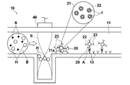
- FIG. 1 shows a schematic configuration of a measuring apparatus according to a first embodiment of the present invention.
- the measuring apparatus according to the present embodiment is configured as an apparatus that detects a biological substance using the above-described micro-channel sensor chip (hereinafter simply referred to as a sensor chip) 10.
- a sensor chip the micro-channel sensor chip
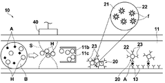
- the sensor chip 10 is detachably attached to the measuring apparatus main body. As shown in FIGS. 1 and 2, the sensor chip 10 includes a flow channel member 12 having a micro flow channel 11 through which a sample solution flows, and a micro flow channel 11.
- the sensor part 14 which fixes one substance 13 of the two substances that specifically bind to each other to the wall surface, and the upper plate member 17 fixed on the flow path member 12 And.
- the flow path member 12 is formed with a concave portion 11a that is recessed downward from the micro flow path 11 on the upstream side of the sensor section 14, that is, on the left side in the drawing. As will be described later, the concave portion 11a functions as a particle capturing portion.
- the substance 13 will be described as an antibody that specifically binds to the antigen A as a substance to be detected.
- the antibody 13 may be directly fixed to the wall surface of the microchannel 11. However, as will be described later, when fluorescence is enhanced by electric field enhancement by surface plasmon, a metal thin film is formed on the wall surface. The antibody 13 is immobilized on.
- the upper plate member 17 communicates the sample liquid inlet 16 a and the sample liquid outlet 16 b opened on the upper surface, and the sample liquid inlet 16 a and the upstream end of the microchannel 11.
- An opening 15 a and an opening 15 b that communicates the sample solution outlet 16 b with the downstream end of the microchannel 11 are provided.
- the upper plate member 17 and the flow path member 12 are joined by, for example, ultrasonic welding.
- the flow path member 12 and the upper plate member 17 are made of a transparent dielectric material such as polystyrene, and are respectively molded by injection molding.
- the labeled antibody 20 is attached to the inner surface of the microchannel 11 on the upstream side of the region where the antibody 13 is fixed.
- the labeled antibody 20 is composed of an antibody 23 that specifically binds to an epitope different from the antibody 13 described above and a fluorescent label 22 with respect to the substance to be detected.
- fluorescent label 22 fluorescent fine particles comprising a large number of fluorescent dye molecules f and a light-transmitting material 21 enclosing the fluorescent dye molecules f are used.
- the size of the fluorescent fine particles is not particularly limited, but is preferably about several tens of nanometers to several hundreds of nanometers. In this example, one having a diameter of about 100 nm is used.
- Specific examples of the light transmissive material 21 include polystyrene and SiO 2 , but any material that can encapsulate the fluorescent dye molecule f and transmit the fluorescence from the fluorescent dye molecule f to be emitted to the outside. There is no particular limitation.
- the labeled antibody 20 in this example is configured by surface-modifying a fluorescent label 22 with a smaller antibody 23.
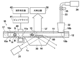
- the total reflection condition is applied to the prism 30 on which the sensor chip 10 is placed, for example, via refractive index matching oil, and the bottom surface of the microchannel 11 (interface between the sensor chip 10 and the sample liquid).
- a light source 31 made of a semiconductor laser or the like that makes the excitation light L 0 incident at an incident angle of: a communication pipe 33 whose one end communicates with the sample liquid outlet 16 b of the sensor chip 10 through a nozzle 32, and this communication pipe 33.
- a sample suction pump 34 having a suction port connected to the other end thereof, an open valve 35 interposed in the communication pipe 33, and fluorescence Lf emitted from the vicinity of the sensor part 14 of the sensor chip 10 as described later. And a photodetector 36 for detection.
- the measuring apparatus includes a piezoelectric element (in this example, a piezo element) 40 serving as an ultrasonic irradiation unit disposed above the flow path member 12 so as to face the concave portion 11a of the micro flow path 11.
- a piezoelectric driver 41 for applying a driving voltage for exciting the piezoelectric element 40 to the piezoelectric element 40; and a waveform generator 42 for generating a waveform signal for defining the waveform of the driving voltage and inputting the waveform signal to the piezoelectric driver 41.
- the ultrasonic irradiation means is not limited to the piezoelectric element, and other piezoelectric ceramics or the like can also be applied.
- Ultrasonic waves are irradiated from the piezoelectric element 40 toward the bottom (ultrasonic irradiation portion) of the recess 11a, and a standing ultrasonic wave S is generated between the ultrasonic irradiation surface of the piezoelectric element 40 and the bottom of the recess 11a. Then, the fine particles in the sample liquid are accumulated in the node portion of the standing ultrasonic wave S.
- the damage of the fine particles can be further reduced by setting the wavelength of the standing ultrasonic wave S to be four times or more the particle size of the fine particles to be captured.
- the wavelength of the standing ultrasonic wave S is preferably at least 80 ⁇ m.
- the distance between the ultrasonic irradiation surface of the piezoelectric element 40 and the bottom of the recess 11a is 750 ⁇ m
- the frequency of the standing ultrasonic wave S to be generated is 1 MHz
- the wavelength is 1500 ⁇ m.
- the piezoelectric element 40 is driven by the piezo driver 41, and the standing ultrasonic wave S is generated between the ultrasonic irradiation surface of the piezoelectric element 40 and the bottom of the recess 11 a so as to cross the minute flow path 11. .
- the whole blood B introduced into the microchannel 11 includes blood cells (red blood cells, white blood cells, and platelets) H as shown schematically in FIG.
- blood cells H red blood cells, white blood cells, and platelets
- FIG. 11 The whole blood B introduced into the microchannel 11 includes blood cells (red blood cells, white blood cells, and platelets) H as shown schematically in FIG.
- blood cells H having a relatively large particle size in the whole blood B are fixed under the influence of the standing ultrasonic wave S. It is accumulated in the node portion of the ultrasound S present. Since the node of the standing ultrasonic wave S is set so as to be located in the recess 11a, the blood cell H is captured in the recess 11a. In this way, the blood cells H are separated from the whole blood B, so that only the plasma flows through the portion of the microchannel 11 downstream of the recess 11a.
- the above plasma is mixed with the labeled antibody 20 adsorbed and fixed to the microchannel 11.
- the antigen A binds to the antibody 23 of the labeled antibody 20
- the antigen A bound to the antibody 23 binds to the antibody 13 of the sensor unit 14, and the antigen A is sandwiched between the antibody 13 and the antibody 23. Is formed.
- the antigen A adsorbed to the sensor unit 14 is detected as follows.
- the excitation light L 0 emitted from the light source 31 is incident on the bottom surface of the microchannel 11 (interface between the sensor chip 10 and the sample liquid) at an incident angle that is a total reflection condition.
- evanescent light oozes out from the inner wall surface of the microchannel 11 to which the antibody 13 is fixed into the sample liquid B.
- the fluorescent label 22 exists in the area where the evanescent light oozes, the fluorescent label 22 is excited to generate fluorescence Lf.
- the fluorescence Lf generated in this way is detected by the photodetector 36.
- the detection of the presence of the fluorescent label 22 as described above means that the presence of the antigen A bound to the antibody 13 is detected. Therefore, based on the fluorescence detection signal from the photodetector 36, the presence or absence of the antigen A and the amount thereof can be detected.
- the blood cell H is captured in the recess 11a, so that basically only the plasma reaches the sensor unit 14. Therefore, the fluorescence Lf is detected well without being affected by scattering or absorption by the blood cell H, and accurate measurement is possible. Moreover, the immune reaction is not inhibited by blood cells. Furthermore, since blood cells H are accumulated not by progressive ultrasound but by standing ultrasound, it is possible to prevent hemolysis during blood cell removal, so that other substances such as specimens are not affected, and immune cells are immune. The assay and chemical analysis can be performed accurately.
- a filter is not arranged in the microchannel 11 in order to capture the blood cells H, so that the filter is clogged and the amount of plasma used for measurement is insufficient.
- it is difficult to obtain an accurate measurement value, and there is a problem that it is necessary to apply a large negative suction pressure to the microchannel 11 by the sample suction pump 34 in order to prevent clogging. I don't have to.
- the antigen A and the labeled antibody 20 that are not bound to the immobilized antibody 13 are suspended, and the labeled antibody 20 is non-specifically adsorbed on the sensor unit 14.
- a cleaning solution may be appropriately introduced into the flow path before the detection of the fluorescence Lf.
- the thickness of the metal film is preferably 50 nm ⁇ 20 nm. More preferably, it is 47 nm ⁇ 10 nm.
- the metal thin film is preferably composed mainly of at least one metal selected from the group consisting of Au, Ag, Cu, Al, Pt, Ni, Ti, and alloys thereof.
- FIG. 4 the same elements as those in FIGS. 1 to 3 are denoted by the same reference numerals, and description thereof will be omitted unless necessary (the same applies hereinafter).
- 4 to 9 described below are all characterized by portions around the piezoelectric element 40, the schematic cross-sectional shapes of only those portions are shown.
- FIG. 4 shows a partial schematic cross-sectional shape around the piezoelectric element 40 of the sensor chip applied to the measuring apparatus according to the second embodiment of the present invention.
- this sensor chip is provided with an ultrasonic reflection member 50 having higher ultrasonic reflectivity than the flow path member 12 on the bottom surface of the recess 11 a of the flow path member 12. Is different.
- the ultrasonic reflecting member 50 for example, aluminum or crown glass can be used. If such an ultrasonic reflecting member 50 is provided, standing ultrasonic waves can be generated more reliably.
- FIG. 5 shows a sensor chip applied to a measuring apparatus according to the third embodiment of the present invention.
- this sensor chip is a region from the ultrasonic irradiated portion (here, the surface of the ultrasonic reflecting member 50) to the node of the standing ultrasonic wave S on the flow channel wall of the micro flow channel.
- an acoustic matching layer 51 for achieving acoustic impedance matching is provided between the sample liquid and the flow path member 12.
- acoustic matching layer 51 for example, polydimethylsiloxane (PDMS) can be used. If such an acoustic matching layer 51 is provided, the blood cells H can be held near the surface of the acoustic matching layer 51, so that the blood cells H can be easily captured and collected.
- PDMS polydimethylsiloxane
- the blood cells H can be adsorbed by hydrophobic interaction. Further, if the position of the surface of the acoustic matching layer 51 is slightly lowered from the position of the node of the standing ultrasonic wave S, the blood cell H cannot be pressed against the surface of the acoustic matching layer 51. It is also possible to prevent hemolysis due to the pressure between the two.
- FIG. 6 shows a sensor chip applied to the measuring apparatus according to the fourth embodiment of the present invention.
- this sensor chip has a distance between the ultrasonic irradiation surface of the piezoelectric element 40 and the bottom of the recess 11a, which is doubled to 1500 ⁇ m, and the node of the standing ultrasonic wave S is a recess. The difference is that two are generated in 11a. Thereby, the collection
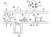
- FIG. 7 shows a sensor chip applied to a measuring apparatus according to the fifth embodiment of the present invention.
- this sensor chip has a particle trapping portion, and a partition wall 11 b that captures blood cells H on the downstream side of the flow path from the position of the node of the standing ultrasonic wave S, instead of the concave portion. It is different.
- the partition wall 11b has a U-shaped cross-section that is open on the upstream side, and is configured to capture blood cells H inside the U-shaped portion.
- an opening 11c is provided in the wall surface on the downstream side of the partition wall 11b so that the cells other than the blood cell H can pass through the partition wall 11b.
- the partition wall 11 b is configured integrally with the flow path member 12. Even in such an embodiment, the blood cells H can be collected.
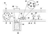
- FIG. 8 shows a sensor chip applied to a measuring apparatus according to the sixth embodiment of the present invention.
- This sensor chip is different from the sensor chip shown in FIG. 3 in that a part of the flow path member 12 is constituted by the piezoelectric element 40. That is, in this case, the piezoelectric element 40 is disposable together with the sensor chip 10.
- the piezoelectric driver 41 see FIG. 1
- the piezoelectric element 40 is disposable together with the sensor chip 10.
- the piezoelectric element 40 is disposable with the sensor chip 10 as described above, the piezoelectric element 40 is preferably composed of, for example, a piezo film with a thickness of several tens of ⁇ m manufactured by Measurement Specialties.
- acoustic impedance matching is achieved between the piezoelectric element 40 and the sample liquid in the microchannel 11 on the surface of the piezoelectric element 40 on the microchannel 11 side.
- an acoustic matching layer 52 made of polydimethylsiloxane (PDMS).
- the measurement apparatus of the present embodiment basically has a metal thin film 60 formed on the flow path wall of the flow path member 12 in the sensor unit 14, and the antibody 13 It differs in that it is formed above.
- the excitation light L 0 emitted from the light source 31 is incident at an incident angle that is a total reflection condition with respect to the bottom surface of the microchannel 11 (the interface between the sensor chip 10 and the metal thin film 60) and is p-polarized light.
- the evanescent light oozes into the sample liquid on the metal thin film 60, and surface plasmons are excited in the metal thin film 60 by the evanescent light.
- This surface plasmon causes an electric field distribution on the surface of the metal film, thereby forming an electric field enhancement region.
- the fluorescent label 22 exists in the area where the evanescent light oozes, the fluorescent label 22 is excited to generate fluorescence Lf.
- the fluorescence Lf is enhanced by the electric field enhancement effect due to the surface plasmons existing in a region substantially equivalent to the region where the evanescent light oozes out.
- the photodetector 36 detects this enhanced fluorescence Lf.
- the presence / absence of the antigen A and the amount thereof can be detected based on the fluorescence detection signal output from the photodetector 36 as in the above-described embodiment.
- the measurement apparatus of the present embodiment is basically different from the measurement apparatus shown in FIG. 1 in that an epi-illumination optical system is employed instead of the total reflection optical system that generates evanescent light.
- the light source 31 is disposed on the upper side of the sensor chip 10 similarly to the photodetector 36, and the excitation light L 0 is emitted from the light source 31 toward the sensor unit 14 of the sensor chip 10. Therefore, in this case, the fluorescent label 22 is directly excited by the excitation light L 0 as propagating light, and the fluorescence Lf is generated.
- the presence / absence of the antigen A and the amount thereof can be detected based on the signal obtained by detecting the fluorescence Lf, as in the above-described embodiment.
- the target substance to be detected by the measurement apparatus of the present invention is not particularly limited as long as it is a substance that can be observed by solidifying genes, cells, etc. in addition to antigens and antibodies.
- a substance that specifically adsorbs them may be fixed to the inner wall of the microchannel.
- the substance to be detected or the substance that specifically binds to the competing substance that competes with the substance to be detected in the sample does not need to be directly fixed to the sensor surface, but is self-assembled monolayer (SAM), SiO It may be fixed via a dielectric film such as 2 or a polymer film such as carboxymethyl dextran.
- SAM self-assembled monolayer
- the combination of a substance to be detected or a competing substance that competes with the substance to be detected in the sample solution and a substance that specifically binds to it is not limited to the antigen and the antibody described above.
- the present invention is also applicable to the case where a combination of substances that bind by a reaction used in a bioassay such as a biotin reaction and an enzyme / substrate reaction is used.
- the labeling substance is not limited to the fluorescent molecule, and other substances having photoresponsive properties such as fluorescent beads and metal fine particles can be applied.
Abstract
【課題】試料液を流通させる微小流路を備えたセンサチップを用いて光学的測定を行う測定装置において、溶血を生じずに全血から簡単に血球を除去してセンサ部に供給可能とする。 【解決手段】流路部材(12)内に試料液を流通させる微小流路(11)が設けられ、この微小流路(11)内の一部にセンサ部(14)が配設されてなるセンサチップ(10)を用いて、試料液中に含まれ得る被検出物質に関する測定を行う測定装置において、流路部材(12)に、センサ部(14)よりも流路上流側において、流路壁が凹んだ状態とされた凹部(11a)を設けるとともに、この凹部(11a)の底と対向する位置に圧電素子(40)を配し、圧電素子(40)の超音波照射面と凹部(11a)の底との間で定在超音波(S)を発生させ、試料液中の血球(H)を定在超音波(S)の節の部分に集積する。
Description
本発明は、試料液中に含まれる可能性が有る被検出物質について測定を行う装置、特に詳細には、試料液を流通させる微小流路を備えたセンサチップを用いて光学的測定を行う測定装置に関するものである。
バイオ測定においては、抗原抗体反応などの生体分子反応を検出することにより、被検出物質である抗原(あるいは抗体)などの存在の有無、量を測定している。
例えば、互いに特異的に結合する2つの物質の一方(抗原、抗体、各種酵素、受容体など)を基板上に固定化し、他方の物質(これは被検出物質そのものであってもよいし、あるいは試料中で被検出物質と競合する競合物質であってもよい)を基板上に固定された固定層に結合させ、この結合反応を検出することにより、試料中における被検出物質の有無、量を測定することができる。具体的には、試料に含まれる被検出物質である抗原を検出するため、基板上にその抗原と特異的に結合する抗体を固定しておき、基板上に試料を供給することにより抗体に抗原を特異的に結合させ、次いで、抗原と特異的に結合する、標識が付与された標識抗体を添加し、抗原と結合させることにより、抗体―抗原―標識抗体の、所謂サンドイッチを形成し、標識からの信号を検出するサンドイッチ法や、標識された競合抗原を被検出物質である抗原と競合的に固定化抗体と結合させ、固定化抗体と結合した競合抗原に付与されている標識からの信号を検出する競合法などのイムノアッセイが知られている。
なお上記サンドイッチ法においては、被検出物質である抗原が上記「他方の物質」に相当し、競合法においては競合抗原が上記「他方の物質」に相当する。後者の競合法においては、固定化抗体と結合した競合抗原の量が多いほど、被検出物質である抗原の量が少ないという関係があるので、この関係に基づいて、競合抗原の量に対応する標識からの信号レベルにより抗原の量を求めることができる。
また、上述のようなバイオ測定に適用可能で、高感度かつ容易な測定法として蛍光検出法が広く用いられている。この蛍光検出法は、特定波長の光により励起されて蛍光を発する被検出物質を含むと考えられる試料に上記特定波長の励起光を照射し、そのとき蛍光を検出することによって被検出物質の存在を確認する方法である。また、被検出物質が蛍光体ではない場合、蛍光色素で標識されて被検出物質と特異的に結合する物質を試料に接触させ、その後上記と同様にして蛍光を検出することにより、この結合すなわち被検出物質の存在を確認することも広くなされている。
以上述べたような光学的手法を用いるバイオ測定においては測定時間の短縮化が望まれており、そこで、センサ部における反応を効率良く生じさせて、測定時間の短縮を図る方法が種々提案されている。例えば特許文献1には、微小流路(マイクロ流路)型のセンサチップを用い、試料液を一定の高速で流下させることにより測定の高速化を図ることが提案されている。この種のセンサチップは、上述した蛍光検出による被検出物質の検出や定量分析を行うために適用することも可能である。
さらに、このような蛍光検出法において、感度を向上させるため、プラズモン共鳴による電場増強の効果を利用する方法が特許文献2等に提案されている。この方法は、透明な支持体上の所定領域に金属層を設けたセンサチップを用い、支持体と金属膜との界面に対して支持体の金属層形成面と反対の面側から、全反射角以上の入射角で励起光を入射させ、この励起光の照射により金属層に表面プラズモンを生じさせ、その電場増強作用によって蛍光を増強させることにより、S/Nを向上させるものである。
ところで、上記のようなバイオ測定に供される試料液の代表的なものとして、人血等の血液が挙げられるが、流路を備えたセンサチップを用いる測定装置は、血液中に含まれ得る被検出物質の検出や定量分析にも適用可能とされている。このように、血液を対象として光学的手法により各種測定を行う場合は、血液中に血球が存在すると、その血球が励起光や被検出光を散乱あるいは吸収するので、測定の感度や精度が損なわれる。また、免疫反応に関わる事象について測定を行う場合は、血球が免疫反応を阻害して、それにより測定の精度が損なわれることもある。そこで多くの場合は、全血から血球を除去した後の血漿を測定にかけるようにしている。したがって、上記のセンサチップを利用する際には、その流路中に設定されたセンサ部よりも流路上流側で、全血から血球を除去しておくことが求められる。
全血から血球を除去する方法としては、センサチップのセンサ部よりも流路上流側に血球分離フィルタを設けることが考えられるが、この場合には血球分離に時間がかかる、目詰まりを防止するためには真空ポンプによって流路に大きな吸引負圧を作用させる必要がある、フィルタが目詰まりして測定に供される血漿量が足りなくなる、といった問題が認められる。特に最後の問題は、いわゆるレート測定法によって測定を行う場合に発生すると、深刻な事態を招くことになる。すなわち、レート測定法とは、単位時間に対する反応量の変化量を測定するものであるが、上記のフィルタに目詰まりが生じてそれが時々刻々進行すると、流路中の血液の流速が次第に低下するために被検出物質が供給不足となって、正確な測定値を求めることが困難になるのである。
このような問題を生じない血球除去の手法として、例えば特許文献3には、流路を流れる全血に対して流れを横切る方向に進行超音波を当て、その放射圧によって血球を押圧することにより、血液を、血球を含むものと含まないもの(血漿)とに分離し、そうして分離された各血液を互いに分岐した別々の流路に導入することが記載されている。この構成によれば、血漿だけをセンサ部に供給することも可能と考えられる。
しかし、特許文献3に示された血球除去の手法を、前述のセンサチップを用いて光学的測定を行う装置に適用した場合、進行超音波により血球が溶血(損傷)するおそれがある。血球の溶血が発生すると、血球内のタンパク質が検体に暴露されるために、その後の免疫アッセイや化学分析に影響を与えるおそれがある。
本発明は上記の事情に鑑みてなされたものであり、試料液を流通させる微小流路を備えたセンサチップを用いて光学的測定を行う測定装置において、溶血を生じずに全血から簡単に血球を除去してセンサ部に供給可能とすることを目的とする。
本発明による測定装置は、流路部材内に試料液を流通させる微小流路が設けられ、この微小流路内の一部にセンサ部が配設されてなるセンサチップを用いて、試料液中に含まれ得る被検出物質に関する測定を行う測定装置において、流路部材のセンサ部よりも流路上流側において微小流路を横断する定在超音波を発生させる超音波照射手段と、定在超音波の節に集積された微小粒子を捕捉する粒子捕捉部とを備えていることを特徴とするものである。
本発明の測定装置においては、粒子捕捉部を、流路部材の流路壁の超音波被照射部(流路壁において超音波が照射される部分)に形成された凹部とするとともに、超音波照射手段を、定在超音波の節を凹部内に位置させるように超音波を照射するものとしてもよい。また、粒子捕捉部を、定在超音波の節の位置よりも流路下流側において微小粒子を捕捉する構造物としてもよい。
ここで、定在超音波が微小粒子に及ぼす力について説明する。この力は下記式のように表せられる。

ただし、
F:捕捉力
ρ0:媒質の密度
c0:媒質での音速
λ:超音波の波長
z:位置座標(音波の伝搬方向の位置座標)
p0:超音波の振幅(音圧)
F:捕捉力
ρ0:媒質の密度
c0:媒質での音速
λ:超音波の波長
z:位置座標(音波の伝搬方向の位置座標)
p0:超音波の振幅(音圧)
z=0(すなわち節の位置)ではsinが0になるので定在超音波が微小粒子に及ぼす力はゼロになる。z=0を基準に正側は定在超音波が微小粒子に及ぼす力の方向が正側になり、負側ではこの力の方向が負側になり、両者ともに微小粒子をz=0(すなわち節の位置)の位置に近づける方向に力が発生する。
また、z=λ/4(すなわち腹の位置)では定在超音波が微小粒子に及ぼす力がピークとなる。z=λ/4より大きい側は定在超音波が微小粒子に及ぼす力の方向が負側になり、小さい側はこの力の方向が正側になり、両者ともに微小粒子をz=λ/4(すなわち腹の位置)の位置から遠ざける方向に力が発生する。
なお、ここで発生する力はsin関数に比例するために、z=0ではゼロの力が、z=0から離れるに従い緩やかに大きくなる力が働く。
つまり、定在超音波の節(z=0)に集積された微小粒子の大きさがλ/4を超えると、微小粒子内に逆方向の力が同時に加えられることになり、物質損傷の可能性が表れる。
従って、微小粒子を損傷させずに定在超音波の節に集積させるためには、超音波照射手段が発生させる超音波の波長は、捕捉対象となる微小粒子の粒径の4倍以上とすることが好ましい。
また、微小流路の流路壁の超音波被照射部に、流路部材よりも超音波の反射率が高い超音波反射部材を設けることが好ましい。
また、微小流路の流路壁の超音波被照射部から定在超音波の節までの領域に、試料液と流路部材との間で音響インピーダンス整合を図る音響整合層を設けることが好ましい。
また、超音波照射手段は、微小流路の流路壁の一部を構成するように配置してもよく、その場合には、超音波照射手段の表面に、超音波照射手段と試料液との間で音響インピーダンス整合を図る音響整合層を設けてもよい。
本発明の測定装置においては、流路部材内に試料液を流通させる微小流路が設けられ、この微小流路内の一部にセンサ部が配設されてなるセンサチップを用いて、試料液中に含まれ得る被検出物質に関する測定を行う測定装置において、超音波照射手段により流路部材のセンサ部よりも流路上流側において微小流路を横断する定在超音波を発生させて、この定在超音波の節の部分に微小粒子を集積し、集積された微小粒子を粒子捕捉部で捕捉するようにしている。上述の通り、定在超音波の節の部分では、定在超音波が微小粒子に及ぼす力がゼロになるので、進行超音波で微小流路を集積する場合と比較して微小粒子の損傷を小さくすることができる。
そのため、特に全血から血球を除去する場合には、溶血を生じずに全血から簡単に血球を除去してセンサ部に供給できるため、検体等の他の物質に影響を及ぼすことがなくなり、免疫アッセイや化学分析を正確行うことが可能となる。
また、粒子捕捉部を、流路部材の流路壁の超音波被照射部に形成された凹部とするとともに、超音波照射手段を、定在超音波の節を凹部内に位置させるように超音波を照射するものとするか、粒子捕捉部を、定在超音波の節の位置よりも流路下流側において微小粒子を捕捉する構造物とすれば、簡単な構成で粒子捕捉部を構成することが可能となる。
また、超音波照射手段が発生させる超音波の波長を、捕捉対象となる微小粒子の粒径の4倍以上とすれば、より微小粒子の損傷を小さくすることができる。
また、微小流路の流路壁の超音波被照射部に、流路部材よりも超音波の反射率が高い超音波反射部材を設ければ、より確実に定在超音波を発生させることができる。
また、微小流路の流路壁の超音波被照射部から定在超音波の節までの領域に、試料液と流路部材との間で音響インピーダンス整合を図る音響整合層を設ければ、音響整合層の表面付近に微小粒子を保持できるようになるので、微小粒子の捕捉や回収を容易にすることができる。
また、超音波照射手段を、微小流路の流路壁の一部を構成するように配置してもよく、その場合に、超音波照射手段の表面に、超音波照射手段と試料液との間で音響インピーダンス整合を図る音響整合層を設ければ、超音波が試料液で反射することが抑えられるので、定在超音波を効率的に発生させることができる。
以下、図面を参照して本発明の実施形態を詳細に説明する。図1は、本発明の第1の実施形態による測定装置の概略構成を示すものである。本実施形態の測定装置は、先に述べた微小流路型センサチップ(以下、単にセンサチップという)10を用いて生体由来物質を検出する装置として構成されたものである。まず図2および図3も参照して、このセンサチップ10について説明する。
センサチップ10は測定装置本体に対して着脱自在とされたものであり、図1および図2に示される通り、試料液が流される微小流路11を有する流路部材12と、微小流路11の一部を構成して、互いに特異的に結合する2つの物質のうちの一方の物質13を壁面に固定しているセンサ部14と、流路部材12の上に固着された上板部材17とを備えている。なおセンサ部14の上流側つまり図中の左側において流路部材12には、微小流路11から下方に凹んだ状態とされた凹部11aが形成されている。この凹部11aは後述するように、粒子捕捉部として機能するものである。
本実施形態では、抗原抗体反応においてサンドイッチ法によるアッセイを行う場合を例とし、そこで上記物質13が、被検出物質である抗原Aと特異的に結合する抗体であるとして説明する。なお、抗体13は直接微小流路11の壁面に固定されてもよいが、後述するように表面プラズモンによる電場増強により蛍光を増強する場合は、この壁面の上に金属薄膜が形成され、その上に抗体13が固定される。
上記上板部材17は、図2に示されるように、上表面に開口した試料液流入口16aおよび試料液流出口16bと、試料液流入口16aと微小流路11の上流端とを連通させる開口15aと、試料液流出口16bと微小流路11の下流端とを連通させる開口15bとを有している。この上板部材17と流路部材12は、例えば超音波溶接により接合されている。
流路部材12および上板部材17はポリスチレン等の透明な誘電体材料からなり、射出成型によりそれぞれ成型されている。
また本例のセンサチップ10においては、図3にも示すように、抗体13が固定されている領域の上流側において微小流路11の内面に、標識抗体20が付着されている。標識抗体20は、被検出物質に対して、前述の抗体13とは異なるエピトープに特異的に結合する抗体23と蛍光標識22とから構成されたものである。ここでは蛍光標識22として、多数の蛍光色素分子fと該蛍光色素分子fを内包する光透過材料21とからなる蛍光微粒子が用いられている。
上記蛍光微粒子の大きさには特に制限はないが、直径数十nm~数百nm程度が好ましく、ここでは一例として直径100nm程度のものが用いられている。光透過材料21としては、具体的には、ポリスチレンやSiO2などが挙げられるが、蛍光色素分子fを内包でき、かつ該蛍光色素分子fからの蛍光を透過させて外部に放出できるものであれば特に制限されない。本例における標識抗体20は、蛍光標識22を、それよりも小さい抗体23により表面修飾して構成されている。
次に図1に戻って測定装置について説明する。この測定装置は、上記センサチップ10が例えば屈折率マッチングオイルを介して載置されるプリズム30と、微小流路11の底面(センサチップ10と試料液との界面)に対して、全反射条件となる入射角で励起光L0を入射させる半導体レーザ等からなる光源31と、センサチップ10の試料液流出口16bにノズル32を介して一端が連通される連通管33と、この連通管33の他端に吸込口が接続された試料吸引ポンプ34と、連通管33に介設された開放弁35と、センサチップ10のセンサ部14の近傍部分から後述するようにして発せられる蛍光Lfを検出する光検出器36とを備えている。
さらにこの測定装置は、微小流路11の前記凹部11aに対向するようにして流路部材12の上方に配置された、超音波照射手段としての圧電素子(本例ではピエゾ素子)40と、この圧電素子40を励振させる駆動電圧を該圧電素子40に印加するピエゾドライバ41と、上記駆動電圧の波形を規定する波形信号を生成してピエゾドライバ41に入力する波形発生器42とを有している。なお超音波照射手段としては、ピエゾ素子に限らず、それ以外の圧電セラミック等を適用することも可能である。
この圧電素子40から凹部11aの底(超音波被照射部)に向けて超音波が照射され、圧電素子40の超音波照射面と凹部11aの底との間で定在超音波Sを発生させ、試料液中の微小粒子を定在超音波Sの節の部分に集積する。
この定在超音波Sの波長は、捕捉対象となる微小粒子の粒径の4倍以上とすることにより、より微小粒子の損傷を小さくすることができる。本実施形態においては、後述するように、全血B中の血球Hを集積することを想定している。血球Hの粒径は最大で20μm程度あるため、定在超音波Sの波長は少なくとも80μm以上とすることが好ましい。
本実施形態においては、圧電素子40の超音波照射面と凹部11aの底との間の距離を750μm、発生させる定在超音波Sの周波数を1MHz、波長を1500μmとする。
次に、この測定装置による被検出物質の検出について説明する。ここでは一例として、試料液としての血液(全血)Bに含まれる可能性のある抗原Aを検出する場合について説明する。まず、図1に示す試料液流入口16aに全血Bが注入され、それとともに試料吸引ポンプ34が駆動され、開放弁35は連通管33を開く状態に設定され、全血Bがセンサチップ10の微小流路11内に導入される。またこのとき、ピエゾドライバ41により圧電素子40が駆動され、微小流路11を横切るように、圧電素子40の超音波照射面と凹部11aの底との間で定在超音波Sが発生させられる。
微小流路11に導入された全血Bは、図3に模式的に示すように血球(赤血球、白血球および血小板)Hを含み、また抗原Aを含み得るものである。この全血Bが、微小流路11の上記凹部11aが設けられている部分に到達すると、全血B中において比較的粒径が大きい血球Hが、定在超音波Sの影響を受けて定在超音波Sの節の部分に集積される。定在超音波Sの節は、凹部11a内に位置するように設定されているため、血球Hがこの凹部11a内に捕捉される。こうして全血Bから血球Hが分離されるので、微小流路11の凹部11aよりも下流側の部分では、ほぼ血漿のみが流れるようになる。
上記の血漿は、微小流路11に吸着固定されている標識抗体20と混ぜ合わされる。それにより、抗原Aが標識抗体20の抗体23と結合し、さらに抗体23と結合した抗原Aが、センサ部14の抗体13と結合し、抗原Aが抗体13と抗体23で挟み込まれたいわゆるサンドイッチが形成される。
このようにしてセンサ部14に吸着した抗原Aは、以下の通りにして検出される。光源31から発せられた励起光L0は、微小流路11の底面(センサチップ10と試料液との界面)に対して、全反射条件となる入射角で入射する。こうして励起光L0が全反射すると、抗体13を固定している微小流路11の内壁面から試料液B中にエバネッセント光が滲み出す。このとき、エバネッセント光の滲み出し領域内に蛍光標識22が存在すると、その蛍光標識22が励起されて蛍光Lfが発生する。こうして発生した蛍光Lfは、光検出器36によって検出される。以上のようにして蛍光標識22の存在を検出することは、すなわち、抗体13と結合した抗原Aの存在を検出することになる。そこで光検出器36の蛍光検出信号に基づいて、抗原Aの存在の有無や、その量を検出可能となる。
本実施形態においては、前述した通り血球Hが凹部11aに捕捉されるので、基本的にセンサ部14には血漿だけが到達する。そこで蛍光Lfは、血球Hによる散乱や吸収の影響を受けることなく良好に検出されるようになり、精度良い測定が可能となる。また、血球によって免疫反応が阻害されるようなこともない。さらに、進行超音波ではなく定在超音波により血球Hを集積しているため、血球除去の際に溶血を生じないようにできるため、検体等の他の物質に影響を及ぼすことがなくなり、免疫アッセイや化学分析を正確行うことが可能となる。
さらに本実施形態の測定装置では、血球Hを捕捉するために微小流路11にフィルタを配置するようなことはしていないので、フィルタが目詰まりして測定に供される血漿量が足りなくなる、そのために正確な測定値を求めることが困難になる、さらには、目詰まりを防止するために試料吸引ポンプ34によって微小流路11に大きな吸引負圧を作用させる必要がある、といった問題が発生することもない。
なお微小流路11中には、固定されている抗体13と結合していない抗原Aや標識抗体20が浮遊しており、またセンサ部14には標識抗体20が非特異吸着している。これらを除去するため、蛍光Lfの検出前に、適宜洗浄液を流路に導入するようにしてもよい。
また、例えば励起光L0として780nmに中心波長を有するレーザ光を用い、前述の金属膜として金(Au)膜を用いる場合、金属膜の厚みは50nm±20nmが好適である。さらに好ましくは、47nm±10nmである。なお、金属薄膜は、Au、Ag、Cu、Al、Pt、Ni、Ti、およびこれらの合金からなる群より選択される少なくとも1種の金属を主成分とするものが好ましい。
次に図4を参照して、本発明の第2の実施形態について説明する。なおこの図4において、図1~3中の要素と同等の要素には同番号を付し、それらについての説明は特に必要のない限り省略する(以下、同様)。また、以下で説明する図4~9の構成は、すべて圧電素子40周辺の部分に特徴が有るものなので、それらの部分のみの概略断面形状を図示してある。
図4は、本発明の第2の実施形態による測定装置に適用されたセンサチップの圧電素子40周辺の部分概略断面形状を示すものである。
このセンサチップは図3に示されたセンサチップと比べると、流路部材12の凹部11aの底面に流路部材12よりも超音波の反射率が高い超音波反射部材50を設けている点が異なるものである。この超音波反射部材50は、例えばアルミニウムやクラウンガラス等を用いることができる。このような超音波反射部材50を設ければ、より確実に定在超音波を発生させることができる。
次に図5は、本発明の第3の実施形態による測定装置に適用されたセンサチップを示すものである。このセンサチップは図4に示されたセンサチップと比べると、微小流路の流路壁の超音波被照射部(ここでは超音波反射部材50表面)から定在超音波Sの節までの領域に、試料液と流路部材12との間で音響インピーダンス整合を図る音響整合層51を設けている点が異なるものである。この音響整合層51は、例えばポリジメチルシロキサン(PDMS:Polydimethylsiloxane)等を用いることができる。このような音響整合層51を設ければ、音響整合層51の表面付近に血球Hを保持できるようになるので、血球Hの捕捉や回収を容易にすることができる。
ここで、音響整合層51の表面を疎水的にしておけば、血球Hを疎水性相互作用で吸着させることも可能になる。また、音響整合層51の表面の位置を定在超音波Sの節の位置よりもわずかに下げておけば、血球Hは音響整合層51表面に押しつけられないので、進行超音波のように壁面との間の圧力で溶血させてしまうことを防ぐことも可能である。
次に図6は、本発明の第4の実施形態による測定装置に適用されたセンサチップを示すものである。このセンサチップは図3に示されたセンサチップと比べると、圧電素子40の超音波照射面と凹部11aの底との間の距離を2倍の1500μmとし、定在超音波Sの節を凹部11a内に2つ発生させるようにした点が異なるものである。これにより血球Hの回収効率を向上させることができる。
次に図7は、本発明の第5の実施形態による測定装置に適用されたセンサチップを示すものである。このセンサチップは図3に示されたセンサチップと比べると、粒子捕捉部を、凹部の代わりに、定在超音波Sの節の位置よりも流路下流側において血球Hを捕捉する隔壁11bとした点が異なるものである。
隔壁11bは、上流側が開口したコ字断面形状であり、コ字部の内側に血球Hを捕捉するように構成されている。また隔壁11bの下流側の壁面には開口11cが設けられており、血球H以外は隔壁11bを通過できるようにしている。この隔壁11bは、流路部材12と一体的に構成されている。このような態様としても血球Hを回収することができる。
次に図8は、本発明の第6の実施形態による測定装置に適用されたセンサチップを示すものである。このセンサチップは図3に示されたセンサチップと比べると、流路部材12の一部が圧電素子40によって構成されている点が異なるものである。すなわちこの場合、圧電素子40はセンサチップ10と共に使い捨てされることになる。そしてセンサチップ10が測定装置本体にセットされると、ピエゾドライバ41(図1参照)と圧電素子40との間で、公知の機構を用いて電気的接続が取られるようになっている。
上述のように圧電素子40をセンサチップ10と共に使い捨てとする場合、圧電素子40は、例えばMeasurement Specialties社製の厚さ数十μmのピエゾフィルム等から構成することが好ましい。
このような態様とした場合、図9に示すように、圧電素子40の微小流路11側の表面に、圧電素子40と微小流路11内の試料液との間で音響インピーダンス整合を図る、ポリジメチルシロキサン(PDMS:Polydimethylsiloxane)等からなる音響整合層52を設けることが好ましい。このような音響整合層52を設けることにより、圧電素子40から発せられた超音波が試料液で反射することが抑制され、良好に凹部11aまで到達できるようになるため、定在超音波Sを効率的に発生させることができる。
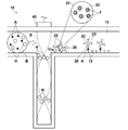
次に図10を参照して、本発明の第7の実施形態による測定装置について説明する。本実施形態の測定装置は、図1に示した測定装置と比べると基本的に、センサ部14において流路部材12の流路壁に金属薄膜60が形成され、抗体13はその金属薄膜60の上に形成されている点が異なるものである。
上記の構成において、光源31から発せられた励起光L0を、微小流路11の底面(センサチップ10と金属薄膜60との界面)に対して全反射条件となる入射角で、かつp偏光として入射させると、金属薄膜60上の試料液中にエバネッセント光が滲み出し、このエバネッセント光によって金属薄膜60中に表面プラズモンが励起される。この表面プラズモンにより金属膜表面に電界分布が生じ、電場増強領域が形成される。
このとき、エバネッセント光の滲み出し領域内に蛍光標識22が存在すると、その蛍光標識22が励起されて蛍光Lfが発生する。ここで、エバネッセント光の染み出し領域とほぼ同等の領域に存在する表面プラズモンによる電場増強効果により、蛍光Lfは増強されたものとなる。光検出器36は、この増強された蛍光Lfを検出する。この光検出器36が出力する蛍光検出信号に基づいて、抗原Aの存在の有無や、その量を検出可能であることは、既述の実施形態におけるのと同様である。
次に図11を参照して、本発明の第8の実施形態による測定装置について説明する。本実施形態の測定装置は、図1に示した測定装置と比べると基本的に、エバネッセント光を発生させる全反射光学系に代えて落射光学系が採用されている点が異なるものである。
すなわち本実施形態においては、光源31が光検出器36と同様にセンサチップ10の上方側に配置され、そこからセンサチップ10のセンサ部14に向けて励起光L0が照射される。したがってこの場合は、伝搬光である励起光L0によって直接的に前記蛍光標識22が励起されて蛍光Lfが発生する。この蛍光Lfを検出した信号に基づいて、抗原Aの存在の有無や、その量を検出可能であることは、既述の実施形態におけるのと同様である。
なお、以上説明した図10や図11の構成を採用する場合においても、図4~9に示したセンサチップの構成を適宜採用可能であることは勿論である。
ここで、本発明の測定装置が対象とする被検出物質は、抗原や抗体の他、遺伝子、細胞などの固層化して観察できる物質であれば、特に制限がない。遺伝子、細胞を検出する場合は、それらに特異的に吸着する物質を微小流路の内壁に固定しておけばよい。反対に、遺伝子、細胞に特異的に吸着する物質を本発明の測定装置によって検出することも可能であり、その場合は遺伝子、細胞を微小流路の内壁に固定しておけばよい。
また、被検出物質、あるいは試料中で被検出物質と競合する競合物質と特異的に結合する物質は、センサ表面に直接固定されている必要はなく、自己組織化単分子膜(SAM)、SiO2等の誘電体膜、カルボキシメチルデキストラン等の高分子膜などを介して固定されていてもよい。
また、被検出物質、あるいはこの被検出物質と試料液中で競合する競合物質と、それと特異的に結合する物質との組合せも、上述した抗原と抗体に限られるものではなく、その他、アビジン・ビオチン反応、酵素・基質反応など、バイオアッセイに使われる反応により結合する物質の組合せが用いられる場合にも、本発明は同様に適用可能である。
さらに、免疫アッセイを適用する場合は、先に説明したサンドイッチアッセイだけではなく、競合法を適用することも可能である。
また標識物質は蛍光分子に限らず、蛍光ビーズ、金属微粒子など光応答性があるその他の物質からなるものも適用可能である。
Claims (8)
- 流路部材内に試料液を流通させる微小流路が設けられ、該微小流路内の一部にセンサ部が配設されてなるセンサチップを用いて、試料液中に含まれ得る被検出物質に関する測定を行う測定装置において、
前記流路部材のセンサ部よりも流路上流側において前記微小流路を横断する定在超音波を発生させる超音波照射手段と、
前記定在超音波の節に集積された微小粒子を捕捉する粒子捕捉部とを備えていることを特徴とする測定装置。 - 前記粒子捕捉部が、前記流路部材の流路壁の超音波被照射部に形成された凹部であり、
前記超音波照射手段が、前記定在超音波の節を前記凹部内に位置させるように超音波を照射するものであることを特徴とする請求項1記載の測定装置。 - 前記粒子捕捉部が、前記定在超音波の節の位置よりも流路下流側において前記微小粒子を捕捉する構造物であることを特徴とする請求項1記載の測定装置。
- 前記超音波照射手段が発生させる超音波の波長が、捕捉対象となる前記微小粒子の粒径の4倍以上であることを特徴とする請求項1から3のいずれか1項記載の測定装置。
- 前記微小流路の流路壁の超音波被照射部に、前記流路部材よりも超音波の反射率が高い超音波反射部材が設けられていることを特徴とする請求項1から4のいずれか1項記載の測定装置。
- 前記微小流路の流路壁の超音波被照射部から前記定在超音波の節までの領域に、試料液と前記流路部材との間で音響インピーダンス整合を図る音響整合層が設けられていることを特徴とする請求項1から5のいずれか1項記載の測定装置。
- 前記超音波照射手段が、前記微小流路の流路壁の一部を構成するように配置されていることを特徴とする請求項1から6のいずれか1項記載の測定装置。
- 前記超音波照射手段の表面に、該超音波照射手段と試料液との間で音響インピーダンス整合を図る音響整合層が設けられていることを特徴とする請求項7記載の測定装置。
Applications Claiming Priority (2)
| Application Number | Priority Date | Filing Date | Title |
|---|---|---|---|
| JP2011-067021 | 2011-03-25 | ||
| JP2011067021A JP2012202789A (ja) | 2011-03-25 | 2011-03-25 | 測定装置 |
Publications (1)
| Publication Number | Publication Date |
|---|---|
| WO2012132313A1 true WO2012132313A1 (ja) | 2012-10-04 |
Family
ID=46930101
Family Applications (1)
| Application Number | Title | Priority Date | Filing Date |
|---|---|---|---|
| PCT/JP2012/001912 WO2012132313A1 (ja) | 2011-03-25 | 2012-03-21 | 免疫測定装置 |
Country Status (2)
| Country | Link |
|---|---|
| JP (1) | JP2012202789A (ja) |
| WO (1) | WO2012132313A1 (ja) |
Cited By (1)
| Publication number | Priority date | Publication date | Assignee | Title |
|---|---|---|---|---|
| CN115308301A (zh) * | 2022-08-16 | 2022-11-08 | 中山大学 | 一种可测量细胞及细胞核的弹性模量的测量装置 |
Families Citing this family (2)
| Publication number | Priority date | Publication date | Assignee | Title |
|---|---|---|---|---|
| JP7202820B2 (ja) * | 2018-09-12 | 2023-01-12 | 株式会社フコク | マイクロ流路チップ |
| EP4310507A1 (en) * | 2021-03-15 | 2024-01-24 | Hitachi High-Tech Corporation | Automatic analysis device |
Citations (6)
| Publication number | Priority date | Publication date | Assignee | Title |
|---|---|---|---|---|
| JP2005319407A (ja) * | 2004-05-10 | 2005-11-17 | Hitachi Ltd | 圧電デバイスを用いた機器 |
| US20060037915A1 (en) * | 2002-06-04 | 2006-02-23 | Protasis Corporation | Method and device for ultrasonically manipulating particles within a fluid |
| JP2008134063A (ja) * | 2006-11-27 | 2008-06-12 | Matsushita Electric Ind Co Ltd | 成分分離デバイスと、この成分分離デバイスを用いた化学分析デバイス |
| WO2010036667A2 (en) * | 2008-09-26 | 2010-04-01 | Abbott Laboratories | Apparatus and method for separation of particles suspended in a liquid from the liquid in which they are suspended |
| JP2010088977A (ja) * | 2008-10-03 | 2010-04-22 | Olympus Corp | 音波発生素子、容器及び攪拌装置 |
| JP2010190880A (ja) * | 2008-04-18 | 2010-09-02 | Fujifilm Corp | 光信号検出方法、光信号検出装置、光信号検出用試料セルおよび光信号検出用キット |
-
2011
- 2011-03-25 JP JP2011067021A patent/JP2012202789A/ja not_active Withdrawn
-
2012
- 2012-03-21 WO PCT/JP2012/001912 patent/WO2012132313A1/ja active Application Filing
Patent Citations (6)
| Publication number | Priority date | Publication date | Assignee | Title |
|---|---|---|---|---|
| US20060037915A1 (en) * | 2002-06-04 | 2006-02-23 | Protasis Corporation | Method and device for ultrasonically manipulating particles within a fluid |
| JP2005319407A (ja) * | 2004-05-10 | 2005-11-17 | Hitachi Ltd | 圧電デバイスを用いた機器 |
| JP2008134063A (ja) * | 2006-11-27 | 2008-06-12 | Matsushita Electric Ind Co Ltd | 成分分離デバイスと、この成分分離デバイスを用いた化学分析デバイス |
| JP2010190880A (ja) * | 2008-04-18 | 2010-09-02 | Fujifilm Corp | 光信号検出方法、光信号検出装置、光信号検出用試料セルおよび光信号検出用キット |
| WO2010036667A2 (en) * | 2008-09-26 | 2010-04-01 | Abbott Laboratories | Apparatus and method for separation of particles suspended in a liquid from the liquid in which they are suspended |
| JP2010088977A (ja) * | 2008-10-03 | 2010-04-22 | Olympus Corp | 音波発生素子、容器及び攪拌装置 |
Cited By (2)
| Publication number | Priority date | Publication date | Assignee | Title |
|---|---|---|---|---|
| CN115308301A (zh) * | 2022-08-16 | 2022-11-08 | 中山大学 | 一种可测量细胞及细胞核的弹性模量的测量装置 |
| CN115308301B (zh) * | 2022-08-16 | 2023-03-10 | 中山大学 | 一种可测量细胞及细胞核的弹性模量的测量装置 |
Also Published As
| Publication number | Publication date |
|---|---|
| JP2012202789A (ja) | 2012-10-22 |
Similar Documents
| Publication | Publication Date | Title |
|---|---|---|
| JP5382852B2 (ja) | 使い捨てチップ型フローセルとそれを用いたフローサイトメーター | |
| JP5295149B2 (ja) | 生体物質分析方法並びにそれに用いられる生体物質分析セル、チップおよび装置 | |
| JP5160776B2 (ja) | チャネルから放出される光子を検知する光子検知方法及びチャネルに光を供給する装置 | |
| JP5308390B2 (ja) | 被検物質検出方法および被検物質検出装置 | |
| US8508742B2 (en) | Integrated shear-vertical surface acoustic wave and surface plasmon resonance sensing device and method | |
| EP2189782A2 (en) | Total reflection illuminated sensor chip | |
| EP2725344A1 (en) | Target substance detection chip, target substance detection plate, target substance detection device and target substance detection method | |
| WO2012132313A1 (ja) | 免疫測定装置 | |
| JP2010210378A (ja) | センシング方法、およびそれに用いられるセンシングキット | |
| JP5288635B2 (ja) | 測定装置 | |
| JP2006275599A (ja) | 微量試料ホルダ、微量試料用センサーセット及び微量試料の検出方法 | |
| JP5315381B2 (ja) | 蛍光検出装置、蛍光検出用の試料セルおよび蛍光検出方法 | |
| JP5797427B2 (ja) | 検出方法および検出装置 | |
| US8716008B2 (en) | Detection method and detection system | |
| JP5192012B2 (ja) | 測定装置 | |
| WO2012096193A1 (ja) | 免疫測定装置 | |
| JP5487127B2 (ja) | 測定装置およびセンサチップ | |
| CN110018136B (zh) | 一种基于光流控的生物分子检测芯片及检测系统 | |
| JP2011221009A (ja) | 生体物質検出装置 | |
| JP5602053B2 (ja) | 被検物質検出方法並びにそれに用いられる被検物質検出チップおよび被検物質検出装置 | |
| JP5556139B2 (ja) | 表面プラズモン共鳴センシングシステム及び、表面プラズモン共鳴インライン測定方法 | |
| JP5297409B2 (ja) | 測定装置 | |
| CN114729889A (zh) | 荧光检测用生物分子检查芯片 | |
| TW201348706A (zh) | 過敏性疾病之可攜式檢測系統 | |
| Wiklund et al. | Ultrasound-enhanced immunoassays and particle sensors |
Legal Events
| Date | Code | Title | Description |
|---|---|---|---|
| 121 | Ep: the epo has been informed by wipo that ep was designated in this application |
Ref document number: 12764107 Country of ref document: EP Kind code of ref document: A1 |
|
| NENP | Non-entry into the national phase |
Ref country code: DE |
|
| 122 | Ep: pct application non-entry in european phase |
Ref document number: 12764107 Country of ref document: EP Kind code of ref document: A1 |