WO2012132013A1 - ノード、リンク形成方法およびリンク形成プログラム - Google Patents
ノード、リンク形成方法およびリンク形成プログラム Download PDFInfo
- Publication number
- WO2012132013A1 WO2012132013A1 PCT/JP2011/058351 JP2011058351W WO2012132013A1 WO 2012132013 A1 WO2012132013 A1 WO 2012132013A1 JP 2011058351 W JP2011058351 W JP 2011058351W WO 2012132013 A1 WO2012132013 A1 WO 2012132013A1
- Authority
- WO
- WIPO (PCT)
- Prior art keywords
- node
- adjacent
- link
- adjacent node
- information
- Prior art date
- Legal status (The legal status is an assumption and is not a legal conclusion. Google has not performed a legal analysis and makes no representation as to the accuracy of the status listed.)
- Ceased
Links
Images






Classifications
-
- H—ELECTRICITY
- H04—ELECTRIC COMMUNICATION TECHNIQUE
- H04W—WIRELESS COMMUNICATION NETWORKS
- H04W84/00—Network topologies
- H04W84/18—Self-organising networks, e.g. ad-hoc networks or sensor networks
-
- H—ELECTRICITY
- H04—ELECTRIC COMMUNICATION TECHNIQUE
- H04W—WIRELESS COMMUNICATION NETWORKS
- H04W40/00—Communication routing or communication path finding
- H04W40/24—Connectivity information management, e.g. connectivity discovery or connectivity update
- H04W40/30—Connectivity information management, e.g. connectivity discovery or connectivity update for proactive routing
Definitions
- the present invention relates to a node, a link formation method, and a link formation program.
- a wireless ad hoc network has been developed that builds a self-distributed network between terminals without using a base station or an access point.
- a wireless ad hoc network is constructed by connecting a large number of terminals (hereinafter referred to as nodes) capable of wireless communication.
- Each node in such a wireless ad hoc network exchanges a Hello message with another adjacent node to detect the presence of the adjacent node. Then, the node registers all the adjacent nodes in the link table in order to form both-path links with all the detected adjacent nodes. Then, after forming a link between nodes, each node performs communication data transfer control using a link table.
- FIG. 13 is a diagram illustrating an example of a conventional link table.
- the link table includes a “link node ID” that uniquely identifies an adjacent node for all adjacent nodes (x nodes in the example of FIG. 13), and the own node direction from the adjacent node.
- “Quality information” which is the communication quality to the mobile phone is stored.
- the conventional technique described above has a problem that the capacity of the link table becomes large. That is, in the conventional technique, since all adjacent nodes are registered in the link table, the number of entries in the link table increases and the capacity of the link table increases.
- the present invention has been made to solve the above-described problems of the prior art and aims to reduce the capacity of the link table.
- the disclosed node includes a receiving unit that receives adjacent node information indicating a node adjacent to the first adjacent node from a first adjacent node adjacent to the own node, and an adjacent node adjacent to the own node, A determination unit that determines whether there is a second adjacent node that is common to the node indicated in the received adjacent node information; and if it is determined that there is a second adjacent node, the second adjacent node or When it is determined that there is no second registration node and a first registration unit that registers information indicating that a one-path link is formed with the first adjacent node in the storage unit, And a second registration unit for registering, in the storage unit, information indicating that a link between both paths is formed with one adjacent node.
- the disclosed node can reduce the capacity of the link table.
- FIG. 1 is a diagram illustrating a communication system configuration according to the first embodiment.
- FIG. 2 is a block diagram illustrating the configuration of the node according to the first embodiment.
- FIG. 3 is a diagram illustrating an example of the routing table.
- FIG. 4 is a diagram illustrating an adjacent node table.
- FIG. 5 is a diagram showing a link table.
- FIG. 6 is a diagram illustrating a configuration example of a Hello frame.
- FIG. 7 is a diagram showing a small loop of a one-path configuration with three nodes.
- FIG. 8 is a diagram showing a bidirectional link between two nodes.
- FIG. 9 is a diagram illustrating processing for forming a link between nodes.
- FIG. 1 is a diagram illustrating a communication system configuration according to the first embodiment.
- FIG. 2 is a block diagram illustrating the configuration of the node according to the first embodiment.
- FIG. 3 is a diagram illustrating an example of the routing table.
- FIG. 4 is
- FIG. 10 is a flowchart for explaining a link forming process procedure of a node when there is a common adjacent node.
- FIG. 11 is a flowchart for explaining a link forming process procedure of a node when there is no common adjacent node.
- FIG. 12 is a diagram illustrating a computer that executes a link formation program.
- FIG. 13 is a diagram illustrating an example of a conventional link table.
- FIG. 1 is a diagram illustrating a communication system configuration according to the first embodiment.
- the communication system 100 includes a plurality of nodes 10A to 10G that form a wireless ad hoc network. Note that the number of nodes forming the wireless ad hoc network is not limited to this.
- Nodes 10A to 10G are communication devices having a short-range wireless communication function such as a computer.
- Each of the nodes 10A to 10G periodically transmits and receives a HELLO message, which is a message including node information such as route information and communication quality information of an inter-node link, between adjacent nodes.
- a HELLO message is a message including node information such as route information and communication quality information of an inter-node link, between adjacent nodes.
- an adjacent node is another node within a range where wireless communication can reach, in other words, another node that can perform wireless communication with 1 Hop.
- the nodes 10B, 10C, and 10F correspond to the adjacent nodes of the node 10A.
- each node 10A to 10G calculates the communication quality of each route obtained by transmitting and receiving the HELLO message, builds a plurality of routes to the final destination based on the result, determines the optimum route, and performs routing. Generate a table.
- each node 10A to 10G recalculates the communication quality of each route from the actual data communication results and the transmission / reception of the HELLO message with the adjacent node, and maintains the route and learns the optimum route. Then, the routing table is changed as needed.
- FIG. 2 is a block diagram illustrating the configuration of the node according to the first embodiment.
- the node 10 includes a communication control I / F 11, a control unit 12, and a storage unit 13. The processing of each of these units will be described below.
- the nodes 10A to 10G shown in FIG. 1 have the same configuration, and are described as the node 10 when the nodes 10A to 10G are described without being distinguished.
- the communication control I / F 11 controls communication related to various information exchanged with adjacent nodes. For example, the communication control I / F 11 transmits and receives HELLO messages to and from adjacent nodes.
- the storage unit 13 stores data and programs necessary for various processes performed by the control unit 12.
- the storage unit 13 includes a routing table 13a, an adjacent node table 13b, and a link table 13c.
- the storage unit 13 is a semiconductor memory device such as a RAM (Random Access Memory), a ROM (Read Only Memory), or a flash memory, or a storage device such as a hard disk or an optical disk.
- the routing table 13a stores information related to the route to the destination node. For example, as illustrated in FIG. 3, the routing table 13a stores a destination GD (Global Destination) that is a global destination address and a transfer destination candidate LD (Local Destination) that is a candidate for a transfer destination address.
- FIG. 3 is a diagram illustrating an example of the routing table.
- the global destination address is a destination address indicating a final destination.
- the transfer destination candidate LD is a transfer destination address candidate to be transferred next when a message is sent to the GD address.
- the routing table 13a includes, as the route quality information, Hop that is the number of hops to the destination, route quality that is the route quality obtained by quantifying the delay on the route to the destination, and the direction from the partner node toward the own node.
- An evaluation value that is communication quality is stored.
- the hop count is the number of transmissions required until the message reaches the GD address.
- the route quality is the communication quality of the route to the destination.
- the evaluation value is the communication quality of the return path.
- the adjacent node table 13b stores information on adjacent nodes. For example, as illustrated in FIG. 4, the adjacent node table 13 b stores an adjacent node ID that uniquely identifies an adjacent node, and quality information that is communication quality from the adjacent node toward the own node.
- the adjacent node table 13b stores an NT (Neighbor Table) that is an adjacent node table held by the adjacent node and an LT (Link Table) that is a link table held by the adjacent node.
- FIG. 4 is a diagram illustrating an adjacent node table.
- the link table 13c stores information related to the node on which the link is formed.
- the link table 13 c includes a link node ID that uniquely identifies the node on which the link is formed, and quality information that is communication quality from the node on which the link is formed toward the own node.
- the link table 13c stores m entries.
- FIG. 5 is a diagram showing a link table.
- link table 13c information for adjacent nodes is not registered by the one-pass registration unit 12c and the both-path registration unit 12d, which will be described later, but information on some adjacent nodes is registered. Detailed registration processing will be described later in detail.
- the control unit 12 has an internal memory for storing a program that defines various processing procedures and necessary data, and executes various processes using these programs.
- the control unit 12 includes a reception unit 12a, a determination unit 12b, a one-pass registration unit 12c, and a both-pass registration unit 12d.
- a CPU Central Processing Unit
- MPU Micro Processing Unit
- the receiving unit 12a receives information on an adjacent node and information on a link indicating an adjacent node in the adjacent node from an adjacent node that is an adjacent node. For example, the receiving unit 12a receives a Hello frame from an adjacent node, and acquires an adjacent node table and a link table included in the Hello frame. Then, the acquired adjacent node table and link table are registered in the adjacent node table 13 b of the storage unit 13.
- FIG. 6 is a diagram illustrating a configuration example of a Hello frame.
- an ad hoc header, a HELLO message header, an adjacent node table (indicated as NT LIST in FIG. 6), and a link table (indicated as LT LIST in FIG. 6) are set in the HELLO frame.
- the ad hoc header includes an LD (Local Destination) that is the destination address of the HELLO frame, an LS (Local Source) that is the address of the transmission source node of the HELLO frame, a packet type that indicates the packet type, and a packet length that indicates the packet size. Is set.
- a Node ID that is an identifier of the transmission source node of the HELLO frame
- an NT LIST number that is the number of entries in the adjacent node table
- an LT LIST number that is the number of entries in the link table are set.
- LD is 6 bytes
- LS 6 bytes
- packet type is 1 byte
- packet length is 2 bytes
- the LT LIST number is 2 bytes.
- the determination unit 12b determines whether there is a common adjacent node common to the node indicated in the received adjacent node information among the adjacent nodes adjacent to the own node 10. For example, the determination unit 12b acquires the adjacent node ID from the adjacent node table of other nodes registered in the adjacent node table 13b (corresponding to the item “NT” in the example of FIG. 4). Then, the determination unit 12b acquires an adjacent node ID adjacent to the own node registered in the adjacent node table 13b.
- the determination unit 12b compares the node ID adjacent to the other node with the adjacent node ID adjacent to the own node, and determines whether a common node ID exists. As a result, when there is a common node ID, the determination unit 12b notifies the one-pass registration unit 12c of an instruction to form a one-pass link. In addition, when the common node ID does not exist, the determination unit 12b notifies the both path registration unit 12d of an instruction to form a link of both paths with an adjacent node.
- the one-path registration unit 12c When the determination unit 12b determines that there is a common adjacent node, the one-path registration unit 12c forms a one-path link with the common adjacent node or the adjacent node that is the transmission source of the adjacent node information. Is registered in the link table 13c. For example, when the one-path registration unit 12c receives an instruction to form a one-path link from the determination unit 12c, the link table of other nodes registered in the adjacent node table 13b (in the example of FIG. 4, “LT”). Equivalent to the item).
- the single path registration unit 12c selects a common adjacent node or an adjacent node that is a transmission source of adjacent node information according to the link direction indicated in the link table of the other node, and sets a single path link to the selected node. Information to be formed is registered in the link table 13c. Thereafter, when the link table of the own node is updated, the one-path registration unit 12c broadcasts the update of the link table 13c to the adjacent nodes using the Hello frame.
- FIG. 7 is a diagram showing a small loop of a one-path configuration with three nodes. In the example of FIG. 7, it is shown that there is a common adjacent node 10C between the node 10A and the node 10B.
- the node 10A forms a one-pass link with the node 10B, and registers the information of the node 10B in the link table 13c. Then, the node 10A broadcasts the LT update to the adjacent nodes 10B and 10C using the Hello frame. Thereafter, the nodes 10B and 10C similarly perform a process of forming a one-path link, whereby a one-path link is formed between the node 10B and the node 10C as shown in FIG. A one-pass link is formed with the node 10A. As a result, a small-loop link having a single-path configuration with three nodes 10A to 10C is formed. In the example of FIG. 7, the arrow indicates the direction of the link.
- the node 10A does not register the information of the node 10C in the link table 13c and does not form the link “node 10A ⁇ node 10C”, but “node 10A ⁇ node 10B”. Form a link. Therefore, the node 10A can transmit data to the node 10C using the node 10B as a transfer destination.
- the both-path registration unit 12d registers, in the link table 13c, information indicating that a link of both paths is formed with the adjacent node that is the transmission source of the adjacent node information. To do. For example, when the path registration unit 12d receives an instruction to form a link between both paths from the determination unit 12b, the path registration unit 12d registers an adjacent node in the link table 13c. Thereafter, the both path registration unit 12d broadcasts the update of the link table 13c to the adjacent nodes in the Hello frame.
- the both-path registration unit 12d broadcasts the update of the link table 13c to the adjacent node in the Hello frame, so that the adjacent node that has received the Hello frame also performs the same link formation process, and the link of both paths Form.
- FIG. 8 is a diagram showing a bidirectional link between two nodes.
- FIG. 8 there is no common adjacent node 10C between the node 10A and the node 10F.
- a bidirectional link is formed between the node 10A and the node 10F.
- the number of entries in the link table 13c cannot be reduced, but it is possible to prevent nodes from being isolated.
- FIG. 9 is a diagram illustrating processing for forming a link between nodes.
- the process which forms the link between the nodes demonstrated below is a process performed only for the fixed time from the time of starting of each node in the communication system 100.
- the node 10A receives a Hello frame from the nodes 10B, 10C, and 10F that are adjacent nodes (step S1). Then, the node 10A receives “B”, “C”, “F” which are IDs of adjacent nodes adjacent to the own node stored in the adjacent node table 13b, and other nodes 10B, 10C included in the received Hello frame. 10F is compared with the IDs of adjacent nodes.
- the node 10 ⁇ / b> A has “B”, “C”, “F” which are IDs of adjacent nodes adjacent to its own node, and “ID” of an adjacent node adjacent to the node 10 ⁇ / b> B.
- the node 10A determines that the adjacent node ID “C” is a common adjacent node, and performs a link formation process with a common node (described later in detail with reference to FIG. 10) (step S3-1). .
- the node 10A registers the ID “B” of the node 10B as a link node in the link table 13c, and forms a one-path link with the node 10B. Thereafter, the node 10 broadcasts the update of the link table 13c to the adjacent node in the Hello frame (Step S4).
- the node 10A compares “B”, “C”, “F”, which are IDs of adjacent nodes adjacent to the own node, with “A”, which is an ID of an adjacent node adjacent to the node 10F (Step S1). S2-2). Then, the node 10A determines that there is no common adjacent node, and performs a link formation process without a common node (described later in detail using FIG. 11) (step S3-2). As a result of the processing, the node 10A registers the ID “F” of the node 10F as a link node in the link table 13c in order to form a link of both paths with the node 10F. Thereafter, the node 10 broadcasts the update of the link table 13c to the adjacent node in the Hello frame (Step S4).
- the node 10A has IDs “B”, “C”, and “F” of adjacent nodes adjacent to its own node, and “A”, “B”, and “ID” of adjacent nodes adjacent to the node 10C. E "is compared. Then, the node 10A determines that the adjacent node ID “B” is a common adjacent node, and performs link formation processing with the common node (step S3-1).
- the link node ID “B” is registered in the link node of the link table, a one-path link is formed in the direction of node A ⁇ node B.
- the link node ID “C” is not registered in the link node.
- the node 10A exchanges information on adjacent nodes between adjacent nodes, and if there is a common node, forms a single path link with 3 nodes, thereby reducing the number of links compared to when forming both path links, The amount used can be reduced. Further, when the process of forming a link between nodes is completed, each node 10 performs a process of deleting the adjacent node table 13b or saves the adjacent node table 13b to an external device.
- FIG. 10 is a flowchart for explaining a link forming process procedure of a node when there is a common adjacent node.
- FIG. 11 is a flowchart for explaining a link forming process procedure of a node when there is no common adjacent node.
- FIG. 10 an example in which a link is formed with the node 10A, the node 10B, and the node 10C will be described.
- FIG. 11 an example in which a link is formed between the node 10A and the node 10F will be described.
- the node 10 ⁇ / b> A includes “own node 10 ⁇ / b> A ⁇ adjacent node 10 ⁇ / b> B”, “adjacent node 10 ⁇ / b> B ⁇ common node 10 ⁇ / b> C”, “common node 10 ⁇ / b> C ⁇ own node 10 ⁇ / b> A” (hereinafter, “a set of ABC direction links”). It is determined whether any of the links exists (step S101).
- step S101 when the node 10A determines that any link does not exist (No in step S101), the process proceeds to step S103. Further, when the node 10A determines that a link exists (Yes in step S101), “own node 10A ⁇ common node 10C”, “common node 10C ⁇ adjacent node 10B”, “adjacent node 10B ⁇ own node 10A”. It is determined whether any one of the links (hereinafter referred to as “ACB direction link group”) exists (step S102).
- step S102 if the node 10A determines that any link exists (Yes in step S102), the direction of the link is not unidirectional, and some error has occurred, and the process is terminated as it is. If the node 10A determines that no link exists (No at step S102), the process proceeds to step S103.
- the node 10A determines whether or not all of the links in the ABC direction link group and the ACB direction link group exist (step S103). As a result, when it is determined that all the links do not exist (Yes at Step S103), the node 10A registers the adjacent node 10B in the link table 13c of the own node 10A (Step S104). Then, the node 10A notifies each adjacent node of the change of the link table 13c with the Hall frame (step S105), and the process is terminated.
- step S103 when the node 10A determines that all the links exist (No in step S103), the node 10A determines whether any of the links in the ABC direction link exists (step S106). As a result, when it is determined that any link is present in the set of ABC direction links (Yes in Step S106), it is determined whether a link of “own node 10A ⁇ adjacent node 10B” exists (Step S107). ).
- the node 10A registers the adjacent node 10B in the link table 13c of the own node 10A (Step S108). Then, the node 10A notifies the adjacent nodes with the HELLO frame of the change of the link table 13c (step S105), and the process is terminated. In addition, when there is a link of “own node 10A ⁇ adjacent node 10B” (Yes at Step S107), the node 10A ends the process as it is.
- step S106 when it is determined that any link in the set of ABC direction links does not exist (No in step S106), the node 10A is a link of “own node 10A ⁇ common node 10C”. Is present (step S109).
- the node 10A registers the common node 10C in the link table 13c of the own node 10A (Step S110). Then, the node 10A notifies the adjacent nodes with the HELLO frame of the change of the link table 13c (step S105), and the process is terminated. Further, when there is a link of “own node 10A ⁇ common node 10C” (Yes at Step S109), the node 10A ends the process as it is.
- the node 10A determines whether the adjacent node 10F exists in the link table 13c of the own node 10A (step S201). As a result, when it is determined that the adjacent node 10F exists (Yes at Step S201), the node 10A ends the process as it is.
- the node 10A registers the adjacent node 10F in the link table 13c of the own node 10A (Step S202). Then, the node 10A notifies each adjacent node of the change of the link table 13c with the HELLO frame (step S203), and ends the process.
- the node 10 receives the adjacent node information indicating the adjacent node in the adjacent node from the adjacent node that is the adjacent node, and the node indicated in the received adjacent node information among the adjacent nodes. It is determined whether there is a common adjacent node that is in common with. When it is determined that there is a common adjacent node, the node 10 links information indicating that a one-path link is formed with the common adjacent node or the adjacent node that is the transmission source of the adjacent node information. Register in the table 13c.
- the node 10 registers information in the link table 13c to form a link of both paths with the adjacent node that is the transmission source of the adjacent node information. . For this reason, the capacity of the link table 13c can be reduced as compared to the case where links of both paths are formed with all adjacent nodes.
- the node 10 further receives the link information stored in the link table 13c from the adjacent node. Then, the node 10 selects the common adjacent node or the adjacent node that is the transmission source of the adjacent node information according to the link direction indicated in the received link information, and forms a one-path link for the selected node. Is registered in the link table 13c. Therefore, the node 10 can reliably form a one-way link in one direction between the three nodes.
- each component of each illustrated device is functionally conceptual and does not necessarily need to be physically configured as illustrated.
- the specific form of distribution / integration of each device is not limited to that shown in the figure, and all or a part thereof may be functionally or physically distributed or arbitrarily distributed in arbitrary units according to various loads or usage conditions.
- the one-pass registration unit 12c and the both-pass registration unit 12d may be integrated.
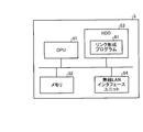
- FIG. 12 is a diagram illustrating a computer that executes a link formation program.
- a CPU 51, a memory 52, an HDD 53, and a wireless LAN interface unit 54 are connected by a bus.
- the HDD 53 stores a link formation program 61 corresponding to the communication terminal device.
- the link formation program 61 is not limited to being stored in the HDD 53, but may be stored in, for example, a removable storage medium and read by the CPU 51 via a disk drive or the like.
- the CPU 51 reads out the link formation program 61, expands it in the memory 52, and sequentially executes the link formation process corresponding to the link formation program 61, thereby causing the computer 5 to execute the same operation as the communication terminal device disclosed.
Landscapes
- Engineering & Computer Science (AREA)
- Computer Networks & Wireless Communication (AREA)
- Signal Processing (AREA)
- Mobile Radio Communication Systems (AREA)
Abstract
ノード(10)は、隣接するノードである隣接ノードから、当該隣接ノードにおいて隣接するノードを示す隣接ノード情報を受信し、隣接ノードのなかに、受信した隣接ノード情報に示されるノードと共通である共通隣接ノードがあるか判定する。そして、ノード(10)は、共通隣接ノードがあると判定された場合には、当該共通隣接ノードまたは隣接ノード情報の送信元である隣接ノードとの間で片パスのリンクを形成する旨の情報をリンクテーブル(13c)に登録する。また、ノード(10)は、共通隣接ノードがないと判定された場合には、隣接ノード情報の送信元である隣接ノードとの間で両パスのリンクを形成する旨の情報をリンクテーブル(13c)に登録する。
Description
本発明は、ノード、リンク形成方法およびリンク形成プログラムに関する。
近年、基地局やアクセスポイントを用いることなく端末間で自立分散型のネットワークを構築する無線アドホックネットワークが開発されている。無線アドホックネットワークは、無線通信が可能な多数の端末(以下、ノードという)が相互に接続されることで構築される。
このような無線アドホックネットワークにおける各ノードは、隣接する他ノードとHelloメッセージを交換して隣接ノードの存在を検出する。そして、ノードは、検出した全ての隣接ノードとの間で両パスのリンクを形成するために、全ての隣接ノードについてリンクテーブルに登録する。そして、ノード間でリンクの形成を行った後、各ノードは、リンクテーブルを用いて、通信データの転送制御を実施する。
ここで、図13を用いて、リンクテーブルの例を説明する。図13は、従来のリンクテーブルの例を示す図である。図13に例示するように、リンクテーブルは、全ての隣接ノード(図13の例では、x個のノード)について、隣接ノードを一意に識別する「リンクノードID」と、隣接ノードから自ノード方向への通信品質である「品質情報」とを記憶する。
しかしながら、上記した従来の技術では、リンクテーブルの容量が大きくなってしまうという課題があった。つまり、従来の技術では、全ての隣接ノードについてリンクテーブルに登録するので、リンクテーブルのエントリ数が多くなり、リンクテーブルの容量が大きくなってしまう。
そこで、この発明は、上述した従来技術の課題を解決するためになされたものであり、リンクテーブルの容量を削減することを目的とする。
開示のノードは、自ノードと隣接する第一の隣接ノードから、当該第一の隣接ノードと隣接するノードを示す隣接ノード情報を受信する受信部と、自ノードと隣接する隣接ノードのなかに、受信した前記隣接ノード情報に示されるノードと共通である第二の隣接ノードがあるか判定する判定部と、第二の隣接ノードがあると判定された場合には、当該第二の隣接ノードまたは前記第一の隣接ノードとの間で片パスのリンクを形成する旨の情報を記憶部に登録する第一の登録部と、第二の隣接ノードがないと判定された場合には、前記第1の隣接ノードとの間で両パスのリンクを形成する旨の情報を前記記憶部に登録する第二の登録部とを有する。
開示のノードは、リンクテーブルの容量を削減することができる。
以下に添付図面を参照して、この発明に係るノード、リンク形成方法およびリンク形成プログラムの実施例を詳細に説明する。なお、この実施例によりこの発明が限定されるものではない。
以下の実施例では、実施例1に係る通信システムの構成、通信システム内のノードの構成およびノードの処理の流れを順に説明し、最後に実施例1による効果を説明する。
[通信システムの構成]
まず、図1を用いて、通信システムの構成を説明する。図1は、実施例1に係る通信システム構成を示す図である。図1に示すように、通信システム100は、無線アドホックネットワークを形成する複数のノード10A~10Gを有する。なお、無線アドホックネットワークを形成するノードの数は、これに限定されるものではない。
まず、図1を用いて、通信システムの構成を説明する。図1は、実施例1に係る通信システム構成を示す図である。図1に示すように、通信システム100は、無線アドホックネットワークを形成する複数のノード10A~10Gを有する。なお、無線アドホックネットワークを形成するノードの数は、これに限定されるものではない。
ノード10A~10Gは、例えばコンピュータなどの近距離無線通信機能を有する通信装置である。このような各ノード10A~10Gは、隣接するノードとの間で経路情報やノード間リンクの通信品質情報などのノード情報を含むメッセージであるHELLOメッセージの送受信を定期的に行う。ここで、隣接するノードとは、無線通信が届く範囲内の他のノードであり、言い換えると、1Hopで無線通信できる他のノードのことをいう。例えば、図1の例を用いて説明すると、ノード10Aの隣接ノードには、ノード10B、ノード10C、ノード10Fが該当する。
そして、各ノード10A~10Gは、HELLOメッセージの送受信で得られた各経路の通信品質を計算し、その結果に基づいて最終宛先までの経路を複数構築し、最適な経路の確定を行ってルーティングテーブルを生成する。また、各ノード10A~10Gは、構築した経路に関して、実際のデータ通信の実績や隣接ノードとのHELLOメッセージの送受信から、各経路の通信品質を再計算し、経路の維持や最適経路の学習をして、ルーティングテーブルの随時変更を行う。
ここで、図2を用いて、図1に示したノードの構成を説明する。図2は、実施例1に係るノードの構成を示すブロック図である図2に示すように、このノード10は、通信制御I/F11、制御部12、記憶部13を有する。以下にこれらの各部の処理を説明する。なお、図1に示したノード10A~10Gは、それぞれ同様の構成であり、ノード10A~10Gを区別せずに説明する場合には、ノード10と記載する。
通信制御I/F11は、隣接ノードとの間でやり取りする各種情報に関する通信を制御する。例えば、通信制御I/F11は、隣接ノードとの間でHELLOメッセージの送受信を行う。
記憶部13は、制御部12による各種処理に必要なデータおよびプログラムを格納する。また、記憶部13は、ルーティングテーブル13a、隣接ノードテーブル13bおよびリンクテーブル13cを有する。なお、記憶部13とは、RAM(Random Access Memory)、ROM(Read Only Memory)、フラッシュメモリ(flash memory)などの半導体メモリ素子、または、ハードディスク、光ディスクなどの記憶装置である。
ルーティングテーブル13aは、宛先ノードまでの経路に関する情報を記憶する。例えば、ルーティングテーブル13aは、図3に例示するように、グローバル宛先アドレスである宛先GD(Global Destination)と、転送先アドレスの候補である転送先候補LD(Local Destination)とを記憶する。図3は、ルーティングテーブルの一例を示す図である。
ここで、グローバル宛先アドレスとは、最終的な宛先を示す宛先アドレスである。また、転送先候補LDとは、GDアドレスにメッセージを送る場合に、次に転送すべき転送先のアドレスの候補である。
また、ルーティングテーブル13aは、経路品質情報として、宛先までのホップ数であるHopと、宛先までの経路上での遅延を数値化した経路品質である経路品質と、相手ノードから自ノード方向への通信品質である評価値とを記憶する。ここで、ホップ数とは、GDアドレスにメッセージが到達するまでに必要な送信の回数である。また、経路品質は、宛先までの経路の通信品質である。また、評価値は、復路の通信品質である。
隣接ノードテーブル13bは、隣接ノードに関する情報を記憶する。例えば、隣接ノードテーブル13bは、図4に例示するように、隣接ノードを一意に識別する隣接ノードIDと、隣接ノードから自ノード方向への通信品質である品質情報とを記憶する。また、隣接ノードテーブル13bは、隣接ノードが保持する隣接ノードテーブルであるNT(Neighbor Table)と、隣接ノードが保持するリンクテーブルであるLT(Link Table)とを記憶する。図4は、隣接ノードテーブルを示す図である。
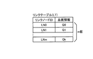
リンクテーブル13cは、リンクが形成されたノードに関する情報を記憶する。例えば、リンクテーブル13cは、図5に例示するように、リンクが形成されたノードを一意に識別するリンクノードIDと、リンクが形成されたノードから自ノード方向への通信品質である品質情報とを記憶する。また、図5の例では、リンクテーブル13cは、m個分のエントリを記憶する。図5は、リンクテーブルを示す図である。
また、リンクテーブル13cは、後述する片パス登録部12cおよび両パス登録部12dによって、全て隣接ノード分の情報が登録されるのではなく、一部の隣接ノードの情報が登録される。なお、詳しい登録処理については、後に詳述する。
制御部12は、各種の処理手順などを規定したプログラムおよび所要データを格納するための内部メモリを有し、これらによって種々の処理を実行する。また、制御部12は、受信部12a、判定部12b、片パス登録部12c、両パス登録部12dを有する。例えば、実施例1のノード10では、制御部12として、CPU(Central Processing Unit)やMPU(Micro Processing Unit)などを適用する。
受信部12aは、隣接するノードである隣接ノードから、隣接ノードにおいて隣接するノードを示す隣接ノードの情報およびリンクの情報を受信する。例えば、受信部12aは、隣接ノードから、Helloフレームを受信し、Helloフレームに含まれる隣接ノードテーブルおよびリンクテーブルを取得する。そして、取得した隣接ノードテーブルおよびリンクテーブルを記憶部13の隣接ノードテーブル13bに登録する。
ここで、図6を用いて、受信部12aが受信するHELLOフレームについて説明する。図6は、Helloフレームの構成例を示す図である。図6に示すように、HELLOフレームは、アドホックヘッダ、HELLOメッセージヘッダ、隣接ノードテーブル(図6では、NT LISTと記載)、リンクテーブル(図6では、LT LISTと記載)が設定される。
アドホックヘッダは、HELLOフレームの宛先アドレスであるLD(Local Destination)と、HELLOフレームの送信元ノードのアドレスであるLS(Local Source)と、パケットの種別を示すパケットタイプ、パケットサイズを示すパケット長とが設定される。また、HELLOメッセージヘッダは、HELLOフレームの送信元ノードの識別子であるNode IDと、隣接ノードテーブルのエントリ数であるNT LIST数と、リンクテーブルのエントリ数であるLT LIST数とが設定される。なお、図6に例示するように、各データサイズについて、例えば、LDが6バイトであり、LSが6バイトであり、パケットタイプが1バイトであり、パケット長が2バイトであり、NT LIST数が2バイトであり、LT LIST数が2バイトである。
判定部12bは、自ノード10と隣接する隣接ノードのなかに、受信した隣接ノード情報に示されるノードと共通である共通隣接ノードがあるか判定する。例えば、判定部12bは、隣接ノードテーブル13bに登録された他ノードの隣接ノードテーブル(図4の例では、「NT」の項目に相当)から隣接ノードIDを取得する。そして、判定部12bは、隣接ノードテーブル13bに登録された自ノードと隣接する隣接ノードIDを取得する。
判定部12bは、他ノードと隣接するノードIDと、自ノードと隣接する隣接ノードIDとを比較し、共通のノードIDが存在するか判定する。この結果、判定部12bは、共通のノードIDが存在する場合には、片パスのリンクを形成する旨の指示を片パス登録部12cに通知する。また、判定部12bは、共通のノードIDが存在しない場合には、隣接ノードとの間で両パスのリンクを形成する旨の指示を両パス登録部12dに通知する。
片パス登録部12cは、判定部12bによって共通隣接ノードがあると判定された場合には、共通隣接ノードまたは隣接ノード情報の送信元である隣接ノードとの間で片パスのリンクを形成する旨の情報をリンクテーブル13cに登録する。例えば、片パス登録部12cは、片パスのリンクを形成する旨の指示を判定部12cから受信すると、隣接ノードテーブル13bに登録された他ノードのリンクテーブル(図4の例では、「LT」の項目に相当)を取得する。
そして、片パス登録部12cは、他ノードのリンクテーブルに示されるリンク方向に従って、共通隣接ノードまたは隣接ノード情報の送信元である隣接ノードを選択し、選択したノードに対して片パスのリンクを形成する旨の情報をリンクテーブル13cに登録する。その後、片パス登録部12cは、自ノードのリンクテーブルに更新があった場合に、Helloフレームにてリンクテーブル13cの更新を隣接ノードにブロードキャストする。
このように、HelloフレームにてLT更新を隣接ノードにブロードキャストすることで、Helloフレームを受信した隣接ノードも同様のリンク形成処理を実施する。これにより、図7に例示するように、小ループのリンクが形成される。ここで、図7の例を用いて、3ノードによる片パス構成の小ループのリンクについて説明する。図7は、3ノードによる片パス構成の小ループを示す図である。図7の例では、ノード10Aとノード10Bとの間に共通する隣接ノード10Cがあることを示している。
まず、図7に示すように、ノード10Aは、ノード10Bとの間で片パスのリンクを形成し、ノード10Bの情報をリンクテーブル13cに登録する。そして、ノード10Aは、HelloフレームにてLT更新を隣接ノード10B、10Cにブロードキャストする。その後、ノード10B、10Cがそれぞれ同様に片パスのリンクを形成する処理を行うことで、図7に示すように、ノード10Bとノード10Cとの間で片パスのリンクが形成され、ノード10Cとノード10Aとの間で片パスのリンクが形成される。これにより、ノード10A~10Cの3ノードによる片パス構成の小ループのリンクが形成される。なお、図7の例では、矢印がリンクの方向を示している。
このように、最小限のループを構成するようにリンク関係を形成することで、ノード間の到達率を確保できる。つまり、3つのノードの小ループの片パス構成が構成されるとき、自ノードがリンクしているノードを転送先として利用可能なので、リンクする必要がなくなる。
このため、通信システム100では、ノード間のデータ到達率を確保しつつ、リンクテーブル13cに登録するエントリ数を減らすことができる。図7の例で説明すると、ノード10Aは、リンクテーブル13cにノード10Cの情報を登録しておらず、「ノード10A→ノード10C」のリンクを形成していないが、「ノード10A→ノード10B」のリンクを形成している。このため、ノード10Aは、ノード10Bを転送先として利用してノード10Cにデータを送信できる。
両パス登録部12dは、共通隣接ノードがないと判定された場合には、隣接ノード情報の送信元である隣接ノードとの間で両パスのリンクを形成する旨の情報をリンクテーブル13cに登録する。例えば、両パス登録部12dは、両パスのリンクを形成する旨の指示を判定部12bから受信すると、リンクテーブル13cに隣接ノードを登録する。その後、両パス登録部12dは、Helloフレームにてリンクテーブル13cの更新を隣接ノードにブロードキャストする。
このように、両パス登録部12dは、Helloフレームにてリンクテーブル13cの更新を隣接ノードにブロードキャストすることで、Helloフレームを受信した隣接ノードも同様のリンク形成処理を実施し、両パスのリンクを形成する。
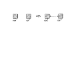
ここで、図8の例を用いて、2ノード間の双方向リンクについて説明する。図8は、2ノード間の双方向リンクを示す図である。図8に示すように、ノード10Aとノード10Fとの間に共通する隣接ノード10Cがない。そして、図8に示すように、ノード10Aとノード10Fとの間で双方向リンクを形成する。このように、双方向リンクを形成することで、リンクテーブル13cのエントリ数を減らすことはできないが、ノードが孤立することを防ぐことができる。
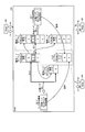
次に、図9を用いて、ノード間でのリンクを形成する処理を説明する。図9は、ノード間でのリンクを形成する処理を説明する図である。なお、以下に説明するノード間でのリンクを形成する処理は、通信システム100における各ノードの起動時から一定時間だけ行われる処理である。図9に示すように、ノード10Aは、隣接ノードであるノード10B、10C、10FからHelloフレームを受信する(ステップS1)。そして、ノード10Aは、隣接ノードテーブル13bに記憶された自ノードと隣接する隣接ノードのIDである「B」、「C」、「F」と、受信したHelloフレームに含まれる他ノード10B、10C、10Fと隣接する隣接ノードのIDとを比較する。
図9の例を用いて説明すると、ノード10Aは、自ノードと隣接する隣接ノードのIDである「B」、「C」、「F」と、ノード10Bと隣接する隣接ノードのIDである「A」、「C」、「D」、「E」とを比較する(ステップS2-1)。そして、ノード10Aは、隣接ノードのID「C」が共通する隣接ノードであると判定し、共通ノードありのリンク形成処理(後に、図10を用いて詳述)を行う(ステップS3-1)。処理の結果、ノード10Aは、リンクテーブル13cにリンクノードとして、ノード10BのID「B」を登録して、ノード10Bとの間で片パスのリンクを形成する。その後、ノード10は、Helloフレームにてリンクテーブル13cの更新を隣接ノードにブロードキャストする(ステップS4)。
また、ノード10Aは、自ノードと隣接する隣接ノードのIDである「B」、「C」、「F」と、ノード10Fと隣接する隣接ノードのIDである「A」とを比較する(ステップS2-2)。そして、ノード10Aは、共通する隣接ノードがないと判定し、共通ノードなしのリンク形成処理(後に、図11を用いて詳述)を行う(ステップS3-2)。処理の結果、ノード10Aは、ノード10Fとの間で両パスのリンクを形成するために、リンクテーブル13cにリンクノードとして、ノード10FのID「F」を登録する。その後、ノード10は、Helloフレームにてリンクテーブル13cの更新を隣接ノードにブロードキャストする(ステップS4)。
また、ノード10Aは、自ノードと隣接する隣接ノードのIDである「B」、「C」、「F」と、ノード10Cと隣接する隣接ノードのIDである「A」、「B」、「E」を比較する。そして、ノード10Aは、隣接ノードのID「B」が共通する隣接ノードであると判定し、共通ノードありのリンク形成処理を行う(ステップS3-1)。ここで、上記で説明したように、リンクテーブルのリンクノードにリンクノードID「B」が登録されたことにより、ノードA→ノードBの方向で片パスリンクが形成されているので、リンクテーブルのリンクノードにリンクノードID「C」を登録しない。
これにより、ノード10Aは、隣接ノードの情報を隣接ノード間で交換し、共通ノードがあれば3ノードで片パスリンクを形成することで、両パスリンク形成時よりもリンク数を減らし、メモリの使用量を削減することができる。また、ノード間でのリンクを形成する処理が終了した場合には、各ノード10は、隣接ノードテーブル13bを削除する処理を行うか、または、隣接ノードテーブル13bを外部の装置に退避させる。
[ノードによる処理]
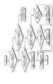
次に、図10、図11を用いて、実施例1に係るノードによる処理を説明する。図10は、共通隣接ノードがある場合におけるノードのリンク形成処理手順を説明するためのフローチャートである。図11は、共通隣接ノードがない場合におけるノードのリンク形成処理手順を説明するためのフローチャートである。図10の例では、ノード10A、ノード10B、ノード10Cとの間でリンクを形成する場合の例を説明する。図11の例では、ノード10Aとノード10Fとの間でリンクを形成する場合の例を説明する。
次に、図10、図11を用いて、実施例1に係るノードによる処理を説明する。図10は、共通隣接ノードがある場合におけるノードのリンク形成処理手順を説明するためのフローチャートである。図11は、共通隣接ノードがない場合におけるノードのリンク形成処理手順を説明するためのフローチャートである。図10の例では、ノード10A、ノード10B、ノード10Cとの間でリンクを形成する場合の例を説明する。図11の例では、ノード10Aとノード10Fとの間でリンクを形成する場合の例を説明する。
図10の例では、自ノードをノード10A、ノード10Aに隣接する隣接ノードをノード10B、ノード10Aとノード10Bと共通する隣接ノードである共通ノードをノード10Cとして説明する。図10に示すように、ノード10Aは、「自ノード10A→隣接ノード10B」、「隣接ノード10B→共通ノード10C」、「共通ノード10C→自ノード10A」(以下、「ABC方向リンクの組」という)のうち、いずれかのリンクが存在するか判定する(ステップS101)。
この結果、ノード10Aは、いずれのリンクが存在しないと判定した場合には(ステップS101否定)、ステップS103に進む。また、ノード10Aは、リンクが存在すると判定した場合には(ステップS101肯定)、「自ノード10A→共通ノード10C」、「共通ノード10C→隣接ノード10B」、「隣接ノード10B→自ノード10A」(以下、「ACB方向リンクの組」という)のうち、いずれかのリンクが存在するか判定する(ステップS102)。
この結果、ノード10Aは、いずれかのリンクが存在すると判定した場合には(ステップS102肯定)、リンクの向きが一方向ではなく、何かしらのエラーが生じており、そのまま処理を終了する。また、ノード10Aは、いずれのリンクも存在しないと判定した場合には(ステップS102否定)、ステップS103に進む。
そして、ノード10Aは、ABC方向リンクの組およびACB方向リンクの組のうち、全てのリンクが存在しないか判定する(ステップS103)。この結果、ノード10Aは、全てのリンクが存在しないと判定した場合には(ステップS103肯定)、自ノード10Aのリンクテーブル13cに隣接ノード10Bを登録する(ステップS104)。そして、ノード10Aは、リンクテーブル13cの変更をHalloフレームで隣接する各ノードに通知し(ステップS105)処理を終了する。
また、S103において、ノード10Aは、全てのリンクが存在すると判定した場合には(ステップS103否定)、ABC方向リンクの組のうち、いずれかのリンクが存在するか判定する(ステップS106)。この結果、ABC方向リンクの組のうち、いずれかのリンクが存在すると判定された場合には(ステップS106肯定)、「自ノード10A→隣接ノード10B」のリンクが存在するか判定する(ステップS107)。
この結果、ノード10Aは、「自ノード10A→隣接ノード10B」のリンクが存在しない場合には(ステップS107否定)、自ノード10Aのリンクテーブル13cに隣接ノード10Bを登録する(ステップS108)。そして、ノード10Aは、リンクテーブル13cの変更をHELLOフレームで隣接する各ノードに通知し(ステップS105)処理を終了する。また、ノード10Aは、「自ノード10A→隣接ノード10B」のリンクが存在する場合には(ステップS107肯定)、そのまま処理を終了する。
S106の処理に戻って、ノード10Aは、ABC方向リンクの組のうち、いずれかのリンクが存在しないと判定された場合には(ステップS106否定)、「自ノード10A→共通ノード10C」のリンクが存在するか判定する(ステップS109)。
この結果、ノード10Aは、「自ノード10A→共通ノード10C」のリンクが存在しない場合には(ステップS109否定)、自ノード10Aのリンクテーブル13cに共通ノード10Cを登録する(ステップS110)。そして、ノード10Aは、リンクテーブル13cの変更をHELLOフレームで隣接する各ノードに通知し(ステップS105)処理を終了する。また、ノード10Aは、「自ノード10A→共通ノード10C」のリンクが存在する場合には(ステップS109肯定)、そのまま処理を終了する。
次に、図11を用いて、共通隣接ノードがない場合におけるノードのリンク形成処理手順を説明する。図11の例では、自ノード10Aをノード10A、ノード10Aに隣接する隣接ノードをノード10Fとして説明する。図11に示すように、ノード10Aは、自ノード10Aのリンクテーブル13cに隣接ノード10Fが存在するか判定する(ステップS201)。この結果、ノード10Aは、隣接ノード10Fが存在すると判定した場合には(ステップS201肯定)、そのまま処理を終了する。
また、ノード10Aは、隣接ノード10Fが存在しないと判定した場合には(ステップS201否定)、自ノード10Aのリンクテーブル13cに隣接ノード10Fを登録する(ステップS202)。そして、ノード10Aは、リンクテーブル13cの変更をHELLOフレームで隣接する各ノードに通知し(ステップS203)、処理を終了する。
[実施例1の効果]
上述してきたように、ノード10は、隣接するノードである隣接ノードから、当該隣接ノードにおいて隣接するノードを示す隣接ノード情報を受信し、隣接ノードのなかに、受信した隣接ノード情報に示されるノードと共通である共通隣接ノードがあるか判定する。そして、ノード10は、共通隣接ノードがあると判定された場合には、当該共通隣接ノードまたは隣接ノード情報の送信元である隣接ノードとの間で片パスのリンクを形成する旨の情報をリンクテーブル13cに登録する。また、ノード10は、共通隣接ノードがないと判定された場合には、隣接ノード情報の送信元である隣接ノードとの間で両パスのリンクを形成する旨の情報をリンクテーブル13cに登録する。このため、全ての隣接ノードとの間で両パスのリンクを形成する場合に比較して、リンクテーブル13cの容量を削減することができる。
上述してきたように、ノード10は、隣接するノードである隣接ノードから、当該隣接ノードにおいて隣接するノードを示す隣接ノード情報を受信し、隣接ノードのなかに、受信した隣接ノード情報に示されるノードと共通である共通隣接ノードがあるか判定する。そして、ノード10は、共通隣接ノードがあると判定された場合には、当該共通隣接ノードまたは隣接ノード情報の送信元である隣接ノードとの間で片パスのリンクを形成する旨の情報をリンクテーブル13cに登録する。また、ノード10は、共通隣接ノードがないと判定された場合には、隣接ノード情報の送信元である隣接ノードとの間で両パスのリンクを形成する旨の情報をリンクテーブル13cに登録する。このため、全ての隣接ノードとの間で両パスのリンクを形成する場合に比較して、リンクテーブル13cの容量を削減することができる。
また、実施例1によれば、ノード10は、隣接ノードからリンクテーブル13cに記憶されたリンクの情報をさらに受信する。そして、ノード10は、受信したリンクの情報に示されるリンク方向に従って、共通隣接ノードまたは隣接ノード情報の送信元である隣接ノードを選択し、選択したノードに対して片パスのリンクを形成する旨の情報をリンクテーブル13cに登録する。このため、ノード10は、3ノード間で確実に一方向の片パスリンクを形成することができる。
さて、これまで本発明の実施例について説明したが、本発明は上述した実施例以外にも、種々の異なる形態にて実施されてよいものである。そこで、以下では実施例2として本発明に含まれる他の実施例を説明する。
(1)システム構成等
図示した各装置の各構成要素は機能概念的なものであり、必ずしも物理的に図示の如く構成されていることを要しない。すなわち、各装置の分散・統合の具体的形態は図示のものに限られず、その全部または一部を、各種の負荷や使用状況などに応じて、任意の単位で機能的または物理的に分散・統合して構成することができる。例えば、片パス登録部12cと両パス登録部12dを統合してもよい。
図示した各装置の各構成要素は機能概念的なものであり、必ずしも物理的に図示の如く構成されていることを要しない。すなわち、各装置の分散・統合の具体的形態は図示のものに限られず、その全部または一部を、各種の負荷や使用状況などに応じて、任意の単位で機能的または物理的に分散・統合して構成することができる。例えば、片パス登録部12cと両パス登録部12dを統合してもよい。
(2)プログラム
ところで、上記の実施例で説明した各種の処理は、あらかじめ用意されたプログラムをコンピュータで実行することによって実現することができる。そこで、以下では、図12を用いて、上記の実施例と同様の機能を有するプログラムを実行するコンピュータの一例を説明する。図12は、リンク形成プログラムを実行するコンピュータを示す図である。
ところで、上記の実施例で説明した各種の処理は、あらかじめ用意されたプログラムをコンピュータで実行することによって実現することができる。そこで、以下では、図12を用いて、上記の実施例と同様の機能を有するプログラムを実行するコンピュータの一例を説明する。図12は、リンク形成プログラムを実行するコンピュータを示す図である。
図12に示したコンピュータ5は、CPU51、メモリ52、HDD53および無線LANインタフェースユニット54がバス接続されている。また、HDD53には、通信端末装置に対応するリンク形成プログラム61が格納されている。なお、リンク形成プログラム61は、HDD53に記憶される場合に限られず、例えば着脱可能な記憶媒体に記憶され、ディスクドライブなどを介してCPU51によって読み出されてもよい。
CPU51は、リンク形成プログラム61を読み出してメモリ52に展開し、リンク形成プログラム61に対応するリンク形成プロセスを順次実行することで、コンピュータ5に開示の通信端末装置と同様の動作を実行させる。
10、10A~10G ノード
11 通信制御I/F
12 制御部
12a 受信部
12b 判定部
12c 片パス登録部
12d 両パス登録部
13 記憶部
13a ルーティングテーブル
13b 隣接ノードテーブル
13c リンクテーブル
100 通信システム
11 通信制御I/F
12 制御部
12a 受信部
12b 判定部
12c 片パス登録部
12d 両パス登録部
13 記憶部
13a ルーティングテーブル
13b 隣接ノードテーブル
13c リンクテーブル
100 通信システム
Claims (6)
- 複数のノードから構成される無線アドホックネットワークにおけるノードであって、
自ノードと隣接する第一の隣接ノードから、当該第一の隣接ノードと隣接するノードを示す隣接ノード情報を受信する受信部と、
自ノードと隣接する隣接ノードのなかに、受信した前記隣接ノード情報に示されるノードと共通である第二の隣接ノードがあるか判定する判定部と、
第二の隣接ノードがあると判定された場合には、当該第二の隣接ノードまたは前記第一の隣接ノードとの間で片パスのリンクを形成する旨の情報を記憶部に登録する第一の登録部と、
第二の隣接ノードがないと判定された場合には、前記第1の隣接ノードとの間で両パスのリンクを形成する旨の情報を前記記憶部に登録する第二の登録部と
を有することを特徴とするノード。 - 前記受信部は、前記第一の隣接ノードから前記第一の隣接ノードが記憶するリンク情報をさらに受信し、
前記第一の登録部は、受信した前記リンク情報に示されるリンク方向に従って、前記第二の隣接ノードまたは前記第一の隣接ノードを選択し、選択したノードに対して片パスのリンクを形成する旨の情報を自ノードの記憶部に登録することを特徴とする請求項1に記載のノード。 - 複数のノードと無線アドホックネットワークを形成するノードが、他のノードとの間でリンクを形成するリンク形成方法であって、
自ノードと隣接する第一の隣接ノードから、当該第一の隣接ノードと隣接するノードを示す隣接ノード情報を受信し、
自ノードと隣接する隣接ノードのなかに、受信した前記隣接ノード情報に示されるノードと共通である第二の隣接ノードがあるか判定し、
第二の隣接ノードがあると判定された場合には、当該第二の隣接ノードまたは前記第一の隣接ノードとの間で片パスのリンクを形成する旨の情報を記憶部に登録し、
第二の隣接ノードがないと判定された場合には、前記第一の隣接ノードとの間で両パスのリンクを形成する旨の情報を前記記憶部に登録することを特徴とするリンク形成方法。 - 前記第一の隣接ノードから前記第一の隣接ノードが記憶するリンク情報をさらに受信し、
受信した前記リンク情報に示されるリンク方向に従って、前記第二の隣接ノードまたは前記第一の隣接ノードを選択し、選択したノードに対して片パスのリンクを形成する旨の情報を自ノードの記憶部に登録することを特徴とする請求項3に記載のリンク形成方法。 - 複数のノードと無線アドホックネットワークを形成するノードとなるコンピュータに、他のノードとの間でリンクを形成するリンク形成方法を実行させるプログラムであって、
自ノードと隣接する第一の隣接ノードから、当該第一の隣接ノードと隣接するノードを示す隣接ノード情報を受信し、
自ノードと隣接する隣接ノードのなかに、受信した前記隣接ノード情報に示されるノードと共通である第二の隣接ノードがあるか判定し、
第二の隣接ノードがあると判定された場合には、当該第二の隣接ノードまたは前記第一の隣接ノードとの間で片パスのリンクを形成する旨の情報を記憶部に登録し、
第二の隣接ノードがないと判定された場合には、前記第一の隣接ノードとの間で両パスのリンクを形成する旨の情報を前記記憶部に登録する
処理を実行させるリンク形成プログラム。 - 前記第一の隣接ノードから前記第一の隣接ノードが記憶するリンク情報をさらに受信し、
受信した前記リンク情報に示されるリンク方向に従って、前記第二の隣接ノードまたは前記第一の隣接ノードを選択し、選択したノードに対して片パスのリンクを形成する旨の情報を自ノードの記憶部に登録する処理を実行させる請求項5に記載のリンク形成方法。
Priority Applications (3)
| Application Number | Priority Date | Filing Date | Title |
|---|---|---|---|
| PCT/JP2011/058351 WO2012132013A1 (ja) | 2011-03-31 | 2011-03-31 | ノード、リンク形成方法およびリンク形成プログラム |
| JP2013507015A JP5664768B2 (ja) | 2011-03-31 | 2011-03-31 | ノード、リンク形成方法およびリンク形成プログラム |
| US14/038,825 US9374849B2 (en) | 2011-03-31 | 2013-09-27 | Node and link formation method |
Applications Claiming Priority (1)
| Application Number | Priority Date | Filing Date | Title |
|---|---|---|---|
| PCT/JP2011/058351 WO2012132013A1 (ja) | 2011-03-31 | 2011-03-31 | ノード、リンク形成方法およびリンク形成プログラム |
Related Child Applications (1)
| Application Number | Title | Priority Date | Filing Date |
|---|---|---|---|
| US14/038,825 Continuation US9374849B2 (en) | 2011-03-31 | 2013-09-27 | Node and link formation method |
Publications (1)
| Publication Number | Publication Date |
|---|---|
| WO2012132013A1 true WO2012132013A1 (ja) | 2012-10-04 |
Family
ID=46929831
Family Applications (1)
| Application Number | Title | Priority Date | Filing Date |
|---|---|---|---|
| PCT/JP2011/058351 Ceased WO2012132013A1 (ja) | 2011-03-31 | 2011-03-31 | ノード、リンク形成方法およびリンク形成プログラム |
Country Status (3)
| Country | Link |
|---|---|
| US (1) | US9374849B2 (ja) |
| JP (1) | JP5664768B2 (ja) |
| WO (1) | WO2012132013A1 (ja) |
Cited By (2)
| Publication number | Priority date | Publication date | Assignee | Title |
|---|---|---|---|---|
| JP2017046255A (ja) * | 2015-08-28 | 2017-03-02 | 沖電気工業株式会社 | 無線通信装置、方法、プログラム及びシステム |
| JP2017050608A (ja) * | 2015-08-31 | 2017-03-09 | 沖電気工業株式会社 | 無線通信装置、方法、プログラム及びシステム |
Families Citing this family (1)
| Publication number | Priority date | Publication date | Assignee | Title |
|---|---|---|---|---|
| WO2013042207A1 (ja) * | 2011-09-20 | 2013-03-28 | 富士通株式会社 | ノード装置および通信方法 |
Citations (2)
| Publication number | Priority date | Publication date | Assignee | Title |
|---|---|---|---|---|
| JP2007266883A (ja) * | 2006-03-28 | 2007-10-11 | Hitachi Kokusai Electric Inc | 無線通信装置 |
| JP2009267532A (ja) * | 2008-04-22 | 2009-11-12 | Fujitsu Ltd | 経路情報中継方法および無線端末 |
Family Cites Families (6)
| Publication number | Priority date | Publication date | Assignee | Title |
|---|---|---|---|---|
| WO2001058237A2 (en) | 2000-02-12 | 2001-08-16 | Hrl Laboratories, Llc | Scalable unidirectional routing for mobile ad-hoc networks |
| US7668958B2 (en) * | 2001-10-18 | 2010-02-23 | Intel Corporation | Method for discovery and routing using a priori knowledge in the form of application programme within mobile AD-HOC networks |
| JP2005168020A (ja) | 2004-11-30 | 2005-06-23 | Nec Corp | 無線マルチホップネットワークの通信経路制御方法及び通信端末 |
| JP4807701B2 (ja) * | 2006-02-28 | 2011-11-02 | 国立大学法人 名古屋工業大学 | 移動端末装置、制御方法及び移動通信システム |
| JP2007266697A (ja) | 2006-03-27 | 2007-10-11 | Toyota Infotechnology Center Co Ltd | 無線通信方法、無線通信装置、および無線通信プログラム |
| US20070268821A1 (en) | 2006-05-17 | 2007-11-22 | Corrigent Systems, Ltd. | Rpr representation in ospf-te |
-
2011
- 2011-03-31 JP JP2013507015A patent/JP5664768B2/ja not_active Expired - Fee Related
- 2011-03-31 WO PCT/JP2011/058351 patent/WO2012132013A1/ja not_active Ceased
-
2013
- 2013-09-27 US US14/038,825 patent/US9374849B2/en not_active Expired - Fee Related
Patent Citations (2)
| Publication number | Priority date | Publication date | Assignee | Title |
|---|---|---|---|---|
| JP2007266883A (ja) * | 2006-03-28 | 2007-10-11 | Hitachi Kokusai Electric Inc | 無線通信装置 |
| JP2009267532A (ja) * | 2008-04-22 | 2009-11-12 | Fujitsu Ltd | 経路情報中継方法および無線端末 |
Cited By (2)
| Publication number | Priority date | Publication date | Assignee | Title |
|---|---|---|---|---|
| JP2017046255A (ja) * | 2015-08-28 | 2017-03-02 | 沖電気工業株式会社 | 無線通信装置、方法、プログラム及びシステム |
| JP2017050608A (ja) * | 2015-08-31 | 2017-03-09 | 沖電気工業株式会社 | 無線通信装置、方法、プログラム及びシステム |
Also Published As
| Publication number | Publication date |
|---|---|
| US20140022950A1 (en) | 2014-01-23 |
| JP5664768B2 (ja) | 2015-02-04 |
| US9374849B2 (en) | 2016-06-21 |
| JPWO2012132013A1 (ja) | 2014-07-24 |
Similar Documents
| Publication | Publication Date | Title |
|---|---|---|
| JP5293744B2 (ja) | ネットワーク通信システム、ノード装置、ルーティング方法、および、ルーティングプログラム | |
| JP4800067B2 (ja) | 通信ノード及びルーティング方法 | |
| US20080112355A1 (en) | Multi-Hop Ad-hoc Wireless Networks That Support Non-Multi-Hop Wireless Terminals | |
| US8213352B2 (en) | Wireless communication system, wireless communication device, wireless communication method, and program | |
| JP2005168020A (ja) | 無線マルチホップネットワークの通信経路制御方法及び通信端末 | |
| JP4720794B2 (ja) | マルチホップ通信ネットワークにおける隣接ノード確認方法、マルチホップ通信ネットワークのノード | |
| JP5036602B2 (ja) | 無線アドホック端末およびアドホック・ネットワーク・システム | |
| US20120155322A1 (en) | Method And Apparatus For Network Node Discovery | |
| JP6264856B2 (ja) | ノード装置、制御プログラム、無線通信システム、及びデータ通信方法 | |
| CN103945413B (zh) | 空洞避免的多跳数据传输方法、装置及系统 | |
| JP5664768B2 (ja) | ノード、リンク形成方法およびリンク形成プログラム | |
| JP5851020B2 (ja) | 通信システム、及び通信方法 | |
| JP4708111B2 (ja) | アドホック・ネットワーク・システムおよびそのノード装置 | |
| JP2015097347A (ja) | ノード装置、制御プログラム、及びノード装置の動作方法 | |
| JP5692404B2 (ja) | 送信制御方法および送信制御装置 | |
| US9450835B2 (en) | Method for turning off routers in a communications network and router implementing this method | |
| JP5860135B2 (ja) | 通信機器探索方法、通信機器、通信機器探索プログラムおよびアドホックネットワークシステム | |
| KR101661879B1 (ko) | 애드-혹 네트워크 내의 패킷 전송 방법 및 장치 | |
| JP2006314147A (ja) | 個人通信無線ネットワークにおけるルーティング経路設定システムおよびその方法 | |
| JP4772019B2 (ja) | 無線通信装置および無線通信システム | |
| JP4913208B2 (ja) | アドレス解決方法 | |
| Marinho et al. | Mobile devices routing using Wi-Fi direct technology | |
| KR20170081904A (ko) | 네트워크의 운용 방법 및 네트워크 장치 | |
| JP4862674B2 (ja) | 無線通信装置および無線通信システム | |
| JP4385926B2 (ja) | 無線通信システム |
Legal Events
| Date | Code | Title | Description |
|---|---|---|---|
| 121 | Ep: the epo has been informed by wipo that ep was designated in this application |
Ref document number: 11862509 Country of ref document: EP Kind code of ref document: A1 |
|
| ENP | Entry into the national phase |
Ref document number: 2013507015 Country of ref document: JP Kind code of ref document: A |
|
| NENP | Non-entry into the national phase |
Ref country code: DE |
|
| 122 | Ep: pct application non-entry in european phase |
Ref document number: 11862509 Country of ref document: EP Kind code of ref document: A1 |