WO2012128448A1 - Procédé et système permettant de fournir un combustible à un moteur à injection de gaz naturel haute pression - Google Patents
Procédé et système permettant de fournir un combustible à un moteur à injection de gaz naturel haute pression Download PDFInfo
- Publication number
- WO2012128448A1 WO2012128448A1 PCT/KR2011/009821 KR2011009821W WO2012128448A1 WO 2012128448 A1 WO2012128448 A1 WO 2012128448A1 KR 2011009821 W KR2011009821 W KR 2011009821W WO 2012128448 A1 WO2012128448 A1 WO 2012128448A1
- Authority
- WO
- WIPO (PCT)
- Prior art keywords
- gas
- refrigerant
- boil
- high pressure
- storage tank
- Prior art date
Links
Images


Classifications
-
- F—MECHANICAL ENGINEERING; LIGHTING; HEATING; WEAPONS; BLASTING
- F17—STORING OR DISTRIBUTING GASES OR LIQUIDS
- F17C—VESSELS FOR CONTAINING OR STORING COMPRESSED, LIQUEFIED OR SOLIDIFIED GASES; FIXED-CAPACITY GAS-HOLDERS; FILLING VESSELS WITH, OR DISCHARGING FROM VESSELS, COMPRESSED, LIQUEFIED, OR SOLIDIFIED GASES
- F17C7/00—Methods or apparatus for discharging liquefied, solidified, or compressed gases from pressure vessels, not covered by another subclass
- F17C7/02—Discharging liquefied gases
- F17C7/04—Discharging liquefied gases with change of state, e.g. vaporisation
-
- F—MECHANICAL ENGINEERING; LIGHTING; HEATING; WEAPONS; BLASTING
- F02—COMBUSTION ENGINES; HOT-GAS OR COMBUSTION-PRODUCT ENGINE PLANTS
- F02M—SUPPLYING COMBUSTION ENGINES IN GENERAL WITH COMBUSTIBLE MIXTURES OR CONSTITUENTS THEREOF
- F02M21/00—Apparatus for supplying engines with non-liquid fuels, e.g. gaseous fuels stored in liquid form
- F02M21/02—Apparatus for supplying engines with non-liquid fuels, e.g. gaseous fuels stored in liquid form for gaseous fuels
- F02M21/0203—Apparatus for supplying engines with non-liquid fuels, e.g. gaseous fuels stored in liquid form for gaseous fuels characterised by the type of gaseous fuel
- F02M21/0215—Mixtures of gaseous fuels; Natural gas; Biogas; Mine gas; Landfill gas
-
- F—MECHANICAL ENGINEERING; LIGHTING; HEATING; WEAPONS; BLASTING
- F02—COMBUSTION ENGINES; HOT-GAS OR COMBUSTION-PRODUCT ENGINE PLANTS
- F02D—CONTROLLING COMBUSTION ENGINES
- F02D19/00—Controlling engines characterised by their use of non-liquid fuels, pluralities of fuels, or non-fuel substances added to the combustible mixtures
- F02D19/06—Controlling engines characterised by their use of non-liquid fuels, pluralities of fuels, or non-fuel substances added to the combustible mixtures peculiar to engines working with pluralities of fuels, e.g. alternatively with light and heavy fuel oil, other than engines indifferent to the fuel consumed
- F02D19/0602—Control of components of the fuel supply system
- F02D19/0605—Control of components of the fuel supply system to adjust the fuel pressure or temperature
-
- F—MECHANICAL ENGINEERING; LIGHTING; HEATING; WEAPONS; BLASTING
- F02—COMBUSTION ENGINES; HOT-GAS OR COMBUSTION-PRODUCT ENGINE PLANTS
- F02M—SUPPLYING COMBUSTION ENGINES IN GENERAL WITH COMBUSTIBLE MIXTURES OR CONSTITUENTS THEREOF
- F02M21/00—Apparatus for supplying engines with non-liquid fuels, e.g. gaseous fuels stored in liquid form
- F02M21/02—Apparatus for supplying engines with non-liquid fuels, e.g. gaseous fuels stored in liquid form for gaseous fuels
- F02M21/0218—Details on the gaseous fuel supply system, e.g. tanks, valves, pipes, pumps, rails, injectors or mixers
- F02M21/0245—High pressure fuel supply systems; Rails; Pumps; Arrangement of valves
-
- F—MECHANICAL ENGINEERING; LIGHTING; HEATING; WEAPONS; BLASTING
- F02—COMBUSTION ENGINES; HOT-GAS OR COMBUSTION-PRODUCT ENGINE PLANTS
- F02M—SUPPLYING COMBUSTION ENGINES IN GENERAL WITH COMBUSTIBLE MIXTURES OR CONSTITUENTS THEREOF
- F02M21/00—Apparatus for supplying engines with non-liquid fuels, e.g. gaseous fuels stored in liquid form
- F02M21/02—Apparatus for supplying engines with non-liquid fuels, e.g. gaseous fuels stored in liquid form for gaseous fuels
- F02M21/0218—Details on the gaseous fuel supply system, e.g. tanks, valves, pipes, pumps, rails, injectors or mixers
- F02M21/0287—Details on the gaseous fuel supply system, e.g. tanks, valves, pipes, pumps, rails, injectors or mixers characterised by the transition from liquid to gaseous phase ; Injection in liquid phase; Cooling and low temperature storage
-
- Y—GENERAL TAGGING OF NEW TECHNOLOGICAL DEVELOPMENTS; GENERAL TAGGING OF CROSS-SECTIONAL TECHNOLOGIES SPANNING OVER SEVERAL SECTIONS OF THE IPC; TECHNICAL SUBJECTS COVERED BY FORMER USPC CROSS-REFERENCE ART COLLECTIONS [XRACs] AND DIGESTS
- Y02—TECHNOLOGIES OR APPLICATIONS FOR MITIGATION OR ADAPTATION AGAINST CLIMATE CHANGE
- Y02T—CLIMATE CHANGE MITIGATION TECHNOLOGIES RELATED TO TRANSPORTATION
- Y02T10/00—Road transport of goods or passengers
- Y02T10/10—Internal combustion engine [ICE] based vehicles
- Y02T10/30—Use of alternative fuels, e.g. biofuels
Definitions
- the present invention relates to a fuel supply system and method for a high pressure natural gas injection engine, and more particularly, to an evaporated gas generated from a liquefied natural gas storage tank in a marine structure using a high pressure natural gas injection engine, such as a ME-GI engine.
- the present invention relates to a fuel supply system and a method for compressing and re-liquefying to medium pressure, and then for high pressure natural gas injection engine by compressing and vaporizing to high pressure.
- Liquefied gas such as LNG (Liquefied Natural Gas) and LPG (Liquefied Petroleum Gas)
- LNG Liquefied Natural Gas
- LPG Liquefied Petroleum Gas
- the liquefied gas is transported in a gas state through a gas pipe on land or sea, or transported to a distant consumer while stored in a liquefied gas carrier in a liquefied state.
- Liquefied gas such as LNG or LPG is obtained by cooling natural gas or petroleum gas to cryogenic temperature (approximately -163 °C in case of LNG), and its volume is greatly reduced than in gas state, so it is very suitable for long distance transportation by sea. .
- Liquefied gas carriers are used to load liquefied gas into the sea and unload this liquefied gas to land requirements.
- a liquefied gas carrier includes a storage tank (commonly referred to as a cargo hold) that can withstand the cryogenic temperature of liquefied gas. do.
- Examples of offshore structures equipped with storage tanks for storing cryogenic liquefied gas are vessels such as LNG RV (Regasification Vessel), LNG Floating Storage and Regasification Unit (FSRU), LNG FPSO (Floating, Production, Structures such as storage and off-loading).
- LNG RV Registered Vessel
- FSRU LNG Floating Storage and Regasification Unit
- LNG FPSO Floating, Production, Structures such as storage and off-loading
- LNG RV is the installation of LNG regasification facilities on liquefied gas carriers that can be self-driving and floating.
- LNG FSRU stores liquefied natural gas, which is unloaded from LNG carriers, in the storage tank after liquefaction as needed.
- It is an offshore structure that vaporizes natural gas and supplies it to land demand.
- LNG FPSO is a marine structure that is used to directly purify mined natural gas from the sea and liquefy directly to store it in a storage tank, and to transfer LNG stored in the storage tank to an LNG carrier if necessary.
- the offshore structure is a concept including not only vessels such as liquefied gas carriers and LNG RVs but also structures such as LNG FPSO and LNG FSRU.
- the liquefaction temperature of natural gas is about -163 ° C at ambient pressure, so LNG is evaporated even if its temperature is slightly higher than -163 ° C at normal pressure.
- the LNG storage tank of the LNG carrier is insulated, but since the external heat is continuously transmitted to the LNG, LNG is transported while the LNG carrier is transporting the LNG.
- Boil-off gas (BOG) is generated in the LNG storage tank by continuously vaporizing it in the LNG storage tank.
- the generated boil-off gas increases the pressure in the storage tank and accelerates the flow of the liquefied gas in response to the fluctuation of the vessel, it may cause structural problems, so it is necessary to suppress the generation of the boil-off gas.
- the boil-off gas inside the storage tank is discharged to the outside of the storage tank in order to maintain an appropriate pressure in the storage tank to be re-liquefied through the re-liquefaction device.
- the evaporated gas is compressed to a low pressure of approximately 4 to 8 bara and fed to the reliquefaction apparatus before it is done.
- the compressed boil-off gas is liquefied through heat exchange with nitrogen cooled to cryogenic temperatures in a reliquefaction apparatus including a nitrogen refrigeration cycle and then returned to the storage tank.
- the boil-off gas In order to increase the efficiency of reliquefaction of the boil-off gas, it is preferable to compress the boil-off gas to a high pressure.
- the LNG stored in the storage tank is maintained at a normal pressure, if the pressure of the re-liquefied liquefied liquefied gas is too high, it may return to the storage tank.
- flash gas flash gas
- the re-liquefaction efficiency is low, there is a problem in that the boil-off gas can be compressed at a low pressure of about 4 to 8 bara.
- the low-pressure BOG is a nitrogen gas refrigerant.
- Korean Patent Publication No. 10-2006-0123675 describes compression to about 6.8 bara
- Korean Patent Publication No. 10-2001-0089142 corresponding US Patent US 6,530,241 In the detailed description of compression to 4.5 bara is described).
- the liquefied boil-off gas that is, LBOG
- flash gas was generated when it returned to the storage tank, thereby compressing the pressure of the boil-off gas to a low pressure in the boil-off gas compressor.
- the evaporated gas generated from the storage tank is re-liquefied through the reliquefaction apparatus and then returned to the storage tank.
- the flash gas is generated as much as possible.
- the basic concept was to not raise the pressure of the re-liquefied boil-off gas to suppress it.
- the nitrogen refrigeration cycle has a problem of low liquefaction efficiency using nitrogen gas (N 2 ) as the refrigerant
- the mixed refrigerant cycle has a problem of low stability because it uses a refrigerant in which nitrogen and a hydrocarbon gas, etc. are mixed as the refrigerant. .
- a turbo expander-type nitrogen reverse Brayton cycle was implemented to reliquefy the boil-off gas, and a mixed refrigerant in a land LNG liquefaction plant.
- a Joule-Thompson refrigeration cycle was implemented to liquefy natural gas. Nitrogen reverse Brayton cycles used for marine use are advantageous in ships or offshore structures where space is limited due to their relatively simple configuration, but have low efficiency.
- the mixed refrigerant Joule-Thomson refrigeration cycles used for land use are relatively Although the efficiency is high, due to the characteristics of the mixed refrigerant, there is a problem in that the device configuration is complicated, such as the use of a separator to separate when a gas-liquid state exists at the same time. However, this reliquefaction method is still widely used.
- the present invention is to solve the conventional problems as described above, using the boil-off gas generated from the liquefied natural gas storage tank as a fuel of a high-pressure natural gas injection engine, for example, ME-GI engine, in the liquefied natural gas storage tank
- the present invention provides a fuel supply system and a method for compressing and re-liquefying the generated boil-off gas to medium pressure, then compressing and vaporizing it to a high pressure natural gas injection engine.
- the power consumption of the high-pressure pump for compressing the LNG pressurized to a high pressure after the reliquefaction is also reduced, and further pressurized by the high-pressure pump after reliquefaction Therefore, it has been found that there is an advantage such as the need for subcooling (subcooling) as in the prior art.
- a system for supplying a fuel to a high-pressure natural gas injection engine, the evaporation gas for receiving and compressing the evaporated gas generated in the storage tank for storing the liquefied gas from the storage tank A compression unit; A reliquefaction apparatus for liquefying the boil-off gas compressed by the boil-off gas compression unit; A buffer tank configured to receive the liquefied evaporated gas from the reliquefaction apparatus and separate a gas component and a liquid component; A high pressure pump receiving and compressing a liquid component from the buffer tank; A high pressure vaporizer for vaporizing the liquid component compressed by the high pressure pump to supply the high pressure natural gas injection engine; And a liquid component supplied from the buffer tank to the high pressure pump has a pressure of 12 to 45 bara (absolute pressure).
- a fuel supply system for a high pressure natural gas injection engine is provided.
- the boil-off gas compressor may include at least one boil-off gas compressor for compressing the boil-off gas and at least one intermediate cooler for cooling the boil-off gas whose temperature has risen while being compressed by the boil-off gas compressor.
- the reliquefaction apparatus includes a cold box for reliquefying the boil-off gas compressed and supplied from the boil-off gas compression unit by heat exchange between the refrigerant and the boil-off gas, and a refrigerant heated in the cold box and partially vaporized.
- a refrigerant gas-liquid separator for separating a refrigerant into a liquid refrigerant, a refrigerant compressor for compressing a gaseous refrigerant separated from the refrigerant gas-liquid separator, a refrigerant cooler for cooling the refrigerant compressed in the refrigerant compressor, and And a refrigerant expansion valve for lowering a temperature by expanding the refrigerant cooled in the refrigerant cooler after being compressed by the refrigerant compressor, and a refrigerant pump for supplying the liquid refrigerant separated from the refrigerant gas-liquid separator to the refrigerant expansion valve.
- the fuel supply system returns a portion of the boil-off gas supplied from the buffer tank to the high-pressure pump when the load of the high-pressure natural gas injection engine decreases or the amount of the boil-off gas generated in the storage tank is large. It is preferable to include an LBOG return line.
- the fuel supply system preferably includes an LBOG expansion valve installed in the LBOG return line to reduce the liquefied boil-off gas.
- the fuel supply system preferably includes an LBOG gas-liquid separator for separating the vaporized gas including the flash gas generated in the depressurization process into a liquid component and a gas component to return only the liquid component to the storage tank.
- the fuel supply system may supply LNG contained in the storage tank to the buffer tank when the reliquefaction apparatus is not operated or the amount of boil-off gas generated in the storage tank is less than the consumption of the high pressure natural gas injection engine. It is preferable to include an LNG supply pump and an LNG supply line installed to be able to.
- a method for supplying fuel to a high-pressure natural gas injection engine comprising the steps of: compressing the evaporated gas generated in the storage tank from the storage tank; Cooling and re-liquefying the compressed boil-off gas; Separating the reliquefied boil-off gas into a gas component and a liquid component; Compressing the separated liquid component at high pressure and then vaporizing it to supply the fuel to the high pressure natural gas injection engine; It includes, and the separated liquid component is provided a fuel supply method for a high pressure natural gas injection engine, characterized in that having a pressure of 12 to 45 bara.
- the energy for liquefying the boil-off gas by recovering and using the liquefied energy of the liquefied boil-off gas by heat-exchanging the boil-off gas before liquefaction with the liquefied evaporation gas before vaporization. Further, before compressing the boil-off gas generated in the storage tank for storing the liquefied gas, the heat-exchanged with the compressed boil-off gas or the nitrogen refrigerant heated in the nitrogen refrigeration cycle of the reliquefaction apparatus preheats the boil-off gas generated in the storage tank. It is preferable.
- Such cold heat recovery and preheating of the boil-off gas are disclosed in International Patent Publications WO 2007/117148, WO 2009/136793, Korean Patent Publication No. 2006-0123675, and Korean Patent Registration No. 0929250. Can be used.
- the cooling heat recovery from the liquefied evaporation gas is described, but when the amount of liquefied evaporation gas is less than the fuel required in the high pressure natural gas injection engine, it is necessary to use LNG stored in the LNG storage tank as fuel, in this case
- the cold heat may be recovered from the LNG supplied from the LNG storage tank.
- Examples of the offshore structures include vessels such as LNG RVs, structures such as LNG FSRUs, and LNG FPSOs, in addition to liquefied gas carriers.
- the fuel supply method is characterized in that it includes a time for supplying all the liquefied evaporation gas to the high pressure natural gas injection engine during the fuel supply.
- the amount of fuel required by the high pressure natural gas injection engine is more than the amount of boil-off gas generated in the LNG storage tank for a considerable period of time.
- all or a substantial portion of the liquefied evaporation gas may be It is characterized in that the supply to the natural gas injection engine. At this time, the insufficient fuel may use LNG stored in the LNG storage tank as fuel.
- the evaporated gas generated from the liquefied natural gas storage tank is used as a fuel of a high-pressure natural gas injection engine, for example, a ME-GI engine, but the evaporated gas generated from the liquefied natural gas storage tank is compressed to medium pressure and reliquefied.
- a fuel supply system and method can be provided that can be compressed to high pressure and vaporized to supply a high pressure natural gas injection engine.
- the fuel supply method for the high-pressure natural gas injection engine of the present invention instead of compressing the boil-off gas to a low pressure of about 4 to 8 bara of the conventional can be compressed to a medium pressure of about 12 to 45 bara and then re-liquefied, As the pressure of the boil-off gas is increased, the liquefied energy is reduced, thereby reducing the liquefied energy required for reliquefaction.
- the pressure of the boil-off gas during reliquefaction is higher than the conventional pressure, the liquefied point of the boil-off gas rises and the thermal stress received from the heat exchanger for re-liquefaction This reduces and reduces the heat duty of the high pressure vaporizer, thereby reducing the size of the equipment.
- the fuel supply method includes a time for supplying all of the liquefied evaporation gas to the high pressure natural gas injection engine during operation of the high pressure natural gas injection engine.
- the amount of fuel required by the high pressure natural gas injection engine is greater than the amount of boil-off gas generated in the LNG storage tank for a considerable period of time.
- the evaporation gas is pressurized to 8 bara to liquefy to -159 ° C.
- the saturation temperature of the boil-off gas is about -149.5 ° C
- 9-10 ° C is supercooled. This degree of supercooling is required to prevent the generation of flash gas when the liquefied evaporation gas is returned to the LNG storage tank.
- the liquefied evaporated gas is pressurized by the high pressure pump in the process of supplying the fuel to the high pressure natural gas injection engine, the saturated LBOG may be stably maintained after the supercooled state due to the increased pressure.
- the liquefied evaporation gas may be liquefied by subcooling only about 0.5 to 3 ° C, preferably about 1 ° C, than the saturation temperature at the pressure, and then supplied as fuel.
- a heterogeneous fuel engine (DFDE) is mounted to supply the high-pressure natural gas injection engine and the remaining fuel or flash gas generated during decompression of the heterogeneous fuel engine Can be consumed as fuel.
- the boil-off gas in excess of the fuel required by the high-pressure natural gas injection engine can be used in the DFDE by compressing directly from the LNG storage tank to about 4 ⁇ 8 bara without undergoing the reliquefaction process by the medium pressure according to the present invention.
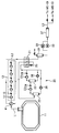
- FIG. 1 is a schematic block diagram for explaining a method for treating boil-off gas through re-liquefaction of boil-off gas according to the prior art
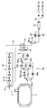
- FIG. 2 is a schematic block diagram for explaining a method for treating boil-off gas through fuel supply according to the present invention
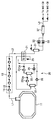
- 3A is a configuration diagram showing a fuel supply system for a high pressure natural gas injection engine according to the first embodiment of the present invention
- 3B is a configuration diagram showing a fuel supply system for a high pressure natural gas injection engine according to a modification of the first embodiment of the present invention
- Figure 4a is a graph showing the freezing point and boiling point of the components contained in the non-explosive mixed refrigerant of the present invention
- Figure 4b is a graph showing the freezing point and boiling point of the components contained in the hydrocarbon mixed refrigerant
- Figure 4c is a graph showing the liquefaction temperature according to the pressurized pressure of natural gas
- 6a to 6c are for comparing the power consumption when using the nitrogen gas refrigeration cycle in the reliquefaction apparatus of the boil-off gas, when using a non-explosive mixed refrigerant refrigeration cycle, and when using a Single Mixed Refrigerant (SMR) refrigeration cycle Graphs,
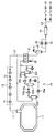
- FIG. 7A is a configuration diagram showing a fuel supply system for a high pressure natural gas injection engine according to a second embodiment of the present invention.
- FIG. 7B is a block diagram showing a fuel supply system for a high pressure natural gas injection engine according to a modification of the second embodiment of the present invention.
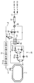
- FIG. 8A is a block diagram showing a fuel supply system for a high pressure natural gas injection engine according to a third embodiment of the present invention.
- FIG. 8B is a block diagram showing a fuel supply system for a high pressure natural gas injection engine according to a modification of the third embodiment of the present invention.
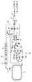
- 9A is a configuration diagram showing a fuel supply system for a high pressure natural gas injection engine according to a fourth embodiment of the present invention.
- 9B is a configuration diagram showing a fuel supply system for a high pressure natural gas injection engine according to a modification of the fourth embodiment of the present invention.
- FIG. 10A is a block diagram showing a fuel supply system for a high pressure natural gas injection engine according to a fifth embodiment of the present invention.
- 10B is a block diagram showing a fuel supply system for a high pressure natural gas injection engine according to a modification of the fifth embodiment of the present invention.
- FIG. 11 is a configuration diagram showing a fuel supply system for a high pressure natural gas injection engine according to a sixth embodiment of the present invention.
- Such ME-GI engines are marine structures such as LNG carriers for storing and transporting LNG (Liquefied Natural Gas) in cryogenic storage tanks (including marine vessels, LNG carriers, LNG RV, etc.) It can be installed in a marine plant such as LNG FPSO and LNG FSRU.)
- LNG Liquefied Natural Gas
- cryogenic storage tanks including marine vessels, LNG carriers, LNG RV, etc.
- LNG FPSO and LNG FSRU natural gas
- high pressure about 150 ⁇ 400 bara (absolute pressure) depending on the load. Gas supply pressure is required.
- Boil Off Gas (BOG) from LNG storage tanks.
- a reliquefaction device is still needed to treat Boil Off Gas (BOG) from LNG storage tanks.
- BOG Boil Off Gas
- the boil-off gas is changed depending on the change in gas and fuel oil prices and the degree of regulation of exhaust gas.
- HFO heavy fuel oil
- the boil-off gas generated in the storage tank that is, NBOG is supplied to the boil-off gas compressor and compressed to medium pressure of about 12 to 45 bara, and then the medium pressure BOG is mixed refrigerant, for example, non-explosive mixing. It is supplied to a re-liquefaction apparatus using a refrigerant (Non Flammable Mixed Refrigerant), SMR (Single Mixed Refrigerant), or nitrogen as a refrigerant.
- a refrigerant Non Flammable Mixed Refrigerant
- SMR Single Mixed Refrigerant
- the liquefied boil-off gas, LBOG, in the reliquefaction apparatus is compressed to the pressure required by the ME-GI engine in the fuel supply system (high pressure of about 400 bara, for example) and then supplied as fuel to the ME-GI engine.
- the LBOG supplied to the fuel supply system in the reliquefaction apparatus does not return to the storage tank, it is possible to prevent a problem of generating flash gas as in the prior art, and thus, the pressure of the boil-off gas in the evaporative gas compressor. Can be compressed to medium pressure.
- the pressure range of the high pressure means a pressure of about 150 to 400 bara, which is a fuel supply pressure required by the high pressure natural gas injection engine
- the pressure range of the medium pressure means the evaporation in the evaporation gas compression unit 13.
- the pressure ranges from about 12 to 45 bara to compress the gas
- the low pressure means the pressure range from about 4 to 8 bara to compress to supply the boil-off gas to the reliquefaction apparatus in the prior art.
- the reliquefaction after compression in the medium pressure range is conventional in both the case of using a nitrogen refrigerant as in FIGS. 6A and 6B, the use of a non-explosive mixed refrigerant, and the use of SMR as in FIG. 6C.
- 6A and 6B show data obtained using a Hysys process model (manufactured by Aspentech).
- the results show that Hamworthy's Mark III reliquefaction unit (technology described in WO 2007/117148), which uses nitrogen gas as a refrigerant, requires the power required for reliquefaction when the pressure of the boil-off compressor is 8 bara. While the pressure is about 2,776 kPa, the pressure of the boil-off gas compressor rises to 12 bara and rapidly decreases to 2,500 kPa. At pressures above 12 bara, the required power for reliquefaction is gradually reduced.
- the graph shown in FIG. 6C shows a change in power required when a hydrocarbon-based SMR is used as the refrigerant. Looking at the results, it can be seen that even when using the SMR as the refrigerant, the power required for reliquefaction is rapidly reduced when the pressure of the boil-off gas compressor is 12 bara compared to the pressure of the boil-off gas compressor is 8 bara. At pressures above 12 bara, the required power for reliquefaction is gradually reduced.
- composition of SMR was adjusted as shown in Table 1 below to optimize efficiency for each liquefaction pressure.
- the pressure range of the boil-off gas is preferably a medium pressure range, that is, 12 bara to 45 bara. If it is less than 12 bara, the power savings required for reliquefaction are not great, which is not preferable. In addition, when it exceeds 45 bara, compared with the power required for pressurization of the boil-off gas, the energy saving required for reliquefaction is not large, which is not preferable.
- FIG. 3A is a block diagram showing a fuel supply system of an offshore structure, in particular a liquefied natural gas carrier, having a high pressure natural gas injection engine, such as a ME-GI engine, according to a first embodiment of the present invention.
- 3A shows an example in which a fuel supply system for a high pressure natural gas injection engine of the present invention is applied to an LNG carrier equipped with a ME-GI engine capable of using natural gas as a fuel, but for the high pressure natural gas injection engine of the present invention
- the fuel supply system can be applied to all types of offshore structures with liquefied gas storage tanks, namely ships such as LNG carriers, LNG RVs, as well as offshore plants such as LNG FPSOs and LNG FSRUs.
- the boil-off gas (NBOG) generated and discharged from the liquefied gas storage tank 11 is the boil-off gas compression unit 13.
- the liquefied liquefied gas (LBOG) which is supplied with liquefied energy, that is, cold heat from the reliquefaction apparatus 20, is compressed to a high pressure of about 150 to 400 bara by a high pressure pump 33, and then, to the high pressure vaporizer 37. Supplied.
- the boil-off gas vaporized in the high pressure vaporizer 37 is subsequently supplied as fuel to a high pressure natural gas injection engine, such as a ME-GI engine.
- the liquefied evaporation gas (ie, liquefied natural gas) compressed to a high pressure by the high pressure pump 33 is in a supercritical pressure state, and thus it is virtually indistinguishable from liquid phase and gas phase.
- it is expressed as vaporizing the heating of the liquefied evaporation gas to the ambient temperature (or the temperature required by the high-pressure natural gas injection engine) in the high pressure state
- the high-pressure device for heating the liquefied evaporation gas to the ambient temperature in the high pressure state Express it as a carburetor.
- Storage tanks are equipped with sealed and insulated barriers to store liquefied gases, such as LNG, in cryogenic conditions, but they cannot completely block heat from the outside. Accordingly, the liquefied gas is continuously evaporated in the storage tank 11, and the evaporated gas is discharged through the evaporated gas discharge line L1 to maintain the pressure of the evaporated gas at an appropriate level. Let's do it.
- the discharged boil-off gas is supplied to the boil-off gas compression unit 13 through the boil-off gas discharge line L1.
- the boil-off gas compressor 13 includes one or more boil-off gas compressors 14 and one or more intermediate coolers 15 for cooling the boil-off gas whose temperature has risen while being compressed by the boil-off gas compressor 14.
- FIG. 3A there is illustrated a 5-stage compressed boil-off gas compression unit 13 comprising five boil-off gas compressors 14 and five intermediate coolers 15.
- the boil-off gas compressed by the boil-off gas compression unit 13 is supplied to the reliquefaction apparatus 20 through the boil-off gas supply line L2.
- the boil-off gas supplied to the reliquefaction apparatus 20 is cooled by the refrigerant and reliquefied while passing through the cold box 21 of the reliquefaction apparatus 20.
- any structure can be used as long as it can liquefy evaporated gas generated from liquefied gas such as LNG.
- the evaporated gas re-liquefied through heat exchange in the cold box 21 is separated into a gas and a liquid state in the buffer tank 31, and only the liquid liquefied evaporation gas in the liquid state is supplied to the high pressure pump 33 through the fuel supply line L3. Is supplied.
- the high pressure pump 33 may be provided in plural, for example two in parallel.
- liquefied evaporation gas is pressurized to a fuel supply pressure required by a high pressure natural gas injection engine (for example, a ME-GI engine) and sent out.
- the liquefied evaporation gas sent from the high pressure pump 33 has a high pressure of about 150 to 400 bara (absolute pressure).
- the reliquefaction apparatus 20 illustrated in FIG. 3A includes a cold box 21 for reliquefying the boil-off gas by heat exchange between the refrigerant and the boil-off gas, and a refrigerant partially heated and vaporized in the cold box 21.
- At least one refrigerant gas-liquid separator 22 for separating gaseous and liquid refrigerants
- at least one refrigerant compressor 23 for compressing the gaseous refrigerant separated from the refrigerant gas-liquid separator 22
- a refrigerant cooler 24 for cooling the refrigerant compressed by the refrigerant compressor 23, and a refrigerant expansion valve 25 for expanding the refrigerant cooled in the refrigerant cooler 24 after being compressed by the refrigerant compressor 23 to lower the temperature.
- a refrigerant pump 26 for supplying the refrigerant in the liquid state separated from the refrigerant gas-liquid separator 22 to the refrigerant expansion valve 25.
- the refrigerant supplied to the refrigerant expansion valve 25 through the refrigerant pump 26 is mixed with the refrigerant supplied to the refrigerant expansion valve 25 after passing through the refrigerant cooler 24 upstream of the refrigerant expansion valve 25. It is preferable.
- the refrigerant supplied to the refrigerant expansion valve 25 may be configured to exchange heat with the refrigerant in the cryogenic state after expansion while passing through the cold box 21 before expansion.
- the refrigerant cooled in the refrigerant cooler 24 may be supplied to another refrigerant gas-liquid separator to be processed into a refrigerant in a gas state and a refrigerant in a liquid state.
- the reliquefaction apparatus 20 of FIG. 3A is illustrated as including two refrigerant gas-liquid separators 22, a refrigerant compressor 23, a refrigerant cooler, and a refrigerant pump 26, but this is intended to explain the present invention. It is not limited and the number of installations can be added or subtracted as needed in the design.
- 3b shows a fuel supply system according to a variant of the first preferred embodiment of the invention. Since the structure of the boil-off gas compression part 13 and the reliquefaction apparatus 20 differs in part from the 1st embodiment mentioned above in the modified example of this 1st embodiment, only the difference is demonstrated below.
- the boil-off gas compression section 13 according to the modification of the first embodiment illustrated in FIG. 3B is the same as that shown in FIG. 3A in that it has five boil-off gas compressors 14, but the boil-off gas compression section ( 3A differs from that illustrated in FIG. 3A in that the intermediate cooler 15 is omitted between the first and second boil-off compressors and between the second and third boil-off compressors included in 13). Do. According to the present invention, the intermediate cooler 15 may or may not be disposed between the boil-off compressors 14 as described above.
- the reliquefaction apparatus 20 which concerns on the modification of this 1st Embodiment illustrated in FIG. 3B is the cold box 21 which heat-exchanges a refrigerant
- the reliquefaction apparatus 20 includes a cold box 21 for reliquefying the boil-off gas by heat exchange between the refrigerant and the boil-off gas,
- the first refrigerant gas-liquid separator 22a for separating the partially vaporized refrigerant heated in the cold box 21 into a gaseous refrigerant and a liquid refrigerant, and separated from the first refrigerant gas-liquid separator 22a.
- a first refrigerant compressor 23a for compressing the gaseous refrigerant
- a first refrigerant cooler 24a for cooling the refrigerant compressed in the first refrigerant compressor 23a
- the first refrigerant cooler 24a for refrigerant compressed in the first refrigerant compressor 23a.
- the second refrigerant gas-liquid separator 22b for secondarily separating the refrigerant cooled in the gaseous state and the liquid state refrigerant, and the gaseous refrigerant separated in the second refrigerant gas-liquid separator 22b are compressed.
- Second refrigerant compressor (23b) and the second refrigerant compressor (2) The first refrigerant pump for supplying the second refrigerant cooler 24b for cooling the refrigerant compressed by 3b) and the liquid refrigerant separated in the first refrigerant gas-liquid separator 22a to the second refrigerant cooler 24b.
- the second refrigerant pump 26b for supplying the liquid refrigerant separated in the second refrigerant gas-liquid separator 22b to the second refrigerant cooler 24b and the second refrigerant cooler 24b.
- the third refrigerant gas-liquid separator 22c for separating the refrigerant into gaseous and liquid refrigerants, and the liquid refrigerant separated by the third refrigerant gas-liquid separator 22c to expand the temperature.
- a third refrigerant pump 26c for supplying the refrigerant in the liquid state to the refrigerant expansion valve 25 from the third refrigerant gas-liquid separator 22c.
- the liquid refrigerant supplied to the second refrigerant cooler 24b from the first and second refrigerant gas-liquid separators 22a and 22b is joined and then supplied from the second refrigerant compressor 23b to the second refrigerant cooler 24b.
- the second refrigerant cooler 24b may be supplied to the second refrigerant cooler 24b in a mixed state with the gaseous refrigerant.
- the gaseous refrigerant separated from the third gas-liquid separator 22c may be mixed with the liquid refrigerant supplied to the refrigerant expansion valve 25 by the third refrigerant pump 26c.
- the refrigerant supplied to the refrigerant expansion valve 25 may be configured to exchange heat with the refrigerant in the cryogenic state after expansion while passing through the cold box 21 before expansion.
- the reliquefaction apparatus 20 of FIG. 3B is merely an example and does not limit the present invention, and the configuration of the reliquefaction apparatus may be changed as necessary in design.
- a non-explosive mixed refrigerant including R14 may be used unlike the conventional art.
- the non-explosive mixed refrigerant formed by mixing a plurality of non-explosive refrigerants has a mixed composition ratio such that the non-explosive mixed refrigerant does not condense even at the liquefaction temperature when re-liquefying the compressed boil-off gas at medium pressure.
- the refrigeration cycle using the phase change of the mixed refrigerant is more efficient than the nitrogen gas refrigeration cycle using only nitrogen as a refrigerant.
- Conventional mixed refrigerants have a problem in safety due to the mixing of explosive refrigerant, but the non-explosive mixed refrigerant of the present invention is high in safety because it is a mixture of non-explosive refrigerant.
- the non-explosive mixed refrigerant of the present invention it is possible to apply the mixed refrigerant Joule-Thomson refrigeration cycle to the marine LNG reliquefaction apparatus.
- this mixed refrigerant is a hydrocarbon (Hydro-Carbon; hereinafter referred to as "HC”) mixed refrigerant and has difficulty in handling.
- the non-explosive mixed refrigerant of the present invention is composed of argon, hydrofluorocarbon (hereinafter referred to as "HFC”) refrigerant, and fluorocarbon (hereinafter referred to as "FC”) refrigerant, which is explosive There is no
- HFC / FC refrigerant those shown in Table 2 may be used.
- Table 2 shows argon together.
- the freezing point is higher than the general temperature of LNG ( ⁇ 163 ° C.) and thus cannot be used as a refrigerant during LNG reliquefaction.
- the inventors pay attention to the fact that the liquefaction (or reliquefaction) temperature rises as the pressure of the natural gas (or evaporated gas) increases, as shown in FIG. 4C, and thus a highly efficient and safe HFC / FC mixed refrigerant.
- a non-explosive mixed refrigerant has been developed to reliquefy the boil-off gas from LNG storage tanks in offshore structures by Joule-Thomson refrigeration cycle.
- the boil-off gas before the reliquefaction of the boil-off gas by pressurizing to a medium pressure of 12 to 45 bara, the boil-off gas at a temperature higher than the temperature of the boil-off liquid reliquefaction at normal pressure, that is, higher than the freezing point of the non-explosive mixed refrigerant Allow reliquefaction of
- Non-explosive mixed refrigerant of the present invention the boiling point is evenly distributed between natural gas liquefaction temperature (or evaporation gas reliquefaction temperature) and room temperature is made by mixing the refrigerant of various components to use a wide phase change section. It is preferable to classify the refrigerants having similar boiling points into five series, and to select one or more components from each series to constitute the non-explosive mixed refrigerant of the present invention. That is, the non-explosive mixed refrigerant of the present invention is made by selecting and mixing at least one component from each of five series.
- Series I includes Ar having the lowest boiling point among refrigerants
- Series II includes R14
- Series III includes R23, R116, and R41
- Series IV includes R32, R410A , R410B, R125, R143a, R507, R407B, R404A, R407A, R407C, R407E, R407D, R161, R218, R134a, R152a, and R227ea
- Series V include R236fa and R245fa.
- the non-explosive mixed refrigerant of the present invention in which at least one refrigerant is selected from each of these five series has a component and a composition as shown in the following Table 4 in view of ease of supply of refrigerant, cost, and the like.
- the composition ratio of the non-explosive mixed refrigerant is a temperature difference between the heat exchanger that exchanges heat with the boil-off gas, that is, the hot fluid (ie, the boil-off gas) in the cold box 21 and the low-temperature fluid (that is, the non-explosive mixed refrigerant). It is desirable in terms of efficiency to be determined to be as constant as possible.
- Table 4 Ingredient Composition (% mole) Ar 20 to 55 R14 15 to 30 R23 5 to 15 R410a 10 to 15 R245fa 15 to 20
- power consumption that is, power (kW) can be reduced as compared to when the evaporated gas is reliquefied using nitrogen gas refrigerant as in the prior art, thereby improving reliquefaction efficiency.
- the present invention compresses and reliquefies the evaporated gas to a medium pressure of about 12 to 45 bara, which is a relatively high pressure, compared to the evaporated gas pressure used in the conventional reliquefaction apparatus, when reliquefying
- the reliquefaction efficiency in the reliquefaction apparatus is best when the evaporated gas has a pressure of about 12 to 45 bara. I can keep it.
- the reliquefaction temperature is about -130 ° C
- the temperature of the non-explosive mixed refrigerant is lowered to about -155 ° C in order to cool the boil-off gas to this temperature. Since the non-explosive mixed refrigerant having the composition may cause freezing at -155 ° C. or lower, a refrigeration cycle using the non-explosive mixed refrigerant is difficult to configure when the pressure of the boil-off gas is lower than 12 bara.
- the present invention is characterized by a medium pressure, that is, a pressure range of 12 to 45 bara (based on 4.3 ton / h of evaporating gas), so that both nitrogen gas refrigerants and non-explosive mixed refrigerants are effective.
- a medium pressure that is, a pressure range of 12 to 45 bara (based on 4.3 ton / h of evaporating gas)
- both nitrogen gas refrigerants and non-explosive mixed refrigerants are effective.
- the reliquefaction apparatus using the non-explosive mixed refrigerant having the composition as described above of the present invention further reduces power by approximately 10 to 20%.
- FIG. 6B shows the power requirement in the conditions of the reliquefaction apparatus according to the prior art (i.e., when the refrigerant used in the reliquefaction apparatus is nitrogen gas (N2) and the pressure of the boil-off gas supplied to the reliquefaction apparatus is 8 bara).
- the conditions of the reliquefaction apparatus using the non-explosive mixed refrigerant (NFMR) according to the present invention ie, the refrigerant used in the reliquefaction apparatus is a non-explosive mixed refrigerant (NFMR) and the pressure of the boil-off gas supplied to the reliquefaction apparatus is A graph comparing the power requirements (in the case of 12 to 45 bara) is shown. Referring to FIG.
- the reliquefaction apparatus of the present invention can operate with only about 50 to 80% of the power compared to the power consumed in the conventional reliquefaction apparatus (refrigeration cycle) using nitrogen refrigerant.
- the generator capacity can be reduced and the generator can be miniaturized.
- the reliquefaction apparatus of the present invention uses a Joule Thomson valve as an expansion means of the refrigerant, so that the entire system is simpler and more economical than the conventional N2 compander using an expander. You can get the advantage.
- non-explosive mixed refrigerant of the present invention may contain a small amount of non-explosive refrigerant components other than those shown in Table 2.
- FIG. 7A is a block diagram showing a fuel supply system for an offshore structure having a high pressure natural gas injection engine (eg, a ME-GI engine) according to a second embodiment of the present invention.
- FIG. 7A The fuel supply system of the second embodiment shown in FIG. 7A has a high pressure pump 33 before compressing the boil-off gas to medium pressure and re-liquefying in the reliquefaction apparatus as compared with the fuel supply system of the first embodiment described above. Since they differ from each other only in that they are pre-cooled by heat exchange with LNG supplied to the high-pressure vaporizer 37, the following description focuses on differences from the first embodiment.
- the liquefied evaporated gas compressed at high pressure in the high pressure pump 33 is supplied to the reliquefaction apparatus 20 and the heat exchanger 35 to be supplied to the reliquefaction apparatus 20 before being supplied to the high pressure vaporizer 37.
- the liquefied evaporation gas supplied to the high pressure vaporizer 37 may be heated while passing through the heat exchanger 35 to reduce the vaporization energy of the high pressure vaporizer 37.
- the boil-off gas compressed by the boil-off gas compression unit 13 is supplied to the reliquefaction apparatus 20 through the boil-off gas supply line L2.
- a heat exchanger 35 is installed in the middle of the boil-off gas supply line L2. As described above, the relatively low-temperature compressed boil-off gas discharged from the high-pressure pump 33 and the compressed high-temperature pump 33 in the heat exchanger 35 are installed. Liquefied evaporation gases exchange heat with each other.
- the boil-off gas cooled while passing through the heat exchanger 35 is cooled by the refrigerant and re-liquefied while passing through the cold box 21 of the reliquefaction apparatus 20.
- FIG. 7B shows a fuel supply system according to a modification of the second preferred embodiment of the present invention.
- the modification of this 2nd Embodiment is partially different from the 2nd Embodiment mentioned above in the structure of the boil-off gas compression part 13 and the reliquefaction apparatus 20 as demonstrated in the modification of 1st Embodiment. Do.
- the boil-off gas compression unit 13 according to the modification of the second embodiment illustrated in FIG. 7B has the same as that shown in FIG. 7A in that it has five boil-off gas compressors 14, the boil-off gas compression 7a in that the intermediate cooler 15 is omitted between the first and second boil-off compressors, and between the second and third boil-off compressors included in section 13. Is different from According to the present invention, the intermediate cooler 15 may or may not be disposed between the boil-off compressors 14 as described above.
- the reliquefaction apparatus 20 which concerns on the modification of this 2nd Embodiment illustrated in FIG. 7B is similar to the reliquefaction apparatus 20 which concerns on the modification of 1st Embodiment illustrated in FIG. Cold box 21 through which heat exchange of the boil-off gas is performed, compression means for compressing at least partially vaporized refrigerant heated in the cold box 21, expansion means for expanding the compressed refrigerant to lower the temperature, and gas And a refrigerant gas-liquid separator for separating the refrigerant in the liquid state and the refrigerant in the liquid state.
- the reliquefaction apparatus 20 includes a plurality of refrigerant gas-liquid separators 22a, 22b, and 22c, as in FIG. 2B.
- the refrigerant gas-liquid separator 22c disposed on the downstream side among the refrigerant gas-liquid separators of the refrigerant gas-liquid separator 22c is supplied after mixing the refrigerant in the gas state and the liquid state in the refrigerant gas-liquid separators 22a and 22b disposed upstream. .
- the gaseous refrigerant separated in the refrigerant gas-liquid separators 22a and 22b disposed on the upstream side is compressed by the refrigerant compressors 23a and 23b before being supplied to the refrigerant gas-liquid separator 22c disposed on the downstream side. And cooled by the refrigerant coolers 24a and 24b.
- the liquid refrigerant separated in the refrigerant gas-liquid separators 22a and 22b disposed on the upstream side is more specifically, a gas before the gaseous refrigerant is supplied to the refrigerant gas-liquid separator 22c disposed on the downstream side.
- the refrigerant in the state is mixed with the gaseous refrigerant before being cooled by the refrigerant cooler 24b.
- FIG. 8A is a block diagram showing a fuel supply system of an offshore structure having a high pressure natural gas injection engine (for example, a ME-GI engine) according to a third embodiment of the present invention.
- the fuel supply system of the third embodiment shown in FIG. 8A differs from each other only in that it preheats before compressing the boil-off gas as compared with the fuel supply system of the first embodiment described above, and therefore, in the following description, The differences are explained mainly.
- the boil-off gas (NBOG) generated and discharged from the liquefied gas storage tank 11 is discharged. Is compressed to a medium pressure of about 12 to 45 bara (absolute pressure) in the boil-off gas compression unit 13, and then the boil-off gas installed upstream of the boil-off gas compression unit 13 before being supplied to the reliquefaction apparatus 20. It is supplied to the preheater 41.
- the boil-off gas compressed to about 12 to 45 bara in the boil-off gas compression unit 13 and cooled to about 40 ° C. through the intermediate cooler 15 is cryogenically discharged from the liquefied gas storage tank 11 in the boil-off gas preheater 41. It is cooled by heat exchange with the boil-off gas and then supplied to the reliquefaction apparatus 20.
- the temperature of the boil-off gas to be supplied to the reliquefaction apparatus 20 can be lowered through the boil-off gas preheater 41, thereby reducing the heat load in the cold box 21.
- the cryogenic gas supplied to the boil-off gas compression unit 13 and the boil-off gas having a relatively high temperature compressed by the boil-off gas compression unit 13 are located upstream of the boil-off gas compression unit 13.
- the boil-off gas which has been compressed by the boil-off gas compression section 13 and passed through the boil-off gas preheater 41, is supplied to the reliquefaction apparatus 20 similarly to the fuel supply system of the first embodiment described above. Subsequently, the liquefied liquefied gas (LBOG) supplied with liquefied energy, that is, cold heat from the reliquefaction apparatus 20 is compressed to a high pressure of about 150 to 400 bara by the high pressure pump 33, and then a high pressure vaporizer ( 37). The boil-off gas vaporized in the high pressure vaporizer 37 is subsequently supplied as fuel to a high pressure natural gas injection engine, such as a ME-GI engine.
- a high pressure natural gas injection engine such as a ME-GI engine.
- FIG. 8B shows a fuel supply system according to a modification of the third preferred embodiment of the present invention.
- the modification of this 3rd Embodiment differs in part from the structure of the reliquefaction apparatus 20 compared with 3rd Embodiment mentioned above.
- the reliquefaction apparatus 20 which concerns on the modification of this 3rd embodiment illustrated in FIG. 8B is similar to the reliquefaction apparatus 20 which concerns on the modification of the 1st embodiment illustrated in FIG. Cold box 21 through which heat exchange of the boil-off gas is performed, compression means for compressing at least partially vaporized refrigerant heated in the cold box 21, expansion means for expanding the compressed refrigerant to lower the temperature, and gas And a refrigerant gas-liquid separator for separating the refrigerant in the liquid state and the refrigerant in the liquid state.
- the reliquefaction apparatus 20 includes a plurality of refrigerant gas-liquid separators 22a, 22b, and 22c, as in FIG. 2B.
- the refrigerant gas-liquid separator 22c disposed on the downstream side among the refrigerant gas-liquid separators of the refrigerant gas-liquid separator 22c is supplied after mixing the refrigerant in the gas state and the liquid state in the refrigerant gas-liquid separators 22a and 22b disposed upstream. .
- the gaseous refrigerant separated in the refrigerant gas-liquid separators 22a and 22b disposed on the upstream side is compressed by the refrigerant compressors 23a and 23b before being supplied to the refrigerant gas-liquid separator 22c disposed on the downstream side. And cooled by the refrigerant coolers 24a and 24b.
- the liquid refrigerant separated in the refrigerant gas-liquid separators 22a and 22b disposed on the upstream side is more specifically, a gas before the gaseous refrigerant is supplied to the refrigerant gas-liquid separator 22c disposed on the downstream side.
- the refrigerant in the state is mixed with the gaseous refrigerant before being cooled by the refrigerant cooler 24b.
- FIG. 9A is a block diagram showing a fuel supply system of an offshore structure having a high pressure natural gas injection engine (for example, a ME-GI engine) according to a fourth embodiment of the present invention.
- the fuel supply system of the fourth embodiment shown in FIG. 9A is more stable than the fuel gas supply system of the third embodiment described above, that is, surplus boil-off gas consumption means for treating surplus boil-off gas, that is, a heterogeneous fuel engine (DFDE) or the like. Since the means for supplying fuel, that is, the LNG supply line is different from each other, the following description focuses on differences from the second embodiment.
- DFDE heterogeneous fuel engine
- the excess evaporation gas means more evaporation gas than the amount of liquefied evaporation gas required by the high-pressure gas injection engine. If excess evaporated gas is generated, the amount of generated evaporated gas is high even if the high-pressure gas injection engine is in operation, or if the high-pressure gas injection engine operates at low speed or does not operate (for example, when entering a port or opening a canal). May occur).
- the excess liquefied vaporization gas The LBOG is depressurized through the LBOG expansion valve 51 installed at the LBOG return line L4 branching from the fuel supply line L3 at the rear end of the buffer tank 31, and includes flash gas generated in the depressurization process. After the LBOG is separated into a liquid component (LBOG) and a gas component (flash gas) through a gas-liquid separator, the liquid component is returned to the storage tank 11 through the LBOG return line L4.
- LBOG liquid component
- flash gas flash gas
- the LBOG containing the flash gas reduced in pressure by the LBOG expansion valve 51 is supplied to the LBOG gas-liquid separator 53 and separated into a liquid component and a gas component, and the gas component separated by the LBOG gas-liquid separator 53.
- a surplus boil-off gas consuming means i.e., a heterogeneous fuel engine DFDE, which can be installed in the offshore structure for power generation or the like through the fuel gas supply line L6.
- the pressure of the fuel gas supplied to the heterogeneous fuel engine can be adjusted by a pressure regulating valve installed downstream of the LBOG gas-liquid separator 53 in the middle of the fuel gas supply line L6, and also the fuel gas supply line ( In the fuel gas heater 55 installed in the middle of L6), the temperature of the fuel gas may be heated to a temperature required by the heterogeneous fuel engine.
- the liquid component separated in the LBOG gas-liquid separator 53 is returned to the storage tank through the LBOG return line (L4).
- the pressure of the liquid component separated in the LBOG gas-liquid separator 53 may still be higher than the normal pressure.
- the liquid component separated from the LBOG gas-liquid separator 53 i.e., LBOG
- LBOG liquid component separated from the LBOG gas-liquid separator 53
- another LBOG gas-liquid separator 54 is further depressurized through another LBOG expansion valve 52, and is then supplied to another LBOG gas-liquid separator 54 to supply the liquid component ( After separating into LBOG) and a gas component (flash gas), the liquid component of normal pressure is returned to the storage tank 11 through the LBOG return line L4.
- the gas component separated in another LBOG gas-liquid separator 54 may be consumed by being supplied to and combusted by a gas combustion unit (GCU) as another surplus boil-off gas consumption means.
- GCU gas combustion unit
- the fuel supplied to the heterogeneous fuel engine is insufficient, the fuel is diverted from the fuel supply line L3 supplying the fuel to the high pressure natural gas injection engine (ie, ME-GI) to supply fuel to the heterogeneous fuel engine (ie, DFDE).
- Fuel may be additionally supplied to the heterogeneous fuel engine through the branch line L5 connected to the fuel gas supply line L6.
- the branch line (L5) is provided with a valve for the pressure drop.
- the boil-off gas reliquefaction apparatus when the boil-off gas reliquefaction apparatus does not operate or the amount of the boil-off gas generated in the storage tank 11 is small, it is stored through the LNG supply pump 57 and the LNG supply line L7 installed in the storage tank 11. Fuel can be supplied by supplying LNG accommodated in the tank 11 to the buffer tank 31.
- the heterogeneous fuel engine functions as a flash gas treating means capable of treating flash gas generated from the LBOG on the way back to the storage tank 11 due to the pressure difference.
- the gas component separated in the LBOG gas-liquid separator 53 may be supplied to a consumer such as a gas turbine, a boiler or the like instead of a heterogeneous fuel engine, and may be used as fuel.
- this gas component can be supplied to and treated by a gas discharge device for releasing natural gas into the atmosphere, or a gas combustion device (for example, a flare tower) for burning in the atmosphere.
- the heterogeneous fuel engine, gas turbine, boiler, gas discharge device or flare tower is included in the surplus evaporative gas consumption means (flash gas processing means), the gas component supplied to such surplus evaporative gas consumption means is a fuel gas heater ( 55).
- the evaporated gas supplied to the reliquefaction apparatus is compressed to a medium pressure of about 12 to 45 bara. Can be supplied, thereby reducing the energy consumption of reliquefaction.
- FIG. 9B shows a fuel supply system according to a modification of the fourth preferred embodiment of the present invention.
- the modified example of the fourth embodiment is partially different from the above-described fourth embodiment in the configuration of the reliquefaction apparatus 20, and from the evaporative gas compression unit 13 or downstream thereof when excess evaporated gas is generated. It is different from the fourth embodiment in that the excess boil-off gas is treated through a line branching at the side end.
- the reliquefaction apparatus 20 according to the modification of the fourth embodiment illustrated in FIG. 9B is similar to the reliquefaction apparatus 20 according to the modification of the first embodiment illustrated in FIG. 2B.
- a cold box 21 in which heat exchange is performed compression means for compressing at least partially vaporized refrigerant heated in the cold box 21, expansion means for expanding the compressed refrigerant to lower the temperature, and a gaseous state.
- Refrigerant gas-liquid separator for separating the refrigerant and the liquid refrigerant.
- the reliquefaction apparatus 20 includes a plurality of refrigerant gas-liquid separators 22a, 22b, and 22c as in FIG. 2B.
- the refrigerant gas-liquid separator 22c disposed on the downstream side among the refrigerant gas-liquid separators of the refrigerant gas-liquid separator 22c is supplied after mixing the refrigerant in the gas state and the liquid state in the refrigerant gas-liquid separators 22a and 22b disposed upstream. .
- the gaseous refrigerant separated in the refrigerant gas-liquid separators 22a and 22b disposed on the upstream side is compressed by the refrigerant compressors 23a and 23b before being supplied to the refrigerant gas-liquid separator 22c disposed on the downstream side. And cooled by the refrigerant coolers 24a and 24b.
- the liquid refrigerant separated in the refrigerant gas-liquid separators 22a and 22b disposed on the upstream side is more specifically, a gas before the gaseous refrigerant is supplied to the refrigerant gas-liquid separator 22c disposed on the downstream side.
- the refrigerant in the state is mixed with the gaseous refrigerant before being cooled by the refrigerant cooler 24b.
- the fuel supply system according to the modification of the fourth embodiment illustrated in FIG. 9B is surplus through the second branch line L8 branching from the boil-off gas compression unit 13 when more boil-off gas is generated than the required amount. It can be configured to supply and use the boil-off gas to a different fuel engine (DFDE) as a surplus boil-off gas consumption means.
- DFDE fuel engine
- the temperature of the boil-off gas in the intermediate cooler 15 included in the boil-off gas compression unit 13 is cooled to about 40 ° C., a separate heater or the like for controlling the temperature of the boil-off gas supplied to the different fuel engine is May be omitted.
- the surplus evaporated gas may be configured to be supplied to the gas turbine as another surplus evaporated gas consumption means through a third branch line L9 branching from the rear end of the evaporated gas compression unit 13.
- a separate device for controlling the temperature of the boil-off gas supplied to the gas turbine may be omitted.
- the fuel supply system according to the modification of the fourth embodiment illustrated in FIG. 9B is composed of one LBOG expansion valve and one LBOG gas-liquid separator disposed in the LBOG return line L4, respectively, as compared with the fourth embodiment described above.
- another LBOG expansion valve 52 and LBOG gas-liquid separator 54 may be additionally arranged as necessary in the fourth embodiment.
- FIG. 10A is a block diagram showing a fuel supply system of an offshore structure having a high pressure natural gas injection engine (for example, a ME-GI engine) according to a fifth embodiment of the present invention.
- the fuel supply system of the fifth embodiment shown in FIG. 10A is more stable than the fuel supply system of the third embodiment described above, ie, a means for consuming excess evaporated gas, that is, a gas combustion unit (GCU) or the like. They differ from each other in that means for fuel supply, ie LNG supply lines, have been added.
- GCU gas combustion unit
- the load of the high pressure natural gas injection engine is reduced or the amount of generated evaporated gas is large, so that the excess liquefied vaporization gas (LBOG) ) Is expected to occur, the evaporated gas compressed in the boil-off gas compression section 13 is branched through the branch line and used in the excess boil-off gas consumption means.
- LBOG liquefied vaporization gas
- it may be configured to supply and use the surplus evaporated gas to the heterologous fuel engine DFDE as the surplus evaporated gas consumption means through the second branch line L8 branched from the evaporated gas compression unit 13.
- the temperature of the boil-off gas in the intermediate cooler 15 included in the boil-off gas compression unit 13 is cooled to about 40 ° C., a separate heater or the like for controlling the temperature of the boil-off gas supplied to the different fuel engine is May be omitted.
- the surplus evaporated gas may be configured to be supplied to the gas turbine as another surplus evaporated gas consumption means through a third branch line L9 branching from the rear end of the evaporated gas compression unit 13.
- a separate device for controlling the temperature of the boil-off gas supplied to the gas turbine may be omitted.
- the excess evaporated gas is depressurized through the LBOG expansion valve 51 installed in the LBOG return line L4 branching from the fuel supply line L3 at the rear end of the buffer tank 31, and is generated during the depressurization process.
- the LBOG containing the flash gas is separated into a liquid component (LBOG) and a gas component (flash gas) through the LBOG gas-liquid separator 53
- the liquid component is returned to the storage tank 11 through the LBOG return line L4.
- the gas component (i.e., flash gas) separated in the LBOG gas-liquid separator 53 is supplied as fuel to the gas combustion unit GCU as the surplus boil-off gas consumption means via the fuel gas supply line L6.
- the excess evaporated gas is branched from the fuel supply line (L3) for supplying fuel to the high-pressure natural gas injection engine (ie, ME-GI) and connected to the fuel gas supply line (L6). It can be supplied in addition to the GCU.
- the branch line (L5) is provided with a valve for the pressure drop.
- the LNG supply pump 57 installed in the storage tank 11 and Fuel may be supplied by supplying LNG contained in the storage tank 11 to the buffer tank 31 through the LNG supply line L7.
- devices such as DFDE (fourth embodiment) and GCU (fifth embodiment) described as means for treating the generated flash gas, and no flash gas are generated.
- the devices such as the DFDE (fifth embodiment) and the gas turbine (fifth embodiment), which are described as means for pre-consuming excess evaporated gas before reliquefaction, are all capable of suppressing the generation of flash gas. It can be named as gas suppression means.
- these apparatuses can consume surplus evaporative gas more than the quantity of fuel required by a high pressure gas injection engine, it can also be named as a surplus evaporative gas consumption means.
- FIG. 10B shows a fuel supply system according to a modification of the fifth preferred embodiment of the present invention.
- the configuration of the reliquefaction apparatus 20 is partially different from that of the fifth embodiment described above.
- the reliquefaction apparatus 20 which concerns on the modification of this 5th embodiment illustrated in FIG. 10B is the same as that of the reliquefaction apparatus 20 which concerns on the modification of the 1st embodiment illustrated in FIG. Cold box 21 through which heat exchange of the boil-off gas is performed, compression means for compressing at least partially vaporized refrigerant heated in the cold box 21, expansion means for expanding the compressed refrigerant to lower the temperature, and gas And a refrigerant gas-liquid separator for separating the refrigerant in the liquid state and the refrigerant in the liquid state.
- the reliquefaction apparatus 20 includes a plurality of refrigerant gas-liquid separators 22a, 22b, and 22c, as in FIG. 2B.
- the refrigerant gas-liquid separator 22c disposed on the downstream side among the refrigerant gas-liquid separators of the refrigerant gas-liquid separator 22c is supplied after mixing the refrigerant in the gas state and the liquid state in the refrigerant gas-liquid separators 22a and 22b disposed upstream. .
- the gaseous refrigerant separated in the refrigerant gas-liquid separators 22a and 22b disposed on the upstream side is compressed by the refrigerant compressors 23a and 23b before being supplied to the refrigerant gas-liquid separator 22c disposed on the downstream side. And cooled by the refrigerant coolers 24a and 24b.
- the liquid refrigerant separated in the refrigerant gas-liquid separators 22a and 22b disposed on the upstream side is more specifically, a gas before the gaseous refrigerant is supplied to the refrigerant gas-liquid separator 22c disposed on the downstream side.
- the refrigerant in the state is mixed with the gaseous refrigerant before being cooled by the refrigerant cooler 24b.
- FIG. 11 is a configuration diagram showing a fuel supply system for an offshore structure having a high pressure natural gas injection engine (for example, a ME-GI engine) according to a sixth embodiment of the present invention.
- the fuel supply system of the sixth embodiment shown in FIG. 11 is different from each other in that a recondenser is used in place of the buffer tank included in the fuel supply systems of the first to fifth embodiments described above.
- the boil-off gas (NBOG) generated and discharged from the liquefied gas storage tank 110, the boil-off gas compression unit ( In 113) is supplied to the reliquefaction apparatus 120 after being compressed to a medium pressure of approximately 12 to 45 bara (absolute pressure).
- the liquefied liquefied gas (LBOG) which is supplied with liquefied energy, that is, cold heat from the reliquefaction apparatus 120, is compressed to a high pressure of about 150 to 400 bara by the high pressure pump 133, and then, to the high pressure vaporizer 137. Supplied.
- the boil-off gas vaporized in the high pressure vaporizer 137 is subsequently supplied as fuel to a high pressure natural gas injection engine, such as a ME-GI engine.
- Storage tanks are equipped with sealed and insulated barriers to store liquefied gases, such as LNG, in cryogenic conditions, but they cannot completely block heat from the outside. Accordingly, the evaporation of the liquefied gas is continuously performed in the storage tank 110, and in order to maintain the pressure of the evaporated gas at an appropriate level, the evaporated gas is discharged through the evaporated gas discharge line L11 in the storage tank 110. Let's do it.
- the discharged boil-off gas is supplied to the boil-off gas compression unit 113 through the boil-off gas discharge line L11.
- the boil-off gas compressor 113 includes one or more boil-off gas compressors 114. Although not shown, the boil-off gas compressor 113 may include one or more intermediate coolers (not shown) for cooling the boil-off gas whose temperature has risen while being compressed by the boil-off gas compressor 114. In FIG. 11, a three-stage compressed boil-off gas compression unit 113 including three boil-off gas compressors 114 is illustrated.
- the boil-off gas compressed by the boil-off gas compression unit 113 is supplied to the reliquefaction apparatus 120 through the boil-off gas supply line L12.
- the boil-off gas supplied to the reliquefaction apparatus 120 is cooled by the refrigerant and re-liquefied while passing through a cold box of the reliquefaction apparatus 120, that is, the main cryogenic heat exchanger 121.
- any structure can be used as long as it can liquefy evaporated gas generated from liquefied gas such as LNG. That is, a reliquefaction system utilizing a non-explosive mixed refrigerant having a configuration as described in the first to fifth embodiments and modifications thereof described above can be used. In addition, a reliquefaction system utilizing a conventionally known nitrogen refrigerant may be used, and for example, those disclosed in WO 2007/117148 and WO 2009/136793 may be used.
- the boil-off gas liquefied through heat exchange in the cold box 121 is supplied to the recondenser 131 and temporarily stored.
- the liquefied liquefied gas and the liquefied gas supplied from the liquefied gas storage tank 110 that is, LNG is temporarily stored in the recondenser 131, and reliquefied from the liquefied gas storage tank 110.
- the recondenser 131 is directly liquefied in the reliquefaction apparatus 120 and then directly supplied to the recondenser 131 to be temporarily stored in the liquefied evaporation gas and the storage tank 110. Cooling heat from at least one of the liquefied gas (ie, LNG) supplied to 131 is used to recondense some or all of the generated boil-off gas.
- LNG liquefied gas
- the recondenser 131 may perform a function of separating gas and liquid components, similarly to the buffer tank in the above-described embodiments, the liquefied gas temporarily stored in the recondenser 131 is separated into a gas and a liquid state, Only the liquefied gas in the liquid state is supplied to the high pressure pump 133 through the fuel supply line L13.
- the high pressure pump 133 may be provided in plural, for example, two in parallel.
- the liquefied gas is pressurized to a fuel supply pressure required by a high pressure natural gas injection engine (for example, a ME-GI engine) and sent out.
- the liquefied gas sent from the high pressure pump 133 has a high pressure of about 150 to 400 bara (absolute pressure).
- a booster pump is provided between the high pressure pump 133 and the recondenser 131 of the fuel supply line L13 to ensure a sufficient net suction head (NPSH) in the high pressure pump 133.
- NPSH net suction head
- the liquefied gas compressed at high pressure in the high pressure pump 133 is supplied to the reliquefaction apparatus 120 and the heat exchanger before being supplied to the high pressure vaporizer 137.
- the system may be configured to exchange heat at 135. Since the liquefied gas supplied to the high pressure vaporizer 137 is relatively low temperature compared to the boiled gas supplied to the reliquefaction apparatus 120, the temperature of the boiled gas supplied to the reliquefaction apparatus 120 while passing through the heat exchanger 135. Reducing the liquefaction energy in the reliquefaction apparatus 120 can be reduced.
- the liquefied gas supplied to the high pressure vaporizer 137 may be heated while passing through the heat exchanger 135 to reduce the vaporization energy of the high pressure vaporizer 137.
- the liquefied evaporated gas recondensed and temporarily stored in the recondenser 131 may be returned to the liquefied gas storage tank 110 through the LBOG return line L14, if necessary.
- the LBOG return line L14 may be provided with expansion valves, gas-liquid separators, and the like as the fourth and fifth embodiments and modified examples thereof described with reference to FIGS. 9A to 10B.
- the vaporized gas generated in the storage tank is liquefied and all are used as fuel in the high pressure natural gas injection engine. Accordingly, the liquefied gas returned to the storage tank 110 through the LBOG return line (L14) can be eliminated.
- the LBOG return line (L14) is used when the towing of the offshore structure in the port, when passing through the canal, or when operating at low speed, the fuel consumption of the high pressure natural gas injection engine Only in very exceptional cases, less than the amount, can be used to return the LBOG from the recondenser 131 to the storage tank 110. In addition, it may be used for the purpose of returning the LBOG remaining in the recondenser 131 to the storage tank 110 during the failure or maintenance of the recondenser.
- the returning LBOG since the LBOG can be used in all engines without returning the LBOG to the storage tank during most of the operation of the offshore structure, the returning LBOG itself can be eliminated during that period, and thus the pressure difference during the return of the LBOG. It is possible to remove the flash gas that may occur due to the source.
- the expression “remove flash gas” means that the flash gas is not supplied to the inside of the storage tank 110 by consuming the generated flash gas, and the reliquefied evaporated gas is stored in the storage tank 110. It is a concept that includes both preventing the return of the flash gas by preventing the return of the flash gas generated during the return.
- the fuel consumption of the high pressure natural gas injection engine is more or less than the amount of boil-off gas generated in the storage tank
- fuel consumption of the high pressure natural gas injection engine is, the high pressure natural gas injection engine
- the fuel consumption of these engines and the fuel consumption of the high pressure natural gas injection engine should be regarded as added.
- the only engine using the boil-off gas as a fuel is a high pressure natural gas injection engine, it means only the fuel consumption of the high pressure natural gas injection engine.
- the LNG contained in the storage tank 110 is directly recondensed through the LNG supply line L17. 131 can be supplied.
- One point of the LNG supply line L17 that is, the starting point of the LNG supply line L17 located inside the liquefied gas storage tank 110 so that LNG contained in the storage tank 110 can be directly supplied to the recondenser 131.
- the submersible pump 157 is installed.
- the internal pressure in the recondenser 131 (or the buffer tank 31 in the first to fifth embodiments and variations thereof) is approximately 12 to 12 in the boil-off gas compression unit 130.
- the booster pump 158 is installed in the middle of the LNG supply line L17, and the pressure inside the recondenser 131 (or buffer tank) is discharged to the outside of the storage tank by the submersible pump 157. It is desirable to compress the pressure to the same level as.
- boil-off gas generated in the liquefied gas storage tank 110 is greater than the amount of fuel required by the high-pressure natural gas injection engine, it is expected that an excess of liquefied liquefied gas (LBOG) will occur.
- the boil-off gas in the middle of being compressed or compressed in stages is branched through the boil-off gas branch line L18 and used in the boil-off gas consumption means.
- a gas turbine, DFDE, or the like which can use natural gas at a lower pressure than fuel as a ME-GI engine, may be used.
- the fuel gas supply system to reduce the load of the reliquefaction apparatus 120 or to completely stop the operation of the reliquefaction apparatus to improve the efficiency of the entire system, evaporation,
- the evaporation gas bypass line (L21) which can be directly supplied to the recondenser 131 by bypassing the reliquefaction apparatus by dividing from the gas supply line (L12) and part or all of the evaporated gas compressed by the evaporation gas compression unit 113 to It may include.
- the boil-off gas bypass line L21 is preferably branched from the heat exchanger 135 downstream of the boil-off gas supply line L12 and connected to the recondenser 131. If necessary, the pressure control valve 161 may be installed in the boil-off gas bypass line L21 to adjust the pressure of the recondenser 131.
- LNG in the storage tank 110 is supplied to the recondenser 131 to compensate for the insufficient fuel amount.
- a part of the boil-off gas supplied to the re-liquefaction apparatus may be supplied to the re-condenser 131 through the boil-off gas bypass line (L21), mixed with LNG, and condensed to reduce the load of the re-liquefaction apparatus.
- the fuel gas supply system includes the recondenser 131, all of the boil-off gas generated in the storage tank 110 is not supplied to the cold box 121 of the reliquefaction apparatus 120.
- the load of the energy consuming reliquefaction apparatus can be reduced, or in some cases, the operation of the reliquefaction apparatus can be completely stopped.
- the boil-off gas discharged from the liquefied gas storage tank 110 is compressed to a medium pressure of about 12 to 45 bara in the boil-off gas compression unit 113 and cooled in the heat exchanger 135, and then the boil-off gas bypass line (L21). Through the total amount is supplied to the recondenser 131.
- the generated boil-off gas may be supplied to the total amount of the recondenser 131 to be recondensed. That is, during the ballast operation, by recondensing all the boil-off gas generated in the storage tank in the recondenser 131 for most of the period, it is possible to stop the operation of the reliquefaction apparatus.
- the high pressure natural gas injection engine is operated at a low speed or stops operating, such as during the towing of offshore structures during ballast operation, the fuel consumption of the high pressure natural gas injection engine may be reduced or significantly reduced. Although all of the gas cannot be recondensed and consumed as fuel, and partially reliquefied in the reliquefaction apparatus, this is a very exceptional case during ballast operation.
- the boil-off gas supplied through the boil-off gas bypass line L21 is mixed with the supercooled LNG in the recondenser 131. In the process of receiving the cold heat from the LNG can be condensed.
- all of the evaporated gas generated in the ballast can be recondensed in the recondenser 131 to be used as fuel in the high-pressure natural gas injection engine, thereby storing the tank 110 There is no LBOG returning to).
- the reliquefaction apparatus 120 since the generated evaporated gas can be processed in the total amount of the recondenser 131, the reliquefaction apparatus 120 that consumes a lot of energy and uses a lot of energy may not be operated at all, thus saving a considerable amount of energy. It becomes possible.
- the re-liquefaction device 120 is operated to re-liquefy the boil-off gas. If necessary, some of the generated boil-off gas may be diverted to the recondenser 131 through the boil-off gas bypass line L21 to reduce energy by reducing the reliquefaction load on the reliquefaction apparatus 120.
- the evaporated gas is compressed to about 12 to 45 bara, and reliquefaction
- the reliquefaction temperature in the apparatus is also running the reliquefaction apparatus at a temperature only approximately 1 ° C. below the saturation temperature at that pressure.
- the reliquefied LBOG since the reliquefied LBOG is not returned to the storage tank, it is not necessary to consider the temperature and pressure of the LNG stored in the storage tank.
- the length of the pipe to transfer the LBOG to the storage tank is relatively long, in the case of the present invention is a relatively short length of the pipe to be transported while maintaining the supercooled state of the LBOG evaporated gas to a temperature too low than the saturation temperature There is no need to overcool it.
- the reliquefaction apparatus 120 by operating the reliquefaction apparatus 120 by setting the liquefaction temperature of the boil-off gas to a temperature slightly lower than the saturation temperature (for example, subcooling only 0.5 to 3 ° C, preferably about 1 ° C). Can be.
- the saturated LBOG due to the pressure increase can then be stably maintained in the supercooled state.
- the fuel supply system of an offshore structure having a high pressure natural gas injection engine according to the first to sixth embodiments of the present invention and its modifications as described above has the following advantages over the prior art.
- the liquefied gas is re-liquefied by the reliquefaction apparatus and returned to the storage tank, and since the LNG stored in the storage tank is maintained at atmospheric pressure, the pressure of the reliquefied liquefied liquefied gas is too high to return to the storage tank.
- the reliquefaction efficiency was low, but the boil-off gas was compressed at a low pressure of about 4 to 8 bara.
- the boil-off gas discharged from the storage tank is used as a fuel in a high-pressure natural gas injection engine, the boil-off gas is compressed and re-liquefied by compressing the boil-off gas to a higher pressure than in the prior art without having to worry about generating a flash gas.
- the liquefaction efficiency can be improved.
- the reliquefied evaporated gas is supplied as a fuel to a high-pressure natural gas injection engine, for example, a ME-GI engine, it is not necessary to return the reliquefied evaporated gas to the storage tank for restoring. It is possible to prevent the generation of flash gas, which can be generated upon return to the furnace, and suppresses the generation of flash gas, thereby compressing the pressure of the boil-off gas to a higher pressure than conventionally, that is, 12 to 45 bara before the reliquefaction. To reliquefy. The reliquefaction efficiency can be improved irrespective of the refrigerant by compressing the evaporated gas to such a medium pressure and reliquefaction.
- the reliquefaction efficiency of the non-explosive mixed refrigerant can be further increased compared to using a nitrogen gas refrigerant. That is, the reliquefaction apparatus of the present invention using a non-explosive mixed refrigerant compared to the conventional nitrogen gas refrigerant can be used to re-liquefy the boil-off gas using a very small amount of energy to supply the engine as fuel.
- any structure can be used as long as it can liquefy evaporated gas generated from liquefied gas such as LNG. That is, a reliquefaction system utilizing a non-explosive mixed refrigerant having a configuration as described in the first to sixth embodiments and modifications thereof described above can be used.
- a reliquefaction system utilizing a conventionally known mixed refrigerant or nitrogen refrigerant may be used, for example, International Patent Publications WO 2007/117148 and WO 2009/136793, Korean Patent Publication No. 2006-0123675 Or those disclosed in Korean Patent Laid-Open No. 2001-0089142 or the like may also be used.
- the liquefied evaporated gas generated in the storage tank is all used as fuel in the high-pressure natural gas injection engine, according to the LBOG return line (L4, L14).
- the LBOG return lines (L4, L14) are used to evaporate the fuel consumption of the high-pressure natural gas injection engine from the storage tank, such as when towing offshore structures to dock in ports, when passing through canals, or when operating at low speeds.
- the LBOG can be used to return the LBOG from the buffer tank 31 or the recondenser 131 to the storage tanks 11 and 110.
- it may be used to return the LBOG remaining in the buffer tank (or recondenser) to the storage tanks 11 and 110 when the buffer tank (or recondenser) is broken or maintained.
- the LBOG can be used in the entire engine without returning the LBOG to the storage tank during most of the operation of the offshore structure, it is possible to eliminate the returning LBOG itself during that period, so that the pressure difference during the return of the LBOG It is possible to remove the flash gas that may occur due to the source.
- the expression "remove flash gas or suppress flash gas generation” in this specification means that the flash gas is not supplied into the storage tank 11 by consuming the generated flash gas, and reliquefied.
- the concept includes all of preventing the generation of flash gas by preventing the evaporated gas from returning to the storage tank 11 and blocking the flash gas generation during the return.
- Hamworthy's Mark III reliquefaction apparatus (as described in WO 2007/117148) liquefies at -159 [deg.] C. by pressurizing the boil-off gas to 8 bara. At this time, since the saturation temperature of the boil-off gas is about -149.5 ° C, about 9-10 ° C is supercooled. This degree of supercooling is required to prevent the generation of flash gas when the liquefied evaporation gas is returned to the LNG storage tank. However, in the present invention, since it is pressurized by a high pressure pump in the process of supplying the liquefied high pressure natural gas injection engine as a fuel, the saturated LBOG may be stably maintained afterwards due to the increase in pressure.
- the liquefied evaporation gas may be cooled by subcooling only 0.5 to 3 ° C, preferably about 1 ° C, than the saturation temperature at the pressure, and then supplied as fuel.
- the fuel supply system of the present invention since it has a concept of basically supplying the re-liquefied LBOG as a fuel to the high-pressure natural gas injection engine, and compresses the boil-off gas to about 12 to 45 bara,
- the reliquefaction temperature of is also operating the reliquefaction apparatus at a temperature of 0.5 to 3 ° C, preferably about 1 ° C lower than the saturation temperature at the pressure.
- the length of the pipe to be transported while maintaining the supercooled state of the LBOG compared to the conventional length of the pipe for transferring the LBOG to the storage tank is relatively long
- the length of the gap is relatively short, and it is not necessary to subcool the boil-off gas to a temperature that is too lower than the saturation temperature.
- the amount of fuel required by the high pressure natural gas injection engine is greater than the amount of boil-off gas generated in the LNG storage tank for a considerable period of time.
- the liquefied gas is supplied to the buffer tank 31. Since it is pressurized by the pump 33, the saturated LBOG due to the pressure increase can then be stably maintained in the supercooled state.
- the flash gas is generated by depressurizing the re-liquefied LBOG into the storage tank, and the flash gas is sent back to the reliquefaction apparatus to reduce the efficiency of the reliquefaction apparatus.
- the efficiency of the reliquefaction apparatus can be improved as compared with the conventional art.
- the reliquefaction apparatus of the present invention can operate with only about 50 to 80% of the power compared to the power consumed in the conventional reliquefaction apparatus (refrigeration cycle). have.
- the generator capacity can be reduced, so that the generator can be miniaturized and the cost can be reduced.
- the reliquefaction apparatus is operated for most of the period during the ballast operation. Since it can be stopped, the power consumed by the reliquefaction apparatus can be saved. For example, assuming an annual ballast operation of 150 days and using a diesel generator with a fuel consumption of 183 g / kWh for the operation of the reliquefaction unit, an annual HFO of 660 to 923 tonnes can be saved. As of mid-September 2011, Singapore's HFO price is about $ 671 per ton, which can save 0.4 to 0.6 mil USD annually.
- the fuel supply system and method of the present invention has been described as an example applied to offshore structures such as LNG carriers, but the fuel supply system and method of the present invention is applied to fuel supply for high pressure natural gas injection engines on land. Of course it can.
Landscapes
- Engineering & Computer Science (AREA)
- Chemical & Material Sciences (AREA)
- Mechanical Engineering (AREA)
- General Engineering & Computer Science (AREA)
- Oil, Petroleum & Natural Gas (AREA)
- Combustion & Propulsion (AREA)
- Chemical Kinetics & Catalysis (AREA)
- General Chemical & Material Sciences (AREA)
- Filling Or Discharging Of Gas Storage Vessels (AREA)
Abstract
Priority Applications (4)
| Application Number | Priority Date | Filing Date | Title |
|---|---|---|---|
| EP11861776.0A EP2693035A4 (fr) | 2011-03-22 | 2011-12-20 | Procédé et système permettant de fournir un combustible à un moteur à injection de gaz naturel haute pression |
| US14/006,655 US20140069118A1 (en) | 2011-03-22 | 2011-12-20 | Method and system for supplying fuel to high-pressure natural gas injection engine |
| CN201180070984.5A CN103562536A (zh) | 2011-03-22 | 2011-12-20 | 用于向高压天然气喷射发动机供给燃料的方法和系统 |
| JP2014500981A JP2014514486A (ja) | 2011-03-22 | 2011-12-20 | 高圧天然ガス噴射エンジンのための燃料供給システム及び方法 |
Applications Claiming Priority (6)
| Application Number | Priority Date | Filing Date | Title |
|---|---|---|---|
| KR20110025398 | 2011-03-22 | ||
| KR10-2011-0025398 | 2011-03-22 | ||
| KR10-2011-0096466 | 2011-09-23 | ||
| KR20110096466 | 2011-09-23 | ||
| KR1020110107236A KR20120107832A (ko) | 2011-03-22 | 2011-10-19 | 고압 천연가스 분사 엔진을 위한 연료 공급 시스템 및 방법 |
| KR10-2011-0107236 | 2011-10-19 |
Publications (1)
| Publication Number | Publication Date |
|---|---|
| WO2012128448A1 true WO2012128448A1 (fr) | 2012-09-27 |
Family
ID=49784145
Family Applications (1)
| Application Number | Title | Priority Date | Filing Date |
|---|---|---|---|
| PCT/KR2011/009821 WO2012128448A1 (fr) | 2011-03-22 | 2011-12-20 | Procédé et système permettant de fournir un combustible à un moteur à injection de gaz naturel haute pression |
Country Status (5)
| Country | Link |
|---|---|
| US (1) | US20140069118A1 (fr) |
| EP (1) | EP2693035A4 (fr) |
| JP (1) | JP2014514486A (fr) |
| CN (1) | CN103562536A (fr) |
| WO (1) | WO2012128448A1 (fr) |
Cited By (7)
| Publication number | Priority date | Publication date | Assignee | Title |
|---|---|---|---|---|
| CN104024619A (zh) * | 2012-10-24 | 2014-09-03 | 大宇造船海洋株式会社 | 用于船舶的发动机的混合燃料供应系统和方法 |
| US20150226379A1 (en) * | 2012-10-24 | 2015-08-13 | Daewoo Shipbuilding & Marine Engineering Co., Ltd. | Liquefied gas treatment method for vessel |
| JP2015147508A (ja) * | 2014-02-06 | 2015-08-20 | 新潟原動機株式会社 | 船舶推進ガス燃料エンジンの液化ガス供給装置 |
| WO2016043184A1 (fr) * | 2014-09-19 | 2016-03-24 | 大阪瓦斯株式会社 | Dispositif de reliquéfaction de gaz d'évaporation |
| US10364013B2 (en) | 2015-06-02 | 2019-07-30 | Daewoo Shipbuilding & Marine Engineering Co., Ltd. | Ship |
| US10399655B2 (en) | 2015-06-02 | 2019-09-03 | Daewoo Shipbuilding & Marine Engineering Co., Ltd. | Ship |
| US10518859B2 (en) | 2013-06-26 | 2019-12-31 | Daewoo Shipbuilding & Marine Engineering Co., Ltd. | System and method for treating boil-off gas in ship |
Families Citing this family (31)
| Publication number | Priority date | Publication date | Assignee | Title |
|---|---|---|---|---|
| KR101106088B1 (ko) * | 2011-03-22 | 2012-01-18 | 대우조선해양 주식회사 | 고압 천연가스 분사 엔진용 연료 공급 시스템의 재액화 장치에 사용되는 비폭발성 혼합냉매 |
| KR101277965B1 (ko) * | 2013-02-19 | 2013-06-27 | 현대중공업 주식회사 | Lng 연료 공급 시스템 |
| KR101519541B1 (ko) * | 2013-06-26 | 2015-05-13 | 대우조선해양 주식회사 | 증발가스 처리 시스템 |
| US20140182561A1 (en) * | 2013-09-25 | 2014-07-03 | Eghosa Gregory Ibizugbe, JR. | Onboard CNG/CFG Vehicle Refueling and Storage Systems and Methods |
| JP2016049881A (ja) * | 2014-08-29 | 2016-04-11 | 川崎重工業株式会社 | 船舶 |
| JP6544929B2 (ja) * | 2015-01-09 | 2019-07-17 | 大阪瓦斯株式会社 | Lng燃料船 |
| JP6513815B2 (ja) * | 2015-01-30 | 2019-05-15 | デウ シップビルディング アンド マリン エンジニアリング カンパニー リミテッド | 船舶用エンジンの燃料供給システム及び燃料供給方法 |
| KR102294228B1 (ko) | 2015-03-18 | 2021-08-26 | 한화파워시스템 주식회사 | 압축기 시스템 |
| KR102189756B1 (ko) * | 2015-03-19 | 2020-12-14 | 삼성중공업 주식회사 | 연료가스 공급시스템 |
| KR102179196B1 (ko) * | 2015-06-09 | 2020-11-16 | 현대중공업 주식회사 | 가스 처리 시스템을 포함하는 선박 |
| KR101644386B1 (ko) * | 2015-06-10 | 2016-08-01 | 삼성중공업 주식회사 | 연료가스 공급시스템 |
| FR3038964B1 (fr) | 2015-07-13 | 2017-08-18 | Technip France | Procede de detente et de stockage d'un courant de gaz naturel liquefie issu d'une installation de liquefaction de gaz naturel, et installation associee |
| CN105066583B (zh) * | 2015-08-05 | 2018-06-08 | 北京中润零碳节能技术有限公司 | Lng液化混合冷剂的配比优化方法 |
| US9976517B2 (en) | 2015-09-02 | 2018-05-22 | Caterpillar Inc. | Direct injection system and method |
| RU2696145C1 (ru) * | 2015-10-16 | 2019-07-31 | Криостар Сас | Способ и устройство для обработки испаряемого газа для подачи по меньшей мере в двигатель |
| KR101788756B1 (ko) * | 2015-12-09 | 2017-10-20 | 대우조선해양 주식회사 | 엔진을 포함하는 선박 |
| KR101831177B1 (ko) * | 2015-12-09 | 2018-02-26 | 대우조선해양 주식회사 | 엔진을 포함하는 선박 |
| JP6703837B2 (ja) | 2016-01-07 | 2020-06-03 | 株式会社神戸製鋼所 | ボイルオフガス供給装置 |
| JP6651370B2 (ja) * | 2016-02-05 | 2020-02-19 | 川崎重工業株式会社 | 低温液化ガス用bog加温システム |
| DE102016220851A1 (de) * | 2016-10-24 | 2018-04-26 | Robert Bosch Gmbh | System zur Verdichtung eines verflüssigten Gases auf einen Zieldruck |
| JP7083347B2 (ja) * | 2016-12-23 | 2022-06-10 | シエル・インターナシヨネイル・リサーチ・マーチヤツピイ・ベー・ウイ | 液化ガスを輸送するための船舶およびその船舶を運転する方法 |
| KR102651092B1 (ko) * | 2017-01-24 | 2024-03-26 | 한화오션 주식회사 | 액화천연가스 연료 선박의 연료 공급 시스템 및 방법 |
| JP6910484B2 (ja) * | 2017-10-30 | 2021-07-28 | デウ シップビルディング アンド マリン エンジニアリング カンパニー リミテッド | 船舶の燃料油供給システム及び方法 |
| CN108999728A (zh) * | 2018-01-02 | 2018-12-14 | 上海齐耀动力技术有限公司 | 基于超临界压缩高压天然气发动机燃料的供给系统及方法 |
| KR102269975B1 (ko) * | 2018-03-19 | 2021-06-28 | 바르실라 핀랜드 오이 | 가스 공급 어셈블리 |
| CN110816800B (zh) * | 2018-08-07 | 2022-02-11 | 大连理工大学 | 柴燃联合动力装置和氢燃料电池混合动力系统及其燃料供给方法 |
| FR3089282B1 (fr) * | 2018-11-30 | 2023-02-24 | Gaztransport Et Technigaz | Systeme de traitement de gaz d’un terminal de reception equipe d’une unite de regazeification et procede de traitement de gaz correspondant |
| US11885544B2 (en) * | 2019-12-04 | 2024-01-30 | Whirlpool Corporation | Adjustable cooling system |
| CN113482802A (zh) * | 2021-06-25 | 2021-10-08 | 沪东中华造船(集团)有限公司 | 一种含有缓冲装置的船用燃气供给系统及燃气供给方法 |
| CN114790981B (zh) * | 2022-04-20 | 2024-02-20 | 潍柴动力股份有限公司 | 防止hpdi发动机供气系统液压泵出现短行程的方法 |
| CN115199937B (zh) * | 2022-07-25 | 2023-07-18 | 江南造船(集团)有限责任公司 | 二氧化碳运输船舱压控制方法、系统及二氧化碳运输船 |
Citations (9)
| Publication number | Priority date | Publication date | Assignee | Title |
|---|---|---|---|---|
| KR20010008914A (ko) | 1999-07-06 | 2001-02-05 | 곽학순 | 배수판 및 배수판을 이용한 건물 지하 배수방법 |
| US6530241B2 (en) | 2000-01-26 | 2003-03-11 | Cryostar-France Sa | Apparatus for reliquefying compressed vapour |
| KR20060123675A (ko) | 2006-10-04 | 2006-12-04 | 신영중공업주식회사 | Lng bog 재액화 장치 및 방법 |
| KR20070044727A (ko) | 2005-10-25 | 2007-04-30 | 삼성전자주식회사 | 천장형 공기조화기 |
| WO2007117148A1 (fr) | 2006-04-07 | 2007-10-18 | Hamworthy Gas Systems As | Procédé et appareil permettant de préchauffer un gaz naturel liquéfié d'évaporation à la température ambiante avant sa compression dans un système de reliquéfaction |
| KR100850833B1 (ko) * | 2007-05-08 | 2008-08-06 | 대우조선해양 주식회사 | Lng 운반선의 연료가스 공급 시스템 및 방법 |
| WO2009136793A1 (fr) | 2008-05-08 | 2009-11-12 | Hamworthy Gas Systems As | Systèmes de distribution de gaz pour moteurs à gaz |
| KR20100021774A (ko) * | 2008-08-18 | 2010-02-26 | 에스티엑스조선해양 주식회사 | 선박 및 부유식 설비의 연료가스 공급장치 및 공급방법 |
| KR20100136691A (ko) * | 2009-06-19 | 2010-12-29 | 삼성중공업 주식회사 | 선박의 연료가스 공급장치 및 방법 |
Family Cites Families (11)
| Publication number | Priority date | Publication date | Assignee | Title |
|---|---|---|---|---|
| JPH06123553A (ja) * | 1992-10-08 | 1994-05-06 | Osaka Gas Co Ltd | 液化天然ガス冷熱発電設備を組込んだ空気分離方法および装置 |
| JP3821506B2 (ja) * | 1995-12-28 | 2006-09-13 | 大陽日酸株式会社 | 液化天然ガス貯槽の蒸発ガス再液化装置 |
| DE19722490C1 (de) * | 1997-05-28 | 1998-07-02 | Linde Ag | Verfahren zum Verflüssigen eines Kohlenwasserstoff-reichen Stromes |
| US6881354B2 (en) * | 1998-12-30 | 2005-04-19 | Praxair Technology, Inc. | Multicomponent refrigerant fluids for low and cryogenic temperatures |
| EP1441121A2 (fr) * | 2003-01-27 | 2004-07-28 | Denso Corporation | Système à cycle de refroidissement avec compression de vapeur, avec cycle de refroidissement et de Rankine |
| JP4488755B2 (ja) * | 2004-01-30 | 2010-06-23 | 三井造船株式会社 | ボイルオフガス処理方法 |
| US20090031754A1 (en) * | 2006-04-22 | 2009-02-05 | Ebara International Corporation | Method and apparatus to improve overall efficiency of lng liquefaction systems |
| WO2009126604A1 (fr) * | 2008-04-11 | 2009-10-15 | Fluor Technologies Corporation | Procédés et configuration du traitement de gaz d’évaporation dans des installations de regazéification de gnl |
| CN201354692Y (zh) * | 2008-12-18 | 2009-12-02 | 东风汽车公司 | 带液体增压的车载液化天然气发动机供气装置 |
| CN201334967Y (zh) * | 2009-01-13 | 2009-10-28 | 新疆广汇液化天然气发展有限责任公司 | 液化天然气自增压装置 |
| CN101881549B (zh) * | 2010-06-25 | 2014-02-12 | 华南理工大学 | 一种液化天然气接收站蒸发气体再冷凝回收系统及其回收方法 |
-
2011
- 2011-12-20 WO PCT/KR2011/009821 patent/WO2012128448A1/fr active Application Filing
- 2011-12-20 CN CN201180070984.5A patent/CN103562536A/zh active Pending
- 2011-12-20 US US14/006,655 patent/US20140069118A1/en not_active Abandoned
- 2011-12-20 JP JP2014500981A patent/JP2014514486A/ja active Pending
- 2011-12-20 EP EP11861776.0A patent/EP2693035A4/fr not_active Withdrawn
Patent Citations (11)
| Publication number | Priority date | Publication date | Assignee | Title |
|---|---|---|---|---|
| KR20010008914A (ko) | 1999-07-06 | 2001-02-05 | 곽학순 | 배수판 및 배수판을 이용한 건물 지하 배수방법 |
| US6530241B2 (en) | 2000-01-26 | 2003-03-11 | Cryostar-France Sa | Apparatus for reliquefying compressed vapour |
| KR20070044727A (ko) | 2005-10-25 | 2007-04-30 | 삼성전자주식회사 | 천장형 공기조화기 |
| WO2007117148A1 (fr) | 2006-04-07 | 2007-10-18 | Hamworthy Gas Systems As | Procédé et appareil permettant de préchauffer un gaz naturel liquéfié d'évaporation à la température ambiante avant sa compression dans un système de reliquéfaction |
| KR20060123675A (ko) | 2006-10-04 | 2006-12-04 | 신영중공업주식회사 | Lng bog 재액화 장치 및 방법 |
| KR100850833B1 (ko) * | 2007-05-08 | 2008-08-06 | 대우조선해양 주식회사 | Lng 운반선의 연료가스 공급 시스템 및 방법 |
| KR100929250B1 (ko) | 2007-05-08 | 2009-12-01 | 대우조선해양 주식회사 | 선박의 연료가스 공급 시스템 및 방법 |
| WO2009136793A1 (fr) | 2008-05-08 | 2009-11-12 | Hamworthy Gas Systems As | Systèmes de distribution de gaz pour moteurs à gaz |
| KR20110023856A (ko) * | 2008-05-08 | 2011-03-08 | 함보르티 가스 시스템즈 아에스 | 가스 엔진용 가스 공급 시스템 |
| KR20100021774A (ko) * | 2008-08-18 | 2010-02-26 | 에스티엑스조선해양 주식회사 | 선박 및 부유식 설비의 연료가스 공급장치 및 공급방법 |
| KR20100136691A (ko) * | 2009-06-19 | 2010-12-29 | 삼성중공업 주식회사 | 선박의 연료가스 공급장치 및 방법 |
Non-Patent Citations (1)
| Title |
|---|
| See also references of EP2693035A4 |
Cited By (15)
| Publication number | Priority date | Publication date | Assignee | Title |
|---|---|---|---|---|
| CN104024619A (zh) * | 2012-10-24 | 2014-09-03 | 大宇造船海洋株式会社 | 用于船舶的发动机的混合燃料供应系统和方法 |
| US20150226379A1 (en) * | 2012-10-24 | 2015-08-13 | Daewoo Shipbuilding & Marine Engineering Co., Ltd. | Liquefied gas treatment method for vessel |
| US9739420B2 (en) | 2012-10-24 | 2017-08-22 | Daewoo Shipbuilding & Marine Engineering Co., Ltd. | Liquefied gas treatment system for vessel |
| US9447751B2 (en) | 2012-10-24 | 2016-09-20 | Daewoo Shipbuilding & Marine Engineering Co., Ltd. | Hybrid fuel supply system and method for engine of vessel |
| US10518859B2 (en) | 2013-06-26 | 2019-12-31 | Daewoo Shipbuilding & Marine Engineering Co., Ltd. | System and method for treating boil-off gas in ship |
| JP2015147508A (ja) * | 2014-02-06 | 2015-08-20 | 新潟原動機株式会社 | 船舶推進ガス燃料エンジンの液化ガス供給装置 |
| KR20170057393A (ko) * | 2014-09-19 | 2017-05-24 | 오사까 가스 가부시키가이샤 | 보일 오프 가스의 재액화 설비 |
| JP2016061529A (ja) * | 2014-09-19 | 2016-04-25 | 大阪瓦斯株式会社 | ボイルオフガスの再液化設備 |
| WO2016043184A1 (fr) * | 2014-09-19 | 2016-03-24 | 大阪瓦斯株式会社 | Dispositif de reliquéfaction de gaz d'évaporation |
| KR102430896B1 (ko) * | 2014-09-19 | 2022-08-08 | 오사까 가스 가부시키가이샤 | 보일 오프 가스의 재액화 설비 |
| US10364013B2 (en) | 2015-06-02 | 2019-07-30 | Daewoo Shipbuilding & Marine Engineering Co., Ltd. | Ship |
| US10399655B2 (en) | 2015-06-02 | 2019-09-03 | Daewoo Shipbuilding & Marine Engineering Co., Ltd. | Ship |
| US10654553B2 (en) | 2015-06-02 | 2020-05-19 | Daewoo Shipbuilding & Marine Engineering Co., Ltd. | Ship with boil-off gas liquefaction system |
| US10661873B2 (en) | 2015-06-02 | 2020-05-26 | Daewoo Shipbuilding & Marine Engineering Co., Ltd. | Ship |
| US10661874B2 (en) | 2015-06-02 | 2020-05-26 | Daewoo Shipbuilding & Marine Engineering Co., Ltd. | Ship |
Also Published As
| Publication number | Publication date |
|---|---|
| JP2014514486A (ja) | 2014-06-19 |
| EP2693035A1 (fr) | 2014-02-05 |
| CN103562536A (zh) | 2014-02-05 |
| EP2693035A4 (fr) | 2016-07-13 |
| US20140069118A1 (en) | 2014-03-13 |
Similar Documents
| Publication | Publication Date | Title |
|---|---|---|
| WO2012128448A1 (fr) | Procédé et système permettant de fournir un combustible à un moteur à injection de gaz naturel haute pression | |
| WO2012128447A1 (fr) | Système permettant de fournir du combustible à un moteur à injection de gaz naturel haute pression doté d'un moyen de consommation d'excès de gaz d'évaporation | |
| WO2012124886A1 (fr) | Système d'alimentation en combustible d'une structure marine possédant un dispositif de re-liquéfaction et un moteur à injection de gaz naturel haute-pression | |
| WO2012124884A1 (fr) | Procédé d'alimentation en combustible pour moteur à injection de gaz naturel haute-pression | |
| WO2014092368A1 (fr) | Système de traitement de gaz liquéfié destiné à un bateau | |
| WO2017078245A1 (fr) | Système de traitement de gaz et cuve contenant celui-ci | |
| WO2014209029A1 (fr) | Système et procédé pour traiter un gaz d'évaporation dans un navire | |
| WO2014065620A1 (fr) | Procédé pour traiter un gaz liquéfié dans un navire | |
| KR101115466B1 (ko) | 재액화 장치 및 고압 천연가스 분사 엔진을 갖는 해상 구조물의 연료 공급 시스템 | |
| WO2012128449A1 (fr) | Fluide frigorigène mixte non explosif destiné à un dispositif de re-liquéfaction dans un système permettant de fournir un combustible à un moteur à injection de gaz naturel haute pression | |
| WO2019194670A1 (fr) | Système de traitement de gaz et navire le comprenant | |
| WO2015130122A1 (fr) | Système de traitement de gaz d'évaporation | |
| WO2018062601A1 (fr) | Appareil et procédé de reliquéfaction d'un gaz d'évaporation d'un récipient | |
| KR20120107831A (ko) | 잉여 증발가스 소비수단을 갖춘 고압 천연가스 분사 엔진용 연료 공급 시스템 | |
| KR20110118604A (ko) | 가스 공급 장치 | |
| WO2017171166A1 (fr) | Dispositif et procédé de reliquéfaction de gaz d'évaporation servant à un navire | |
| KR20120107832A (ko) | 고압 천연가스 분사 엔진을 위한 연료 공급 시스템 및 방법 | |
| WO2016195232A1 (fr) | Navire | |
| KR20120107835A (ko) | 재액화 장치 및 고압 천연가스 분사 엔진을 갖는 해상 구조물의 연료 공급 시스템 | |
| WO2016195233A1 (fr) | Navire | |
| WO2016195231A1 (fr) | Navire | |
| WO2016200170A1 (fr) | Navire comprenant un système de traitement de gaz | |
| WO2016195229A1 (fr) | Navire | |
| WO2021167343A1 (fr) | Système de traitement de gaz et navire le comprenant | |
| WO2016200174A1 (fr) | Navire comprenant un système de traitement de gaz |
Legal Events
| Date | Code | Title | Description |
|---|---|---|---|
| 121 | Ep: the epo has been informed by wipo that ep was designated in this application |
Ref document number: 11861776 Country of ref document: EP Kind code of ref document: A1 |
|
| ENP | Entry into the national phase |
Ref document number: 2014500981 Country of ref document: JP Kind code of ref document: A |
|
| NENP | Non-entry into the national phase |
Ref country code: DE |
|
| WWE | Wipo information: entry into national phase |
Ref document number: 2011861776 Country of ref document: EP |
|
| WWE | Wipo information: entry into national phase |
Ref document number: 14006655 Country of ref document: US |