WO2012128383A1 - Led照明用ヒートシンク - Google Patents
Led照明用ヒートシンク Download PDFInfo
- Publication number
- WO2012128383A1 WO2012128383A1 PCT/JP2012/057691 JP2012057691W WO2012128383A1 WO 2012128383 A1 WO2012128383 A1 WO 2012128383A1 JP 2012057691 W JP2012057691 W JP 2012057691W WO 2012128383 A1 WO2012128383 A1 WO 2012128383A1
- Authority
- WO
- WIPO (PCT)
- Prior art keywords
- heat sink
- fin
- heat
- led
- mounting surface
- Prior art date
- Legal status (The legal status is an assumption and is not a legal conclusion. Google has not performed a legal analysis and makes no representation as to the accuracy of the status listed.)
- Ceased
Links
Images



















Classifications
-
- H—ELECTRICITY
- H10—SEMICONDUCTOR DEVICES; ELECTRIC SOLID-STATE DEVICES NOT OTHERWISE PROVIDED FOR
- H10H—INORGANIC LIGHT-EMITTING SEMICONDUCTOR DEVICES HAVING POTENTIAL BARRIERS
- H10H20/00—Individual inorganic light-emitting semiconductor devices having potential barriers, e.g. light-emitting diodes [LED]
- H10H20/80—Constructional details
- H10H20/85—Packages
- H10H20/858—Means for heat extraction or cooling
-
- F—MECHANICAL ENGINEERING; LIGHTING; HEATING; WEAPONS; BLASTING
- F21—LIGHTING
- F21S—NON-PORTABLE LIGHTING DEVICES; SYSTEMS THEREOF; VEHICLE LIGHTING DEVICES SPECIALLY ADAPTED FOR VEHICLE EXTERIORS
- F21S41/00—Illuminating devices specially adapted for vehicle exteriors, e.g. headlamps
- F21S41/10—Illuminating devices specially adapted for vehicle exteriors, e.g. headlamps characterised by the light source
- F21S41/14—Illuminating devices specially adapted for vehicle exteriors, e.g. headlamps characterised by the light source characterised by the type of light source
- F21S41/141—Light emitting diodes [LED]
-
- F—MECHANICAL ENGINEERING; LIGHTING; HEATING; WEAPONS; BLASTING
- F21—LIGHTING
- F21S—NON-PORTABLE LIGHTING DEVICES; SYSTEMS THEREOF; VEHICLE LIGHTING DEVICES SPECIALLY ADAPTED FOR VEHICLE EXTERIORS
- F21S41/00—Illuminating devices specially adapted for vehicle exteriors, e.g. headlamps
- F21S41/10—Illuminating devices specially adapted for vehicle exteriors, e.g. headlamps characterised by the light source
- F21S41/19—Attachment of light sources or lamp holders
-
- F—MECHANICAL ENGINEERING; LIGHTING; HEATING; WEAPONS; BLASTING
- F21—LIGHTING
- F21S—NON-PORTABLE LIGHTING DEVICES; SYSTEMS THEREOF; VEHICLE LIGHTING DEVICES SPECIALLY ADAPTED FOR VEHICLE EXTERIORS
- F21S45/00—Arrangements within vehicle lighting devices specially adapted for vehicle exteriors, for purposes other than emission or distribution of light
- F21S45/40—Cooling of lighting devices
- F21S45/47—Passive cooling, e.g. using fins, thermal conductive elements or openings
-
- F—MECHANICAL ENGINEERING; LIGHTING; HEATING; WEAPONS; BLASTING
- F21—LIGHTING
- F21S—NON-PORTABLE LIGHTING DEVICES; SYSTEMS THEREOF; VEHICLE LIGHTING DEVICES SPECIALLY ADAPTED FOR VEHICLE EXTERIORS
- F21S45/00—Arrangements within vehicle lighting devices specially adapted for vehicle exteriors, for purposes other than emission or distribution of light
- F21S45/40—Cooling of lighting devices
- F21S45/47—Passive cooling, e.g. using fins, thermal conductive elements or openings
- F21S45/48—Passive cooling, e.g. using fins, thermal conductive elements or openings with means for conducting heat from the inside to the outside of the lighting devices, e.g. with fins on the outer surface of the lighting device
-
- F—MECHANICAL ENGINEERING; LIGHTING; HEATING; WEAPONS; BLASTING
- F21—LIGHTING
- F21S—NON-PORTABLE LIGHTING DEVICES; SYSTEMS THEREOF; VEHICLE LIGHTING DEVICES SPECIALLY ADAPTED FOR VEHICLE EXTERIORS
- F21S45/00—Arrangements within vehicle lighting devices specially adapted for vehicle exteriors, for purposes other than emission or distribution of light
- F21S45/40—Cooling of lighting devices
- F21S45/49—Attachment of the cooling means
-
- F—MECHANICAL ENGINEERING; LIGHTING; HEATING; WEAPONS; BLASTING
- F21—LIGHTING
- F21V—FUNCTIONAL FEATURES OR DETAILS OF LIGHTING DEVICES OR SYSTEMS THEREOF; STRUCTURAL COMBINATIONS OF LIGHTING DEVICES WITH OTHER ARTICLES, NOT OTHERWISE PROVIDED FOR
- F21V29/00—Protecting lighting devices from thermal damage; Cooling or heating arrangements specially adapted for lighting devices or systems
- F21V29/50—Cooling arrangements
- F21V29/70—Cooling arrangements characterised by passive heat-dissipating elements, e.g. heat-sinks
- F21V29/74—Cooling arrangements characterised by passive heat-dissipating elements, e.g. heat-sinks with fins or blades
-
- F—MECHANICAL ENGINEERING; LIGHTING; HEATING; WEAPONS; BLASTING
- F21—LIGHTING
- F21V—FUNCTIONAL FEATURES OR DETAILS OF LIGHTING DEVICES OR SYSTEMS THEREOF; STRUCTURAL COMBINATIONS OF LIGHTING DEVICES WITH OTHER ARTICLES, NOT OTHERWISE PROVIDED FOR
- F21V29/00—Protecting lighting devices from thermal damage; Cooling or heating arrangements specially adapted for lighting devices or systems
- F21V29/50—Cooling arrangements
- F21V29/70—Cooling arrangements characterised by passive heat-dissipating elements, e.g. heat-sinks
- F21V29/74—Cooling arrangements characterised by passive heat-dissipating elements, e.g. heat-sinks with fins or blades
- F21V29/76—Cooling arrangements characterised by passive heat-dissipating elements, e.g. heat-sinks with fins or blades with essentially identical parallel planar fins or blades, e.g. with comb-like cross-section
- F21V29/763—Cooling arrangements characterised by passive heat-dissipating elements, e.g. heat-sinks with fins or blades with essentially identical parallel planar fins or blades, e.g. with comb-like cross-section the planes containing the fins or blades having the direction of the light emitting axis
-
- F—MECHANICAL ENGINEERING; LIGHTING; HEATING; WEAPONS; BLASTING
- F21—LIGHTING
- F21V—FUNCTIONAL FEATURES OR DETAILS OF LIGHTING DEVICES OR SYSTEMS THEREOF; STRUCTURAL COMBINATIONS OF LIGHTING DEVICES WITH OTHER ARTICLES, NOT OTHERWISE PROVIDED FOR
- F21V29/00—Protecting lighting devices from thermal damage; Cooling or heating arrangements specially adapted for lighting devices or systems
- F21V29/85—Protecting lighting devices from thermal damage; Cooling or heating arrangements specially adapted for lighting devices or systems characterised by the material
- F21V29/89—Metals
-
- F—MECHANICAL ENGINEERING; LIGHTING; HEATING; WEAPONS; BLASTING
- F28—HEAT EXCHANGE IN GENERAL
- F28F—DETAILS OF HEAT-EXCHANGE AND HEAT-TRANSFER APPARATUS, OF GENERAL APPLICATION
- F28F3/00—Plate-like or laminated elements; Assemblies of plate-like or laminated elements
-
- H—ELECTRICITY
- H10—SEMICONDUCTOR DEVICES; ELECTRIC SOLID-STATE DEVICES NOT OTHERWISE PROVIDED FOR
- H10H—INORGANIC LIGHT-EMITTING SEMICONDUCTOR DEVICES HAVING POTENTIAL BARRIERS
- H10H20/00—Individual inorganic light-emitting semiconductor devices having potential barriers, e.g. light-emitting diodes [LED]
- H10H20/80—Constructional details
- H10H20/85—Packages
- H10H20/858—Means for heat extraction or cooling
- H10H20/8582—Means for heat extraction or cooling characterised by their shape
-
- F—MECHANICAL ENGINEERING; LIGHTING; HEATING; WEAPONS; BLASTING
- F21—LIGHTING
- F21S—NON-PORTABLE LIGHTING DEVICES; SYSTEMS THEREOF; VEHICLE LIGHTING DEVICES SPECIALLY ADAPTED FOR VEHICLE EXTERIORS
- F21S43/00—Signalling devices specially adapted for vehicle exteriors, e.g. brake lamps, direction indicator lights or reversing lights
- F21S43/10—Signalling devices specially adapted for vehicle exteriors, e.g. brake lamps, direction indicator lights or reversing lights characterised by the light source
- F21S43/13—Signalling devices specially adapted for vehicle exteriors, e.g. brake lamps, direction indicator lights or reversing lights characterised by the light source characterised by the type of light source
- F21S43/14—Light emitting diodes [LED]
-
- F—MECHANICAL ENGINEERING; LIGHTING; HEATING; WEAPONS; BLASTING
- F21—LIGHTING
- F21Y—INDEXING SCHEME ASSOCIATED WITH SUBCLASSES F21K, F21L, F21S and F21V, RELATING TO THE FORM OR THE KIND OF THE LIGHT SOURCES OR OF THE COLOUR OF THE LIGHT EMITTED
- F21Y2105/00—Planar light sources
- F21Y2105/10—Planar light sources comprising a two-dimensional [2D] array of point-like light-generating elements
-
- F—MECHANICAL ENGINEERING; LIGHTING; HEATING; WEAPONS; BLASTING
- F21—LIGHTING
- F21Y—INDEXING SCHEME ASSOCIATED WITH SUBCLASSES F21K, F21L, F21S and F21V, RELATING TO THE FORM OR THE KIND OF THE LIGHT SOURCES OR OF THE COLOUR OF THE LIGHT EMITTED
- F21Y2115/00—Light-generating elements of semiconductor light sources
- F21Y2115/10—Light-emitting diodes [LED]
Definitions
- the present invention relates to a heat sink for LED illumination, in which LED illumination using a light emitting diode (LED) element as a light source radiates heat generated during light emission to the surrounding space.
- LED light emitting diode
- Lighting with a light emitting diode (LED) element as a light source is gradually beginning to penetrate the market due to its low power consumption and long life.
- LED light emitting diode
- in-vehicle LED lighting such as automobile headlights
- Application of the in-vehicle LED lighting has begun to replace LED lighting in other fields such as buildings. ing.
- the LED element that is a light emission source of this LED illumination is very vulnerable to heat, and there is a problem that when the temperature exceeds the allowable temperature, the light emission efficiency is lowered and the life of the LED element is also affected.
- the LED lighting is provided with a large heat sink.
- Patent Documents 1 to 4 disclose typical heat sinks among these heat sinks. ing. These heat sinks have a substrate part in which the LED light source is arranged and fixed on the front side, and a plurality of parallelly arranged fin parts protruding at intervals on the back side of the substrate part. Moreover, since a wide radiation area can be obtained by using the fin portion as a radiation surface, it can be considered that a certain heat dissipation property is obtained.
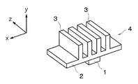
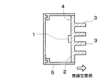
- the heat sink 4 for LED illumination having the above is used for heat radiation such as in-vehicle illumination such as a headlight of an automobile or embedded illumination of a building, as shown in FIG. It will be attached in a state that constitutes the back surface portion of the housing 5 that is the housing of the LED illumination.
- the fin portion 3 is in a closed space where there is no air convection on the back side of the LED lighting. Will protrude.
- heat dissipation from the heat sink is not convectively controlled, and radiation is the center of heat dissipation. Therefore, rather than simply increasing the surface area by providing a plurality of fins on the heat sink, it is better to increase the heat sink's x-axis direction, y-axis direction, and z-axis direction, that is, all three projected areas. It is considered effective for improvement.
- the LED illumination heat sink of the present invention is an LED illumination heat sink formed of an aluminum material, and a mounting surface portion on which an LED element is mounted on the surface, and a direction orthogonal to the mounting surface portion And a second fin portion extending in a direction orthogonal to the mounting surface portion and extending in a direction intersecting the first fin portion.
- the first and second fin portions extend in a direction orthogonal to the mounting surface portion on which the LED element is mounted, and the first fin portion extends in a direction intersecting the second fin portion.
- the projected area in the three-dimensional direction of the x-axis direction, the y-axis direction, and the z-axis direction can all be increased. Therefore, even if it is the heat radiation in the closed space without air convection, the heat radiation can be performed efficiently.
- a flat plate-like first fin portion and / or second fin portion are integrally formed on either or both of the front and back surfaces of the mounting surface portion.
- the number of sheets that are erected outward and are spaced from each other and that extend in the same direction is two or less in any cross section orthogonal to either the front or back surface of the mounting surface portion.
- each of the fin portions is formed at a position sandwiching the LED element in the middle.
- the first and second fin portions are preferably formed in a total of 2 to 8 sheets.
- the shape and structure of the heat sink in particular, the shape and structure of the heat-dissipating fin portion can be achieved without complicating and increasing the number of fin portions.
- this can be achieved by simplifying the shape and structure of the fin portion and reducing the number of fin portions.
- the substrate of the heat sink and the radiating fin are integrally formed, the surfaces of the substrate and the radiating fin are continuous with each other. A path is formed continuously. For this reason, there is no obstacle such as a slit for dividing the heat conduction path, the heat conduction path in the heat sink is not divided, and the heat from the LED element is transmitted to each part constituting the heat sink. Therefore, extremely high heat dissipation of the heat sink is ensured.
- the said mounting surface part and a 1st fin part are formed in the continuous step shape.
- the mounting surface portion, the first fin portion, and the second fin portion are integrally formed by bending an aluminum blank.
- a second fin portion extending in a direction intersecting the first fin portion is further provided at an end portion of the first fin portion.
- the thickness of the mounting surface portion and / or the first fin portion is greater than the thickness of the second fin portion.
- the second fin portions or the second fin portion and the mounting surface portion or / and the first fin portion are overlapped with each other. And it is preferable to thicken partially the thickness in the mounting part of the LED element of the said mounting surface part.
- the heat sink for LED lighting since it is a heat sink having a simple structure formed of an aluminum material, a rolled plate such as a sheet or a coil or a plate processed by extrusion or the like is punched out and cut. It can be manufactured relatively easily by bending the obtained blank, and is lightweight, so it is suitable as a heat sink for LED lighting such as in-vehicle use.
- the LED element is arranged and fixed on the front side of the mounting surface portion, and a plurality of the first fin portions are projected in parallel with a gap on the back side of the mounting surface portion.
- at least one of the first fin portions is the second fin portion bent at a right angle, and the second fin portion is the first fin portion. It is preferable to have a heat radiating surface and a heat radiating surface in a direction orthogonal to the heat radiating surface of the mounting surface portion.
- the heat sink for LED lighting as described above, it can be manufactured by a relatively simple processing method such as cutting and bending from an aluminum material, and the number of components to be configured does not increase.
- the LED element is arranged and fixed on the front side of the mounting surface portion, and a plurality of the first fin portions are projected in parallel with a gap on the back side of the mounting surface portion.
- the mounting surface portion is preferably L-shaped bent in a direction perpendicular to the longitudinal direction of the first fin portion, and the second fin portion is formed by this bending. In this way, it can be manufactured using a relatively simple processing method such as cutting and bending from an aluminum material, and the number of components to be configured does not increase, and there is a narrow space where space is limited, It can also be attached to places with complicated shapes, and a sufficient amount of heat can be ensured from the LED lighting even at places where there is a space limitation.
- the first fin portion protrudes outside the mounting surface portion bent in an L shape, and the bent portion of the first fin portion has a linear cut reaching the outer surface of the mounting surface portion during processing. It is preferable that the first fin portion is divided. In this way, it can be attached to narrow corner corners where space is limited, and there is no such thing as affecting the folding due to the presence of fins when folding the board. Further, since it is not necessary to shorten the projecting dimension of the fin portion, it is possible to further sufficiently secure the heat radiation amount from the LED illumination.
- the first fin portion protrudes inside the mounting surface portion bent in an L shape, and an angle reaching the inner surface of the mounting surface portion during processing is 90 degrees or more in the bent portion of the first fin portion.
- a V-shaped cut is formed and the first fin portion is divided. In this way, it can be attached even in a narrow place with space restrictions, and a sufficient heat radiation area can be secured by the surface area of the substrate part and the fin part, so that the heat radiation from the LED lighting can be further increased. It can be secured sufficiently. It can also be attached to the corner corners of intricate places with space constraints. Furthermore, since there is no influence on the bending due to the presence of the fin portion when the substrate portion is bent, it is not necessary to shorten the projecting dimension of the fin portion. Can be secured.
- the first fin portion and the second fin portion are formed into a corrugated radiating fin shape by corrugation, and a part thereof is crushed to provide a stepped portion. It is preferable that this step portion constitutes the mounting surface portion. In this case, it is preferable that a pre-coating process having an emissivity ⁇ of 0.7 or more is performed on the surface before the corrugating process.
- the heat sink for LED illumination made in this way, a large number of fins with relatively thin intervals can be provided by creating an overall shape of the radiating fins having a continuous waveform by corrugating. Can be increased and heat dissipation can be improved.
- an aluminum alloy thin plate as a raw material, it is possible to pre-treat the raw material aluminum alloy thin plate in advance before corrugating as a process for improving heat dissipation. For this reason, it is possible to omit or shorten the die casting surface buffing, cleaning process, degreasing process, surface treatment process to increase the emissivity of the surface, etc., which were necessary for conventional aluminum alloy die cast casting heat sinks, The manufacturing cost of the heat sink can be greatly reduced.
- the component mounting portion for mounting the LED element and the stepped portion such as the unevenness for reinforcement to improve the rigidity are formed along with the molding of the overall shape of the radiating fin which is a continuous waveform. It can be formed by a series of corrugating processes such as a crushing process that is continuous with the molding process. At this time, it is also possible to design these stepped portions so as to be partially wider than the width of the fin. Therefore, a heat sink in which a large number of fins are provided to ensure heat dissipation while securing the mounting area of the LED element can be integrally manufactured from the same material plate.
- the heat sink for LED lighting of the present invention can increase the projected area in the three-dimensional direction of the x-axis direction, the y-axis direction, and the z-axis direction, so that heat can be dissipated in a closed space without air convection. Even if it exists, the heat dissipation can be performed efficiently.
- FIG. 1 It is a perspective view which shows the heat sink for LED lighting of 2nd Embodiment which concerns on this invention.
- the manufacturing method of the heat sink for LED illumination of 2nd Embodiment is demonstrated, and is a perspective view which shows the form of the plate-shaped aluminum material and blank which consist of coil materials, and the blank after coining process. It is a perspective view explaining the principle and effect
- FIG. 1 It is a perspective view which shows the form of the blank after coining explaining the manufacturing method of the heat sink for LED lighting of the 2nd modification of 2nd Embodiment which has the same 2nd Embodiment and whole shape. It is a perspective view which shows the heat sink for LED illumination of the 3rd modification of 2nd Embodiment in which whole shape differs from 2nd Embodiment.
- the manufacturing method of the heat sink for LED lighting of the 3rd modification of 2nd Embodiment is demonstrated, and it is a perspective view which shows the form of the plate-shaped aluminum material and blank which consist of coil materials, and the blank after coining process. It is a perspective view which shows the heat sink for LED illumination of 3rd Embodiment which concerns on this invention.
- FIG. 16 is a plan view of FIG. 15. It is a sectional side view of the aluminum plate which shows the example when the thickness of the aluminum plate (horizontal plane part) of a LED element mounting part is locally thickened in the heat sink for LED illumination of 3rd Embodiment. It is a perspective view which shows the installation state in the case of applying the heat sink for LED illumination of 3rd Embodiment to the headlight of a motor vehicle.
- FIG. 19 is a cross-sectional view along the line aa in FIG. 18.
- FIG. 19 is a cross-sectional view taken along the line bb of FIG.
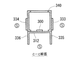
- FIG. 19 is a cross-sectional view taken along the line cc of FIG.
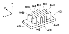
- FIG. 1 It is a perspective view which shows the heat sink for LED lighting of 4th Embodiment which concerns on this invention.
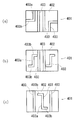
- the heat sink for LED illumination of 4th Embodiment is shown, (a) is a top view, (b) is a front view, (c) is a side view. (A) (b) (c) is a top view which shows the modification of the heat sink for LED illumination of 4th Embodiment.
- It is a longitudinal cross-sectional view which shows the use condition which incorporated the heat sink for LED lighting of 4th Embodiment in LED lighting as a part of housing.
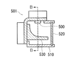
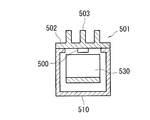
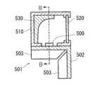
- FIG. 32 is a sectional view taken along line BB in FIG. 31.
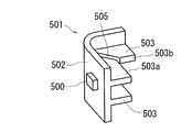
- FIG. 34 is a sectional view taken along line BB in FIG. 33. It is a perspective view which shows the heat sink for LED lighting of 6th Embodiment which concerns on this invention.
- FIG. 36 is a plan view of FIG. 35. It is a perspective view which shows the heat sink for LED lighting of the 1st modification of 6th Embodiment.
- FIG. 38 is a plan view of FIG. 37. It is a perspective view which shows the heat sink for LED lighting of the 2nd modification of 6th Embodiment.
- FIG. 14 shows a heat sink for LED illumination of a fifth modification of the sixth embodiment, where (a) is a perspective view and (b) is a cross-sectional view taken along line X-X ′ of (a). It is a perspective view which shows the heat sink for LED lighting of the 6th modification of 6th Embodiment.
- (A) (b) (c) is a perspective view which shows the heat sink for LED illumination of the 7th modification of 6th Embodiment.
- (A) (b) is explanatory drawing which shows the aspect which attached the heat sink of 6th Embodiment to the vehicle-mounted LED lamp. It is explanatory drawing which shows the outline
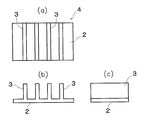
- the conventional heat sink for LED lighting is shown, (a) is a top view, (b) is a front view, (c) is a side view. It is a perspective view which shows the one aspect
- LED element 101 ... LED heat sink 102 ... Substrate (mounting surface) 103, 105 ... Radiating fin (first fin) 104, 106 ... Radiating fin (second fin part) 201 ... Heat sink for LED lighting 211, 212 ... Horizontal flat surface (mounting surface) 221 and 222 ... vertical front part (first fin part) 231 to 236, 2331 to 2334 ... Vertical side surface (second fin) 300 ... LED element 301 ... LED heat sink 311, 312 ... Horizontal flat surface (mounting surface) 321 and 322 ... Vertical front part (first fin part) 331 to 338 ... Vertical side surface (second fin) 400 ... LED light source (LED element) 401 ... Heat sink for LED lighting 402 ...
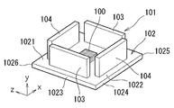
- FIG. 1 shows a heat sink 101 for LED illumination according to the first embodiment.
- This LED lighting heat sink 101 has a plate-like heat radiation fin 103, 104 on either the front or back side of the substrate 102 or both sides 1021, 1022, with respect to the substrate 102 on which the LED element 100 is mounted on either side 1021, 1022.
- the heat dissipating fins 103, 104 are erected outward from either the front or back surface 1021, 1022 of the substrate 102 and are spaced apart from each other.
- the number of fins 103, 104 extending in the same direction is two or less in any cross section perpendicular to the front or back surface 1021, 1022 of the substrate 102.
- the substrate 102 constitutes the mounting surface portion of the present invention
- the radiating fin 103 constitutes the first fin portion of the present invention
- the radiating fin 104 constitutes the second fin portion of the present invention.
- FIG. 1 is a perspective view showing a first embodiment of a heat sink 101 for LED illumination of the present invention
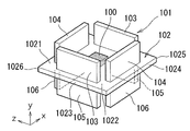
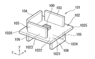
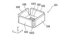
- FIGS. 2 to 7 show a first embodiment of the heat sink 101 for LED illumination of the present invention. Sixth modification examples are shown in perspective views.
- the LED illumination heat sink 101 of the present invention has a flat substrate 102 to which the LED element 100 is attached in common.
- the substrate 102 has two front and rear surfaces 1021 and 1022 on the y-direction (vertical direction) side of each drawing, and these surfaces 1021 and 1022 extend in the x and z directions in each drawing.
- the flat substrate 102 supports the LED element 100 attached to either one of the two front and back surfaces 1021 and 1022.
- FIGS. 1 to 7 the upper surface of each figure is shown for convenience.
- the LED element 100 is attached to the attachment surface 1021 and attached to the center of the plane.
- the other surface on the lower side of each figure is also a back surface 1022 for convenience.
- the heat dissipating side surface may be inclined with respect to the front and back surfaces 1021 and 1022 of the substrate 102 at an angle of less than 90 degrees or greater than 90 degrees, and may be erected outward.
- these flat heat radiation fins 103 to 106 are formed integrally and continuously with the substrate 102 in terms of material. That is, at least the front and back surfaces of the flat plate-like heat radiation fins 103 to 106 are formed continuously with the surfaces 1021 and 1022 of the substrate 102 without interruption.
- the heat from the LED element 100 continues to the back surface 1022, the side surfaces around the radiation fins 103 to 106, and the surface in the plate thickness direction via the surface (front surface) 1021 on the LED element mounting side of the substrate 102.
- a continuous heat transfer surface is formed.
- fever continuously from these continuous heat transfer surfaces is also formed.
- FIGS. 1 to 7 illustrate a rectangular (quadrangle) flat plate shape or planar shape.
- the shape of the substrate 102 may be a three-dimensional shape such as a circular shape, a triangular shape, a polygonal shape, an irregular shape, or a cylindrical shape, a rectangular tube shape, or a step shape, depending on the use of the heat sink 101 for LED lighting.
- a dimensional shape or the like can be selected as appropriate.
- heat dissipation fins The basic structure itself of the heat sink 101 for LED lighting of the present invention described above seems to be not significantly different from the structure of the conventional heat sink 4 illustrated in FIG.
- the flat heat dissipating fins 103 to 106 are arranged in such a way as to mainly radiate heat that is required in the narrow space or closed space of the housing for in-vehicle lighting. to differ greatly.
- flat plate-like heat radiation fins 103 to 106 are preferably provided in total on the two surfaces 1021 and 1022 of the substrate 102, respectively. Up to eight sheets are formed continuously and integrally with the surfaces 1021 and 1022 of the substrate 102 so as to be spaced apart from each other.
- the number of fins extending in the same direction including the parallel state is two in any cross section orthogonal to the two surfaces 1021 and 1022 of the substrate 102. It is assumed that: In other words, the number of the heat sinks 101 is two or less in any cross section cut along a cross section in an arbitrary direction orthogonal to the two surfaces 1021 and 1022 of the substrate 102.
- extending in the same direction as each other includes a parallel state as a matter of course, but it does not mean only parallel in a strict sense, but also a flat plate-like side surface of radiating fins.
- the angle of the extending direction may be slightly different.
- the object of the present invention is to eliminate the excessive overlap of the heat dissipating fins in any of the three-dimensional directions of the heat sink, to obtain a performance with no material waste and high heat radiation efficiency. Therefore, even if the angles of the extending directions of the flat plate side surfaces of the radiating fins are slightly different within a range not hindering the purpose and effect, it can be considered that they extend in the same direction.
- the radiating fins should be regulated in the present invention in the same direction This is because there is no great difference between facing each other and overlapping each other.
- the radiating fins As a measure of the difference in angle, if the angle formed by the extending directions of the flat plate side surfaces of the radiating fins is 30 degrees or less, it is considered that the radiating fins extend in the same direction. On the contrary, if the angle formed by the extending directions of the flat plate-shaped side surfaces of the radiating fins exceeds 30 degrees, the radiating fins are not considered to extend in the same direction.
- two radiating fins are arranged in parallel to each other so as to extend in the same direction with the LED element 100 sandwiched between them, and are arranged in a rectangular shape with the LED element 100 as a center.
- the adjacent radiating fins are arranged orthogonally to each other (crossing at right angles).
- the present invention is not limited to such an arrangement, and surrounds the periphery of the LED element 100 on a circle or arc centered on the LED element 100, for example, in the form of a domino, for example, the angle of the flat plate side surface
- the heat radiating fins may be arranged at intervals while sequentially changing.
- the number of fins extending in the same direction as each other can be expressed as “in any cross section orthogonal to the two surfaces 1021 and 1022 of the substrate 102 (in any cross section of the heat sink cut in this cross section) 2.
- the reason why it is defined as “less than or equal to the number of sheets” is to prevent the fins from excessively overlapping each other in a certain direction in the three-dimensional space. Note that, as will be described later, even a single fin may have a plurality of flat plate-shaped heat radiation surfaces (heat radiation side surfaces) extending in different directions, such as an L shape or a U shape.
- the number of fins extending in the same direction is two or less, so that the heat dissipating fins or the heat dissipating side surfaces of the heat dissipating fins are You can avoid overlapping each other.
- the above-mentioned rule is that the number of heat dissipating surfaces (heat dissipating side surfaces) of the heat dissipating fins is regarded as the number of fins, and the two surfaces 1021 and 1022 of the substrate 102 are positioned. Regardless, excessive overlap is avoided and the two or less sheets are specified.
- the number of fins extending in the same direction is defined as “two or less on any of the surfaces 1021 and 1022 of the substrate 102” as an expression different from the above definition,
- the absolute number of fins will be specified.
- the heat radiation surfaces in different directions of the heat radiation fins such as L-shape or U-shape cannot be regarded as the number of fins, and depending on the positions of the two surfaces 1021 and 1022 of the substrate 102, excessive overlapping occurs. there is a possibility. Therefore, it is defined as “two or less sheets in any cross section orthogonal to the two surfaces 1021 and 1022 of the substrate 102 (in any cross section of the heat sink cut in the cross section in this direction)”.
- FIGS. 1 to 7 exemplify the overall shape and the shape of the flat plate side surface as a rectangle (rectangle).
- the flat shape and three-dimensional shape are not limited to this rectangle.
- the adjacent heat radiation fins 103, 104 or 105, 106 are integrated.
- a U-shape may be used, such that the adjacent radiating fins 103, 104, 103 or 105, 106, 105 are integrated.
- heat dissipation side surfaces flat heat dissipation surfaces
- arc-shaped or curved heat dissipation surfaces heat dissipation side surfaces
- the entire shape you may make it the shape and thickness of the plate
- the heat radiating surface it is possible to appropriately select the heat radiating surface as a surface shape such as a circle, a triangle, a polygon, and an indeterminate shape.
- FIGS. 1 to 7 specific embodiments of the present invention shown in FIGS. 1 to 7 will be described.
- the significance of the number of plate-like radiating fins 103 to 106 and the definition of the arrangement will be described. That is, the significance of the point that the total number of flat radiating fins 103 to 106 is preferably 2 to 8 in total will also be described.
- any of the heat sinks 101 to 106 in which the number of fins extending in the same direction is cut in a cross section in an arbitrary direction orthogonal to any of the surfaces 1021 and 1022 of the substrate 102. The significance of having two or less in the cross section will also be described.
- a total of four plate-like heat dissipating fins 103 and 104 are provided on the side of the LED element mounting surface 1021 that supports the LED element 100 of the substrate 102, and the surface 1021 of the substrate 102 and the plate-like side surfaces thereof are integrated. It is provided continuously. No heat radiation fin is provided on the other back surface 1022 side, and only a flat plate-like back surface 1022 exists.
- the two heat dissipating fins 103, 104 provided on the LED element mounting surface 1021 side are symmetrically arranged with the LED element 100 in between, the heat dissipating fins 103, 103 on the left and right sides of the figure, and
- the upper and lower radiating fins 104, 104 are provided in parallel with each other as an aspect extending in the same direction. That is, flat plate-like heat radiation fins 103 and 103 facing each other, and 104 and 104 are formed on the surface side which is the LED element mounting surface 1021 at a position sandwiching the LED element 100 in the middle.
- the number of fins extending in the same direction is the same in any cross section orthogonal to the surfaces 1021 and 1022 of the substrate 102 (the heat sink 101 cut in the cross section in this direction). (In any cross section), the number is 2.
- the radiation fins 103, 104 are formed so that adjacent radiation fins are orthogonal to each other (crossing at right angles),
- the flat plate-like side surfaces of the heat dissipating fins 103 and 104 which are arranged and surrounded and have a large heat emissivity, are oriented in the x and z directions, respectively.
- the LED element mounting surface 1021 and the other back surface 1022 of the substrate 102 having a large heat emissivity are directed in the y direction.
- each surface 1023, 1024, 1025, 1026 in the plate thickness (thickness) direction around the four sides of the substrate 102 (1023 is the left side of the figure, 1024 is the lower side of the figure, 1025 is the right side of the figure, 1026 is the upper side of the figure ) Is relatively smaller in area than the respective surfaces 1021 and 1022, but is directed to each direction in the x and z directions, and becomes a radiation surface for heat in these directions.
- This is the same for each surface (upper surface, both end surfaces) in the plate thickness (thickness) direction of each radiating fin 103, 104, and is relatively smaller in area than the flat plate side surface, but has a larger number of surfaces.
- the top surface and the both end surfaces face four surfaces in total in the x, y, and z directions, respectively, and serve as heat radiation surfaces in these directions.
- the radiation surfaces overlap each other, but these three dimensions of x, y, and z In any direction, the heat dissipating surfaces of the heat dissipating fins are not excessively overlapped, and there is no waste of material. For this reason, the heat from the LED element 100 described above is continuously transferred to the back surface 1022, the side surfaces around the radiation fins 103 and 104, and the surface in the plate thickness direction via the mounting surface 1021 of the substrate 102.
- High heat radiation efficiency can be obtained by a synergistic effect with the formation of the continuous heat transfer surface and the effect of forming the continuous heat dissipation surface that radiates heat continuously from these continuous heat transfer surfaces.
- Number of radiating fins If the number of radiating fins extending in the same direction is further reduced to provide only two, which is the preferred lower limit, in any cross section orthogonal to the surfaces 1021 and 1022 of the substrate 102, FIG. One or both of the left and right radiating fins 103, 103 and either or both of the radiating fins 104, 104 on the upper and lower sides of the figure are left, and the other radiating fins are removed. In this case, the left and right radiating fins 103, 103 in FIG. 1 may be left, the upper and lower radiating fins 104, 104 in FIG. 1 may be left, and either one of the radiating fins 103, 104 may be left. May be left.
- the number of radiating fins to be provided is 8 or less, preferably 2 to 8 in total, the total number of radiating fins provided on the two front and back surfaces 1021 and 1022 of the substrate 102.
- the same heat radiation fins 103 to 106 are simply divided into some or finely separated and divided in the extending direction of the heat radiation side, the same heat radiation is used. Consider one fin.
- the problem when the total number of the flat plate-like radiating fins is large is that the number of fins extending in the same direction (in parallel) with each other as shown in the comparative example of FIG. 3 or more in any cross section orthogonal to the two surfaces 1021 and 1022 (3 or more in any cross section of the heat sink 101 cut in a cross section in any direction orthogonal to the two front and back surfaces 1021 and 1022 of the substrate 102) If it is too much, it will occur as well.
- the comparative example of FIG. 50 if there are four fins each extending in a direction parallel to each other on both front and back surfaces 1021 and 1022 of the substrate 102, the heat radiation fins arranged in parallel in the conventional example of FIG.
- First modification of the first embodiment of FIG. 2 is not only provided on one side of the LED element mounting surface (front surface) 1021 of the substrate 102 as shown in FIG. 1, but also on the other back surface 1022 side of the substrate 102.
- the provided form is shown.
- the LED element mounting surface 1021 is also provided on the other back surface 1022 side.
- four radiating fins 105 and 106 are provided, two by two, and a total upper limit of eight is provided.
- the radiating fins 105, 106 provided on the back surface 1022 side are exactly the same as the flat plate-shaped radiating fins 103, 104 provided on the LED element mounting surface 1021 side of the substrate 102, and in the vertical direction of the figure. It has a symmetrical arrangement. In other words, two radiating fins 105, 105 on the left and right sides of the figure and the radiating fins 106, 106 on the upper and lower sides of the figure extend in the same direction, symmetrically with the LED element 100 in between. As an aspect to perform, they are provided in parallel with each other.
- the flat plate-like heat radiation fins 105, 105 facing each other, and 106, 106 are the flat plate-shaped heat radiation fins 103, 103 and 104 on the front side which is the LED element mounting surface 1021, Similarly to 104, it is formed in the position which pinches
- the plate-like radiating fins are formed on both the front and back surfaces of the substrate 102 at a position sandwiching the LED element 100 in the middle.
- the number of fins extending in the same direction as each other may be any cross section orthogonal to the surface 1022 of the substrate 102 (any of the heat sinks 101 cut along the cross section in this direction). (Even in the cross section), the number is 2.
- the heat radiating fins 105, 106 are surrounded by the adjacent radiating fins orthogonal to each other (crossing at right angles),
- the flat plate-like side surfaces of the heat radiation fins 105 and 106 having a large heat emissivity are directed in the x direction and the z direction, respectively.
- the LED element mounting surface 1021 and the other back surface 1022 of the substrate 102 having a large heat emissivity are directed in the y direction.
- the plate 102 has four radiating fins 103 and 104 provided on each side 1023, 1024, 1025, and 1026 in the plate thickness direction of the substrate 102 and on the LED element mounting surface 1021 side of the substrate 102. Not only each surface in the thickness direction (upper surface and both end surfaces), but also each surface (lower surface and both end surfaces) in the plate thickness direction of each radiating fin 105, 106 on the back surface 1022 side becomes a heat radiation surface. Each surface in the plate thickness direction of each of these radiating fins is relatively small in area, but the number of surfaces on both the upper and lower surfaces and both end surfaces is twice that in FIG. Each of them faces a total of 8 surfaces, and becomes a radiation surface of heat in these directions.
- the LED element mounting surface 1021 side of the substrate 102 is omitted from the arrangement of the radiation fins of FIG. It is a sheet.
- the other back surface 1022 side also has three asymmetric radiating fins arranged in the vertical direction in the figure, with three of the two radiating fins 105 excluding the left one in the figure, for a total of six radiating heat. Fins are provided.
- the LED element mounting surface 1021 side of the substrate 102 is omitted from the arrangement of the heat dissipating fins in FIG. 2, and the heat dissipating fins 104, 104 on the upper and lower sides in the figure are omitted. Only two radiating fins 103, 103 on the left-hand side are provided.
- the other back surface 1022 side also maintains the symmetrical arrangement of the radiating fins in the vertical direction of the figure, and omits the two radiating fins 106, 106 on the upper and lower sides of the figure, and the left and right radiating fins of the figure. Only two of 105 and 105 are provided, and a total of four radiating fins are provided.
- FIG. 5 differs from the arrangement of the heat radiation fins in FIG. 2 in that the LED element mounting surface 1021 side of the substrate 102 is omitted and the heat radiation fins 104 and 104 on the upper and lower sides in the figure are omitted.
- 4 is the same as FIG. 4 in that only two heat dissipating fins 103, 103 on the right side are used. Then, as the arrangement of the asymmetrical radiating fins in the vertical direction in the figure, the radiating fins 106, 106 on the upper and lower sides in the figure are omitted, with the other back surface 1022 side excluding the two radiating fins 105, 105 on the left and right sides in the figure. These are only two, and a total of four radiating fins are provided.
- the heat sink 101 for LED illumination shown in FIGS. 6 and 7 is formed by integrally forming a substrate 102 (surfaces 1021 and 1022) and flat plate-like heat radiation fins 103 to 105 from a thin metal plate having a certain plate thickness such as aluminum. An embodiment is shown.
- the flat radiating fins 103 to 105 are bent from the end side of the substrate 102 toward the z direction (the vertical direction in the figure), which is the extending direction of each surface, so that the material is integrated. Formed.
- the fins 103, 103, 104, 104 are bent upward in the figure so that they face each other.
- the fins 104 and 104 are bent so as to face each other, and the fins 103 and 103 are bent so as to face each other.
- the arrangement and the number of the plate-like heat radiation fins 103 to 105 are the same as those in FIG. 1 for FIG. 6 and FIG. 7 for FIG. However, since the radiating fins 103 and 104 are formed by bending the end portion of the substrate 102, the arrangement structures located at the end portions of the substrate 102 are different.
- the heat Q conducted to the LED element mounting surface 1021 is not only applied to the radiation fins 103 and 104 on the mounting surface 1021 side, but also to the rear surface 1022 and the radiation fins 105 and 106 on the rear surface 1022 side. It is transmitted (conducted) to each heat-dissipating surface quickly (without delay) and almost equally at a high level. For this reason, the convection of these fins from the heat radiating surface, and in particular, the heat radiated by radiation is equally performed at a certain level or higher, and the heat radiation efficiency can be improved.
- the heat dissipating fins 103 to 106 have two or less fins extending in the same direction in any cross section orthogonal to the surfaces 1021 and 1022 of the substrate 102. And do not overlap too much in the same direction. Therefore, the transmitted heat Q is directed in the three-dimensional directions of x, y, and z, and from the mounting surface 1021 and the back surface 1022 of the substrate 102, the surfaces of the heat radiation surfaces of the heat radiation fins 103 to 106, and the like. Are quickly and efficiently radiated to each closed space (heat radiation space).
- the heat generated by the LED element 100 is dissipated in a three-dimensional x-, y-, and z-direction with a high radiation efficiency of a certain amount or more.
- the heat sink 101 of the present invention has a small heat radiating fins 103 to 106, and in a closed heat radiating space in the lighting fixture where the efficiency of the heat radiation is small and the air convection is small. This is because each projected area in any of the x, y, and z directions is large.
- the heat sink 101 of the present invention has an excellent characteristic that heat dissipation efficiency per unit area of heat dissipation is good while having a simple structure with a small number of heat dissipating fins 103 to 106.
- the heat sink 4 of the conventional example or the comparative example of FIG. 47 has a projected area in the y direction that is the sum of the plane of the substrate portion 2 and the upper plane of the fin portion 3, so that the fin portions 3 overlap each other. Since there is no waste of material, the projected area is large. However, since the projected area in the z direction is the sum of the side surface of the substrate portion 2 and the side surface of the fin portion 3 and has a comb-like shape and a large space, the total of the length of the substrate portion 2 and the height of the fin portion 3 is multiplied. The area is less than 50% of the area.
- the projected area in the x direction is the total of the front surface of the substrate portion 2 and the front surface of the fin portion 3, and even though there are four fin portions 3, for example, they overlap and have the same projected area as one.
- the heat radiation efficiency per heat radiation area is low. That is, in the x direction, a large number of fins occupy the space overlappingly, but the projected area is small and the heat radiation efficiency is low for this high space occupancy.
- the number of fins in the x direction is excessive, and the excessive fins increase the waste of material and increase the weight.
- the heat sink 4 of the conventional example or comparative example of FIG. 47 always has low heat radiation efficiency in any of the x, y, and z axis directions (three-dimensional directions).
- the heat radiation efficiency in any one of the three-dimensional directions cannot be increased, so that the overall heat radiation efficiency is lowered.
- the number of fins is excessive in the above-described x direction and the material is wasted.
- what is common to these prior arts is that in any of the three-dimensional directions of the heat sink, there was no waste of material, and although the space occupancy was low, it could not be a heat sink with high heat radiation efficiency. It is.
- the heat sink of the present invention is optimal in a usage (installation) environment in which the heat dissipation by the air convection is hardly expected in a usage (installation) state where the surrounding heat radiation space is closed and the volume is small and there is almost no air convection.
- the main heat dissipation performance is air convection by increasing the surface area of the heat dissipation surface such as fins. Heat radiation due to this radiation becomes insufficient, and efficient heat radiation cannot be achieved as a whole.
- the heat sink of the present invention is a heat sink that is most suitable for use (installation) environment where heat dissipation by heat radiation from the heat dissipation surface such as the heat dissipation side is mainly used and heat dissipation by air convection can hardly be expected.
- each heat radiation surface including the LED element mounting surface 1021 and the heat radiation fin has an integrated structure without a joint surface therebetween, contact thermal resistance that occurs when both of these manufactured separately are joined. Does not occur. For this reason, the heat conduction between the LED element mounting surface 1021 and each heat radiation surface is easy, and as a result, the heat radiation performance of the entire heat sink is remarkably enhanced.
- the structure of the heat sink 101 is high in rigidity because the heat dissipating fins are oriented in any of the three-dimensional x, y, and z directions. For this reason, even if it is a use which receives a vibration in vehicle-mounted illumination etc., the shape can be maintained without using a special reinforcement member etc., and maintenance-free and lifetime improvement can be achieved.
- the mounting surface 1021 and back surface 1022 of the substrate 102 and the heat dissipating surfaces of the heat dissipating fins 103 to 106 on the heat dissipating surfaces of the substrate 102 such as the space for mounting the component, the slit or the partial shape, etc.
- a part of each surface may be provided by a process of cutting out these surfaces, or a three-dimensional forming process in which unevenness or a step is provided.
- a part of each surface may be omitted or the shape may be changed according to the necessity of component mounting or the like.
- the heat sink 101 of the present invention has an excellent heat dissipation effect, the shape and structure of the heat sink, in particular, the shape and structure of the heat dissipation fins is not complicated, the number of heat dissipation fins is not increased, on the contrary, the structure is simplified, This can be achieved by reducing the number of radiating fins.
- materials and materials include, for example, aluminum (pure aluminum), aluminum alloys, copper (pure copper), copper alloys, steel plates, resins, ceramics, and other raw materials, drawing, bending, and die casting. Or a manufacturing method or manufacturing process such as casting, forging, or extrusion can be selected.
- aluminum (pure aluminum) or an aluminum alloy is preferable as a material having strength, rigidity, weight reduction, corrosion resistance, heat transfer property, heat radiation property, workability, and the like, which are necessary characteristics as the heat sink 101.
- Aluminum (pure aluminum) and aluminum alloys have particularly large heat conduction characteristics and heat dissipation characteristics required for heat sinks, and 1000 series pure aluminum specified in AA to JIS standards is preferable.
- the thickness (thickness) of the substrate 102 and the radiation fins 103 to 106 considers the weight reduction of the heat sink, the required strength and rigidity, and the drawability (formability). Then, it is preferable to select from the range of 0.4 mm to 4 mm. If this plate thickness is too thin, the required strength, rigidity or workability (formability) of the heat sink cannot be ensured. On the other hand, if this plate thickness is too thick, weight reduction of the heat sink is sacrificed.
- the surface emissivity ⁇ of the metal thin plate is preferably 0.6 or more.
- after-coating (paint film) of these paints having high emissivity may be performed.
- This pre-coating process also serves as a lubricant in the drawing process if it is applied to the metal sheet in advance before the drawing process.
- This emissivity ⁇ is a ratio with respect to a theoretical value of thermal radiation of an actual object (thermal radiation of a black body which is an ideal thermal radiator), and actual measurement is disclosed in Japanese Patent Application Laid-Open No. 2002-234460.
- the described method may be used, and measurement may be performed by a commercially available portable emissivity measuring apparatus.
- an in-vehicle LED lamp (vehicle lamp) includes an LED board on which an LED element as a light source is mounted, a reflector that reflects light from the LED forward in the light irradiation direction, and surrounds the LED board and the reflector. And an outer lens made of a transparent material for closing the open front end of the housing, and a heat sink disposed in thermal contact with the LED substrate.
- the reflector is formed of a resin material and includes a parabolic reflecting surface having a focal point near the LED on the LED substrate.
- the heat sink of the present invention is used as the LED substrate or a heat sink disposed in thermal contact with the LED substrate. Even in this case, the heat sink of the present invention as an in-vehicle LED lamp is greatly different from the heat sink of the present invention in that it mainly uses heat radiation instead of heat radiation by air convection that is transferred to the air.
- FIG. 6 corresponding to FIG. 1, FIG. 2, the first modification of FIG. 2, the conventional example of FIG. 47, the heat sink of each shape of the comparative example of FIG. 50 is actually manufactured, the LED element is mounted, current is applied, After making it light-emit, the temperature of the LED element was measured. The results are shown in Table 1.
- the heat sinks of the respective shapes of the first modified example of FIG. 2, the conventional example of FIG. 47, and the comparative example of FIG. 50 were manufactured by machining such as cutting from an extruded rod of JIS 1100 series aluminum material.
- the heat sink of the invention example of FIG. 6 corresponding to FIG. 1 was manufactured by bending the end of a JIS 1100 series aluminum cold-rolled plate into a heat radiating fin by press molding.
- the size of the rectangular shape of the substrate is 100 mm (z direction) ⁇ 100 mm (x direction) ⁇ plate thickness 2 mm
- the rectangular shape of the radiation fin is 70 mm (the length in the z direction of the flat plate side surface) ⁇ 30 mm (the height in the y direction of the flat plate side surface) ⁇ the plate thickness was 2 mm.
- the intervals between the heat dissipating fins parallel to each other, 103 and 103 on the left and right sides, and 104 and 104 on the upper and lower sides of the inventive example were 80 mm or more (the distance from the center of the LED element was 35 mm or more).
- the interval between adjacent heat dissipating fins in the conventional example and the comparative example was 10 mm.
- a commercially available black cationic resin film was electrodeposited on the surface.
- the surface emissivity at this time was 0.85 in common with each example when measured with a commercially available portable emissivity measuring device developed by the Japan Aerospace Exploration Agency.
- Invention Examples 1 and 2 corresponding to the first modification of FIG. 6 and FIG. 2 corresponding to FIG. 1 are the steady state LEDs in a closed space without air convection of the in-vehicle LED lamp.
- the element temperature can be kept at an extremely low temperature of 42 ° C. or less, which is 100 ° C. or less, exemplified by the allowable temperature at which the light emission efficiency of the device does not decrease, and has excellent heat radiation performance (cooling performance) due to heat radiation. It could be confirmed.
- the invention example 2 in FIG. 2 which has the preferred number of fins of 8 as the number of fins, naturally has better heat dissipation performance than the invention example 1 in FIG. It becomes heavier and there is not much difference in terms of heat dissipation efficiency.
- the LED element temperature in the steady state is 100 ° C. or less, but is higher than the invention example. It was confirmed that the heat radiation performance (cooling performance) due to heat radiation was inferior in the closed space where there was no air convection of the LED lamp.
- These series of tests do not take into account the heat input from an engine, heat exchanger, various electric devices, heat input by direct sunlight, etc. that are assumed when mounted in an actual vehicle. For this reason, it is thought that LED element temperature has come out lower than the LED element temperature in actual vehicle-mounted LED (real vehicle mounting LED). However, these series of tests have sufficient accuracy and reproducibility as a performance comparison of heat sinks.
- the heat sink of the present invention is mainly radiated by radiation of heat from the radiating surface such as the radiating side, and has almost no air convection (almost no heat radiated by air convection can be expected). ) Is the best heat sink. For this reason, it can be used for the heat radiating component for vehicle lighting lamps, such as a vehicle-mounted LED lamp.
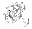
- FIG. 8 shows a heat sink 201 for LED illumination according to the second embodiment.
- This LED lighting heat sink 201 is an LED lighting heat sink 201 made of a plate-like aluminum material, and is formed by integrally bending a blank 241 made of aluminum material,
- the vertical front portions 221 and 222 are composed of stepped substrate portions 202 alternately arranged, and LED element mounting portions 203 are formed on the surface of the horizontal plane portion 211 or / and the vertical front portions 221 and 222 of the substrate portion 202. It is characterized by.
- the horizontal plane portion 211 constitutes the mounting surface portion of the present invention
- the vertical front portions 221 and 222 constitute the first fin portion of the present invention
- the vertical side surface portions 231 to 236 described later constitute the second fin portion of the present invention.
- the heat sink 201 is formed of a plate-like aluminum (including its alloy) material having a constant and equal thickness, and has a stepped shape as a whole. It is configured. That is, in this board part 202, from the upper part of the stairs, the horizontal plane part and the vertical front part that are perpendicular to each other are alternately arranged in the order of the vertical front part 221, the horizontal flat part 211, and the vertical front part 222 having the same rectangular shape.
- the shape (structure) is integrated continuously.
- a swelled LED element mounting portion 203 is provided at the center of the surface of the horizontal plane portion 211 of the substrate portion 202.
- side plate portions 204 that are perpendicular to the substrate portion 202 are integrally provided at both ends of the heat sink 201 on both sides of the substrate portion 202. That is, the vertical front portion 221 at the top of the substrate portion 202 has a vertical side surface portion 231 and a vertical side surface portion 232 that are arranged at right angles to the front surface portion 221 and are continuously arranged toward the rear thereof. Further, at both ends of the horizontal plane portion 211 of the substrate portion 202, a vertical side surface portion 233 and a vertical side surface portion 234 that are arranged at right angles to the horizontal plane portion 211 and continuously downward are provided. Have. Furthermore, the vertical front portion 222 at the bottom of the substrate portion 202 has a vertical side surface portion 235 and a vertical side surface portion 236 that are arranged at right angles to the front surface portion 222 and continuously toward the front thereof on both sides thereof.
- the thickness of the substrate portion 202 and the side plate portion 204 constituting the heat sink 201 is generally 0.5 to 5 mm from the viewpoint of rigidity, heat dissipation and weight reduction, although it depends on the overall size. Is desirable.
- the aluminum material is not particularly limited, but it is desirable to use a JIS 1000 series pure aluminum, a JIS 3000 series aluminum alloy, a JIS 5000 series aluminum alloy having excellent thermal conductivity and formability.
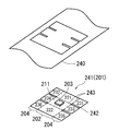
- a plate-shaped aluminum coil material 240 manufactured by rolling is punched, and one sheet corresponding to the planar shape of the developed view corresponding to the three-dimensional shape of the heat sink 201 of FIG.
- a blank 241 is obtained.
- the blank 241 has a rectangular shape as a whole, and has two portions on each side, and four notches 242 in total.
- the notch 242 is located at a position obtained by dividing the length of the blank 241 into three equal parts, and has a strip shape extending in parallel with a predetermined length from the end on the long side of the blank 241 to the center.
- a sheet material manufactured by rolling may be used.
- a rectangular parallelepiped LED element mounting portion 203 bulging upward by coining is formed at the center of the surface of the blank 241.
- each part of the blank 241 is bent.
- Reference numeral 202 denotes a substrate portion
- 204 denotes a side plate portion.
- a broken line portion is a boundary line between successive portions, and indicates a bend line (fold) at the time of bending.
- the 221 surface portion of the blank 241 is bent upward at a right angle around the bending line 243 that is the boundary line with the 231 surface portion and the 232 surface portion, and the 222 surface portion is integrated with the 235 surface portion and the 236 surface portion.
- 8 is bent downward at a right angle around a bend line 243 that is a boundary line with the 211 surface portion, and is formed in a stepped shape comprising an upper vertical front portion 221, an intermediate horizontal plane portion 211, and a lower vertical front portion 222 in FIG.
- the substrate portions 202 that are alternately continuous are formed.
- the 231 plane portion and the 232 plane portion are bent at a right angle rearward (downward in FIG.
- the 233 and 234 surface portions are bent downward at a right angle around a bend line 243 serving as a boundary line between the 211 surface portion and a vertical side surface portion 233 continuous with the two sides of the horizontal plane portion 211 in FIG.
- the vertical side surface part 234 is formed.
- Production of the LED lighting heat sink 201 of the embodiment of FIG. 8 is completed by bending the blank 241 described above.
- the processing order of each part in the bending process of the blank 241 for manufacturing the heat sink 201 of the present embodiment is not particularly limited to the above-described method. Even if the order of processing is appropriately changed, the heat sink 201 can be similarly manufactured.
- the LED lighting heat sink 201 of the embodiment of FIG. 8 can be easily manufactured by simply punching, coining and bending an aluminum plate obtained by plastic processing such as rolling, Moreover, since the structure is a combination of thin plate materials, it is extremely lightweight and has sufficient rigidity. Further, the manufacturing cost can be greatly reduced as compared with the conventional die-cast one.
- the heat generated by the LED element is conducted to the horizontal plane portion 211 through the LED element mounting portion 203.
- the heat conducted to the horizontal plane portion 211 is conducted to the vertical front portions 221 and 222 and the vertical side portions 233 and 234.
- the heat Q conducted to the horizontal plane portion 211 is transferred from the front and back surfaces of the same plane portion to the surrounding closed space (heat radiation space) S in the perpendicular direction (the vertical direction in the figure, the arrow of the heat Q from the back surface is omitted). Radiated.
- the heat Q transmitted to the vertical front portions 221 and 222 is radiated from the front and back surfaces of the flat surface portion to the same space S in the perpendicular direction (the front-rear direction in the figure, the arrow of the heat Q from the back surface of 222 is omitted). Further, the heat Q transmitted to the vertical side surface parts 233 and 234 is radiated from the surface of the side surface part into the same space S in the perpendicular direction (right and left directions in the figure, and arrows of the heat Q from the back surface are omitted).
- a part of the heat Q conducted to the vertical front part 221 is conducted to the vertical side parts 231 and 232, and the surrounding space S in the right-angle direction (right and left directions in the figure) from the front and back surfaces of the both side parts. To be emitted. Further, a part of the heat Q conducted to the vertical front part 222 is conducted to the vertical side parts 235 and 236, and the surrounding space S in the direction perpendicular to the front and back surfaces of the both side parts (right and left in the figure). To be emitted.
- the vertical side surfaces 231 to 236 radiate less heat by radiation than the horizontal flat surface 211 and the vertical front surfaces 221 and 222 because 231 and 232, 233 and 234, and 235 and 236 face each other.
- the heat Q from the surface of the 231 (right side of the figure) and the surface of the 232 (left side of the figure) is radiated directly to the surrounding space S in the perpendicular direction, and is sufficiently dissipated.
- the heat sink of FIG. 8 is composed of the step-like substrate portion 202 in which the horizontal plane portion 211 and the vertical front portions 221 and 222 are alternately arranged, and the vertical side surface portions 231 to 236 are formed at both side ends of the substrate portion 202. Therefore, even in a closed heat-dissipating space in which the heat dissipation efficiency is dominated by radiation and the convection is less likely to occur, the projection area in the x, y, z direction, that is, the three-dimensional direction, is very large, so that the radiation efficiency is high. It can be seen that it has excellent heat dissipation.
- FIG. 8 a first modification of the second embodiment having the same overall shape as that of the second embodiment of FIG. 8 will be described.
- the heat sink itself of the first modified example of the second embodiment is not shown, the stepped substrate portion 202 (horizontal plane portion 211, vertical front portion 221 and vertical front portion 222) of FIG.
- the vertical side surfaces (231, 232, 233, 234, 235, 236) provided at the end portions on both sides differ only in thickness, and other than that, they have exactly the same shape as in FIG. .
- a first modification of the second embodiment will be specifically described based on FIG. 11 showing the form of the blank after coining.
- the blank 241 has a rectangular shape as a whole, has two portions on each side, and four notches 242 in total, and has a thick substrate portion 202 at the center and a thickness on both sides. It is a blank having a different thickness in the width direction composed of thin side plate portions 204. Regarding the manufacturing method of this blank 241, two types of plate-like aluminum coil materials with different thicknesses produced by rolling are prepared, and one thick plate obtained by punching or cutting each of them. Two thin plates are welded together. Reference numeral 244 denotes a weld bead portion. Then, a strip-shaped notch 242 extending in parallel with a predetermined length from the end to the center is formed at a position obtained by dividing the length into three equal parts.
- the heat sink 201 according to the first modification of the second embodiment can be easily manufactured by bending the blank 241 described in the second embodiment.
- the heat sink 201 according to the first modified example of the second embodiment has the same three-dimensional shape as that shown in FIG. 8, but the substrate portion 202 constituting the stepped shape, that is, the vertical front portion 221 and the horizontal plane portion shown in FIG.
- the thickness of 211 and the vertical front part 222 is characterized by being thicker than the thickness of the side plate part 204, that is, the vertical side parts 231, 232, 233, 234, 235 and 236.
- the thickness of the substrate portion 202 is preferably 0.5 to 5 mm
- the thickness of the side plate portion 204 is preferably 0.25 to 2.5 mm.
- the rigidity of the stepped substrate 202 serving as the skeleton of the heat sink can be further increased as compared to the second embodiment shown in FIG.
- the thermal conductivity can be maintained higher, and the heat dissipation can be further improved.
- the blank 241 has a rectangular shape as a whole, and has two notches 242 on both sides, a total of four notches 242, and a thick substrate portion 202 at the center and thick on both sides. It is composed of a thin side plate portion 204, and the shape of the blank is the same as described above. However, the blank 241 is different from the one obtained by welding and integrating plates obtained from two types of plate-like aluminum coil materials having different thicknesses.
- the blank 241 is made of an aluminum extruded material having a thick substrate portion 202 at the center and thin side plates 204 on both sides.
- extrusion may be performed using a mold corresponding to the cross-sectional shape, and then a notch 242 may be provided.
- the heat sink 201 according to the second modification of the second embodiment can be easily manufactured in the same manner.
- the second modified example of the second embodiment can also increase the rigidity of the stepped substrate 202 serving as the skeleton of the heat sink 201 as compared with the second embodiment shown in FIG.
- the thermal conductivity can be maintained higher, and the heat dissipation can be further improved.
- the blank 241 having a uniform and different thickness in the width direction can be manufactured by extrusion without punching or welding, the heat sink manufacturing process is more than that shown in FIG. It will be easy.
- the second embodiment is not limited to this.
- the one shown in FIG. 8 has a single stepped shape composed of three surfaces including upper and lower vertical front portions 221 and 222 and a horizontal plane portion 211 therebetween, but further increases the projected area to the heat radiation space. Therefore, these may be configured to have four or more surfaces and the number of steps may be two or more.
- the horizontal plane part 211 and the vertical front parts 221 and 222 constituting the staircase are all the same rectangle with the same length and width (rectangular shape). Different rectangles may be alternately arranged, that is, the stairs (one step) may have different widths, depths, and heights.
- the staircase may have an irregular shape shifted in the width direction (left and right) by the step.
- the vertical front portion 221, the horizontal flat portion 211, and the vertical front portion 222 are provided with vertical side portions 231, 232, 233, 234, and 235, 236, respectively. Of these, all or one of the side surfaces 231, 232, 235, and 236 at both ends of the side surfaces 221 and 222 may be omitted.
- the LED illumination heat sink of the third modification of the second embodiment is formed of a plate-like aluminum (including its alloy) material having a constant and equal wall thickness as in the second embodiment of FIG.
- the substrate portion 202 has a stepped shape as a whole. 8 is different from the embodiment of FIG. 8 in that the substrate portion 202 further includes a horizontal plane portion 212 that is continuously arranged at the upper part of the vertical front portion 221 at a right angle to the rear portion. It has a two-step staircase shape.
- the structure of the side plate portions 204 provided at the end portions on both sides of the substrate portion 202 is greatly different from that in FIG.
- At the ends on both sides of the horizontal plane portion 212 there are vertical side surface portions 231 and 232 that are arranged at right angles to the lower end and continuously to the lowermost end (the lower end position of the vertical front portion 222).
- the vertical side surfaces are arranged continuously at the ends on both sides of the vertical front portion 221 at a right angle to the front of the vertical front portion 221 until the middle of the entire width of the horizontal flat portion 211 (width of the third).
- the horizontal flat surface portion 211 has vertical side surface portions 2333 and 2334 that are arranged at right angles to the lower end portions of the horizontal flat surface portion 211 and continuously downward.
- the vertical side surfaces 231 and 232 are superposed so as to protrude forward at the respective upper and lower positions and circumscribe part of the surface (rear side) of the vertical side surfaces 2331 and 2332, 2333 and 2334.
- Flange portions 251 and 252 are provided.
- the vertical side surface portions 2333 and 2334 are also provided with overlapping flange portions 253 that project forward at the positions of the respective central portions and circumscribe and partially cover the surfaces (rear side) of the vertical side surface portions 235 and 236. .
- a method for producing the heat sink 201 of the third modification of the second embodiment will be described below with reference to FIG.
- a plate-shaped aluminum coil material 240 manufactured by rolling is punched, and one sheet corresponding to the planar shape of the developed view matched to the three-dimensional shape of the heat sink 201 of FIG.
- a blank 241 is obtained.
- the blank 241 has a T-shape as a whole, and a total of six notches 2421 to 2423 are provided around the blank.
- one notch portion 2421 is provided at both lower portions of the head portion 241a (both sides in front of the drawing), and two notch portions 2422 and 2423 are provided at both side portions of the trunk portion 241b.
- the notch portion 2421 has a two-stage key shape
- the notch portion 2422 has a strip shape
- the notch portion 2423 has a one-step key shape.
- a rectangular parallelepiped LED element mounting portion 203 bulging upward by coining is formed at the center of the surface of the blank 241.
- each part of the blank 241 is bent.
- Reference numeral 202 denotes a substrate portion
- 204 denotes a side plate portion.
- a broken line portion is a boundary line between successive portions, and indicates a bend line (fold) at the time of bending.
- the 221 surface portion of the blank 241 is bent upward at a right angle around the bending line 243 that is a boundary line with the 211 surface portion integrally with the 2331 surface portion, 2332 surface portion, 212 surface portion, 231 surface portion, and 232 surface portion.
- the 222 surface portion is bent downward at a right angle around the bend line 243 that is a boundary line with the 235 surface portion and the 236 surface portion and the 211 surface portion.
- the 212 surface portion is bent at a right angle rearward (downward in FIG. 14) around the bend line 243 integrally formed with the 231 surface portion and the 232 surface portion as a boundary line with the 221 surface portion.
- the substrate portions 202 alternately formed in the order of steps in the order of the horizontal plane portion 212, the vertical front portion 221, the horizontal plane portion 211, and the vertical front portion 222 from the upper part of FIG.
- the 235 plane and 236 plane are bent at a right angle forward (upward in FIG. 14) around the bend line 243 that is the boundary between the 221 plane and the vertical front of FIG.
- a vertical side surface portion 235 and a vertical side surface portion 236 that are continuous with the both end portions of the portion 222 are formed.
- the vertical side surface portion 2333 and the vertical side surface portion 2333 continuous with the two sides of the horizontal flat surface portion 211 in FIG. 13 are formed by bending the 2333 surface portion and the 2334 surface portion downwardly at a right angle around the bend line 243 serving as a boundary line with the 211 surface portion.
- the vertical side surface portion 2334 is formed.
- the overlapping flange portions 253 of the 2333 surface portion and the 2334 surface portion overlap and join the surfaces of the 235 surface portion and the 236 surface portion, respectively. That is, as shown in FIG. 13, the overlapping flange portion 253 of the vertical side surface portion 2333 and the vertical side surface portion 2334 covers and joins part of the vertical side surface portion 235 and the vertical side surface portion 236 (rear side), and this portion has a double structure. become.
- the 2331 surface portion and the 2332 surface portion are bent at a right angle forward (upward in FIG. 14) around the bend line 243 that is a boundary line with the 221 surface portion, and the two sides of the vertical front portion 221 in FIG.
- a continuous vertical side surface portion 2331 and a vertical side surface portion 2332 are formed.
- the vertical side surface portion 231 that is continuously bent at both end portions of the horizontal plane portion 212 in FIG. 13 by bending the 231 surface portion and the 232 surface portion downward at a right angle around the bend line 243 serving as a boundary line between the 212 surface portion and the 231 surface portion. And the vertical side surface portion 232 is formed.
- the overlapping flange portions 251 of the 231 surface portion and the 232 surface portion are overlapped in contact with the surfaces of the 2331 surface portion and the 2332 surface portion, respectively, and the overlapping flange portions 252 of the 231 surface portion and the 232 surface portion are respectively 2333 surface portions and 2334 surfaces.
- Overlapping in contact with the surface of the surface portion that is, as shown in FIG. 13, the overlapping flange portion 251 at the upper part of the vertical side surface portion 231 and the vertical side surface portion 232 is overlapped so as to cover a part (rear side) of the vertical side surface portion 2331 and the vertical side surface portion 2332.
- 231 and the overlapping flange portion 252 below the vertical side surface portion 232 are overlapped so as to cover a part (rear side) of the vertical side surface portion 2333 and the vertical side surface portion 2334, both of which have a double structure.
- the above-described bending process of the blank 241 completes the production of the heat sink 201 for LED illumination of the third modification of the second embodiment in FIG.
- the processing order of each part in the bending process of the blank 241 for manufacturing the heat sink 201 is not particularly limited to the above-described method as in the second embodiment of FIG.
- the third modification of the second embodiment is more complicated than that of FIG. 8
- the folding of the vertical side surface portion having the overlapping flange portion is joined so that the respective portions do not interfere with each other at the time of folding. It is necessary to pay attention so that the processing order is fixed, for example, after the vertical side surface portion on the other side is processed.
- a horizontal plane portion 212, vertical side portions 231 and 232, vertical side portions 2331 and 2332 and the like are added.
- the vertical flanges 251 to 253 are formed on the vertical side surfaces 231 and 232, 2333 and 2334, respectively, and the other vertical side surfaces 2331 and 2332, 2333 and 2334, 235 and 236 are overlapped and joined and connected.
- the heat generated from the LED element is radiated through heat conduction immediately to the end of each vertical side surface (fin) away from the LED element, thereby exhibiting higher heat dissipation.
- the rigidity of the heat sink increases compared to the single sheet structure of FIG. 8, and its strength, durability and stability are improved. Can be achieved.
- the third modification of the second embodiment is an example in which the vertical side surface portions are overlapped with each other via the overlapping flange portion, but the present invention is not limited to this, and the horizontal side surface portion of the vertical side surface portion and the substrate portion 202 is not limited thereto.
- a structure in which the vertical front portions are superposed may be used.
- the double structure portion of the vertical side surfaces in the third modification of the second embodiment is formed by combining the double materials together by a joining method such as screw fastening, rivet fastening, caulking fastening, welding, brazing, or the like. They may be combined, which can greatly increase the rigidity of the heat sink.
- FIG. 15 shows a heat sink 301 for LED illumination according to the third embodiment.
- This LED lighting heat sink 301 is an LED lighting heat sink 301 formed of an aluminum plate 302, and has horizontal step portions 311 and 312 and vertical front portions 321 and 322 that are alternately continuous, and has a horizontal plane.
- LED element 300 is attached to the surface of the front part or / and the vertical front part.
- the horizontal plane portion 312 constitutes the mounting surface portion of the present invention
- the vertical front portions 321 and 322 constitute the first fin portion of the present invention
- the vertical side surface portions 331 to 338 described later constitute the second fin portion of the present invention.
- the heat sink 301 of the third embodiment is formed of an aluminum (including its alloy) plate 302 having a constant thickness, and has an overall stepped shape. Yes. That is, in the case of the figure, it is a two-step staircase, and the entire basic shape formed from the aluminum plate 302 has a staircase shape. That is, in the case of the figure, it has a two-step staircase shape, and the horizontal plane part 311, the vertical front part 321, the horizontal plane part 312, and the vertical front part 322 are perpendicular to each other in this order from the top of the staircase. The horizontal plane portion and the vertical front portion thus formed are alternately and continuously formed (structure).
- These horizontal plane portions 311 and 312 and the vertical front portions 321 and 322 all have the same length as the width of the aluminum plate 302 forming a step shape as the long side, and the length of the aluminum plate is divided into four equal parts. It is a rectangle with a short width.
- Reference numeral 300 denotes an LED element attached to the central portion of the horizontal plane portion 312.
- both side ends of the horizontal plane portion 312 and the vertical front portion 321 are further provided with vertical side surface portions 331 and 332 arranged at right angles to them, that is, vertically.
- the vertical side surface portions 331 and 332 are squares having the widths of the horizontal flat surface portions 311 and 312 and the vertical front surface portions 321 and 322 as one side.
- the principle and action of heat radiation when LED lighting is performed by installing the heat sink 301 having such a stepped shape in a space without air convection will be described.
- the heat generated by the LED element 300 is conducted to the horizontal plane portion 312 through the mounting portion of the LED element 300.
- the heat conducted to the horizontal plane portion 312 is conducted to the vertical front portion 321, the vertical front portion 322, and the vertical side portions 331 and 332.
- the heat conducted to the horizontal plane portion 312 is conducted to two or more vertical front portions or vertical side portions continuous to the horizontal plane portion 312.
- the heat Q transmitted to the horizontal plane portion 312 is radiated from the entire front and back surfaces of the plane portion to the surrounding closed space (heat radiation space) S in the perpendicular direction (vertical direction in FIG. 15) and transmitted to the vertical front portion 321.
- the radiated heat Q is radiated from the entire front and back surfaces of the same plane portion to the same space S in the perpendicular direction (left and right direction in FIG. 15), and the heat Q transferred to the vertical side surfaces 331 and 332 It is radiated to the same space S in the perpendicular direction (right and left directions in FIG. 16). Heat is dissipated from the side of the vertical side surface portion 331 facing the LED element 300 (left surface in FIG.
- a part of the heat Q conducted to the vertical front part 321 is conducted to the horizontal plane part 311, and the same surrounding space in the perpendicular direction (upward and downward in FIG. 15) from the entire front and back surfaces of the plane part) S To be emitted.
- the heat transferred to 312, 321, 322, 311, 331 and 332 is conducted from the higher heat level to the lower heat level.
- the heat sink having a stepped shape as shown in FIG. 15 and further including the vertical side surfaces on both sides of the horizontal plane portion and the vertical front portion constituting the stepped shape is controlled by radiation.
- the projected area in the x, y, z direction that is, the three-dimensional direction, is very large, so that the radiation efficiency is high and the heat radiation is excellent.
- the projected area of the heat sink does not overlap in the radiation direction to the heat radiation space, the heat radiation efficiency per unit heat radiation area is good and a simple structure can be achieved.
- a manufacturing method of the heat sink having the shape shown in FIG. 15 will be described.
- a pure aluminum plate or an aluminum alloy plate (these are simply referred to as an aluminum plate in the present invention) having a predetermined thickness is manufactured by processing such as rolling using pure aluminum or an aluminum alloy as a raw material.
- the aluminum plate to be manufactured has a length L that is four times the size of the short side of the rectangle 311 in FIG. 15 (312, 321 and 322 are the same), and its width W is the length of the long side of the rectangle. 331 (same for 332) is the dimension of one side of the square.
- the length corresponding to one side of the square 331 in FIG. 15 (same for 332) is cut and removed.
- three rectangles having a short width (long side) corresponding to 311, 321 and 322 in FIG. 15 and a width (total width) obtained by adding one side of 331 and 332 to the width of 312 are long.
- An aluminum plate 302 made of one rectangle is obtained.
- the rectangular portion of the horizontal plane portion 311 of the aluminum plate 302 with a short width is bent at a right angle with respect to the rectangular portion of the vertical front portion 321 and the rectangular portion of the horizontal plane portion 312 is bent at the vertical front portion 321.
- the rectangular part of the vertical front part 322 is bounded to the rectangular part of the horizontal plane part 312 which is bent at a right angle to the opposite side of the horizontal flat part 311 with the boundary line as the center. Fold it at a right angle around the line. Thereby, the staircase shape which is a basic shape is completed.
- the square portions of the vertical side surface portion 331 and the vertical side surface portion 332 located on both sides in the width direction of the long horizontal plane portion 312 + the vertical side surface portion 331 + the vertical side surface portion 332 are replaced with the rectangular portion of the horizontal plane portion 312. Are bent at right angles to the surface of the vertical front portion 321 around the boundary line with the horizontal plane portion 312.
- the heat sink 301 of the present invention shown in FIG. 15 can be easily manufactured by using a relatively simple processing means such as cutting and bending using the aluminum plate 302 as a material.
- the method of manufacturing the aluminum plate 302 has been described by taking rolling, but is not limited to this, and other processing methods such as extrusion may be used.
- FIG. 15 is an embodiment showing a basic overall shape, and the third embodiment is not limited to this.
- the number of steps may be three or more in order to further increase the projected area onto the heat radiation space.
- the horizontal plane portions 311 and 312 and the vertical front portions 321 and 322 constituting the two-step staircase are all the same length and the same rectangle, but the length and width are changed.
- different rectangles may be alternately arranged, that is, the stairs (one step) may have different widths, depths, and heights.
- the staircase may have an irregular shape shifted in the width direction (left and right) by the step.
- the horizontal plane portion 312 and the vertical front portion 321 are provided with the vertical side portions 331 and 332 on both sides, but the vertical side portions need to be on both sides of the stepped shape. It is not limited to one side or both sides of the horizontal plane part 312 and the vertical front part 321, and is not limited to one side or both sides of the horizontal plane part 312 and the vertical front part 321 or one side of the horizontal plane part 312 and the vertical front part 321 or It may be provided on both sides. Further, the vertical side surface portion may be arranged vertically on both side (or one side) ends of only one of the horizontal plane portion and the vertical front portion, that is, for example, the horizontal plane portion 311 of FIG.
- the vertical side surface portions 331 and 332 in FIG. 15 are obtained by bending a rectangular aluminum plate made up of the horizontal plane portion 312 + the vertical side surface portion 331 + the vertical side surface portion 332 at a right angle in the same direction. This is preferable because it can be easily formed by cutting and bending the plate material, but separate vertical side surface parts 331 and 332 are prepared in advance, and the vertical body constituting the stepped main body is prepared. They may be formed by welding in a state where they are arranged vertically at both ends of the front portion 321.
- FIG. 17 shows this example and is a side sectional view of the mounting portion of the LED element 300 in the horizontal plane portion 312.
- the thickness of the horizontal flat surface portion 312 excluding the mounting portion of the LED element 300 is the same as the other surface portions 321, 312 and 322, but the back surface side of the horizontal flat surface portion 312 bulges downward in this mounting portion.
- a thick part 3121 is formed.
- FIGS. 18 is a perspective view showing a state where the headlight is installed
- FIG. 19 is a sectional view taken along the line aa in FIG. 18
- FIG. 20 is a sectional view taken along the line bb
- FIG. 21 is a sectional view taken along the line cc.
- the heat sink 301 is formed of an aluminum plate 302 and has a stepped shape (two steps) configured in the order of a vertical front portion 321, a horizontal plane portion 311, a vertical front portion 322, and a horizontal plane portion 312 from the top.
- Vertical side surface portions 331, 332, 333, and 334 are provided at both end portions of the horizontal flat surface portion 311 and the vertical front surface portion 322, and at both end portions of the horizontal flat surface portion 312 and the vertical front surface portion 322, respectively.
- the both sides of the horizontal plane portion 312 have vertical side surfaces 335 and 336 that extend downward (project), and also extend to the sides of the vertical front portion 321 to the rear ( Projecting) vertical side portions 337, 338.
- the vertical side surface portions 331 and 332 are formed by bending portions extending to both sides of the horizontal flat surface portion 311 downward at a right angle and are flush with the side surface of the housing 340.
- the vertical side surface portion 333 is the vertical front surface portion 322.
- the portion extended to both sides is bent forward and at a right angle, and is placed on the outside of the side surface of the housing 340.
- the vertical side surfaces 335 and 336 are formed by bending the horizontal plane portion 312 extending to both sides downward and at a right angle, and the vertical side surfaces 337 and 338 are formed by extending the vertical front surface portion 321 to both sides rearward. It is bent at a right angle.
- Reference numeral 300 denotes an LED element serving as a light emitting source mounted on the upper surfaces of the upper and lower horizontal flat portions 311 and 312.
- Reference numeral 350 denotes a reflector (not shown in FIG. 18) provided on the inner surface side of the upper and lower vertical front portions 321 and 322.
- 360 is an outer lens.
- the heat sink 301 has a frame-shaped housing 340 whose both side surfaces have a substantially arc shape at the upper end and a step shape at the lower end and have a curved opening corresponding to the substantially arc shape at the front.
- the housing is built in a state of being mounted on a stepped heat sink.
- the vertical side surfaces 335, 336 and 337, 338 of the heat sink integrated with the housing 340 are fixed and supported by attachment parts (not shown) of the vehicle body, respectively.
- An outer lens 360 made of transmissive glass having the same shape is fitted into the curved opening of the housing 340.
- the outer surfaces of the vertical front part 321, the horizontal plane part 311, the vertical front part 322, and the horizontal plane part 312 of the heat sink 301 are opposed to the closed space S inside the vehicle body. Further, the inner and outer surfaces of the vertical side surface portions 331, 332, 335, 336 and 337, 338 of the heat sink also face the space S.
- the heat generated along with the light emission of the LED element 300 is caused by the surface portions 311, 312, 321, 322 constituting the stepped shape.
- the heat is radiated by radiation toward the surrounding closed space (heat radiation space) S facing from the inner and outer surfaces of the outer side surfaces and the vertical side surface portions 331 to 338 at both ends thereof.
- this heat radiation is performed by a heat radiation heat sink having a heat radiation surface having a very large projected area in the three-dimensional directions of the x, y and z axes. , It will be very effective.
- FIG. 22 shows a heat sink 401 for LED illumination of the fourth embodiment.
- the LED illumination heat sink 401 is an LED illumination heat sink formed of an aluminum extruded material, and the substrate 402 on which the LED light source 400 is arranged and fixed on the front side is spaced from the back side of the substrate 402.
- a fin part bent piece composed of a plurality of projecting fin parts 403 arranged in parallel, and at least a part of at least one fin part 403 of each fin part 403 is bent at a right angle from the fin part main body 403a.
- the fin part bent piece 403b has a heat dissipating surface in a direction orthogonal to the heat dissipating surface of the fin main body 403a and the heat dissipating surface of the substrate part.
- the substrate portion 402 constitutes the mounting surface portion of the present invention
- the fin portion 403 and the fin portion main body 403a constitute the first fin portion of the present invention
- the fin portion bent piece 403b constitutes the second fin portion of the present invention.
- the LED illumination heat sink 401 (hereinafter sometimes simply referred to as the heat sink 401) of the fourth embodiment is excellent in thermal conductivity and formability of JIS 1000 series pure aluminum, JIS 6000 series aluminum alloy, and the like.
- the heat sink 401 includes, for example, a substrate portion 402 in which the LED light source 400 is disposed and fixed on the front side (shown below in FIG. 22), and the back side of the substrate portion 402. It is comprised from the several fin part 403 arrange
- the fin portions 403 at least one of the fin portions 403 is a fin portion bent piece 403b that is bent at a right angle from the fin portion main body 403a.
- the LED light source 400 is, for example, a plurality of light emitting diode (LED) elements mounted on a substrate based on an aluminum alloy.
- LED light emitting diode
- the fin part bent piece 403b has a heat dissipating surface in a direction orthogonal to the heat dissipating surface of the fin main body 403a and the heat dissipating surface of the substrate unit 402, respectively. That is, the heat radiating surface of the substrate portion 402, the heat radiating surface of the fin portion main body 403a, and the heat radiating surface of the fin portion bent piece 403b are directed to different directions orthogonal to each other (y-axis direction, x-axis direction, z-axis direction). It has become.
- FIG. 23 is a plan view, a front view, and a side view of the heat sink 401 of the fourth embodiment
- FIG. 49 is a plan view, a front view, and a side view of the conventional heat sink 4, respectively.
- a sufficient projected area can be secured in both the plan view, the front view, and the side view, but in the heat sink 4 shown in FIG. 49, only the front view is sufficient. It can be seen that the projected area is not secured.
- four fin portions 403 protrude in parallel to the back side of the substrate portion 402 with a gap therebetween, and two fin portions on both sides of the four fin portions 403. Both end portions of 403 are bent at right angles from the fin portion main body 403a toward both side edges of the substrate portion 402 to form fin portion bent pieces 403b.
- the number and shape of the fin portions 403 need not be the same as those in the embodiment shown in FIG.
- the number of fin portions 403 may be plural, that is, at least two fin portions 403.
- the fin portions 403 on which the fin portion bent pieces 403b are formed are not necessarily on both sides.
- the fin part bent piece 403 b may be formed in the central fin part 403 as shown in FIG.
- FIG. 24 illustrates modified examples of the heat sink 401 having various shapes.
- the heat sink 401 for LED lighting according to the present invention is an aluminum extrusion extruded by using a metal material having excellent thermal conductivity and formability such as JIS 1000 series pure aluminum and JIS 6000 series aluminum alloy. Manufactured based on materials.
- the heat sink 401 shown in FIG. 22 when the heat sink 401 shown in FIG. 22 is manufactured, first, an aluminum extruded material manufactured by extrusion molding (the same shape as the conventional LED lighting heat sink shown in FIG. 47) is prepared, and both sides of the aluminum extruded material are prepared. Notches of appropriate depth are made from both sides of the lower edges of both ends of the fin portion 403 (sites in contact with the substrate portion 402), that is, the lower edges of the fin portions 403 on both sides in total. Next, the fin part bent piece 403b is formed by bending the part where the lower edge of the fin part 403 is cut at right angles toward both side edge directions (outward direction) of the substrate part 402, respectively. The intermediate portion where the lower edge is not cut and not bent becomes the fin portion main body 403a.
- the LED lighting heat sink 401 described above is used as a heat sink 401 for an in-vehicle illumination such as an automobile headlight or an embedded lighting of a building.
- FIGS. 25 and 26 show the LED illumination heat sink 401 for an automobile headlight. The usage state used is shown.
- the heat sink 401 is attached in a state in which the substrate portion 402 constitutes the rear portion of the housing 410 that is the housing of the LED lighting, that is, a part of the housing 410. It will be.
- the fin portion 403 protrudes into a closed space where there is no air convection on the back side of the LED illumination.
- 420 is a translucent outer lens attached to the front of the LED illumination.
- the LED heat sink 401 for LED lighting when used in a state where the fin portion 403 of the heat sink 401 protrudes into the closed space, the heat generated when the LED light source 400 emits light is closed from the heat sink 401.
- the heat is radiated into a space where there is no air convection.
- the LED heat sink 401 according to the present invention can ensure a sufficient projected area in each of the x-axis direction, the y-axis direction, and the z-axis direction. Therefore, even if it is the heat radiation in the closed space, the heat is efficiently radiated.
- FIG. 27 shows a heat sink 501 for LED illumination of the fifth embodiment.
- the LED illumination heat sink 501 is an LED illumination heat sink 501 formed of an aluminum extruded material
- the substrate portion 502 on which the LED light source 500 is arranged and fixed on the front side is spaced from the back side of the substrate portion 502.
- the board portion 502 is formed in an L shape that is bent in a direction orthogonal to the longitudinal direction of the fin portion 503.
- the substrate portion 502 constitutes the mounting surface portion of the present invention
- the side 503a extending in one direction of the fin portion 503 constitutes the first fin portion of the present invention
- the side 503b extending in the other direction of the fin portion 503 is in accordance with the present invention. 2nd fin part is comprised.
- the LED illumination heat sink 501 (hereinafter also simply referred to as the heat sink 501) of the fifth embodiment is excellent in thermal conductivity and formability of JIS 1000 series pure aluminum, JIS 6000 series aluminum alloy and the like.
- the heat sink 501 of the fifth embodiment includes a substrate unit 502 in which the LED light source 500 is disposed and fixed on the front side (the surface on the right corner portion side in FIG. 27), and the substrate unit 502. It is comprised from the several fin part 503 arrange
- the substrate portion 502 is a so-called L-shaped plate that is bent in a direction perpendicular to the longitudinal direction of the fin portions 503 arranged in parallel.
- a first fin portion 503a extending in a direction orthogonal to the substrate portion 502 and a first fin portion 503a extending in a direction orthogonal to the substrate portion 502 and extending in a direction intersecting the first fin portion 503a.
- a fin portion 503 having two fin portions 503b is formed.
- the fin portion 503 is bent outward together with the substrate portion 502, but the bent portion of the fin portion 503 may be stretched to affect the bending processing of the substrate portion 502. It is necessary to shorten the protruding dimension of the fin portion 503 so as not to hinder.
- the LED light source 500 is, for example, a plurality of light emitting diode (LED) elements mounted on a substrate based on an aluminum alloy.
- LED light emitting diode
- FIG. 28 shows a first modification of the heat sink 501 of the fifth embodiment.
- the heat sink 501 also has a substrate portion 502 in which the LED light source 500 is disposed and fixed on the front side (the surface on the right corner corner side in FIG. 28), and the back surface of the substrate portion 502. It is comprised from the several fin part 503 arrange
- the substrate portion 502 is a so-called L-shaped plate that is bent in a direction perpendicular to the longitudinal direction of the fin portions 503 arranged in parallel.
- the fin portion 503 is bent inward together with the substrate portion 502, but the bent portion of the fin portion 503 may be compressed to affect the bending processing of the substrate portion 502. It is necessary to shorten the projecting dimension of the fin portion 503 so as not to hinder the operation.
- FIG. 29 shows a second modification of the heat sink 501 of the fifth embodiment.
- the heat sink 501 also has a substrate portion 502 on which the LED light source 500 is arranged and fixed on the front side (the surface on the right corner portion side in FIG. 29), and the back surface of the substrate portion 502 It is comprised from the several fin part 503 arrange
- the substrate portion 502 is a so-called L-shaped plate that is bent in a direction perpendicular to the longitudinal direction of the fin portions 503 arranged in parallel.
- the fin portion 503 is bent outward together with the substrate portion 502.
- the fin portion 503 is bent before the substrate portion 502 is bent.
- the part is provided with a linear notch 504 reaching the outer surface of the substrate part 502. Since the board portion 502 is bent after the notches 504 are formed in the fin portion 503 as described above, it is not necessary to shorten the protruding dimension of the fin portion 503 as in the embodiment shown in FIG. The heat can be radiated more efficiently than in the embodiment shown in FIG. Further, the fin portion 503 is partitioned into one first fin portion 503a and the other second fin portion 503b by the notch 504.
- FIG. 30 shows a third modification of the heat sink 501 of the fifth embodiment.
- the heat sink 501 also has a substrate portion 502 on which the LED light source 500 is arranged and fixed on the front side (the surface on the left corner corner side in FIG. 30), and the back surface of the substrate portion 502 It is comprised from the several fin part 503 arrange
- the substrate portion 502 is a so-called L-shaped plate that is bent in a direction perpendicular to the longitudinal direction of the fin portions 503 arranged in parallel.
- the fin portion 503 is bent inward together with the substrate portion 502.
- the fin portion 503 is bent as it is before it is bent.
- the part is provided with a V-shaped cut 505 having an angle of 90 degrees or more reaching the outer surface of the substrate part 502. Since the board portion 502 is bent after the V-shaped cut 505 is formed in the fin portion 503 as described above, it is necessary to particularly shorten the protruding dimension of the fin portion 503 as in the embodiment shown in FIG.
- the heat radiation from the LED illumination can be performed more efficiently as compared with the embodiment shown in FIG.
- the fin portion 503 is divided into one first fin portion 503a and the other second fin portion 503b by a cut 505.
- the heat sink 501 for LED illumination described above is used as a heat sink 501 for in-vehicle illumination such as a headlight of an automobile or a built-in illumination of a building.
- FIGS. 31 and 32 show the heat sink 501 of the embodiment shown in FIG.
- FIG. 33 and FIG. 34 show the state of use in which the heat sink 501 of the embodiment shown in FIG. 30 is used as the LED head heat sink 501 of the headlight of an automobile. Are shown respectively.
- the heat sink 501 shown in FIG. 27 is the same as the heat sink 501 shown in FIG. 29, and the heat sink 501 shown in FIG. 28 is the same as the heat sink 501 shown in FIG.
- the heat sink 501 shown in FIG. 29 has an L-shaped substrate portion 502 that is part of a housing 510 that is a housing for LED lighting. It will be attached to the corner. In this way, even in a narrow place where there is a space restriction where the heat sink 4 having the conventional flat substrate portion 2 as shown in FIG. 47 cannot be attached, the L-shape as shown in FIG. If the heat sink 501 having the substrate portion 502 is used (the same applies to the heat sink 501 shown in FIG. 27), it can be attached.
- 520 is a translucent outer lens attached to the front of the LED illumination
- 530 is a reflector that reflects light emitted from the LED light source 500 toward the outer lens 520.
- the heat sink 501 shown in FIG. 30 is attached in such a state that one piece of the L-shaped substrate portion 502 constitutes a part of a housing 510 that is a housing for LED lighting. It will be. In this way, even in a narrow place where there is a space restriction where the heat sink 4 having the conventional flat substrate portion 2 as shown in FIG. 47 cannot be attached, the L-shape as shown in FIG. If the heat sink 501 having the substrate portion 502 is used (the same applies to the heat sink 501 shown in FIG. 28), it can be attached.
- the heat sink 501 shown in FIGS. 28 and 30 can be attached to a corner portion having an intricate shape with space constraints.
- FIG. 35 shows a heat sink 601 for LED illumination according to the sixth embodiment.
- the LED illumination heat sink 601 is characterized in that an aluminum alloy thin plate is formed into corrugated 602 and 603 radiating fin shapes by corrugation.
- the second feature is that a pre-coating process having an emissivity ⁇ of 0.7 or more is performed in advance on the surface of the aluminum alloy thin plate before corrugating.
- a third feature is that the waveforms 602 and 603 are provided with step portions 604 to 607 formed by crushing a part of the waveforms 602 and 603. Of these, the step portions 604 to 607 constitute the mounting surface portion of the present invention, and the waveforms 602 and 603 constitute the first and second fin portions of the present invention.
- FIG. 35 is a perspective view showing a heat sink 601 of the sixth embodiment
- FIG. 36 is a plan view of FIG.
- FIG. 37 is a perspective view showing a heat sink 601 of a first modification of the sixth embodiment
- FIG. 38 is a plan view of FIG.
- FIGS. 35 to 38 show a heat radiation fin shape in which the corrugations 602 and 603 are continuous by corrugating the material aluminum alloy thin plate 601a on which the surface is pre-coated with a black paint pre-coating treatment.
- a molded heat sink 601 is shown.
- corrugating means corrugated machining of a flat plate or a smooth tube.
- the black coating pre-coating film 610 is indicated by only the number 610 because it is a very thin surface coating, but it is pre-painted (covered) on the entire surface (both sides) of the aluminum alloy thin plate 601a or the necessary surface portion (including one side). Is done.
- the heat sink 601 in FIGS. 35 to 38 is connected with the waveforms 602 and 603 alternately arranged.
- a step is provided in the central portion of the heat sink 601 in the longitudinal direction (left and right directions in the figure), and the levels of the left and right waveforms are mutually separated from this central portion. It is different.
- the overall shape of the continuous waveforms 602 and 603 is changed to a rectangular shape by providing such a step or the like according to the design of the space in the in-vehicle LED lamp of the heat sink 601 and the convenience of the space.
- the radiating fins waveforms 602 and 603 having the same width and height are alternately repeated at the same pitch.
- the waveforms 602 and 603 are convex portions or concave portions that are connected to each other and the direction of the concave and convex portions are 180 degrees different from each other, and more accurately, are continuous waveform elements or waveform units. In the book, they are simply called waveforms 602 and 603.
- the length l of 603 (heat sink 601) is designed to satisfy the required heat dissipation characteristics of the heat sink 601 in accordance with the specifications of the on-vehicle LED lamp to be mounted.
- the width a of the waveform 602 and the width b of the waveform 603 are 1 to 20 mm, and the pitch p between the waveforms 602 and 602 or the waveforms 603 and 603 is 4 to 40 mm, the width w of the waveforms 602 and 603 (heat sink 601) is 50 to 250 mm, the height h is 10 to 60 mm, and the length l of the continuous waveforms 602 and 603 (heat sink 601) is in the range of 30 to 250 mm. .
- the design limit values (upper and lower limits) of the waveforms 602 and 603 are also defined from the waveform forming limit side by corrugating of the aluminum alloy thin plate 601a. That is, when the design values of these waveforms 602 and 603 are too small, or conversely too large, the corrugating process itself cannot be performed.
- Pre-coat treatment 35 to 38, the entire surface of the material aluminum alloy thin plate 601a is pre-treated with a black paint pre-coating treatment (coating film) 610 having an emissivity ⁇ of 0.7 or more and a high heat radiation amount.
- a black paint pre-coating treatment (coating film) 610 having an emissivity ⁇ of 0.7 or more and a high heat radiation amount.
- the material aluminum alloy thin plate 601a is pre-coated with a black paint in advance.
- This emissivity ⁇ is a ratio with respect to a theoretical value of thermal radiation of an actual object (thermal radiation of a black body which is an ideal thermal radiator), and actual measurement is disclosed in Japanese Patent Application Laid-Open No. 2002-234460.
- the described method may be used, and measurement may be performed by a portable emissivity measuring apparatus developed by the Japan Aerospace Exploration Agency. The measurement method described in the publication will be described below.
- the emissivity ⁇ is measured by the emissivity measuring apparatus shown in FIG. In FIG.
- an emissivity measuring apparatus 620 includes an electric heater 621 whose lower surface is covered with a black paint layer 622, a cooling floor 624 arranged at a certain distance below the electric heater 621, and heat insulation surrounding these from the periphery. It basically consists of a layer 623. Then, on the cooling floor 624, the outer surface of the waveform 602 to be measured of the heat sink 601 is arranged on the upper side, and the temperature of the heat sink 601 and the temperature rise amount (passed heat amount Q1) with respect to a certain amount of heat Q radiated from the electric heater 621.
- Is measured from the input power or the temperature rise amount of the cooling water 625 in the cooling floor 624 (cooling water amount and the rising temperature), and the emissivity ⁇ 2 defined in the present invention on the outer surface of the waveform 602 of the heat sink 601 is obtained by the following equation 1. taking measurement.
- This step portion serves as a component attachment portion or an element attachment portion (mounting surface portion) at the time of attachment as a heat sink for an in-vehicle LED lamp.
- this stepped portion has an uneven shape for improving the rigidity as a heat sink against an external force (bending moment) around an axis perpendicular to the paper surface as shown by arrows on the left and right sides of the heat sink shown in FIG. 36, for example. I will provide a.
- the heat sink 601 of the second modified example of the sixth embodiment shown in FIG. 39 has the same basic shape as that shown in FIGS. 35 and 36 in which the waveforms 602 and 603 are alternately connected.
- the corrugations 602a, 602b, and 603a are crushed to provide step portions (recesses) 604a and 604b.
- components and elements 600a and 600b as heat sinks for in-vehicle LED lamps are attached to the step portions 604a and 604b, respectively.
- Such a wide waveform, stepped portion, or width is appropriately selected according to the necessary number of components, the number of attached elements 600a, 600b, the size, shape, position, etc., or the degree of reinforcement such as rigidity.
- the components and elements 600a and 600b are specifically an LED substrate for supplying power to the LED elements and an LED element mounted thereon.
- the step portions 604a and 604b constitute the mounting surface portion of the present invention
- the wide a1 and a2 corrugations 602a constitute the first fin portion of the present invention
- the waveforms 602a and 603a are continuous portions. Constitutes the second fin portion of the present invention.
- the molding of these stepped parts is carried out after forming by corrugation processing of the waveforms 602 and 603, and the molding locations of these stepped parts in the corrugated form are not performed in a separate process such as offline.
- molding can be performed in a series of corrugating processes.
- FIGS. 40 to 43 Other aspects of such reinforcement examples are shown in FIGS. 40 to 43 with the heat sink lying on its side.
- the heat sink 601 in these drawings has the same basic shape as that of FIGS. 35 and 36 in which the waveforms 602 and 603 are alternately connected.
- the position, number, and height of the stepped portion 605b are selected as necessary.
- the step portion is formed by forming the step portion 605b of the waveform 603 partially in the direction of the waveform 602 after the corrugation processing of the waveforms 602 and 603 is performed.
- a convex portion such as a step portion 605c is provided at an intermediate position of each waveform 603 (in this case, the center position), and an intermediate position of each waveform 602 (in this case, the center).
- a concave portion such as a stepped portion 604c is continuously provided and reinforced at the position).
- the surface of the convex part of these step part 605c and the recessed part of the step part 604c is made into the same height (level), and it is reinforced in the form which provided the step part continuously in the waveform horizontal direction.
- the position, number, and height of the stepped portion 605c and the stepped portion 604c are selected as necessary.
- step portions after forming by corrugation processing of the waveforms 602 and 603, the forming portion of the step portion 605c in the waveform 603 is partially pushed up in the direction of the waveform 602, while forming the step portion 604c in the waveform 602. The portion is partially crushed (pressed down) in the direction of the waveform 603 to perform a molding process.
- step portions 606a, 606b, 606c, 606d are formed on the peripheral portions (four surroundings) of the waveforms 602, 603 (heat sink 601).
- a flange is provided.
- step portions are formed by corrugation processing of the waveforms 602 and 603, and the waveform 602 at the peripheral portion (four surroundings) is formed as shown in FIG. Crushing (pushing down) and partially crushing (pushing up) the waveform 603 are performed.
- These ribs or flanges are provided to facilitate attachment of the heat sink and the housing.
- a concave portion such as a step portion 607 in which a halfway position (in this case, the center position) of the waveform 602 is cut out to a square is provided.
- the upper portion (upper side) is not cut and left as a square slice 608a, and the slice 608a is bent at a right angle as 608b.
- the sections 608a and 608b are provided in order to attach the element 600 and necessary parts without providing a step.
- FIG. 44 shows a seventh modification of the sixth embodiment, showing an example in which a reinforcing bracket 630 is attached to the back surface of the waveforms 602, 603 (heat sink 601) with an adhesive.
- 44A shows that the integrated bracket 630 is attached to the entire back surface of the waveforms 602 and 603 (heat sink 601)
- FIG. 44B shows that the bracket 630 is divided into two parts on the back surface of the waveforms 602 and 603 (heat sink 601). 630 is pasted each.
- FIG. 44 (c) shows a case where brackets 630 having a substantially U-shaped cross section are attached to both ends of the waveforms 602, 603 (heat sink 601).
- the bracket 630 has flange portions 631, used for attaching other parts, 631 is provided.
- 44A, 44B, and 44C an aluminum alloy or a resin material can be used as the material of the brackets 630 and 631.
- FIG. 45 shows an aspect of mounting the heat sink to the in-vehicle LED lamp.
- 45A shows a vertical cross section of the LED lamp
- FIG. 45B is a top view of the cross section YY ′ of FIG. 45A.
- an in-vehicle LED lamp (vehicle lamp) 650 includes an LED board 651 on which an LED 651a as a light source is mounted, a reflector 652 that reflects light from the LED 651a forward in the light irradiation direction, and these LED boards. 651 and the reflector 652, a housing 653, an outer lens 654 made of a transparent material that closes the open front end of the housing 653, and a heat sink 601 disposed in thermal contact with the LED substrate 651.
- the heat sink 601 of the present invention which is formed into a continuous waveform 602, 603 shape as a radiating fin shape, has step portions 607a, 607b. Further, the lower surface of the LED substrate 651 is thermally connected to the upper surface of the stepped portion 607a via a sheet-like heat conducting member 655a. The upper surface of the reflector 652 is connected to the lower surface of the stepped portion 607b.
- the LED substrate 651 is disposed at the center of the step portion 607 of the heat sink, and the LED 651a is mounted on the upper surface thereof.
- the reflector 652 is formed of a resin material and includes a parabolic reflecting surface having a focal point near the LED 651a on the LED substrate 651.
- the front side of the housing 653 (the side where the outer lens 654 is attached) is open. Further, an opening 653a is provided on the rear surface side (right side in the drawing), and the heat sink 601 is attached so as to seal the rear surface opening 653a.
- the LED 651a on the LED substrate 651 is driven to emit light, and the light emitted from the LED 651a is reflected by the reflector 652 and irradiated through the outer lens 654. Irradiated forward in the direction.
- the heat generated from the LED 651a is transmitted from the LED board 651 to the heat sink 601 through the heat conducting member 655a, and is released from the heat sink 601 to the outside of the housing 653. Thereby, the temperature rise of LED651a is suppressed.
- Material aluminum alloy plate The material aluminum alloy plate used in the heat sink of the present invention can be formed into the shape of the heat sink 601 as a thin plate having a thickness of 2 mm to 0.4 mm, and it is most important that the corrugate workability is excellent.
- a pure aluminum-based 1000 series which has as little alloying element as possible and is specified or included in the AA or JIS standards, is preferable.
- these pure aluminum-based materials are also expressed as aluminum alloy plates.
- an aluminum alloy material selected from 3000 series or the like specified or included in AA to JIS standards is appropriately selected.
- These aluminum alloy sheets are produced by various ordinary manufacturing processes such as casting (DC casting and continuous casting), homogenization heat treatment, hot rolling, intermediate annealing, cold rolling, tempering treatment such as solution treatment and quenching treatment. Manufactured by.
- a heat sink with high productivity can be provided by using an aluminum alloy thin plate as a raw material, and creating the entire shape of the radiating fin having a continuous waveform by corrugating the plate. For this reason, it is suitable for the heat sink of a vehicle-mounted LED lamp.
Landscapes
- Engineering & Computer Science (AREA)
- General Engineering & Computer Science (AREA)
- Physics & Mathematics (AREA)
- Microelectronics & Electronic Packaging (AREA)
- Optics & Photonics (AREA)
- Thermal Sciences (AREA)
- Mechanical Engineering (AREA)
- Arrangement Of Elements, Cooling, Sealing, Or The Like Of Lighting Devices (AREA)
- Led Device Packages (AREA)
- Cooling Or The Like Of Electrical Apparatus (AREA)
Abstract
アルミニウム材で形成されたLED照明用ヒートシンクであって、表面にLED素子が装着される装着面部と、前記装着面部に対して直交方向に延びる第1フィン部と、前記装着面部に対して直交方向に延びるとともに前記第1フィン部に対して交差する方向に延びる第2フィン部と、を備える。
Description
本発明は、発光ダイオード(LED)素子を発光源とするLED照明が、発光時に発生する熱を周囲の空間に放熱するためのLED照明用ヒートシンクに関するものである。
発光ダイオード(LED)素子を発光源とする照明は、低消費電力であり且つ長寿命であることから徐々に市場に浸透し始めている。その中でも、近年特に注目を集めているのが、自動車のヘッドライトなどの車載LED照明であり、その車載LED照明を応用して、建物等その他の分野の埋め込み照明でもLED照明への置き換えが始まっている。
しかしながら、このLED照明の発光源であるLED素子は熱に非常に弱く、許容温度を超えると発光効率が低下し、更には、その寿命にも影響を及ぼしてしまうという問題がある。この問題を解決するためには、LED素子の発光時の熱を周囲の空間に放熱する必要があるため、LED照明には大型のヒートシンクが備えられている。
このLED照明用ヒートシンクには、アルミニウム或いはアルミニウム合金を材料としたアルミダイキャスト製のものが多く採用されており、特許文献1~4には、それらヒートシンクのうち代表的な構成のヒートシンクが開示されている。これらのヒートシンクは、LED光源が正面側に配置固定された基板部と、その基板部の背面側に間隔を置いて突出する複数枚の平行に配置されたフィン部を有しており、基板部並びにフィン部を放射面とすることで広い放射面積を得ることができるため、一定の放熱性が得られていると想到することができる。
しかしながら、図47に示すような、LED光源1が正面側に配置固定された基板部2と、その基板部2の背面側に間隔を置いて突出する複数枚の平行に配置されたフィン部3を有してなるLED照明用ヒートシンク4を、自動車のヘッドライトなどの車載照明や建物の埋め込み照明などの放熱用として用いる場合、このヒートシンク4は、図48に示すように、基板部2が、LED照明の筐体であるハウジング5の背面部を構成するような状態で取り付けられることとなる。このようにしてハウジング5に組み込んだ状態でヒートシンク4を自動車の車体や建物の壁面や天井などに取り付けた場合、フィン部3は、LED照明の背面側の空気の対流がない閉鎖された空間内に突出することとなる。
このように、ヒートシンク4のフィン部3を背面側の閉鎖された空間内に突出させた状態で使用した場合、ヒートシンク4からの放熱は閉鎖された空気の対流がない空間内への放熱となり、複数枚の平行に配置されたフィン部3を有してなるヒートシンク4では、効率的な放熱ができなくなる。
すなわち、閉鎖された空間内ではヒートシンンクからの放熱は対流支配ではなく、放射が放熱の中心となる。そのため、ヒートシンンクに複数枚のフィン部を設けて単に表面積を大きくするよりも、むしろヒートシンクのx軸方向、y軸方向、z軸方向、つまり三方向の投影面積を全て大きくする方が放熱性の向上に有効であると考えられる。
本発明は、閉鎖された空間内での放熱であっても効率的に放熱を行うことができるLED照明用ヒートシンクを提供することを課題とするものである。
前記課題を解決するため、本発明のLED照明用ヒートシンクは、アルミニウム材で形成されたLED照明用ヒートシンクであって、表面にLED素子が装着される装着面部と、前記装着面部に対して直交方向に延びる第1フィン部と、前記装着面部に対して直交方向に延びるとともに前記第1フィン部に対して交差する方向に延びる第2フィン部と、を備える構成としている。
このLED照明用ヒートシンクは、LED素子を装着する装着面部に対して、第1及び第2フィン部が直交方向に延びるうえ、第1フィン部が第2フィン部に対して交差する方向に延びるため、x軸方向、y軸方向、z軸方向の3次元方向の投影面積を全て大きくすることができる。よって、空気の対流がない閉鎖された空間内での放熱であっても、その放熱を効率的に行うことができる。
本発明のLED照明用ヒートシンクでは、前記装着面部の表裏いずれかあるいは両方の面に対し、平板状の第1フィン部又は/及び第2フィン部が一体に形成されており、前記各フィン部は、外方に向かって立設するとともに互いに間隔をあけて形成され、互いに同じ方向に向いて延在する枚数が、前記装着面部の表裏いずれかの面に直交する任意の断面において2枚以下であることが好ましい。
この場合、前記各フィン部は、前記LED素子を中間に挟む位置に形成されていることが好ましい。
また、前記第1および第2フィン部は、合計で2~8枚形成されていることが好ましい。
この場合、前記各フィン部は、前記LED素子を中間に挟む位置に形成されていることが好ましい。
また、前記第1および第2フィン部は、合計で2~8枚形成されていることが好ましい。
このようにすれば、ヒートシンクの形状、構造、特に、放熱用のフィン部の形状、構造を複雑化させず、フィン部の数を多くせずに達成できる。それどころか、逆に、フィン部の形状、構造を単純化し、フィン部の数を少なくすることによって達成できる。また、本発明では、ヒートシンクの前記基板と前記放熱フィンとが一体に形成されているため、前記基板と前記放熱フィンの互いの面同士が連続しており、これらの面あるいは材料による熱伝導の経路が連続して形成されている。このため、熱伝導の経路を分断するスリットなどの障害が無く、ヒートシンク内での熱伝導の経路が分断されることが無く、ヒートシンクを構成する各部までLED素子からの熱が伝達される。したがって、ヒートシンクの極めて高い放熱性が確保される。
また、本発明のLED照明用ヒートシンクでは、前記装着面部及び第1フィン部が連続した階段状に形成されてなることが好ましい。
この場合、前記装着面部、前記第1フィン部及び前記第2フィン部は、アルミニウム材のブランクを折り曲げ加工して一体的に成形されたものであることが好ましい。
また、前記第1フィン部の端部に、前記第1フィン部に対して交差する方向に延びる第2フィン部を更に設けることが好ましい。
さらに、前記装着面部又は/及び前記第1フィン部の肉厚が前記第2フィン部の肉厚より厚く構成してなることが好ましい。
さらにまた、前記第2フィン部同士、若しくは前記第2フィン部と前記装着面部又は/及び前記第1フィン部が重ね合わされてなることが好ましい。
そして、前記装着面部のLED素子の装着部における肉厚を部分的に厚くしてなることが好ましい。
この場合、前記装着面部、前記第1フィン部及び前記第2フィン部は、アルミニウム材のブランクを折り曲げ加工して一体的に成形されたものであることが好ましい。
また、前記第1フィン部の端部に、前記第1フィン部に対して交差する方向に延びる第2フィン部を更に設けることが好ましい。
さらに、前記装着面部又は/及び前記第1フィン部の肉厚が前記第2フィン部の肉厚より厚く構成してなることが好ましい。
さらにまた、前記第2フィン部同士、若しくは前記第2フィン部と前記装着面部又は/及び前記第1フィン部が重ね合わされてなることが好ましい。
そして、前記装着面部のLED素子の装着部における肉厚を部分的に厚くしてなることが好ましい。
このようにしたLED照明用ヒートシンクによれば、更にアルミニウム材から形成される簡単な構造のヒートシンクであるので、シートやコイルなどの圧延板や、押出しなどにより加工された板を打ち抜き、切断などによって得られるブランクを折り曲げることにより比較的容易に製作することができ、また軽量であるため車載用などのLED照明用のヒートシンクとして好適である。
また、本発明のLED照明用ヒートシンクでは、前記装着面部の正面側に前記LED素子が配置固定され、この装着面部の背面側に複数枚の前記第1フィン部を間隔を隔てて平行に突設し、これら第1フィン部のうち、少なくとも1枚の第1フィン部の一部が直角に折り曲げられた前記第2フィン部となっており、前記第2フィン部は、前記第1フィン部の放熱面並びに前記装着面部の放熱面とそれぞれ直交する方向の放熱面を有していることが好ましい。
このようにしたLED照明用ヒートシンクによれば、アルミニウム材から切り込み、折り曲げといった比較的簡便な加工法で製造することができ、また、構成する部品点数が増えることもない。
また、本発明のLED照明用ヒートシンクでは、前記装着面部の正面側に前記LED素子が配置固定され、この装着面部の背面側に複数枚の前記第1フィン部を間隔を隔てて平行に突設し、前記装着面部は前記第1フィン部の長手方向と直交する方向に折り曲げられたL字状であり、この折り曲げにより前記第2フィン部が形成されることが好ましい。このようにすれば、アルミニウム材から切り込み、折り曲げといった比較的簡便な加工法を用いて製造することができ、また、構成する部品点数が増えることもなく、しかも、スペースの制約がある狭い箇所、入り組んだ形状の箇所等にも取り付けが可能で、そのようなスペースの制約がある箇所でもLED照明からの放熱量を十分に確保することができる。
この場合、前記第1フィン部はL字状に折り曲げられた前記装着面部の外側に突出しており、前記第1フィン部の折り曲げ部には加工時に前記装着面部の外側表面に達する線状の切り込みが形成され、前記第1フィン部が分断されていることが好ましい。このようにすれば、スペースの制約がある狭い箇所の入隅コーナ部にも取り付けが可能で、且つ、基板部の折り曲げの際にフィン部があることで折り曲げに影響するというようなことはなく、また、フィン部の突出寸法も短くする必要はないため、LED照明からの放熱量を更に十分に確保することができる。
又は、前記第1フィン部はL字状に折り曲げられた前記装着面部の内側に突出しており、前記第1フィン部の折り曲げ部には加工時に前記装着面部の内側表面に達する角度が90度以上のV字状の切り込みが形成され、前記第1フィン部が分断されていることが好ましい。このようにすれば、スペースの制約がある狭い箇所であっても取り付けることができ、基板部とフィン部の表面積により十分な放熱面積を確保することができるため、LED照明からの放熱量を更に十分に確保することができる。また、スペースの制約がある入り組んだ箇所の出隅コーナ部にも取り付けが可能である。更には、基板部の折り曲げの際にフィン部があることで折り曲げに影響するというようなことはなく、フィン部の突出寸法も短くする必要はないため、LED照明からの放熱量を更に十分に確保することができる。
この場合、前記第1フィン部はL字状に折り曲げられた前記装着面部の外側に突出しており、前記第1フィン部の折り曲げ部には加工時に前記装着面部の外側表面に達する線状の切り込みが形成され、前記第1フィン部が分断されていることが好ましい。このようにすれば、スペースの制約がある狭い箇所の入隅コーナ部にも取り付けが可能で、且つ、基板部の折り曲げの際にフィン部があることで折り曲げに影響するというようなことはなく、また、フィン部の突出寸法も短くする必要はないため、LED照明からの放熱量を更に十分に確保することができる。
又は、前記第1フィン部はL字状に折り曲げられた前記装着面部の内側に突出しており、前記第1フィン部の折り曲げ部には加工時に前記装着面部の内側表面に達する角度が90度以上のV字状の切り込みが形成され、前記第1フィン部が分断されていることが好ましい。このようにすれば、スペースの制約がある狭い箇所であっても取り付けることができ、基板部とフィン部の表面積により十分な放熱面積を確保することができるため、LED照明からの放熱量を更に十分に確保することができる。また、スペースの制約がある入り組んだ箇所の出隅コーナ部にも取り付けが可能である。更には、基板部の折り曲げの際にフィン部があることで折り曲げに影響するというようなことはなく、フィン部の突出寸法も短くする必要はないため、LED照明からの放熱量を更に十分に確保することができる。
また、本発明のLED照明用ヒートシンクでは、前記第1フィン部及び前記第2フィン部は、コルゲート加工によって連続する波形の放熱フィン形状に成形され、その一部が潰し加工されて段部が設けられ、この段部が前記装着面部を構成することが好ましい。
この場合、前記コルゲート加工前に、表面に放射率εが0.7以上であるプレコート処理が予め施されていることが好ましい。
この場合、前記コルゲート加工前に、表面に放射率εが0.7以上であるプレコート処理が予め施されていることが好ましい。
このようにしたLED照明用ヒートシンクによれば、コルゲート加工により、連続する波形である放熱フィンの全体形状を作成することにより、薄肉で間隔の比較的狭いフィンを多数設けることができ、伝熱面積の増加及び放熱性の向上が図れる。
また、アルミニウム合金薄板を素材とすることで、放熱性を高める処理として、コルゲート加工前に、素材アルミニウム合金薄板に予めプレコート処理を施しておくことが可能になる。このため、従来のアルミニウム合金ダイキャスト鋳造品製ヒートシンクで必要であった、ダイカスト表面のバフ仕上げ、洗浄工程、脱脂工程、表面の放射率を高めるための表面処理工程などが省略、あるいは短縮でき、ヒートシンクの製造コストの大幅な低減が可能になる。
更に、素材板のコルゲート加工によれば、LED素子を取付ける部品取付部や、剛性を向上させる補強のための凹凸などの段部を、連続する波形である放熱フィンの全体形状の成形とともに、この成形工程に連続する潰し加工などによる一連のコルゲート加工工程によって形成できる。この際、これら段部を部分的にフィンの幅よりも広幅に設計して、成形することも可能である。したがって、LED素子の取付面積を確保しつつ、多数のフィンを設けて放熱性を確保したヒートシンクを、同一の素材板から一体に製造することが出来る。
また、アルミニウム合金薄板を素材とすることで、放熱性を高める処理として、コルゲート加工前に、素材アルミニウム合金薄板に予めプレコート処理を施しておくことが可能になる。このため、従来のアルミニウム合金ダイキャスト鋳造品製ヒートシンクで必要であった、ダイカスト表面のバフ仕上げ、洗浄工程、脱脂工程、表面の放射率を高めるための表面処理工程などが省略、あるいは短縮でき、ヒートシンクの製造コストの大幅な低減が可能になる。
更に、素材板のコルゲート加工によれば、LED素子を取付ける部品取付部や、剛性を向上させる補強のための凹凸などの段部を、連続する波形である放熱フィンの全体形状の成形とともに、この成形工程に連続する潰し加工などによる一連のコルゲート加工工程によって形成できる。この際、これら段部を部分的にフィンの幅よりも広幅に設計して、成形することも可能である。したがって、LED素子の取付面積を確保しつつ、多数のフィンを設けて放熱性を確保したヒートシンクを、同一の素材板から一体に製造することが出来る。
本発明のLED照明用ヒートシンクは、x軸方向、y軸方向、z軸方向の3次元方向の投影面積を全て大きくすることができるため、空気の対流がない閉鎖された空間内での放熱であっても、その放熱を効率的に行うことができる。
100…LED素子
101…LED照明用ヒートシンク
102…基板(装着面部)
103、105…放熱フィン(第1フィン部)
104、106…放熱フィン(第2フィン部)
201…LED照明用ヒートシンク
211、212…水平平面部(装着面部)
221、222…垂直正面部(第1フィン部)
231~236、2331~2334…垂直側面部(第2フィン部)
300…LED素子
301…LED照明用ヒートシンク
311、312…水平平面部(装着面部)
321、322…垂直正面部(第1フィン部)
331~338…垂直側面部(第2フィン部)
400…LED光源(LED素子)
401…LED照明用ヒートシンク
402…基板部(装着面部)
403…フィン部(第1フィン部)
403a…フィン部本体(第1フィン部)
403b…フィン部折曲片(第2フィン部)
500…LED光源(LED素子)
501…LED照明用ヒートシンク
502…基板部(装着面部)
503…フィン部
503a…第1フィン部
503b…第2フィン部
601…LED照明用ヒートシンク
600、600a、600b…素子
602、603…波形(第1及び第2フィン部)
604a、604b…段部(装着面部)
101…LED照明用ヒートシンク
102…基板(装着面部)
103、105…放熱フィン(第1フィン部)
104、106…放熱フィン(第2フィン部)
201…LED照明用ヒートシンク
211、212…水平平面部(装着面部)
221、222…垂直正面部(第1フィン部)
231~236、2331~2334…垂直側面部(第2フィン部)
300…LED素子
301…LED照明用ヒートシンク
311、312…水平平面部(装着面部)
321、322…垂直正面部(第1フィン部)
331~338…垂直側面部(第2フィン部)
400…LED光源(LED素子)
401…LED照明用ヒートシンク
402…基板部(装着面部)
403…フィン部(第1フィン部)
403a…フィン部本体(第1フィン部)
403b…フィン部折曲片(第2フィン部)
500…LED光源(LED素子)
501…LED照明用ヒートシンク
502…基板部(装着面部)
503…フィン部
503a…第1フィン部
503b…第2フィン部
601…LED照明用ヒートシンク
600、600a、600b…素子
602、603…波形(第1及び第2フィン部)
604a、604b…段部(装着面部)
以下、本発明を添付図面に示す実施形態に基づいて更に詳細に説明する。
(第1実施形態)
図1は第1実施形態のLED照明用ヒートシンク101を示す。このLED照明用ヒートシンク101は、LED素子100を表裏いずれかの面1021、1022に取り付けた基板102に対し、平板状の放熱フィン103、104が基板102の表裏いずれかあるいは両方の面1021、1022に一体に形成されており、放熱フィン103、104は基板102の表裏いずれかの面1021、1022から外方に向かって立設するとともに互いに間隔をあけて形成されており、これらの放熱フィン103、104の、互いに同じ方向に向いて延在するフィン103、104の枚数が、基板102の表裏いずれかの面1021、1022に直交する任意の断面において2枚以下であることを特徴とする。そのうち、基板102が本発明の装着面部を構成し、放熱フィン103が本発明の第1フィン部を構成し、放熱フィン104が本発明の第2フィン部を構成する。
図1は第1実施形態のLED照明用ヒートシンク101を示す。このLED照明用ヒートシンク101は、LED素子100を表裏いずれかの面1021、1022に取り付けた基板102に対し、平板状の放熱フィン103、104が基板102の表裏いずれかあるいは両方の面1021、1022に一体に形成されており、放熱フィン103、104は基板102の表裏いずれかの面1021、1022から外方に向かって立設するとともに互いに間隔をあけて形成されており、これらの放熱フィン103、104の、互いに同じ方向に向いて延在するフィン103、104の枚数が、基板102の表裏いずれかの面1021、1022に直交する任意の断面において2枚以下であることを特徴とする。そのうち、基板102が本発明の装着面部を構成し、放熱フィン103が本発明の第1フィン部を構成し、放熱フィン104が本発明の第2フィン部を構成する。
具体的には、図1に、本発明のLED照明用ヒートシンク101の第1実施形態を斜視図で示し、図2~7に、本発明のLED照明用ヒートシンク101の第1実施形態の第1~第6変形例を各々斜視図で示す。
ヒートシンクの基本構造:
先ず、図1~7における、本発明の第1実施形態のLED照明用ヒートシンク101の共通する基本構造を説明する。これら図1~7では、本発明のLED照明用ヒートシンク101は、共通して、LED素子100を取りつける平板状の基板102を有している。この基板102は、各図のy方向(上下方向)側に表裏2つの面1021、1022を各々有し、これらの面1021、1022は各図のx、z方向に延在している。この平板状の基板102は、これら表裏2つの面1021、1022のいずれか一方の面にLED素子100を取り付けて支持しており、図1~7では、便宜的に各図の上側の面をLED素子100の取付面1021とし、その平面の中央部に取り付けている。そして、各図の下側の他方の面を、これも便宜的に裏面1022としている。
先ず、図1~7における、本発明の第1実施形態のLED照明用ヒートシンク101の共通する基本構造を説明する。これら図1~7では、本発明のLED照明用ヒートシンク101は、共通して、LED素子100を取りつける平板状の基板102を有している。この基板102は、各図のy方向(上下方向)側に表裏2つの面1021、1022を各々有し、これらの面1021、1022は各図のx、z方向に延在している。この平板状の基板102は、これら表裏2つの面1021、1022のいずれか一方の面にLED素子100を取り付けて支持しており、図1~7では、便宜的に各図の上側の面をLED素子100の取付面1021とし、その平面の中央部に取り付けている。そして、各図の下側の他方の面を、これも便宜的に裏面1022としている。
更に、基板102の表裏面1021、1022は、いずれかあるいは両方の面に直交して(面の延在方向=各図のx、z方向に直交して)、各図のy方向(上下方向)に張り出して延在する、平板状の放熱フィン103~106を有する。これら平板状の放熱フィン103~106は、基板102の表裏面1021、1022に外方に向かう形で立設されているが、必ずしも図1~7のように基板102の表裏面1021、1022に90度の角度で平板状の放熱側面が直交する必要は無い。例えば、放熱側面が90度未満や90度を超える角度で、基板102の表裏面1021、1022に対して傾斜して外方に向かって立設しても良い。ただ、いずれの場合でも、これら平板状の放熱フィン103~106は、基板102と、材料的に一体かつ連続して形成されてなる。すなわち、これら平板状の放熱フィン103~106の少なくとも平板状の各表裏面は、基板102の面1021、1022と、途切れることなく連続して形成されている。
このため、LED素子100からの熱が、基板102のLED素子取付側の面(表面)1021を介して、裏面1022や、各放熱フィン103~106の周囲の側面や板厚方向の面へ連続して伝熱される連続伝熱面を形成している。また、これら連続伝熱面から連続して熱を放射する連続放熱面も形成されている。
なお、基板102の形状につき、図1~7では、矩形(四角形)の平板状乃至平面形状を例示している。ただ、この基板102の形状は、LED照明用ヒートシンク101の用途に応じて、円形、三角形、多角形、不定形などの平面形状、あるいは全体が円筒形、角筒形や段差を有するなどの3次元形状などが適宜選択できる。
放熱フィンの特徴:
以上説明した本発明のLED照明用ヒートシンク101の基本構造自体は、図47に例示した従来のヒートシンク4の構造と、一見すれば大差無いように見える。しかし、その平板状の放熱フィン103~106の配置の仕方に、車載照明用のハウジングの狭い空間内乃至閉鎖空間内で必要とされる、放射による放熱を主体とするための工夫がある点が大きく異なる。
以上説明した本発明のLED照明用ヒートシンク101の基本構造自体は、図47に例示した従来のヒートシンク4の構造と、一見すれば大差無いように見える。しかし、その平板状の放熱フィン103~106の配置の仕方に、車載照明用のハウジングの狭い空間内乃至閉鎖空間内で必要とされる、放射による放熱を主体とするための工夫がある点が大きく異なる。
先ず、本発明のLED照明用ヒートシンク101は、前記ヒートシンクの基本構造を前提として、平板状の放熱フィン103~106を、好ましくは基板102の二つの面1021、1022に各々設けられた合計で2~8枚の枚数、基板102の面1021、1022と連続してかつ一体に、互いに間隔をあけて形成している。
そして、これら放熱フィン103~106のうち、平行な状態を含めて、互いに同じ方向に向いて延在するフィンの枚数が、基板102の二つの面1021、1022に直交する任意の断面において2枚以下であるものとしている。すなわち、基板102の二つの面1021、1022に直交する任意の方向の断面で切断した、ヒートシンク101のいずれの断面においても2枚以下としている。
放熱フィン延在方向の規定の意味:
ここで、本発明でいう「互いに同じ方向に向いて延在する」とは、平行な状態を当然含むものの、厳密な意味での平行だけの意味ではなく、放熱フィン同士の互いの平板状側面の延在方向の角度が多少違っていても良い。本発明では、ヒートシンクの3次元方向のいずれの方向においても、放熱フィン同士の過度な重なり合いを無くして、材料のムダがなく、熱の放射効率が高い性能を得ることを目的としている。したがって、この目的や効果を阻害しない範囲で、放熱フィン同士の互いの平板状側面の延在方向の角度が多少違っていても、それは互いに同じ方向に向いて延在すると見なすことができる。放熱フィン同士の互いの平板状側面の延在方向の角度が多少違っていても、あるいは厳密に平行であってその角度が違っていなくても、本発明で規制すべき、同じ方向に放熱フィン同士が向いて互いに重なり合うことには、大差がないからである。
ここで、本発明でいう「互いに同じ方向に向いて延在する」とは、平行な状態を当然含むものの、厳密な意味での平行だけの意味ではなく、放熱フィン同士の互いの平板状側面の延在方向の角度が多少違っていても良い。本発明では、ヒートシンクの3次元方向のいずれの方向においても、放熱フィン同士の過度な重なり合いを無くして、材料のムダがなく、熱の放射効率が高い性能を得ることを目的としている。したがって、この目的や効果を阻害しない範囲で、放熱フィン同士の互いの平板状側面の延在方向の角度が多少違っていても、それは互いに同じ方向に向いて延在すると見なすことができる。放熱フィン同士の互いの平板状側面の延在方向の角度が多少違っていても、あるいは厳密に平行であってその角度が違っていなくても、本発明で規制すべき、同じ方向に放熱フィン同士が向いて互いに重なり合うことには、大差がないからである。
この角度の違いの目安につき、放熱フィン同士の互いの平板状側面の延在方向のなす角度が30度以下であれば、放熱フィン同士が互いに同じ方向に向いて延在すると見なす。逆に、放熱フィン同士の互いの平板状側面の延在方向のなす角度が30度を超えていれば、放熱フィン同士が互いに同じ方向に向いて延在するとは見なさない。
後述する図1~7では、2枚の放熱フィン同士がLED素子100を挟んで、互いに同じ方向に向いて延在する態様として互いに平行に並び、LED素子100を中心とした矩形状に四周囲を取り囲み、隣り合う放熱フィン同士が互いに直交(直角に交差)した配置としている。ただ、本発明では、このような配置に限らず、LED素子100を中心点にした円周上や円弧上に、LED素子100の周囲を取り囲んで、例えばドミノ倒し状に、平板状側面の角度を順次変えながら、放熱フィンを間隔をあけて配置しても良い。
また、互いに同じ方向に向いて延在するフィンの枚数を、「基板102の二つの面1021、1022に直交する任意の断面において(この方向の断面で切断したヒートシンクのいずれの断面においても)2枚以下」と規定するのは、三次元空間内のある方向に対して、フィン同士が過度に重なりあうことを防止するためである。なお、後述するように、1枚のフィンであっても、L字状あるいはコの字状のような、異なる方向に延在する平板状の放熱面(放熱側面)を複数有する場合がある。平板状のフィンだけでなく、このような延在方向や形状が異なる複数の放熱面を有する形状のフィンに対しても、例えば平面形状がL字状あるいはコの字状を形成する角直線区間がそれぞれ単一のフィンとみなして、同一方向での枚数(重なり具合)をみる。このような見方によって、基板の表裏いずれかの面に直交する任意の断面において、同じ向きに延在するフィンの枚数が2枚以下とすることにより、放熱フィン同士あるいは放熱フィンの放熱側面同士が向いて互いに重なり合うことを避けることが出来る。すなわち、前記規定は、同じフィンの放熱面であるかどうかにかかわらず、放熱フィンの放熱面(放熱側面)の枚数をフィンの枚数と見なして、基板102の二つの面1021、1022の位置に関わらず、過度な重なり合いを避けて、前記2枚以下の規定とするためである。
この点で、互いに同じ方向に向いて延在するフィンの枚数を、前記規定と違う表現として、仮に「基板102のいずれの面1021、1022においても2枚以下」と規定した場合には、放熱フィンの絶対的な枚数を規定することとなる。このため、L字状あるいはコの字状のような放熱フィンの異なる方向の放熱面をフィンの枚数と見なせず、基板102の二つの面1021、1022の位置によっては、過度な重なり合いが生じる可能性がある。したがって、前記「基板102の二つの面1021、1022に直交する任意の断面において(この方向の断面で切断したヒートシンクのいずれの断面においても)2枚以下」と規定とした。
この平板状の放熱フィン103~106の形状につき、図1~7では、全体形状や平板状側面が矩形(四角形)の形状を例示しているが、この矩形に限らない平面形状や3次元形状が選択できる。例えば、平板状の放熱面(放熱側面)を、異なる方向(例えば90度以上)に複数延在させる場合として、隣接する放熱フィン103、104同士、あるいは105、106が一体となったようなL字状、隣接する放熱フィン103、104、103同士、あるいは105、106、105が一体となったようなコの字状であっても良い。製造できるならば、これら平板状の放熱面(放熱側面)だけでなく、円弧状や曲線状の放熱面(放熱側面)あるいは全体形状を有していても良い。また、外方へ向かう板厚断面の形状や厚みが高さ位置でL字状や階段状に異なるようにしても良い。更に、放熱面を円形、三角形、多角形、不定形などの面形状とすることも適宜選択できる。
以下に、図1~7の本発明の具体的な実施形態を説明するが、その中で、本発明の平板状の放熱フィン103~106の枚数や配置の規定の意義を説明する。すなわち、平板状の放熱フィン103~106の枚数を好ましくは合計で2~8枚とする点の意義についても説明する。また、これら放熱フィン103~106のうち、互いに同じ方向に向いて延在するフィンの枚数を、基板102のいずれの面1021、1022に直交する任意の方向の断面で切断した、ヒートシンク101のいずれの断面においても2枚以下としている意義についても説明する。
図1の第1実施形態:
図1の平板状の放熱フィン103、104は、基板102の、LED素子100を支持したLED素子取付面1021側に合計4枚、基板102の面1021と、その平板状の各側面が一体かつ連続して設けられている。他方の裏面1022側には放熱フィンは設けられておらず、平板状の裏面1022のみ存在する。
図1の平板状の放熱フィン103、104は、基板102の、LED素子100を支持したLED素子取付面1021側に合計4枚、基板102の面1021と、その平板状の各側面が一体かつ連続して設けられている。他方の裏面1022側には放熱フィンは設けられておらず、平板状の裏面1022のみ存在する。
そして、これらLED素子取付面1021側に設けられた放熱フィン103、104が、LED素子100を間に挟んで対称的に2枚ずつ、図の左右側の放熱フィン103、103同士、および図の上下側の放熱フィン104、104同士、互いに同じ方向に向いて延在する態様として、互いに平行に並んで設けられている。すなわち、互いに対向する平板状の放熱フィン103、103同士が、また104、104同士が、LED素子取付面1021である表面側に、LED素子100を中間に挟む位置に形成されている。そして、これら放熱フィン103、104のうち、互いに同じ方向に向いて延在するフィンの枚数が、基板102の面1021、1022に直交する任意の断面においても(この方向の断面で切断したヒートシンク101のいずれの断面においても)2枚としている。
そして、LED素子100を間に挟んだ(LED素子100を中心とした)矩形状四周囲を、放熱フィン103、104が、隣り合う放熱フィン同士が互いに直交(直角に交差)して、形成、配置されて取り囲み、熱の放射率が大きな放熱フィン103、104の各平板状側面がx方向、z方向に各々向いている。そして、基板102の、熱の放射率が大きなLED素子取付面1021と他方の裏面1022がy方向を向いている。
この他、基板102の四周囲の板厚(厚み)方向の各面1023、1024、1025、1026(1023は図の左側、1024は図の下側、1025は図の右側、1026は図の上側)も、前記各面1021、1022よりも面積的には比較的小さいが、x、zの各方向への各方向へ向いており、これらの方向への熱の放射面となる。これは、各放熱フィン103、104の板厚(厚み)方向の各面(上面、両端部面)も同様で、前記平板状側面よりも面積的には比較的小さいが、面の数は多く、上面、両端部面とも、x、y、zの各方向へ各々合計で4面ずつ向いており、これらの方向への熱の放射面となる。
したがって、放熱フィン103、104の平面上側面の中で、LED素子100が取り付けられる側の互いに向かい合う対をなす2面では放射面が互いに重なり合うことになるものの、これらx、y、zの3次元方向のいずれの方向においても、放熱フィンの放熱面が過度に重複することが無く、材料のムダがない。このため、前記した、LED素子100からの熱が基板102の取付面1021を介して、裏面1022や、各放熱フィン103、104の周囲の側面や板厚方向の面へ連続して伝熱される連続伝熱面の形成や、これら連続伝熱面から連続して熱を放射する連続放熱面の形成効果との相乗効果で、高い熱放射効率が得られる。
放熱フィンの枚数:
互いに同じ方向に向いて延在する放熱フィンの枚数を、更に減らして、基板102の面1021、1022に直交する任意の断面においても、好ましい下限である2枚だけ設ける場合には、図1の左右側の放熱フィン103、103のいずれか又は両方、図の上下側の放熱フィン104、104のいずれか又は両方の、2枚のみを残して、他の放熱フィンを除く形にする。この場合、図1の左右側の放熱フィン103、103同士を残してもよく、図1の上下側の放熱フィン104、104同士を残してもよく、放熱フィン103、104のどちらか片方ずつを残しても良い。
互いに同じ方向に向いて延在する放熱フィンの枚数を、更に減らして、基板102の面1021、1022に直交する任意の断面においても、好ましい下限である2枚だけ設ける場合には、図1の左右側の放熱フィン103、103のいずれか又は両方、図の上下側の放熱フィン104、104のいずれか又は両方の、2枚のみを残して、他の放熱フィンを除く形にする。この場合、図1の左右側の放熱フィン103、103同士を残してもよく、図1の上下側の放熱フィン104、104同士を残してもよく、放熱フィン103、104のどちらか片方ずつを残しても良い。
これに対して、平板状の放熱フィンの枚数が多くなった場合には、x、y、zの3次元方向のいずれかの方向において、放熱フィンの放熱面が重複することとなり、材料のムダが生じ、空間占有率が高い割りに、熱の放射効率(放熱効率)が低くなる。したがって、設ける放熱フィンの枚数を、基板102の表裏二つの面1021、1022に各々設けられた枚数の合計で8枚以下、好ましくは2~8枚の範囲とする。但し、図1~7において、同じ放熱フィン103~106を、各々そのまま、放熱側面の延在方向で、単にいくつかにあるいは細かく、分離、分割しただけのような態様の場合には、同じ放熱フィン1枚とみなす。
この平板状の放熱フィンの合計枚数が多くなった場合の問題は、図50の比較例のように、互いに同じ方向に向いて(平行に)延在するフィンの枚数が、基板102の表裏二つの面1021、1022に直交する任意の断面において3枚以上(基板102の表裏二つの面1021、1022に直交する任意の方向の断面で切断したヒートシンク101のいずれかの断面においても3枚以上)と、多すぎる場合も同様に生じる。図50の比較例では、基板102の両方の表裏面1021、1022において、互いに平行な方向に延在するフィンの枚数が4枚ずつ存在すると、図47の従来例の多数平行に並ぶ放熱フィンと同じとなって、x、y、zの3次元方向のいずれかの方向において、放熱フィンの放熱面が重複して、材料のムダが生じ、空間占有率が高い割りに熱の放射効率が低くなる。
図2の第1実施形態の第1変形例:
図2の平板状の放熱フィンは、図1のような基板102のLED素子取付面(表面)1021の片側だけでなく、更に、基板102の他方の裏面1022側にも放熱フィン105、106を設けた形態を示している。具体的には、図1の基板102のLED素子取付面1021の片側に4枚設けた平板状の放熱フィン103、104に加えて、更に、他方の裏面1022側にも、LED素子取付面1021と対照に、放熱フィン105、106を2枚ずつ4枚、合計で8枚の枚数の好ましい上限だけ設けている。
図2の平板状の放熱フィンは、図1のような基板102のLED素子取付面(表面)1021の片側だけでなく、更に、基板102の他方の裏面1022側にも放熱フィン105、106を設けた形態を示している。具体的には、図1の基板102のLED素子取付面1021の片側に4枚設けた平板状の放熱フィン103、104に加えて、更に、他方の裏面1022側にも、LED素子取付面1021と対照に、放熱フィン105、106を2枚ずつ4枚、合計で8枚の枚数の好ましい上限だけ設けている。
これら裏面1022側に設けられた放熱フィン105、106は、前記基板102のLED素子取付面1021の側に4枚設けた平板状の放熱フィン103、104と全く同様で、かつ図の上下方向で対称な配置をしている。すなわち、LED素子100を間に挟んで対称的に2枚ずつ、図の左右側の放熱フィン105、105同士、および図の上下側の放熱フィン106、106同士、互いに同じ方向に向いて延在する態様として、互いに平行に並んで設けられている。すなわち、裏面1022側でも、互いに対向する平板状の放熱フィン105、105同士が、また106、106同士が、LED素子取付面1021である表面側の平板状の放熱フィン103、103同士や104、104同士と同様に、裏面側のLED素子100取り付け位置に相当する位置を中間に挟む位置に形成されている。言い換えると、平板状の放熱フィンが基板102の表裏の両方の面に、LED素子100を中間に挟む位置に形成されている。そして、これら放熱フィン105、106のうち、互いに同じ方向に向いて延在するフィンの枚数が、基板102の面1022に直交する任意の断面においても(この方向の断面で切断したヒートシンク101のいずれの断面においても)2枚としている。
そして、このような、裏面1022のLED素子100の取り付け対応位置を中心とした矩形状四周囲を放熱フィン105、106が、隣り合う放熱フィン同士が互いに直交(直角に交差)した形で取り囲み、熱の放射率が大きな放熱フィン105、106の各平板状側面がx方向、z方向に各々向いている。そして、基板102の、熱の放射率が大きなLED素子取付面1021と他方の裏面1022がy方向を向いている。
この他、基板102の四周囲の板厚方向の各面1023、1024、1025、1026や、前記基板102のLED素子取付面1021の側に4枚設けた平板状の放熱フィン103、104の板厚方向の各面(上面、両端部面)だけでなく、裏面1022側の各放熱フィン105、106の板厚方向の各面(下面、両端部面)も熱の放射面となる。これら各放熱フィンの板厚方向の各面は面積的には比較的小さいが、上下面、両端部面とも、面の数は図1の2倍になり、x、y、zの各方向へ各々合計で8面ずつ向いており、これらの方向への熱の放射面となる。
したがって、図2の場合も、これらx、y、zの3次元方向のいずれの方向においても、特に放熱フィンの放熱面が重複することが無く、材料のムダがなく、空間占有率が低い割りに、熱の高い放射効率が得られる。
図3、4、5の第1実施形態の第2、第3、第4変形例:
図3、4、5の変形例の平板状の放熱フィンは、枚数が上限である図2の場合から、基板102のLED素子取付面1021の片側、あるいは基板102の他方の裏面1022側の、いずれかの放熱フィンを省いた形態を示している。
図3、4、5の変形例の平板状の放熱フィンは、枚数が上限である図2の場合から、基板102のLED素子取付面1021の片側、あるいは基板102の他方の裏面1022側の、いずれかの放熱フィンを省いた形態を示している。
図3の第2変形例は、図2の放熱フィンの配置に対して、基板102のLED素子取付面1021側を、放熱フィン104の2枚のうち図の下側の1枚を省いた3枚としている。そして、他方の裏面1022側も、図の上下方向での非対称な放熱フィンの配置として、放熱フィン105の2枚のうち図の左側の1枚を省いた3枚とし、合計で6枚の放熱フィンを設けている。
図4の第3変形例は、図2の放熱フィンの配置に対して、基板102のLED素子取付面1021側を、図の上下側の放熱フィン104、104の2枚を省いた、図の左右側の放熱フィン103、103の2枚のみとしている。そして、他方の裏面1022側も、図の上下方向での対称な放熱フィンの配置を維持して、図の上下側の放熱フィン106、106の2枚を省いた、図の左右側の放熱フィン105、105の2枚のみとし、合計で4枚の放熱フィンを設けている。
図5の第4変形例は、図2の放熱フィンの配置に対して、基板102のLED素子取付面1021側を、図の上下側の放熱フィン104、104の2枚を省いた、図の左右側の放熱フィン103、103の2枚のみとしている点は図4と同じである。そして、図の上下方向での非対称な放熱フィンの配置として、他方の裏面1022側を、図の左右側の放熱フィン105、105の2枚を省いた、図の上下側の放熱フィン106、106の2枚のみとし、合計で4枚の放熱フィンを設けている。
図6、7の第1実施形態の第5、第6変形例:
図6、7に示すLED照明用ヒートシンク101は、例えばアルミニウムなどの、一定の板厚を有する金属薄板から、基板102(面1021、1022)、平板状の放熱フィン103~105を一体に成形してなる実施形態を示している。
図6、7に示すLED照明用ヒートシンク101は、例えばアルミニウムなどの、一定の板厚を有する金属薄板から、基板102(面1021、1022)、平板状の放熱フィン103~105を一体に成形してなる実施形態を示している。
この場合、平板状の放熱フィン103~105は、基板102の端部側から、それぞれの面の延在方向であるz方向(図の上下方向)に向かって折り曲げ加工されて、材料的に一体に形成される。図6の第5変形例のはフィン103、103、104、104が互いに向き合う形に、図の上方側に折り曲げられている。図7の第6変形例はフィン104、104が互いに向き合う形に図の上方側に、フィン103、103が互いに向き合う形に図の下方側に、折り曲げられている。そして、これら平板状の放熱フィン103~105の配置や枚数は、図6は図1の場合と、図7は図5の場合と同じである。但し、放熱フィン103、104が基板102の端部を折り曲げてできているゆえに、基板102の端部に各々位置している配置構造は異なる。
放熱の原理、作用:
このような本発明のヒートシンク101を、空気の対流のない空間に設置してLED照明を行う場合の放熱の原理(作用)について説明する。LED素子取付面1021に装着されたLED素子100を発光させると、これに伴ってLED素子100の発する熱(熱流束)Qが、基板102のLED素子取付面1021に、LED素子100の底部の装着部(図示せず)を通じて伝導される。これに引き続き、LED素子取付面1021に伝導された熱Qは、取付面1021側の放熱フィン103、104だけでなく、裏面1022や、この裏面1022側の放熱フィン105、106にも、前記した各放熱面に連続して速やかに(遅滞無く)、しかもほぼ等しく高いレベルで伝達(伝導)される。このため、これらフインの放熱表面からの対流、そして特に放射による放熱が等しく一定レベル以上で行われ、放熱効率を高めることができる。
このような本発明のヒートシンク101を、空気の対流のない空間に設置してLED照明を行う場合の放熱の原理(作用)について説明する。LED素子取付面1021に装着されたLED素子100を発光させると、これに伴ってLED素子100の発する熱(熱流束)Qが、基板102のLED素子取付面1021に、LED素子100の底部の装着部(図示せず)を通じて伝導される。これに引き続き、LED素子取付面1021に伝導された熱Qは、取付面1021側の放熱フィン103、104だけでなく、裏面1022や、この裏面1022側の放熱フィン105、106にも、前記した各放熱面に連続して速やかに(遅滞無く)、しかもほぼ等しく高いレベルで伝達(伝導)される。このため、これらフインの放熱表面からの対流、そして特に放射による放熱が等しく一定レベル以上で行われ、放熱効率を高めることができる。
ここで、本発明の規定の通り、放熱フィン103~106は、互いに同じ方向に向いて延在するフィンの枚数が、基板102の面1021、1022に直交する任意の断面においても2枚以下とされ、同じ方向に過度に重なり合ってはいない。したがって、前記伝達された熱Qは、x、y、zの3次元方向に各々向くとともに、基板102の取付面1021や裏面1022、放熱フィン103~106の前記各放熱面の表面などから、周囲の閉鎖空間(放熱空間)に各々速やかで効率的に放射される。したがって、LED素子100の発する熱は3次元のx、y、zのいずれの方向へも、放熱量が一定以上の高い放射効率で放熱される。これは、本発明のヒートシンク101が、放熱フィン103~106の枚数が少ない割には、そして、その放熱の効率が放射によって支配される空気対流の少ない、照明具内の閉鎖された放熱空間においても、x、y、zの方向のどの方向に対する各投影面積も大きいからである。本発明のヒートシンク101は、放熱フィン103~106の枚数が少ない簡単な構造でありながら、放熱単位面積当たりの放熱効率が良いという優れた特性を有する。
ここで、車載照明用のハウジングの狭い空間内乃至閉鎖空間内で必要とされる、放射による放熱の場合には、各図に表示したx、y、z軸方向(3次元方向)での投影面積の大きさがその効率を左右することになり、この投影面積が大きいほど、熱の放射効率が向上することになる。
この点、図47の従来例あるいは比較例のヒートシンク4は、y方向の投影面積は、基板部2の平面とフィン部3の上側の平面との合計となるので、フィン部3同士の重なりがないので、材料のムダがなく、投影面積が大きい。しかし、z方向の投影面積は、基板部2の側面とフィン部3の側面との合計となり、櫛歯状となり空間が多いため、基板部2の長さとフィン部3の高さを掛けた総面積の50%に満たない小さな面積となる。また、x方向の投影面積は、基板部2の正面とフィン部3の正面の合計となり、フィン部3が例えば4枚もあるにもかかわらず、これらが重複して1枚と同じ投影面積であり、材料のムダが多く、放熱面積当りの熱の放射効率が低い。すなわち、x方向においては、多数のフィンが重複して空間を占有しているが、この空間占有率が高い割には投影面積が小さく、熱の放射効率が低い。更には、このx方向フィンの枚数が過剰で、この過剰なフィンのために材料のムダも大きく、重量が重くなる問題もある。
言い換えると、図47の従来例あるいは比較例のヒートシンク4は、x、y、z軸方向(3次元方向)のいずれかの方向の熱の放射効率が必ず低くなる。この結果、3次元方向のいずれの方向の熱の放射効率を高めることができないので、総合的な熱の放射効率が低くなる。また、前記したx方向などでフィンの枚数が過剰となって材料のムダも大きい。すなわち、これら従来技術に共通するのは、ヒートシンクの三次元のいずれの方向においても、材料のムダがなく、空間占有率が低い割りに、熱の放射効率が高いヒートシンクとはできなかったいう点である。
ちなみに、この点は、特開2010-146817号公報も同様であって、多数配列されたコの字状のひしゃく部分の放熱部が重複する方向では、空間占有率が高い割に、熱の放射効率が低く、3次元の3つの方向の総合的な熱の放射効率からすると、特にx方向の材料のムダが多い。また、前記スリット状の開口部の幅には、ヒートシンクの大きさ自体や前記放熱部の側の面積を確保するための大きな制約があって、必然的に狭幅となるため、閉鎖された空間内に適用される場合、空気の対流による放熱効率の向上も、実際に期待するほどには発揮されない。
本発明ヒートシンクは、周囲の放熱空間が閉鎖されて容積が小さく空気の対流がほとんどないような使用(設置)状態で、空気の対流による放熱がほとんど期待できない使用(設置)環境で最適である。このような使用環境では、放熱のためには、放射による放熱を中心とする必要があり、フィンなどの放熱面表面積の増加によって空気の対流を主たる放熱性能とする、前記従来のヒートシンク構造では、この放射による放熱が不十分となり、全体として効率的な放熱が達成できない。これに対して、本発明ヒートシンクは、前記放熱側面などの放熱面からの熱の放射による放熱が主体であり、空気の対流による放熱がほとんど期待できない使用(設置)環境に最適なヒートシンクと言える。
しかも、LED素子取り付け面1021と放熱フィンを含めた各放熱面が、その間に接合面を介さない一体構造であるため、別個に製作されたこれら両者を接合する場合に発生するような接触熱抵抗が生じない。このため、LED素子取り付け面1021と各放熱面の間の熱伝導が容易で、結果としてヒートシンク全体の放熱性能が著しく高くなる。また、ヒートシンク101の構造が、放熱フィンが3次元のx、y、zのいずれの方向へも向いている構造ゆえに剛性が高い。このため、車載照明等において振動を受けるような用途であっても、特段の補強部材等を用いることなく、その形状を保つことができ、メンテナンスフリーや高寿命化を達成できる。
各変形例を含む第1実施形態の共通事項:
以上説明した、基板102の取付面1021や裏面1022、放熱フィン103~106の各放熱面に、ヒートシンク101の用途や取り付け部位に応じて、部品取付け用の空間やスリットあるいは部分形状などが、これら各面の一部に、これらの面を切り欠く加工や、凹凸あるいは段差などを設ける三次元の成形加工によって設けられても良い。更には、放熱側面は、部品取付け等の必要に応じて、各面の一部が省略あるいは形状が変更されていても良い。
以上説明した、基板102の取付面1021や裏面1022、放熱フィン103~106の各放熱面に、ヒートシンク101の用途や取り付け部位に応じて、部品取付け用の空間やスリットあるいは部分形状などが、これら各面の一部に、これらの面を切り欠く加工や、凹凸あるいは段差などを設ける三次元の成形加工によって設けられても良い。更には、放熱側面は、部品取付け等の必要に応じて、各面の一部が省略あるいは形状が変更されていても良い。
本発明のヒートシンク101は、優れた放熱効果を、ヒートシンクの形状、構造、特に、放熱フィンの形状、構造を複雑化させず、放熱フィンの数を多くせず、逆に、構造を単純化し、放熱フィンの数を少なくすることによって達成できる。この結果、種々の素材材料や製造方法あるいは製造工程を選択することができ、安価でつくりやすいヒートシンクを提供することができる。素材、材料は、例えば、アルミニウム(純アルミニウム)やアルミニウム合金、銅(純銅)や銅合金、鋼板、樹脂、セラミックなどの種々の素材材料や、板を素材とする絞り加工、折り曲げ加工、ダイキャストや鋳造、鍛造、押出などの製造方法あるいは製造工程を選択することができる。
(アルミニウム)
ただ、ヒートシンク101としての必要特性である、強度、剛性、軽量化、耐食性、熱伝達性、熱放熱性、加工性などを兼備する素材としては、アルミニウム(純アルミニウム)やアルミニウム合金が好ましい。アルミニウム(純アルミニウム)やアルミニウム合金は、ヒートシンクに求められる熱伝導特性と放熱特性が特に大きく、AA乃至JIS規格に規定される1000系の純アルミニウムが好ましい。
ただ、ヒートシンク101としての必要特性である、強度、剛性、軽量化、耐食性、熱伝達性、熱放熱性、加工性などを兼備する素材としては、アルミニウム(純アルミニウム)やアルミニウム合金が好ましい。アルミニウム(純アルミニウム)やアルミニウム合金は、ヒートシンクに求められる熱伝導特性と放熱特性が特に大きく、AA乃至JIS規格に規定される1000系の純アルミニウムが好ましい。
基板102、放熱フィン103~106の板厚(厚み)、あるいは素材が金属薄板の場合の板厚(厚み)は、ヒートシンクの軽量化や、必要強度や剛性および絞り加工性(成形性)を考慮すると、0.4mm~4mmの範囲から選択することが好ましい。この板厚が薄すぎると、ヒートシンクの必要強度や剛性あるいは加工性(成形性)が確保できない。一方、この板厚が厚すぎると、ヒートシンクの軽量化が犠牲になる。
(放熱面の表面放射率)
本発明のヒートシンクが高い放熱性を得るためには、前記金属薄板の表面放射率εは0.6以上であることが好ましい。このため、素材金属薄板の全表面に、絞り加工前に放熱率が高い、黒色、グレー、白色などの塗料のプレコート処理(塗装皮膜)を施しても良い。あるいは絞り加工後に、放射率が高いこれら塗料のアフターコート処理(塗装皮膜)を施しても良い。これによって、ヒートシンクとしての、放射による伝達熱量を増大することができる。このプレコート処理は、絞り加工前に予め素材金属薄板に施せば、絞り加工における潤滑剤の役割も果たす。
本発明のヒートシンクが高い放熱性を得るためには、前記金属薄板の表面放射率εは0.6以上であることが好ましい。このため、素材金属薄板の全表面に、絞り加工前に放熱率が高い、黒色、グレー、白色などの塗料のプレコート処理(塗装皮膜)を施しても良い。あるいは絞り加工後に、放射率が高いこれら塗料のアフターコート処理(塗装皮膜)を施しても良い。これによって、ヒートシンクとしての、放射による伝達熱量を増大することができる。このプレコート処理は、絞り加工前に予め素材金属薄板に施せば、絞り加工における潤滑剤の役割も果たす。
この放射率εとは、実際の物体の熱放射の理論値(理想的な熱放射体である黒体の熱放射)に対する割合であって、実際の測定は、特開2002-234460号公報に記載された方法でもよく、市販のポータブル放射率測定装置によって測定してもよい。
(車載ランプへの装着)
車載LEDランプなどへの本発明ヒートシンクの装着は、これまで汎用されているヒートシンクの装着と同様に行うことができ、この点が利点でもある。通常、車載LEDランプ(車両用灯具)は、光源としてのLED素子が実装されたLED基板と、LEDからの光を光照射方向前方に向かって反射するリフレクタと、これらのLED基板及びリフレクタを包囲するハウジングと、ハウジングの開放した前端を閉鎖する透明材料から成るアウターレンズ、LED基板に熱的に接触して配置されたヒートシンクとを含んでいる。前記リフレクタは、樹脂材料から成形されていて、LED基板上のLED付近に焦点を有する放物面系の反射面を備えている。ここで、本発明のヒートシンクは、前記LED基板あるいはLED基板に熱的に接触して配置されたヒートシンクとして用いられる。この場合でも車載LEDランプとして、本発明のヒートシンクは、従来のヒートシンクのような空気に熱伝達された空気の対流による放熱ではなく、熱の放射による放熱が主体である点が大きく異なる。
車載LEDランプなどへの本発明ヒートシンクの装着は、これまで汎用されているヒートシンクの装着と同様に行うことができ、この点が利点でもある。通常、車載LEDランプ(車両用灯具)は、光源としてのLED素子が実装されたLED基板と、LEDからの光を光照射方向前方に向かって反射するリフレクタと、これらのLED基板及びリフレクタを包囲するハウジングと、ハウジングの開放した前端を閉鎖する透明材料から成るアウターレンズ、LED基板に熱的に接触して配置されたヒートシンクとを含んでいる。前記リフレクタは、樹脂材料から成形されていて、LED基板上のLED付近に焦点を有する放物面系の反射面を備えている。ここで、本発明のヒートシンクは、前記LED基板あるいはLED基板に熱的に接触して配置されたヒートシンクとして用いられる。この場合でも車載LEDランプとして、本発明のヒートシンクは、従来のヒートシンクのような空気に熱伝達された空気の対流による放熱ではなく、熱の放射による放熱が主体である点が大きく異なる。
前記図1に相当する図6、図2の第1変形例、図47の従来例、図50の比較例の各形状のヒートシンクを実際に製造し、LED素子を装着して、電流を加え、発光させた上で、LED素子の温度を測定した。この結果を表1に示す。
前記図2の第1変形例、図47の従来例、図50の比較例の各形状のヒートシンクは、素材のJISの1100系アルミニウムの押出棒材から切削加工などの機械加工により製造した。前記図1に相当する図6の発明例のヒートシンクは、プレス成形にてJISの1100系アルミニウム冷延板の端部を放熱フィンに折り曲げ加工して製造した。
各例とも共通して、基板の矩形形状の大きさは100mm(z方向)×100mm(x方向)×板厚2mm、放熱フィンの矩形形状は70mm(平板状側面のz方向の長さ)×30mm(平板状側面のy方向の高さ)×板厚2mmとした。発明例の互いに平行な放熱フィン同士、左右側の103と103、上下側の104と104の間隔は80mm以上とした(LED素子中心からの距離は35mm以上)。従来例、比較例の隣り合う放熱フィン同士の間隔は10mmとした。また、各例とも共通して、表面には、市販の黒色のカチオン系樹脂皮膜を電着塗装した。このときの表面放射率は、宇宙航空研究開発機構が開発した市販のポータブル放射率測定装置で測定すると各例とも共通して0.85であった。
各例とも共通して、基板市販のLED素子を装着した上で、直流電源より、3.7V、0.85Aの電流を加えてLED素子を発光させた。この際、LED素子の温度を熱電対でモニタしながら、車載LEDランプの空気の対流の無い閉空間を模擬した300mm×300mm×300mmの木製の筒体内にヒートシンクを密閉して置き、20℃とした室内雰囲気中で発光させた。そして、一定時間経過後に上昇あるいは下降せずに定常状態となった温度を計測した。計測は各例とも5回行い、その平均温度を求めて評価した。
表1に示す通り、前記図1に相当する図6、図2の第1変形例に相当する発明例1、2は、車載LEDランプの空気の対流の無い閉空間の中でも、定常時のLED素子温度は、素子の発光効率が低下しない許容温度が例示した前記100℃以下の、42℃以下の極めて低温に保持できており、熱の放射による優れた放熱性能(冷却性能)を有することが確認できた。ちなみに、フィンの枚数が、好ましい上限の8枚と多い図2の発明例2の方が、フィンの枚数が4枚の図6の発明例1よりも、当然ながら放熱能が優れるが、重量は重くなり、放熱効率の点では大差ない。
一方、図47および類似する従来例1、2、図50の比較例のヒートシンクは、定常時のLED素子温度は、許容温度100℃以下ではあるが、発明例よりも高温となっており、車載LEDランプの空気の対流の無い閉空間の中では、熱の放射による放熱性能(冷却性能)が劣ることが確認できた。なお、これら一連の試験は、実際の車に搭載時に想定されるエンジンや熱交換器、各種の電気機器からの入熱、直射日光による入熱などが考慮されていない。このため、LED素子温度は、実際の車載LED(実車搭載LED)でのLED素子温度よりも低めに出ていると考えられる。ただ、これら一連の試験は、ヒートシンクの性能比較としては十分な精度と再現性とを有する。
以上の事実から、本発明ヒートシンクの特に放熱フィンの枚数と配置との規定の臨界的な意義が裏づけられる。

以上、本発明ヒートシンクは、前記放熱側面などの放熱面からの熱の放射による放熱が主体であり、空気対流がほとんどない(空気の対流による放熱がほとんど期待できない)狭い使用空間(使用、設置環境)に最適なヒートシンクである。このため、車載LEDランプなど車両用照明灯具向け放熱部品に使用することができる。
(第2実施形態)
図8は第2実施形態のLED照明用ヒートシンク201を示す。このLED照明用ヒートシンク201は、板状のアルミニウム材で製作されたLED照明用ヒートシンク201において、アルミニウム材のブランク241を折り曲げ加工して一体的に成形されたものであって、水平平面部211と垂直正面部221、222が交互に連続した階段状の基板部202からなるとともに、基板部202の水平平面部211又は/及び垂直正面部221、222の表面にLED素子の装着部203が形成されてなることを特徴とする。そのうち、水平平面部211が本発明の装着面部を構成し、垂直正面部221、222が本発明の第1フィン部を構成し、後述する垂直側面部231~236が本発明の第2フィン部を構成する。
図8は第2実施形態のLED照明用ヒートシンク201を示す。このLED照明用ヒートシンク201は、板状のアルミニウム材で製作されたLED照明用ヒートシンク201において、アルミニウム材のブランク241を折り曲げ加工して一体的に成形されたものであって、水平平面部211と垂直正面部221、222が交互に連続した階段状の基板部202からなるとともに、基板部202の水平平面部211又は/及び垂直正面部221、222の表面にLED素子の装着部203が形成されてなることを特徴とする。そのうち、水平平面部211が本発明の装着面部を構成し、垂直正面部221、222が本発明の第1フィン部を構成し、後述する垂直側面部231~236が本発明の第2フィン部を構成する。
具体的には、ヒートシンク201は図8に示すように、一定の等しい肉厚を有する板状のアルミニウム(その合金を含む)材から形成された、全体が階段状の形状を有する基板部202により構成されている。すなわち、この基板部202は、階段の上部より、同じ矩形状を有する垂直正面部221、水平平面部211、垂直正面部222の順に、互いに直角をなした水平平面部と垂直正面部とが交互に連続して一体化された形状(構造)となっている。この基板部202の、水平平面部211の表面中央には膨出したLED素子装着部203が設けられている。
そして、本ヒートシンク201のこの基板部202の両側の端部には、さらにこの基板部202に垂直な側板部204が一体的に設けられている。すなわち、基板部202の上部の垂直正面部221にはその両側にそれぞれ同正面部221と直角をなしてその後方に向かって連続して配置された垂直側面部231及び垂直側面部232を有する。また、基板部202の水平平面部211の両側の端部には、それぞれ同水平平面部211と直角をなしてその下方に向かって連続して配置された垂直側面部233及び垂直側面部234を有する。さらに、基板部202の下部の垂直正面部222にはその両側にそれぞれ同正面部222と直角をなしてその前方に向かって連続して配置された垂直側面部235及び垂直側面部236を有する。
これらヒートシンク201を構成する基板部202及び側板部204の肉厚は、全体の大きさなどにもよるがその剛性、放熱性及び軽量化の観点から一般的には0.5~5mmとすることが望ましい。
なお、アルミニウム材としては特に限定するものではないが、熱伝導率及び成形性に優れたJIS1000系の純アルミニウム、JIS3000系のアルミニウム合金、JIS5000系のアルミニウム合金など用いることが望ましい。
この第2実施形態のヒートシンク201の製作方法について図9に基づいて以下に説明する。
先ず、図9の上図に示すように圧延により製造した板状のアルミニウムコイル材240を打ち抜き加工して、図8のヒートシンク201の立体形状に合わせた展開図の平面形状に相当する1枚のブランク241を得る。このブランク241は図9の下図の通り、全体が矩形状を有しており、その両側部にそれぞれ二箇所、計四箇所に切欠部242を有している。この切欠部242はブランク241の長さを三等分した位置にあり、ブランク241の長辺側の端部から中央側に所定の長さで平行に伸びる帯状を呈したものである。なお、アルミニウムコイル材240はこの代わりに圧延により製造したシート材を用いても良い。
先ず、図9の上図に示すように圧延により製造した板状のアルミニウムコイル材240を打ち抜き加工して、図8のヒートシンク201の立体形状に合わせた展開図の平面形状に相当する1枚のブランク241を得る。このブランク241は図9の下図の通り、全体が矩形状を有しており、その両側部にそれぞれ二箇所、計四箇所に切欠部242を有している。この切欠部242はブランク241の長さを三等分した位置にあり、ブランク241の長辺側の端部から中央側に所定の長さで平行に伸びる帯状を呈したものである。なお、アルミニウムコイル材240はこの代わりに圧延により製造したシート材を用いても良い。
次に、このブランク241の表面中央位置にコイニング加工により上方に膨出した直方体状のLED素子装着部203を形成する。
次いで、このブランク241の各部の折り曲げ加工を行なう。図9の下図においては、図8のヒートシンク201の立体形状を構成する各部の名称に対応する符号と同一の符号をブランク241の平面に区画して記載した。202は基板部、204は側板部である。破線部は連続した各部の境界線であり、折り曲げ加工を行なう際の曲げ線(折り目)を示すものである。
そこで、先ずブランク241の221面部を231面部、232面部と一体的に211面部との境界線となる曲げ線243を中心に上方に直角に折り曲げ、また222面部を235面部、236面部と一体的に211面部との境界線となる曲げ線243を中心に下方に直角に折り曲げて、図8の上部の垂直正面部221、中間部の水平平面部211及び下部の垂直正面部222からなる階段状に交互に連続した基板部202を成形する。次いで、231面部と232面部を221面部とのそれぞれ境界線となる曲げ線243を中心に後方(図9では下方)に直角に折り曲げて図8の垂直正面部221の両側端部にこれと連続した垂直側面部231及び垂直側面部232を成形する。次いで、235面部と236面部を222面部とのそれぞれ境界線となる曲げ線243を中心に前方(図9では下方)に直角に折り曲げて図8の垂直正面部222の両側端部にこれと連続した垂直側面部235及び垂直側面部236を成形する。さらに、233面部と234面部を211面部とのそれぞれ境界線となる曲げ線243を中心に下方に直角に折り曲げて図8の水平平面部211の両側端部にこれと連続した垂直側面部233及び垂直側面部234を成形する。
以上のブランク241の折り曲げ加工によって図8の実施形態のLED照明用ヒートシンク201の製作が完了する。なお、本実施形態のヒートシンク201の製作のためのブランク241の折り曲げ加工における各部の加工の順序は上述した方法に特に限定されない。加工の順序を適宜入れ替えても同様に本ヒートシンク201の製作を行なうことができる。
このように、図8の実施形態のLED照明用ヒートシンク201は圧延などの塑性加工により得たアルミニウム板を素材としてこれを打ち抜き加工、コイニング加工及び折り曲げ加工するだけで容易に製作することができ、しかも薄板材で組合せた構造であるため極めて軽量であり且つ十分な剛性を保持している。また、従来のダイキャスト製のものに比べてその製作コストを大幅に軽減できるものである。
次に、本発明に係るヒートシンク201を空気の対流のない閉鎖した空間に設置してLED照明を行う場合の放熱の原理、作用について図8に示した実施形態を例にとって図10により説明する。ここで、各部からの熱Qの放射方向を矢印で示し、周囲の閉鎖空間をSで示している。
先ず、水平平面部211のLED素子装着部203に装着されたLED素子を発光させると、これに伴ってLED素子の発する熱が水平平面部211に、LED素子装着部203を通じて伝導する。これに引き続き、水平平面部211に伝導された熱は、垂直正面部221、222、垂直側面部233、234に伝導する。そして、水平平面部211に伝導された熱Qは同平面部の表裏面からその直角方向(図の上下方向、裏面からの熱Qの矢印は省略)に周囲の閉鎖空間(放熱空間)Sに放射される。また垂直正面部221、222に伝達された熱Qは同平面部の表裏面からその直角方向(図の前後方向、222裏面からの熱Qの矢印は省略)の同空間Sに放射される。さらに、垂直側面部233、234に伝道された熱Qは同側面部の表面からそれぞれその直角方向(図の右及び左方向、裏面からの熱Qの矢印は省略)の同空間Sに放射される。
一方、垂直正面部221に伝導された一部の熱Qは垂直側面部231、232に伝導し、同両側面部の表裏面からそれぞれ直角方向(図の右及び左方向)に周囲の同空間Sに放射される。また、垂直正面部222に伝導された一部の熱Qは垂直側面部235、236に伝導し、同両側面部の表裏面からそれぞれ直角方向(図の右及び左方向)に周囲の同空間Sに放射される。
なお、垂直側面部231~236は、231と232、233と234及び235と236とが互いに向かい合っているため水平平面部211や垂直正面部221、222に比べて放射による放熱は少ない。これは、例えば231と232についてみると、231の表面(図の右面)及び232の表面(図の左面)からの熱Qはそれぞれその直角方向に周囲の空間Sに直接放射され、十分放熱されるが、他方、231の裏面(図の左面)から直角方向に放射される熱Qと232の裏面(図の右面)から直角方向に放射される熱Qは両者が交差することになり、互いに熱を吸収し合い、周囲の空間Sへの放熱が妨げられるからである。
このように、図8のヒートシンクは水平平面部211と垂直正面部221、222が交互に連続した階段状の基板部202からなるため、また基板部202の両側端部に垂直側面部231~236を有するため、その放熱の効率が放射によって支配される対流の生じにくい閉鎖された放熱空間においても、x、y、zの方向すなわち3次元の方向に対する投影面積が非常に大きいため放射効率が高く、優れた放熱性を有することが分かる。
次に、図8の第2実施形態と全体形状が共通する第2実施形態の第1変形例につき説明することにする。この第2実施形態の第1変形例のヒートシンク自体は図示しないが、図8の階段状の基板部202(水平平面部211、垂直正面部221及び垂直正面部222)と、この基板部202の両側の端部に設けられた垂直側面部(231、232、233、234、235、236)との肉厚が異なるだけで、それ以外は図8のものと全く同じ形状を有したものである。
この第2実施形態の第1変形例についてコイニング加工後のブランクの形態を示した図11に基づいて具体的に説明する。
この第2実施形態の第1変形例についてコイニング加工後のブランクの形態を示した図11に基づいて具体的に説明する。
ブランク241は、全体として矩形状を有し、その両側部にそれぞれ二箇所、計四箇所に切欠部242を有しており、しかも中央部の肉厚の厚い基板部202と両側の肉厚の薄い側板部204からなるその幅方向に肉厚の異なるブランクである。
このブランク241の製法について述べると、圧延により製造した肉厚の異なる2種の板状のアルミニウムコイル材を用意し、これをそれぞれ打ち抜き加工あるいは切断加工して得た肉厚の厚い板1枚と肉厚の薄い板2枚を溶接して一体化する。244は溶接ビード部を示す。そして、これの長さを三等分した位置に端部から中央側に所定の長さで平行に伸びる帯状の切欠部242を穿設する。
このブランク241の製法について述べると、圧延により製造した肉厚の異なる2種の板状のアルミニウムコイル材を用意し、これをそれぞれ打ち抜き加工あるいは切断加工して得た肉厚の厚い板1枚と肉厚の薄い板2枚を溶接して一体化する。244は溶接ビード部を示す。そして、これの長さを三等分した位置に端部から中央側に所定の長さで平行に伸びる帯状の切欠部242を穿設する。
このブランク241を第2実施形態で説明した折り曲げ加工を行なうことにより、第2実施形態の第1変形例に係るヒートシンク201を容易に製作することができる。第2実施形態の第1変形例に係るヒートシンク201は、図8に示したものと同一の立体形状であるが、階段状を構成する基板部202すなわち同図の垂直正面部221、水平平面部211及び垂直正面部222の肉厚が、側板部204すなわち垂直側面部231、232、233、234、235及び236の肉厚よりも厚いことを特徴とする。具体的には、基板部202の肉厚は0.5~5mm、側板部204の肉厚は0.25~2.5mmとすることが好ましい。
この第2実施形態の第1変形例によれば、図8に示した第2実施形態のものに比べて、ヒートシンクの骨格となる階段状の基板部202の剛性をより高めることができると同時に熱伝導率をより高く維持することができ、その放熱性をさらに向上させることができる。
次に、図8の第2実施形態と全体形状が共通する第2実施形態の第2変形例につき、前記と同様にコイニング加工後のブランクの形態を示した図12に基づいて具体的に説明する。このブランク241は、全体として矩形状を有し、その両側部にそれぞれ二箇所、計四箇所に切欠部242を有しており、中央部の肉厚の厚い基板部202と両側の肉厚の薄い側板部204からなるものでブランクの形状としては前記に説明したもの同じものである。但し、このブランク241は肉厚の異なる2種の板状のアルミニウムコイル材から得た板を溶接して一体化したものとは異なる。
すなわち、このブランク241は中央部の肉厚の厚い基板部202と両側の肉厚の薄い側板部204を有するアルミニウム押出材からなる。ブランク241を製造するにはその断面形状に相当する金型を用いて押出加工し、その後切欠部242を設ければ良い。また、このブランク241を第2実施形態で説明した折り曲げ加工を行なうことにより、同様にして第2実施形態の第2変形例に係るヒートシンク201を容易に製作することができる。
この第2実施形態の第2変形例のものも、図8に示した第2実施形態のものに比べてヒートシンク201の骨格となる階段状の基板部202の剛性をより高めることができると同時に熱伝導率をより高く維持することができ、その放熱性をさらに向上させることができる。また、加えて、打ち抜き加工や溶接をすることなく、均質で一体の幅方向に肉厚の異なるブランク241を押出加工により製造できることから、ヒートシンクの製作工程が図9に示したものに比べてより簡単となる。
図8のヒートシンクは基本的な全体形状を表した形態であり、第2実施形態はこれに限定されるものではない。例えば、図8のものは上下の垂直正面部221、222とその間の水平平面部211からなる三面で構成された1段の階段状を有するものであるが放熱空間への投影面積をさらに増加させるために、これらを四面以上に構成し、段数を2段以上にしても良い。また、図8では階段状を構成する水平平面部211と垂直正面部221、222が全て等しい長さと幅の同じ矩形(長方形)となったものであるが、これらの長さと幅を変更して異なった長方形を交互に連続させたもの、つまり階段(1段)の幅と奥行き及び高さがそれぞれ異なった形状でも良い。さらに、階段がその段によって幅方向(左右)にずれた変則形状のものでもかまわない。
また、図8においては、垂直正面部221、水平平面部211及び垂直正面部222の両側に、それぞれ垂直側面部231、232、同233、234及び同235、236備えたものを示しているが、このうち垂直側面部221、222の両側端部にある垂直側面部231、232及び235、236の全部あるいは片側の側面部を省略しても良い。
次に、図8の第2実施形態と全体形状が異なる第2実施形態の第3変形例ついて図13に基づいて説明する。
ここにおいて第2実施形態の第3変形例のLED照明用ヒートシンクは、図8の第2実施形態と同様に一定の等しい肉厚を有する板状のアルミニウム(その合金を含む)材から形成された、全体が階段状の形状を有する基板部202により構成されている。図8の形態と異なる点は、先ず、基板部202の構成として垂直正面部221の上部にこれと直角をなしてその後方に向かって連続して配置された水平平面部212をさらに有しており、二段の階段状を呈していることである。
ここにおいて第2実施形態の第3変形例のLED照明用ヒートシンクは、図8の第2実施形態と同様に一定の等しい肉厚を有する板状のアルミニウム(その合金を含む)材から形成された、全体が階段状の形状を有する基板部202により構成されている。図8の形態と異なる点は、先ず、基板部202の構成として垂直正面部221の上部にこれと直角をなしてその後方に向かって連続して配置された水平平面部212をさらに有しており、二段の階段状を呈していることである。
次に、第2実施形態の第3変形例のものでは基板部202の両側の端部に設けられた側板部204の構造が図8とは大きく異なる。水平平面部212の両側の端部にはこれと直角をなしてその下方に向かって最下端(垂直正面部222の下端位置)まで連続して配置された垂直側面部231及び232を有する。また、垂直正面部221の両側の端部にはこれと直角をなしてその前方に向かって水平平面部211の全幅の途中(三分のニの幅)まで連続して配置された垂直側面部2331及び2332を有する。そして、水平平面部211の両側の端部にはこれと直角をなしてその下方に向かって連続して配置された垂直側面部2333及び2334を有する。
また、垂直側面部231及び232には、それぞれの上部と下部の位置に前方に向かって突出して垂直側面部2331及び2332と2333及び2334の表面の一部(後部側)を外接して覆う重合フランジ部251及び252を備える。さらに、垂直側面部2333及び2334にも、それぞれの中央部の位置に前方に向かって突出して垂直側面部235及び236の表面の一部(後部側)を外接して覆う重合フランジ部253を備える。
前記した第2実施形態の第3変形例のヒートシンク201の制作方法について図14に基づいて以下に説明する。
先ず、図14の上図に示すように圧延により製造した板状のアルミニウムコイル材240を打ち抜き加工して、図13のヒートシンク201の立体形状に合わせた展開図の平面形状に相当する1枚のブランク241を得る。このブランク241は図14の下図の通り、全体がT字状を有しており、周囲に計六箇所の切欠部2421~2423が設けられている。すなわち、その頭部241aの両下部(図の手前両側)にそれぞれ一箇所の切欠部2421を、またその胴部241bの両側部にそれぞれ二箇所の切欠部2422、2423を有している。切欠部2421は2段の鍵状、切欠部2422は帯状、切欠部2423は1段の鍵状の形状となっている。
先ず、図14の上図に示すように圧延により製造した板状のアルミニウムコイル材240を打ち抜き加工して、図13のヒートシンク201の立体形状に合わせた展開図の平面形状に相当する1枚のブランク241を得る。このブランク241は図14の下図の通り、全体がT字状を有しており、周囲に計六箇所の切欠部2421~2423が設けられている。すなわち、その頭部241aの両下部(図の手前両側)にそれぞれ一箇所の切欠部2421を、またその胴部241bの両側部にそれぞれ二箇所の切欠部2422、2423を有している。切欠部2421は2段の鍵状、切欠部2422は帯状、切欠部2423は1段の鍵状の形状となっている。
次に、このブランク241の表面中央位置にコイニング加工により上方に膨出した直方体状のLED素子装着部203を形成する。
次いで、このブランク241の各部の折り曲げ加工を行なう。図14の下図においては、図13のヒートシンク201の立体形状を構成する各部の名称に対応する符号と同一の符号をブランク241の平面に区画して記載した。202は基板部、204は側板部である。破線部は連続した各部の境界線であり、折り曲げ加工を行なう際の曲げ線(折り目)を示すものである。
そこで、先ずブランク241の221面部を、2331面部、2332面部、212面部、231面部及び232面部と一体的に211面部との境界線となる曲げ線243を中心に上方に直角に折り曲げる。また、222面部を235面部、236面部と一体的に211面部との境界線となる曲げ線243を中心に下方に直角に折り曲げる。さらに212面部を231面部、232面部と一体的に221面部との境界線となる曲げ線243を中心に後方(図14では下方)に直角に折り曲げる。こうして図13の上部から水平平面部212、垂直正面部221、水平平面部211及び垂直正面部222の順で階段状に交互に連続した基板部202を成形する。
前記階段状の基板部202を成形した後、235面部と236面部を221面部とのそれぞれ境界線となる曲げ線243を中心に前方(図14では上方)に直角に折り曲げて図13の垂直正面部222の両側端部にこれと連続した垂直側面部235及び垂直側面部236を成形する。次いで、2333面部と2334面部を211面部とのそれぞれ境界線となる曲げ線243を中心に下方に直角に折り曲げて図13の水平平面部211の両側端部にこれと連続した垂直側面部2333及び垂直側面部2334を成形する。
この成形により、2333面部と2334面部の重合フランジ部253がそれぞれ235面部と236面部の表面に重なって接合する。すなわち、図13の通り、垂直側面部2333及び垂直側面部2334の重合フランジ部253が垂直側面部235及び垂直側面部236の一部(後部側)を覆って接合し、この部分は2重構造になる。
次に、2331面部、2332面部を221面部とのそれぞれ境界線となる曲げ線243を中心に前方(図14では上方)に直角に折り曲げて図13の垂直正面部221の両側端部にこれと連続した垂直側面部2331、垂直側面部2332を成形する。
引き続いて、231面部と232面部を212面部とのそれぞれ境界線となる曲げ線243を中心に下方に直角に折り曲げて図13の水平平面部212の両側端部にこれと連続した垂直側面部231及び垂直側面部232を成形する。
この成形により、231面部と232面部の重合フランジ部251がそれぞれ2331面部と2332面部の表面に接した状態で重ね合わされ、また同231面部と同232面部の重合フランジ部252がそれぞれ2333面部と2334面部の表面に接した状態で重ね合わされる。すなわち、図13の通り、垂直側面部231及び垂直側面部232の上部の重合フランジ部251が垂直側面部2331及び垂直側面部2332の一部(後部側)を覆って重ね合わされ、同垂直側面部231及び同垂直側面部232の下部の重合フランジ部252が垂直側面部2333及び垂直側面部2334の一部(後部側)を覆って重ね合わされ、これらの部分はいずれも2重構造になる。
以上のブランク241の折り曲げ加工によって図13の第2実施形態の第3変形例のLED照明用ヒートシンク201の製作が完了する。このヒートシンク201の製作のためのブランク241の折り曲げ加工における各部の加工の順序においても図8の第2実施形態と同様上述した方法に特に限定されない。但し、第2実施形態の第3変形例の場合は図8のものより複雑化しているため、折り曲げ時に各部が相互に干渉しないように、また重合フランジ部を有する垂直側面部の折り曲げは接合される側の垂直側面部の加工後に行なうなど一定の加工順序となるように留意する必要がある。
この第2実施形態の第3変形例によれば、図8に示した第2実施形態のものに比べて、水平平面部212、垂直側面部231及び232、垂直側面部2331及び2332などが追加又はその面積増加により3次元の方向に対する投影面積さらに大きくなっているためヒートシンクの放射効率がより高く、一層優れた放熱性を有するものである。また、垂直側面部231及び232、2333及び2334に重合フランジ部251~253をそれぞれ形成して他の垂直側面部2331及び2332、2333及び2334、235及び236に重ね合わせて接合、接続した構造であるためLED素子から発生した熱が離れた各垂直側面部(フィン)の末端まですみやかに熱伝導して放射されることになりこれによりさらに高い放熱性を発揮するものである。さらに、これら垂直側面部の重合によりその部分が二重の板構造になっているため、図8の一枚の構造に比べてヒートシンクの剛性が増加し、その強度、耐久性及び安定性の向上を図ることができる。
なお、第2実施形態の第3変形例では、垂直側面部同士が重合フランジ部を介して互いに重ね合わされている例であるが、これに限らず、垂直側面部と基板部202の水平平面部又は/及び垂直正面部が重ね合わされている構造でも良いものである。
また、第2実施形態の第3変形例における垂直側面部同士の二重構造部は、さらにねじ締結あるいはリベット締結、かしめ締結、溶接、ろう付けなどの接合方法により、二重の材料を一体に結合しても良く、そのことによりヒートシンクの剛性を大きく高めることができる。
(第3実施形態)
図15は第3実施形態のLED照明用ヒートシンク301を示す。このLED照明用ヒートシンク301は、アルミニウム板302で形成されたLED照明用ヒートシンク301であって、水平平面部311、312と垂直正面部321、322が交互に連続した階段状を有し、水平平面部又は/及び垂直正面部の表面にLED素子300が装着されてなることを特徴とする。そのうち、水平平面部312が本発明の装着面部を構成し、垂直正面部321、322が本発明の第1フィン部を構成し、後述する垂直側面部331~338が本発明の第2フィン部を構成する。
図15は第3実施形態のLED照明用ヒートシンク301を示す。このLED照明用ヒートシンク301は、アルミニウム板302で形成されたLED照明用ヒートシンク301であって、水平平面部311、312と垂直正面部321、322が交互に連続した階段状を有し、水平平面部又は/及び垂直正面部の表面にLED素子300が装着されてなることを特徴とする。そのうち、水平平面部312が本発明の装着面部を構成し、垂直正面部321、322が本発明の第1フィン部を構成し、後述する垂直側面部331~338が本発明の第2フィン部を構成する。
具体的には、第3実施形態のヒートシンク301は図15に示すように、一定の肉厚を有するアルミニウム(その合金を含む)板302から形成された、全体が階段状の形状を有している。すなわち、図の場合は、2段の階段状であって、アルミニウム板302から形成された、全体の基本形状が階段状を有している。すなわち、図の場合は、2段の階段状を呈したもので、階段の上部より、その水平平面部311、垂直正面部321、水平平面部312、垂直正面部322の順に、互いに直角をなした水平平面部と垂直正面部とが交互に連続して構成された形状(構造)となっている。
これら水平平面部311、312及び垂直正面部321、322は、いずれも、階段状を形成しているアルミニウム板302の幅と同じ長さを長辺とし、アルミニウム板の長さを4等分した幅を短辺とする長方形である。
300は水平平面部312の中央部に装着されたLED素子である。
そして、水平平面部と垂直正面部のうち、水平平面部312と垂直正面部321の両側端部には、さらにこれらに直角、すなわち垂直に配置された垂直側面部331、332を備えている。垂直側面部331、332は、前記水平平面部311、312及び垂直正面部321、322の幅を一辺とする正方形である。
300は水平平面部312の中央部に装着されたLED素子である。
そして、水平平面部と垂直正面部のうち、水平平面部312と垂直正面部321の両側端部には、さらにこれらに直角、すなわち垂直に配置された垂直側面部331、332を備えている。垂直側面部331、332は、前記水平平面部311、312及び垂直正面部321、322の幅を一辺とする正方形である。
次に、かかる階段状を有したヒートシンク301を空気の対流のない空間に設置してLED照明を行う場合の放熱の原理、作用について述べる。水平平面部312に装着されたLED素子300を発光させると、これに伴ってLED素子300の発する熱が水平平面部312に、LED素子300の装着部を通じて伝導される。これに引き続き、水平平面部312に伝導された熱は、垂直正面部321、垂直正面部322、垂直側面部331、332に伝導する。このように、水平平面部312に伝導された熱は水平平面部312に連続する2面以上の垂直正面部または垂直側面部に伝導する。そして、水平平面部312に伝達された熱Qは同平面部の表裏全面からその直角方向(図15の上下方向)に周囲の閉鎖空間(放熱空間)Sに放射され、垂直正面部321に伝達された熱Qは同平面部の表裏全面からその直角方向(図15の左右方向)の同空間Sに放射され、垂直側面部331、332に伝達された熱Qは同側面部の全面からそれぞれその直角方向(図16の右及び左方向)の同空間Sに放射される。なお垂直側面部331のLED素子300に面する側(図15の左面)、332のLED素子300に面する側(図15の右面)からもそれぞれ図の左、右方向に放熱が行なわれるが、331から左方への放熱は332の右面、332からの右方への放熱は331により吸収されるため、これら両面からの放射による放熱は少ない。
また、垂直正面部321に伝導された一部の熱Qは水平平面部311に伝導し、同平面部の表裏全面からそれぞれ直角方向(図15の上及び下方向)に周囲の同空間)Sに放射される。なお、312、321、322、311、331及び332に伝達された熱は相互に熱レベルの高い方から低い方に伝導されることになる。
このように、図15のように階段状を有し、その階段状を構成する水平平面部、垂直正面部の両側にさらに垂直側面部を備えたヒートシンクは、その放熱の効率が放射によって支配される空気対流のない閉鎖された放熱空間においても、x、y、zの方向すなわち3次元の方向に対する投影面積が非常に大きいため放射効率が高く、優れた放熱性を有することが分かる。また、このヒートシンクにおける投影面積は、放熱空間への放射方向に重複したものでないから、放熱単位面積当たりの放熱効率が良く、簡単な構造とすることができる。さらにまた、LED素子が装着された水平平面部312から連続する2面以上の垂直正面部または垂直側面部を有することにより、LED素子の発する熱が、LED装着面から多方向に伝導するため、熱がすみやかに放散され、さらにそれぞれの面からの放射が促されるため、優れた放熱性を有する。
次いで、図15に示した形状のヒートシンクの製作方法について説明する。
まず、純アルミニウム又はアルミニウム合金を素材とし圧延等の加工により、所定の厚さの純アルミニウム板又はアルミニウム合金板(これらを本発明では単にアルミニウム板という)を製造する。製造するアルミニウム板は、その長さLは、図15の311(312、321、及び322も同じ)の長方形の短辺の寸法の四倍とし、その幅Wは同長方形の長辺の寸法に331(332も同じ)正方形の一辺の寸法を加えたものである。
まず、純アルミニウム又はアルミニウム合金を素材とし圧延等の加工により、所定の厚さの純アルミニウム板又はアルミニウム合金板(これらを本発明では単にアルミニウム板という)を製造する。製造するアルミニウム板は、その長さLは、図15の311(312、321、及び322も同じ)の長方形の短辺の寸法の四倍とし、その幅Wは同長方形の長辺の寸法に331(332も同じ)正方形の一辺の寸法を加えたものである。
次に、圧延加工で製造されたL×Wの寸法のアルミニウム板を、その長さ方向において四等分した四つの長方形のうち、端から3番目を除く、1番目、2番目及び4番目の両側の部分を対象として、図15の331(332も同じ)の正方形の一辺に相当する寸法の長さ分について切断して取除く。この、切断加工により、図15の311、321及び322に対応する幅(長辺)の短い三つの長方形と、312の幅に、331、332の1辺を加えた幅(合計幅)の長い一つの長方形とからなるアルミニウム板302が得られる。
このアルミニウム板302の水平平面部311の幅の短い長方形部分を垂直正面部321の長方形部分に対してその境界線を中心に直角に折り曲げ、また水平平面部312の同長方形部分を垂直正面部321の長方形部分に対してその界線を中心に水平平面部311とは反対側に直角に折り曲げ、また折り曲げられた水平平面部312の同長方形部分に対して垂直正面部322の同長方形部分をその境界線を中心にさらに反対側に直角に折り曲げる。これにより、基本形状である階段形状が出来上がる。
そして、最後に幅の長い水平平面部312+垂直側面部331+垂直側面部332の長方形部分の幅方向両側に位置する垂直側面部331と垂直側面部332の正方形部分を、水平平面部312の長方形部分に対してそれぞれ水平平面部312との境界線を中心にそれぞれ垂直正面部321の面側に直角に折り曲げる。このようにして、図15に示した本発明のヒートシンク301を、アルミ板302を素材とし切断及び折り曲げといった比較的簡易な加工手段を採用することで容易に製作できるものである。
アルミニウム板302を製造する方法として、圧延を挙げて説明したが、これに限らず、押出しなどの他の加工法を用いてもかまわないものである。
図15のヒートシンク301は基本的な全体形状を表した実施形態であり、第3実施形態はこれに限定されるものではない。例えば、図15のものは2段の階段状を有するものであるが放熱空間への投影面積をさらに増加させるために、この段数を3段以上にしても良い。また、図15では2段の階段状を構成する水平平面部311、312及び垂直正面部321、322が全て等しい長さと幅の同じ長方形となったものであるが、これらの長さと幅を変更して異なった長方形を交互に連続させたもの、つまり階段(1段)の幅と奥行き及び高さがそれぞれ異なった形状でも良い。さらに、階段がその段によって幅方向(左右)にずれた変則形状のものでもかまわない。
また、図15においては、水平平面部312と垂直正面部321の両側に、垂直側面部331、332を備えたものを示しているが、この垂直側面部はこの階段状の両側にある必要はなくその片側だけでも良いし、水平平面部312と垂直正面部321の片側あるいは両側に限られるものではなく、水平平面部312と垂直正面部322や水平平面部311と垂直正面部321の片側あるいは両側に有したものでも良い。さらに、同垂直側面部は、これら水平平面部又は垂直正面部のいずれか一方のみの両側(あるいは片側)端部にこれと垂直配置したものでも良く、すなわち、例えば図15の水平平面部311の両側端部の上方に垂直に突出させたもの、垂直正面部322の両側端部の前方に垂直に突出させたものなども含むものである。
また、図15の垂直側面部331、332は、前説のとおり、水平平面部312+垂直側面部331+垂直側面部332からなる長方形のアルミニウム板を同方向に直角に曲げて得られ、水平平面部312と一体、連続したものであり、板材の切断、曲げ加工に容易に形成できるため好ましいが、予め別体の垂直側面部331、332の板を用意しておき、階段状の本体を構成する垂直正面部321の両端部に垂直に配置した状態でそれぞれ溶接して形成しても良い。
また、図15の垂直側面部331、332は、前説のとおり、水平平面部312+垂直側面部331+垂直側面部332からなる長方形のアルミニウム板を同方向に直角に曲げて得られ、水平平面部312と一体、連続したものであり、板材の切断、曲げ加工に容易に形成できるため好ましいが、予め別体の垂直側面部331、332の板を用意しておき、階段状の本体を構成する垂直正面部321の両端部に垂直に配置した状態でそれぞれ溶接して形成しても良い。
また、図15では、各面部311、321、312、322を形成するアルミニウム板302の肉厚は一定であるが、LED素子300を装着する水平平面部312についてはその装着部の肉厚を局部的に厚くすることが有効である。図17はこの例を示すもので水平平面部312のLED素子300の装着部側断面図である。
ここにおいて、LED素子300の装着部を除く水平平面部312の肉厚は他の面部321、312、322と同じであるが、この装着部については水平平面部312の裏面側が下方に膨出した厚肉部3121が形成されている。このように、水平平面部312のLED素子300の装着部の肉厚を厚くすることにより、照明時に水平平面部312に生じた大量の熱を周囲の肉薄部3122に速やかに伝導させ、水平平面部312の表裏全面より上下方の放熱空間に放射されると共に、水平平面部312に隣接、連続した各面部321、322、331、332にも同時に伝導され、それらの面からも放射されるから、全体の放熱効率をさらに向上させることができるし、かかる形状であればその製造も容易である。
ここにおいて、LED素子300の装着部を除く水平平面部312の肉厚は他の面部321、312、322と同じであるが、この装着部については水平平面部312の裏面側が下方に膨出した厚肉部3121が形成されている。このように、水平平面部312のLED素子300の装着部の肉厚を厚くすることにより、照明時に水平平面部312に生じた大量の熱を周囲の肉薄部3122に速やかに伝導させ、水平平面部312の表裏全面より上下方の放熱空間に放射されると共に、水平平面部312に隣接、連続した各面部321、322、331、332にも同時に伝導され、それらの面からも放射されるから、全体の放熱効率をさらに向上させることができるし、かかる形状であればその製造も容易である。
以上、説明したLED照明用ヒートシンク301を自動車のヘッドライトに適用する場合の設置状態について図18~図21に基づいて述べる。図18は同ヘッドライトに設置した状態を示す斜視図、図19は図18のa-a断面図、図20は同b-b断面図、図21は同c-c断面図をそれぞれ示したものである。
ここにおいて、ヒートシンク301はアルミニウム板302で形成され、上より垂直正面部321、水平平面部311、垂直正面部322、水平平面部312の順に構成された階段状(2段)を有しており、水平平面部311と垂直正面部322の両側端部、水平平面部312と垂直正面部322の両側端部にそれぞれ垂直側面部331、332及び333、334を備えている。また、水平平面部312の両側端部には、それぞれ下方に伸びた(突出した)垂直側面部335、336を有し、さらに垂直正面部321の両側端部にも、それぞれ後方に伸びた(突出した)垂直側面部337、338を有している。ここで、垂直側面部331、332は水平平面部311の両側に延長した部分を下向きに直角に折り曲げたものでハウジング340の側面と面一となっており、垂直側面部333は垂直正面部322を両側に延長した部分を前向きに直角に折り曲げてハウジング340の側面の外側に重ねた状態で配設されている。垂直側面部335、336は水平平面部312を両側に延長した部分を下向きに直角に折り曲げたものであり、また、垂直側面部337、338は垂直正面部321を両側に延長した部分を後向きに直角に折り曲げたものである。
ここにおいて、ヒートシンク301はアルミニウム板302で形成され、上より垂直正面部321、水平平面部311、垂直正面部322、水平平面部312の順に構成された階段状(2段)を有しており、水平平面部311と垂直正面部322の両側端部、水平平面部312と垂直正面部322の両側端部にそれぞれ垂直側面部331、332及び333、334を備えている。また、水平平面部312の両側端部には、それぞれ下方に伸びた(突出した)垂直側面部335、336を有し、さらに垂直正面部321の両側端部にも、それぞれ後方に伸びた(突出した)垂直側面部337、338を有している。ここで、垂直側面部331、332は水平平面部311の両側に延長した部分を下向きに直角に折り曲げたものでハウジング340の側面と面一となっており、垂直側面部333は垂直正面部322を両側に延長した部分を前向きに直角に折り曲げてハウジング340の側面の外側に重ねた状態で配設されている。垂直側面部335、336は水平平面部312を両側に延長した部分を下向きに直角に折り曲げたものであり、また、垂直側面部337、338は垂直正面部321を両側に延長した部分を後向きに直角に折り曲げたものである。
300は上下の水平平面部311、312の上面に装着された発光源となるLED素子であり、350は上下の垂直正面部321、322の内面側に設けられたリフレクター(図18では省略)また、360はアウターレンズである。
そして、このヒートシンク301は、その両側面が、上端は略円弧状を、下端は段状を呈し、その前部に前記略円弧状に対応する曲面開口部を有した枠体状のハウジング340に、同ハウジングが階段状のヒートシンクの上に載設した状態で組み込まれている。このハウジング340と一体化されたヒートシンクの垂直側面部335、336及び337、338は、それぞれ車体の取り付け部(図示しない)に固定、支持されている。ハウジング340の曲面開口部にはこれと同形状の透過ガラス製のアウターレンズ360が嵌め込まれている。
ヒートシンク301の垂直正面部321、水平平面部311、垂直正面部322、水平平面部312の各外面は車体内部の閉鎖空間Sに対向している。また、ヒートシンクの垂直側面部331、332、335、336及び337、338の内外面も同空間Sに対向している。
こうした設置状態の下に自動車のヘッドライトとしてLED素子300により発光、照明を行なった場合、LED素子300の発光に伴って発生した熱は、階段状を構成する各面部311、312、321、322の外面及びそれらの両端部の垂直側面部331~338の内外面から対向する周囲の閉鎖空間(放熱空間)Sに向けて放射により放熱される。そして、この放熱は、x、y及びz軸の3次元方向の投影面積が非常に大きな放熱面を有する放射効率の高いヒートシンクによって行なわれるものであるから、空気対流がほとんどない狭い空間に対して、すこぶる効果的に実施できることになる。
(第4実施形態)
図22は第4実施形態のLED照明用ヒートシンク401を示す。このLED照明用ヒートシンク401は、アルミ押出材から形成されたLED照明用ヒートシンクであって、LED光源400が正面側に配置固定された基板部402と、基板部402の背面側に間隔を隔てて突出する複数枚の平行に配置されたフィン部403より構成され、各フィン部403のうち、少なくとも1枚のフィン部403の一部がフィン部本体403aから直角に折り曲げられたフィン部折曲片403bとなっており、フィン部折曲片403bは、フィン部本体403aの放熱面並びに前記基板部の放熱面とそれぞれ直交する方向の放熱面を有していることを特徴とする。そのうち、基板部402が本発明の装着面部を構成し、フィン部403及びフィン部本体403aが本発明の第1フィン部を構成し、フィン部折曲片403bが本発明の第2フィン部を構成する。
図22は第4実施形態のLED照明用ヒートシンク401を示す。このLED照明用ヒートシンク401は、アルミ押出材から形成されたLED照明用ヒートシンクであって、LED光源400が正面側に配置固定された基板部402と、基板部402の背面側に間隔を隔てて突出する複数枚の平行に配置されたフィン部403より構成され、各フィン部403のうち、少なくとも1枚のフィン部403の一部がフィン部本体403aから直角に折り曲げられたフィン部折曲片403bとなっており、フィン部折曲片403bは、フィン部本体403aの放熱面並びに前記基板部の放熱面とそれぞれ直交する方向の放熱面を有していることを特徴とする。そのうち、基板部402が本発明の装着面部を構成し、フィン部403及びフィン部本体403aが本発明の第1フィン部を構成し、フィン部折曲片403bが本発明の第2フィン部を構成する。
具体的には、第4実施形態のLED照明用ヒートシンク401(以下、単にヒートシンク401と述べることもある。)は、JIS1000系の純アルミニウム、JIS6000系のアルミニウム合金などの熱伝導率及び成形性に優れたアルミニウム材を用いて押出成形したアルミ押出材を基に、切り込み、折り曲げといった比較的簡便な加工を加えることで製造される。また、JIS5000系のアルミニウム合金材などの他のアルミニウム合金材を用いて製造しても構わない。なお、製造方法については後述する。
図22に示すように、第4実施形態のヒートシンク401は、例えば、LED光源400が正面側(図22では下側に示す)に配置固定された基板部402と、その基板部402の背面側に間隔を隔てて突出する複数枚の平行に配置されたフィン部403より構成されている。それらフィン部403のうち、少なくとも1枚のフィン部403の一部がフィン部本体403aから直角に折り曲げられたフィン部折曲片403bとなっている。なお、前記LED光源400は、例えば、複数の発光ダイオード(LED)素子を、アルミニウム合金をベースとした基板に実装したものである。
このフィン部折曲片403bは、フィン部本体403aの放熱面並びに基板部402の放熱面とそれぞれ直交する方向の放熱面を有している。すなわち、基板部402の放熱面、フィン部本体403aの放熱面、フィン部折曲片403bの放熱面は互いに直交するそれぞれ異なる方向(y軸方向、x軸方向、z軸方向)を向く放熱面となっている。
図23に第4実施形態のヒートシンク401の平面図、正面図、並びに側面図を、図49に従来のヒートシンク4の平面図、正面図、並びに側面図を、それぞれ示す。図23に示すヒートシンク401では、平面図、正面図、側面図共に、十分な投影面積を確保することができていることが確認できるが、図49に示すヒートシンク4では、正面図だけが十分な投影面積を確保できていないことが分かる。
図22に示す第4実施形態では、4枚のフィン部403が基板部402の背面側に間隔を隔てて平行に突出しており、それら4枚のフィン部403のうち、両側2枚のフィン部403の両端部がフィン部本体403aからそれぞれ基板部402の両側縁方向に向けて直角に折り曲げられてフィン部折曲片403bとなっている。
これらフィン部403の枚数並びに形状は、図22に示す実施形態と同様である必要はない。フィン部403の枚数は複数枚、すなわち、少なくとも2枚以上あれば良く、また、フィン部403が3枚以上ある場合は、フィン部折曲片403bが形成されたフィン部403は、必ずしも両側2枚のフィン部403でなくても良く、例えば、図24(c)に示すように、中央のフィン部403にフィン部折曲片403bが形成されていても良い。図24に様々な形状をしたヒートシンク401の変形例を例示する。
次に、第4実施形態のLED照明用ヒートシンク401の製造方法を簡単に説明する。先に説明したように、本発明に係るLED照明用ヒートシンク401は、JIS1000系の純アルミニウム、JIS6000系のアルミニウム合金などの熱伝導率及び成形性に優れた金属素材を用いて押出成形したアルミ押出材を基に製造される。
例えば、図22に示すヒートシンク401を製造する場合は、まず、押出成形により製造したアルミ押出材(図47に示す従来のLED照明用ヒートシンクと同じ形状)を準備し、そのアルミ押出材の両側のフィン部403の両端部下縁(基板部402と接する部位)、すなわち、両側のフィン部403の合計4箇所の下縁に両側から適宜深さの切れ込みを入れる。次に、フィン部403の下縁に切込みが入れられた部位を、それぞれ基板部402の両側縁方向(外側方向)に向け直角に折り曲げることでフィン部折曲片403bが形成される。なお、下縁に切込みが入れられず折り曲げられなかった中間の部位がフィン部本体403aとなる。
以上、説明したLED照明用ヒートシンク401を、自動車のヘッドライトなどの車載照明や建物の埋め込み照明などのヒートシンク401として用いるが、図25及び図26は、自動車のヘッドライトのLED照明用ヒートシンク401として用いた使用状態を示す。このヒートシンク401は、図25及び図26に示すように、その基板部402が、LED照明の筐体であるハウジング410の背面部、すなわち、ハウジング410の一部を構成するような状態で取り付けられることとなる。このようにしてヒートシンク401をハウジング410に組み込んだ状態で取り付けた場合、フィン部403は、LED照明の背面側の空気の対流がない閉鎖された空間内に突出することになる。なお、420はLED照明の正面に取り付けられる透光性を有するアウターレンズである。
このように、ヒートシンク401のフィン部403を閉鎖された空間内に突出させた状態で、LED照明用ヒートシンク401として使用した場合、LED光源400の発光時に発生した熱が、ヒートシンク401から閉鎖された空気の対流がない空間内へ放熱されることとなる。本発明に係るLED照明用ヒートシンク401は、図23の平面図、正面図、並びに側面図に示すように、x軸方向、y軸方向、z軸方向共に、十分な投影面積を確保することができているため、このように閉鎖された空間内での放熱であっても効率的に放熱が行われることとなる。
(第5実施形態)
図27は第5実施形態のLED照明用ヒートシンク501を示す。このLED照明用ヒートシンク501は、アルミ押出材から形成されたLED照明用ヒートシンク501であって、LED光源500が正面側に配置固定された基板部502と、基板部502の背面側に間隔を隔てて突出する複数枚の平行に配置されたフィン部503より構成され、基板部502はフィン部503の長手方向と直交する方向に折り曲げられたL字状であることを特徴とする。そのうち、基板部502が本発明の装着面部を構成し、フィン部503の一方向に延びる側503aが本発明の第1フィン部を構成し、フィン部503の他方向に延びる側503bが本発明の第2フィン部を構成する。
図27は第5実施形態のLED照明用ヒートシンク501を示す。このLED照明用ヒートシンク501は、アルミ押出材から形成されたLED照明用ヒートシンク501であって、LED光源500が正面側に配置固定された基板部502と、基板部502の背面側に間隔を隔てて突出する複数枚の平行に配置されたフィン部503より構成され、基板部502はフィン部503の長手方向と直交する方向に折り曲げられたL字状であることを特徴とする。そのうち、基板部502が本発明の装着面部を構成し、フィン部503の一方向に延びる側503aが本発明の第1フィン部を構成し、フィン部503の他方向に延びる側503bが本発明の第2フィン部を構成する。
具体的には、第5実施形態のLED照明用ヒートシンク501(以下、単にヒートシンク501と述べることもある。)は、JIS1000系の純アルミニウム、JIS6000系のアルミニウム合金などの熱伝導率及び成形性に優れたアルミニウム材を用いて押出成形したアルミ押出材を基に、切り込み、折り曲げといった比較的簡便な加工を加えることで製造される。また、JIS5000系のアルミニウム合金材などの他のアルミニウム合金材を用いて製造しても構わない。
図27に示すように、第5実施形態のヒートシンク501は、LED光源500が正面側(図27では右の入隅コーナ部側の面)に配置固定された基板部502と、その基板部502の背面側に間隔を隔てて突出する複数枚の平行に配置されたフィン部503より構成されている。
基板部502は、平行に配置されたフィン部503の長手方向と直交する方向に折り曲げられた所謂L字形の板状である。この基板部502の折り曲げにより、基板部502に対して直交方向に延びる第1フィン部503aと、基板部502に対して直交方向に延びるとともに第1フィン部503aに対して交差する方向に延びる第2フィン部503bとを有するフィン部503が形成される。本実施形態では、フィン部503は基板部502と共に外側に折り曲げられるが、フィン部503の折り曲げ部分は引き延ばされることで基板部502の折り曲げ加工に影響を与える可能性があるため、折り曲げ加工に支障を来さないようフィン部503の突出寸法を短くする必要がある。
なお、前記LED光源500は、例えば、複数の発光ダイオード(LED)素子を、アルミニウム合金をベースとした基板に実装したものである。
図28は第5実施形態のヒートシンク501の第1変形例を示す。このヒートシンク501も図27に示すヒートシンク501と同様に、LED光源500が正面側(図28では右の出隅コーナ部側の面)に配置固定された基板部502と、その基板部502の背面側に間隔を隔てて突出する複数枚の平行に配置されたフィン部503より構成されている。
基板部502は、平行に配置されたフィン部503の長手方向と直交する方向に折り曲げられた所謂L字形の板状である。本実施形態では、フィン部503は基板部502と共に内側に折り曲げられるが、フィン部503の折り曲げ部分は圧縮されることで基板部502の折り曲げ加工に影響を与える可能性があるため、その折り曲げ加工に支障を来さないようフィン部503の突出寸法を短くする必要がある。
図29は第5実施形態のヒートシンク501の第2変形例を示す。このヒートシンク501も図27に示すヒートシンク501と同様に、LED光源500が正面側(図29では右の入隅コーナ部側の面)に配置固定された基板部502と、その基板部502の背面側に間隔を隔てて突出する複数枚の平行に配置されたフィン部503より構成されている。
基板部502は、平行に配置されたフィン部503の長手方向と直交する方向に折り曲げられた所謂L字形の板状である。本実施形態では、フィン部503は基板部502と共に外側に折り曲げられるが、そのままでは基板部502の折り曲げ加工に支障を来さすので、基板部502の折り曲げ加工を行う前に、フィン部503の折り曲げ部には基板部502の外側表面に達する線状の切り込み504を設ける。このようにフィン部503に切り込み504を形成した後で基板部502の折り曲げ加工を行うため、図27に示す実施形態のように、フィン部503の突出寸法を特に短くする必要はなく、LED照明からの放熱を図27に示す実施形態と比較してより効率的に行うことができる。また、フィン部503は、切り込み504により一方の第1フィン部503aと他方の第2フィン部503bに区画される。
図30は第5実施形態のヒートシンク501の第3変形例を示す。このヒートシンク501も図28に示すヒートシンク501と同様に、LED光源500が正面側(図30では左の出隅コーナ部側の面)に配置固定された基板部502と、その基板部502の背面側に間隔を隔てて突出する複数枚の平行に配置されたフィン部503より構成されている。
基板部502は、平行に配置されたフィン部503の長手方向と直交する方向に折り曲げられた所謂L字形の板状である。本実施形態では、フィン部503は基板部502と共に内側に折り曲げられるが、そのままでは基板部502の折り曲げ加工に支障を来さすので、基板部502の折り曲げ加工を行う前に、フィン部503の折り曲げ部には基板部502の外側表面に達する角度が90度以上のV字状の切り込み505を設ける。このようにフィン部503にV字状の切り込み505を形成した後で基板部502の折り曲げ加工を行うため、図28に示す実施形態のように、フィン部503の突出寸法を特に短くする必要はなく、LED照明からの放熱を図28に示す実施形態と比較してより効率的に行うことができる。また、フィン部503は、切り込み505により一方の第1フィン部503aと他方の第2フィン部503bに区画される。
以上、説明したLED照明用ヒートシンク501を、自動車のヘッドライトなどの車載照明や建物の埋め込み照明などのヒートシンク501として用いるが、図31及び図32は、図29に示す実施形態のヒートシンク501を、自動車のヘッドライトのLED照明用ヒートシンク501として用いた使用状態を、図33及び図34は、図30に示す実施形態のヒートシンク501を、自動車のヘッドライトのLED照明用ヒートシンク501として用いた使用状態を、それぞれ示す。
なお、図27に示すヒートシンク501は図29に示すヒートシンク501と、図28に示すヒートシンク501は図30に示すヒートシンク501と、使用状態はそれぞれ同一であるのでその説明を省略する。
図29に示すヒートシンク501は、図31及び図32に示すように、L字状の基板部502が、LED照明の筐体であるハウジング510の一部を構成するような状態でLED照明の入隅コーナ部に取り付けられることとなる。このように、図47に示すような従来からの平板状の基板部2を有するヒートシンク4が取り付けられないようなスペースの制約がある狭い箇所であっても、図29に示すようなL字状の基板部502を有するヒートシンク501を用いれば(図27に示すヒートシンク501の場合も同様)、取り付けすることが可能となる。
なお、520はLED照明の正面に取り付けられる透光性を有するアウターレンズ、530はLED光源500から放射される光をアウターレンズ520側に反射させるリフレクタである。
図30に示すヒートシンク501は、図33及び図34に示すように、L字状の基板部502の一片が、LED照明の筐体であるハウジング510の一部を構成するような状態で取り付けられることとなる。このように、図47に示すような従来からの平板状の基板部2を有するヒートシンク4が取り付けられないようなスペースの制約がある狭い箇所であっても、図30に示すようなL字状の基板部502を有するヒートシンク501を用いれば(図28に示すヒートシンク501の場合も同様)取り付けすることが可能となる。
このように、基板部502の一片をLED照明のハウジング510の一部を構成するような状態で取り付けると、基板部502の他片はフィン部503と同様にLED照明から外部(自動車の場合はボンネット内の内部空間)に突出した状態となるが、L字状の基板部502とフィン部503の表面積により十分な放熱面積を確保することができるため、十分な放熱量を確保することができる。
なお、特に使用状態は図示しないが、図28及び図30に示すヒートシンク501は、スペースの制約がある入り組んだ形状の出隅コーナ部にも取り付けることが可能である。
(第6実施形態)
図35は第6実施形態のLED照明用ヒートシンク601を示す。このLED照明用ヒートシンク601は、アルミニウム合金薄板がコルゲート加工によって連続する波形602、603の放熱フィン形状に成形されてなることを第1の特徴とする。また、アルミニウム合金薄板の表面に放射率εが0.7以上であるプレコート処理がコルゲート加工前に予め施されていることを第2の特徴とする。そして、波形602、603に、この波形602、603の一部が潰し加工されて成形された段部604~607が設けられていることを第3の特徴とする。そのうち、段部604~607が本発明の装着面部を構成し、波形602、603が本発明の第1及び第2フィン部を構成する。
図35は第6実施形態のLED照明用ヒートシンク601を示す。このLED照明用ヒートシンク601は、アルミニウム合金薄板がコルゲート加工によって連続する波形602、603の放熱フィン形状に成形されてなることを第1の特徴とする。また、アルミニウム合金薄板の表面に放射率εが0.7以上であるプレコート処理がコルゲート加工前に予め施されていることを第2の特徴とする。そして、波形602、603に、この波形602、603の一部が潰し加工されて成形された段部604~607が設けられていることを第3の特徴とする。そのうち、段部604~607が本発明の装着面部を構成し、波形602、603が本発明の第1及び第2フィン部を構成する。
図35は第6実施形態のヒートシンク601を示す斜視図で、図36は図35の平面図である。また、図37は第6実施形態の第1変形例のヒートシンク601を示す斜視図で、図38は図37の平面図である。
これら図35~図38は、黒色塗料のプレコート処理により表面にプレコート処理皮膜610が予め施された、素材アルミニウム合金薄板601aを、コルゲート加工することによって、波形602、603が連続する放熱フィン形状に成形されてなるヒートシンク601を示している。ここで、コルゲート加工とは、周知の通り、平坦な板あるいは平滑な管の波形加工の意味である。黒色塗料のプレコート処理皮膜610は、ごく薄い表面塗膜ゆえに、610の番号のみで示すが、アルミニウム合金薄板601aの全表面(両面)あるいは必要な表面部分(片面を含む)に予め塗装(被覆)される。
図35~図38のヒートシンク601は、いずれも波形602、603が交互に連なってつながっている。ただ、図37、41の波形602、603には、ヒートシンク601の長手方向(図の左右方向)の中央部に段差が設けられており、この中央部を境に、左右の波形のレベルが互いに段違いになっている。ヒートシンク601の車載LEDランプにおけるスペースの設計やスペースの都合に合わせて、このような段差を設けるなどして、連続する波形602、603の全体形状を、図35、図36の全体が矩形形状のような均一な形状だけでなく、図37、41のような異形な形状とすることも、コルゲート加工では可能である。
放熱フィン波形形状:
図35~図38においては、同じ幅と高さの放熱フィン=波形602、603が、交互に同じピッチにて連続的に繰り返されている。ここで、波形602、603は、互いにつながり、その凹凸の向きが180度異なる凸部同士あるいは凹部同士のことであり、より正確には連続する波形の要素あるいは波形の単位であるが、本明細書では単に波形602、603という。
図35~図38においては、同じ幅と高さの放熱フィン=波形602、603が、交互に同じピッチにて連続的に繰り返されている。ここで、波形602、603は、互いにつながり、その凹凸の向きが180度異なる凸部同士あるいは凹部同士のことであり、より正確には連続する波形の要素あるいは波形の単位であるが、本明細書では単に波形602、603という。
ここで、波形602の幅a、波形603の幅b、波形602、602あるいは波形603、603同士のピッチp、波形602、603(ヒートシンク601)の幅w、高さh、連続する波形602、603(ヒートシンク601)の長さlなどは、取り付ける車載LEDランプの仕様に合わせて、要求されるヒートシンク601の放熱特性を満足するように設計される。
今、普通乗用車の車載LEDランプの仕様から、これらの使用範囲を例示すると、波形602の幅a、波形603の幅bは1~20mm、波形602、602あるいは波形603、603同士のピッチpは4~40mm、波形602、603(ヒートシンク601)の幅wは50~250mm、高さhは10~60mm、連続する波形602、603(ヒートシンク601)の長さlは30~250mmの範囲である。また、これらの波形602、603の設計の限界値(上下限値)は、素材アルミニウム合金薄板601aのコルゲート加工による波形の成形限界の側からも規定される。すなわち、これらの波形602、603の設計値が小さすぎる場合や、逆に大きすぎる場合には、コルゲート加工自体ができない。
プレコート処理:
図35~図38において、素材アルミニウム合金薄板601aの全表面には、放射率εが0.7以上の、放熱量が高い、黒色塗料のプレコート処理(塗装皮膜)610が予め施されている。これによって、放熱フィン=波形602、603(ヒートシンク601)としての、輻射による伝達熱量あるいは輻射放熱量を増大することができる。
図35~図38において、素材アルミニウム合金薄板601aの全表面には、放射率εが0.7以上の、放熱量が高い、黒色塗料のプレコート処理(塗装皮膜)610が予め施されている。これによって、放熱フィン=波形602、603(ヒートシンク601)としての、輻射による伝達熱量あるいは輻射放熱量を増大することができる。
また、このプレコート処理は、素材アルミニウム合金薄板601aのコルゲート加工における潤滑剤の役割も果たすために、放熱フィン=波形602、603の成形性を向上する効果もあるため、本発明ではコルゲート加工前に、予め素材アルミニウム合金薄板601aに黒色塗料のプレコート処理を行う。
素材アルミニウム合金薄板601aの表面に塗布するプレコート処理(塗装皮膜)610の放射率εは、放熱フィン=波形602、603の熱放射率を高めるために0.7以上とする。この放射率εが0.7未満では、前記潤滑効果はあるが、放熱フィン=波形602、603(ヒートシンク601)としての、輻射による伝達熱量あるいは輻射放熱量が低下して、塗装しない裸のアルミニウム合金薄板601aと大差なくなる。
この放射率εとは、実際の物体の熱放射の理論値(理想的な熱放射体である黒体の熱放射)に対する割合であって、実際の測定は、特開2002-234460号公報に記載された方法でもよく、宇宙航空研究開発機構が開発したポータブル放射率測定装置によって測定してもよい。前記公報に記載された測定方法を以下に説明する。放射率εは、図46の放射率測定装置によって測定する。図46において、放射率測定装置620は、下面に黒色塗料層622を被覆した電気ヒータ621と、この電気ヒータ621の下部に一定距離をおいて配置した冷却床624と、これらを周囲から囲む断熱層623とから基本的に構成される。そして、冷却床624上に、ヒートシンク601の測定対象の波形602外面を上側に配置して、電気ヒータ621から放射される一定の熱量Qに対する、ヒートシンク601の温度と温度上昇量(通過熱量Q1)を、投入電力又は冷却床624中の冷却水625の温度上昇量(冷却水量と上昇温度)から測定して、次式1により、ヒートシンク601の波形602外面の本発明で規定する放射率ε2を測定する。

段部の形成:
本発明では、好ましい態様として、前記放熱フィン=波形602、603の一部に、この波形602、603に潰し加工を施して、段部(段差、凹凸)を設ける。この段部は、車載LEDランプ用ヒートシンクとして取り付けの際の、部品取付部や素子の取付け部(装着面部)となる。また、この段部は、例えば図36に記載するヒートシンクの左右側の矢印で示すような、紙面垂直な軸まわりの外力(曲げモーメント)に対して、ヒートシンクとしての剛性を向上させるための凹凸形状を提供する。
本発明では、好ましい態様として、前記放熱フィン=波形602、603の一部に、この波形602、603に潰し加工を施して、段部(段差、凹凸)を設ける。この段部は、車載LEDランプ用ヒートシンクとして取り付けの際の、部品取付部や素子の取付け部(装着面部)となる。また、この段部は、例えば図36に記載するヒートシンクの左右側の矢印で示すような、紙面垂直な軸まわりの外力(曲げモーメント)に対して、ヒートシンクとしての剛性を向上させるための凹凸形状を提供する。
図39に示す第6実施形態の第2変形例のヒートシンク601は、波形602、603が交互に連なってつながっている基本形状は図35、図36と同じであるが、波形のうちの一部の波形602aと、これに隣り合う波形603a、更には波形602aから数ピッチ分離れた波形602bを、他の標準的な波形602、603の幅a、bよりも、より広幅のa1、b1、a2に各々成形している。その上で、これらの波形602a、602b、603aに潰し加工を施して、段部(凹部)604a、604bを設けている。そして、この段部604a、604bに、車載LEDランプ用ヒートシンクとしての部品や素子600a、600bを各々取付けている。このような広幅の波形や段部、あるいは幅は、必要な部品や素子600a、600bの取り付け個数や大きさ、形状、位置など、あるいは剛性などの補強程度に応じて適宜選択される。ここで、部品や素子600a、600bとは具体的にはLED素子に電力を供給するLED基盤及び、その上に装着されたLED素子である。なお、この変形例では、段部604a、604bが本発明の装着面部を構成し、広幅のa1、a2の波形602aが本発明の第1フィン部を構成し、波形602a、603aを連続する部分が本発明の第2フィン部を構成する。
これら段部の成形は、後述する段部も含めて、波形602、603のコルゲート加工による成形後に、オフラインなどの別工程にて行わずとも、波形における、これら段部の成形箇所を、金型を用いて、潰し加工などして行うが、コルゲート加工に付随する加工として、一連のコルゲート加工工程中で成形ができる。
このような、補強例の他の態様を、ヒートシンクを横に寝かした形で、図40~図43に示す。因みに、これらの図のヒートシンク601は、波形602、603が交互に連なってつながっている基本形状は図35、図36と同じである。
図40に示す第6実施形態の第3変形例では、波形602、603のうち、各波形603の途中位置(この場合は中央位置)に、段部605bのような凸部を、波形602の面と同じ高さ(レベル)に設けて、波型の横方向に連続的に段部を設けた形にして補強し、波形602、603=ヒートシンク601の剛性を向上させている。このような段部605bを設ける位置や個数、高さは必要に応じて選択される。この段部の成形は、波形602、603のコルゲート加工による成形後に、波形603における段部605bの成形箇所を、波形602の方向に部分的に押し上げる成形加工を行う。
図41に示す第6実施形態の第4変形例では、各波形603の途中位置(この場合は中央位置)に段部605cのような凸部を、各波形602の途中位置(この場合は中央位置)に段部604cのような凹部を、連続的に設けて補強している。そして、これら段部605cの凸部と段部604cの凹部との面を同じ高さ(レベル)にして、波型の横方向に連続的に段部を設けた形に補強している。このような段部605c、段部604cを設ける位置や個数、高さは必要に応じて選択される。これらの段部の成形は、波形602、603のコルゲート加工による成形後に、波形603における段部605cの成形箇所を、波形602の方向に部分的に押し上げる一方で、波形602における段部604cの成形箇所を、波形603の方向に部分的に潰す(押し下げる)成形加工を行う。
図42(a)に示す第6実施形態の第5変形例では、波形602、603(ヒートシンク601)の周縁部(四周囲)に、各々段部606a、606b、606c、606dのような平坦なフランジを設けている。これらの段部の成形は、波形602、603のコルゲート加工による成形後に、図42(b)に図42(a)のX-X’断面を示す通り、周縁部(四周囲)における波形602を潰す(押し下げる)、並びに波形603を部分的に潰す(押し上げる)成形加工を行う。これらリブあるいはフランジを設けるのはヒートシンクとハウジングとの取り付けを容易にするためである。
図43に示す第6実施形態の第6変形例では、波形602の途中位置(この場合は中央位置)を四角に切り欠いた段部607のような凹部を設けるが、その際に、波形602の上部(上辺)部分を切り放なさずに、四角な切片608aとして切り残しておき、この切片608aを608bのように直角に折り曲げている。これら切片608a、608bを設けるのは、段差を設けることなく、素子600や必要な部品を取り付けるためである。
図44は、第6実施形態の第7変形例であり、波形602、603(ヒートシンク601)の裏面に補強用のブラケット630を、接着剤により貼り付けた例を示す。図44(a)は波形602、603(ヒートシンク601)の裏面全面に一体のブラケット630を貼り付け、図44(b)は波形602、603(ヒートシンク601)の裏面に、2分割したブラケット630、630を各々貼り付けている。図44(c)は波形602、603(ヒートシンク601)の両端に略コの字型断面を持つブラケット630を取り付けた場合を示しており、ブラケット630には他部品の取り付けに用いるフランジ部631、631が設けられている。なお図44(a)(b)(c)においてブラケット630、631の材質としてはアルミ合金あるいは樹脂材料を用いることができる。
車載LEDランプへのヒートシンクの装着:
図45は、車載LEDランプへのヒートシンクの装着の態様を示している。図45(a)はLEDランプの縦断面を示し、図45(b)は図45(a)の断面Y-Y’における上面視である。図45において、車載LEDランプ(車両用灯具)650は、光源としてのLED651aが実装されたLED基板651と、LED651aからの光を光照射方向前方に向かって反射するリフレクタ652と、これらのLED基板651及びリフレクタ652を包囲するハウジング653と、ハウジング653の開放した前端を閉鎖する透明材料から成るアウターレンズ654と、LED基板651に熱的に接触して配置されたヒートシンク601とを含んでいる。
図45は、車載LEDランプへのヒートシンクの装着の態様を示している。図45(a)はLEDランプの縦断面を示し、図45(b)は図45(a)の断面Y-Y’における上面視である。図45において、車載LEDランプ(車両用灯具)650は、光源としてのLED651aが実装されたLED基板651と、LED651aからの光を光照射方向前方に向かって反射するリフレクタ652と、これらのLED基板651及びリフレクタ652を包囲するハウジング653と、ハウジング653の開放した前端を閉鎖する透明材料から成るアウターレンズ654と、LED基板651に熱的に接触して配置されたヒートシンク601とを含んでいる。
ここで、本発明の、放熱フィン形状として連続する波形602、603形状に成形されてなるヒートシンク601は、段部607a、607bを有している。また段部607aの上面には前記LED基板651の下面がシート状の熱伝導部材655aを介して熱的に接続されている。また段部607bの下面にはリフレクタ652の上面が接続されている。
一方、前記LED基板651は、ヒートシンクの段部607の中央部に配置されていて、その上面にLED651aが実装されている。前記リフレクタ652は、樹脂材料から成形されていて、LED基板651上のLED651a付近に焦点を有する放物面系の反射面を備えている。
前記ハウジング653は前面側(アウターレンズ654の装着側)が開放している。また、その後面側(図の右側)に開口部653aを備えており、この後面側開口部653aを密閉するように、前記ヒートシンク601が取り付けられている。
このような構成の車載LEDランプ650によれば、前記LED基板651上のLED651aが駆動されて発光し、このLED651aから出射した光が、リフレクタ652により反射して、アウターレンズ654を介して光照射方向前方に向かって照射される。ここで、前記LED651aから発生した熱は、前記LED基板651から熱伝導部材655aを介してヒートシンク601に伝達され、ヒートシンク601からハウジング653の外側に放出される。これにより、LED651aの温度上昇が抑制されるようになっている。
素材アルミニウム合金板:
本発明ヒートシンクで用いる素材アルミニウム合金板は、板厚が2mm~0.4mmの範囲の薄板として、前記ヒートシンク601形状への成形が可能であり、コルゲート加工性に優れることが最も重要である。この他、伝熱性や耐食性に優れるというヒートシンクの要求特性からすると、できるだけ合金元素量の少ない、AA乃至JIS規格に規定される乃至含まれる、純アルミニウム系の1000系が好ましい。因みに、本発明ではこれら純アルミニウム系も含めて、アルミニウム合金板と表現している。ただ、前記剛性の確保などの強度の面からは、AA乃至JIS規格に規定される乃至含まれる、3000系などから選択されるアルミニウム合金材料が適宜選択される。これらのアルミニウム合金板は、鋳造(DC鋳造法や連続鋳造法)、均質化熱処理、熱間圧延、中間焼鈍、冷間圧延、溶体化及び焼入れ処理などの調質処理などの通常の各製造工程にて製造される。
本発明ヒートシンクで用いる素材アルミニウム合金板は、板厚が2mm~0.4mmの範囲の薄板として、前記ヒートシンク601形状への成形が可能であり、コルゲート加工性に優れることが最も重要である。この他、伝熱性や耐食性に優れるというヒートシンクの要求特性からすると、できるだけ合金元素量の少ない、AA乃至JIS規格に規定される乃至含まれる、純アルミニウム系の1000系が好ましい。因みに、本発明ではこれら純アルミニウム系も含めて、アルミニウム合金板と表現している。ただ、前記剛性の確保などの強度の面からは、AA乃至JIS規格に規定される乃至含まれる、3000系などから選択されるアルミニウム合金材料が適宜選択される。これらのアルミニウム合金板は、鋳造(DC鋳造法や連続鋳造法)、均質化熱処理、熱間圧延、中間焼鈍、冷間圧延、溶体化及び焼入れ処理などの調質処理などの通常の各製造工程にて製造される。
本発明によれば、アルミニウム合金薄板を素材とし、この板のコルゲート加工により、連続する波形である放熱フィンの全体形状を作成することにより、生産性の高いヒートシンクを提供できる。このため、車載用LEDランプのヒートシンクに好適である。
Claims (16)
- アルミニウム材で形成されたLED照明用ヒートシンクであって、
表面にLED素子が装着される装着面部と、
前記装着面部に対して直交方向に延びる第1フィン部と、
前記装着面部に対して直交方向に延びるとともに前記第1フィン部に対して交差する方向に延びる第2フィン部と、
を備えることを特徴とするLED照明用ヒートシンク。 - 前記装着面部の表裏いずれかあるいは両方の面に対し、平板状の第1フィン部又は/及び第2フィン部が一体に形成されており、
前記各フィン部は、外方に向かって立設するとともに互いに間隔をあけて形成され、互いに同じ方向に向いて延在する枚数が、前記装着面部の表裏いずれかの面に直交する任意の断面において2枚以下であることを特徴とする請求項1に記載のLED照明用ヒートシンク。 - 前記各フィン部は、前記LED素子を中間に挟む位置に形成されていることを特徴とする請求項2に記載の照明用ヒートシンク。
- 前記第1および第2フィン部は、合計で2~8枚形成されていることを特徴とする請求項2又は3に記載の照明用ヒートシンク。
- 前記装着面部及び第1フィン部が連続した階段状に形成されてなることを特徴とする請求項1に記載のLED照明用ヒートシンク。
- 前記装着面部、前記第1フィン部及び前記第2フィン部は、アルミニウム材のブランクを折り曲げ加工して一体的に成形されたものであることを特徴とする請求項5に記載のLED照明用ヒートシンク。
- 前記第1フィン部の端部に、前記第1フィン部に対して交差する方向に延びる第2フィン部を更に設けたことを特徴とする請求項6に記載のLED照明用ヒートシンク。
- 前記装着面部又は/及び前記第1フィン部の肉厚が前記第2フィン部の肉厚より厚く構成してなることを特徴とする請求項7に記載のLED照明用ヒートシンク。
- 前記第2フィン部同士、若しくは前記第2フィン部と前記装着面部又は/及び前記第1フィン部が重ね合わされてなることを特徴とする請求項7又は8に記載のLED照明用ヒートシンク。
- 前記装着面部のLED素子の装着部における肉厚を部分的に厚くしてなることを特徴とする請求項5~8のいずれかに記載のLED照明用ヒートシンク。
- 前記装着面部の正面側に前記LED素子が配置固定され、この装着面部の背面側に複数枚の前記第1フィン部を間隔を隔てて平行に突設し、これら第1フィン部のうち、少なくとも1枚の第1フィン部の一部が直角に折り曲げられた前記第2フィン部となっており、
前記第2フィン部は、前記第1フィン部の放熱面並びに前記装着面部の放熱面とそれぞれ直交する方向の放熱面を有していることを特徴とする請求項1に記載のLED照明用ヒートシンク。 - 前記装着面部の正面側に前記LED素子が配置固定され、この装着面部の背面側に複数枚の前記第1フィン部を間隔を隔てて平行に突設し、
前記装着面部は前記第1フィン部の長手方向と直交する方向に折り曲げられたL字状であり、この折り曲げにより前記第2フィン部が形成されることを特徴とする請求項1に記載のLED照明用ヒートシンク。 - 前記第1フィン部はL字状に折り曲げられた前記装着面部の外側に突出しており、前記第1フィン部の折り曲げ部には加工時に前記装着面部の外側表面に達する線状の切り込みが形成され、前記第1フィン部が分断されていることを特徴とする請求項12に記載のLED照明用ヒートシンク。
- 前記第1フィン部はL字状に折り曲げられた前記装着面部の内側に突出しており、前記第1フィン部の折り曲げ部には加工時に前記装着面部の内側表面に達する角度が90度以上のV字状の切り込みが形成され、前記第1フィン部が分断されていることを特徴とする請求項12に記載のLED照明用ヒートシンク。
- 前記第1フィン部及び前記第2フィン部は、コルゲート加工によって連続する波形の放熱フィン形状に成形され、その一部が潰し加工されて段部が設けられ、この段部が前記装着面部を構成することを特徴とする請求項1に記載のLED照明用ヒートシンク。
- 前記コルゲート加工前に、表面に放射率εが0.7以上であるプレコート処理が予め施されていることを特徴とする請求項15に記載の車載LEDランプ用ヒートシンク。
Priority Applications (3)
| Application Number | Priority Date | Filing Date | Title |
|---|---|---|---|
| KR1020137024987A KR101586888B1 (ko) | 2011-03-24 | 2012-03-26 | Led 조명용 히트 싱크 |
| CN201280014360.6A CN103443944B (zh) | 2011-03-24 | 2012-03-26 | Led照明用散热器 |
| US14/034,696 US20140020882A1 (en) | 2011-03-24 | 2013-09-24 | Heat sink for led lighting |
Applications Claiming Priority (10)
| Application Number | Priority Date | Filing Date | Title |
|---|---|---|---|
| JP2011066326A JP2012204508A (ja) | 2011-03-24 | 2011-03-24 | Led照明用ヒートシンク |
| JP2011-066327 | 2011-03-24 | ||
| JP2011-066326 | 2011-03-24 | ||
| JP2011066327A JP2012204509A (ja) | 2011-03-24 | 2011-03-24 | Led照明用ヒートシンク |
| JP2011080432 | 2011-03-31 | ||
| JP2011-080432 | 2011-03-31 | ||
| JP2011-280062 | 2011-12-21 | ||
| JP2011280062A JP5662926B2 (ja) | 2011-12-21 | 2011-12-21 | Led照明用ヒートシンク |
| JP2012-065237 | 2012-03-22 | ||
| JP2012065237A JP5902973B2 (ja) | 2012-03-22 | 2012-03-22 | 車載ledランプ用ヒートシンク |
Related Child Applications (1)
| Application Number | Title | Priority Date | Filing Date |
|---|---|---|---|
| US14/034,696 Continuation US20140020882A1 (en) | 2011-03-24 | 2013-09-24 | Heat sink for led lighting |
Publications (1)
| Publication Number | Publication Date |
|---|---|
| WO2012128383A1 true WO2012128383A1 (ja) | 2012-09-27 |
Family
ID=46879514
Family Applications (1)
| Application Number | Title | Priority Date | Filing Date |
|---|---|---|---|
| PCT/JP2012/057691 Ceased WO2012128383A1 (ja) | 2011-03-24 | 2012-03-26 | Led照明用ヒートシンク |
Country Status (4)
| Country | Link |
|---|---|
| US (1) | US20140020882A1 (ja) |
| KR (1) | KR101586888B1 (ja) |
| CN (1) | CN103443944B (ja) |
| WO (1) | WO2012128383A1 (ja) |
Cited By (1)
| Publication number | Priority date | Publication date | Assignee | Title |
|---|---|---|---|---|
| KR20140059705A (ko) * | 2012-11-08 | 2014-05-16 | 가부시키 가이샤 고베세이코쇼 | Led 조명용 히트 싱크 |
Families Citing this family (16)
| Publication number | Priority date | Publication date | Assignee | Title |
|---|---|---|---|---|
| KR101592649B1 (ko) * | 2013-12-24 | 2016-02-12 | 현대자동차주식회사 | 헤드램프용 레이저 광학계 |
| CN104134740B (zh) * | 2014-07-15 | 2017-01-25 | 华南理工大学 | 一种结构一体化的led封装结构 |
| KR102234377B1 (ko) * | 2014-07-31 | 2021-03-31 | 엘지이노텍 주식회사 | 차량용 램프 |
| TW201613455A (en) * | 2014-09-30 | 2016-04-01 | Foxconn Tech Co Ltd | Heat dissipation device and method for manufacturing the same |
| CN104378954A (zh) * | 2014-10-13 | 2015-02-25 | 上海仪电数字技术有限公司 | 电子器件的散热器 |
| FR3033622B1 (fr) * | 2015-03-13 | 2018-04-27 | Valeo Iluminacion | Module optique pour projecteur de vehicule automobile |
| FR3039885B1 (fr) * | 2015-08-06 | 2022-06-24 | Valeo Iluminacion Sa | Dissipateur thermique pour module optique pour vehicule automobile |
| KR102397907B1 (ko) * | 2015-08-12 | 2022-05-16 | 삼성전자주식회사 | 광원 모듈 및 이를 포함하는 조명 장치 |
| US11125429B2 (en) * | 2016-07-11 | 2021-09-21 | Signify Holding B.V. | Folded sheet metal heat sink |
| FR3062460B1 (fr) * | 2017-02-01 | 2020-11-13 | Valeo Vision | Module lumineux pour projecteur de vehicule |
| FR3063048B1 (fr) * | 2017-02-20 | 2021-12-31 | Valeo Vision | Dispositif lumineux pour vehicule automobile |
| US10544915B2 (en) * | 2017-04-27 | 2020-01-28 | Valeo North America, Inc. | Vehicle lamp assembly having an improved heat sink with light shield |
| JP7083255B2 (ja) * | 2018-02-07 | 2022-06-10 | シャープ株式会社 | 発光装置、表示装置及び基板 |
| CN112739156A (zh) * | 2020-12-09 | 2021-04-30 | 阳光电源股份有限公司 | 散热模块、散热器及功率设备 |
| US12480725B2 (en) * | 2021-04-21 | 2025-11-25 | Mitsubishi Electric Corporation | Radiator and heat sink |
| US12078300B1 (en) * | 2023-05-17 | 2024-09-03 | Creeled, Inc. | Three dimensional LED device and method of manufacture |
Citations (10)
| Publication number | Priority date | Publication date | Assignee | Title |
|---|---|---|---|---|
| JP2006166492A (ja) * | 2004-12-02 | 2006-06-22 | Yazaki Corp | ハーネス保護具 |
| JP2007150268A (ja) * | 2005-10-31 | 2007-06-14 | Toyoda Gosei Co Ltd | 発光装置 |
| JP2007311640A (ja) * | 2006-05-19 | 2007-11-29 | Harison Toshiba Lighting Corp | 反射型発光ダイオード |
| JP2007335762A (ja) * | 2006-06-16 | 2007-12-27 | Nichia Chem Ind Ltd | 発光装置 |
| JP2008130397A (ja) * | 2006-11-22 | 2008-06-05 | Matsushita Electric Works Ltd | 照明装置 |
| JP2008270011A (ja) * | 2007-04-23 | 2008-11-06 | Stanley Electric Co Ltd | 車両用灯具 |
| JP2009026784A (ja) * | 2007-07-17 | 2009-02-05 | Furukawa Electric Co Ltd:The | 放熱部品 |
| JP2009130204A (ja) * | 2007-11-26 | 2009-06-11 | Toyoda Gosei Co Ltd | 光源装置 |
| JP2011028963A (ja) * | 2009-07-24 | 2011-02-10 | Stanley Electric Co Ltd | 車両用灯具 |
| JP2011040510A (ja) * | 2009-08-07 | 2011-02-24 | Nakamura Mfg Co Ltd | 発光モジュール用プリント基板 |
Family Cites Families (13)
| Publication number | Priority date | Publication date | Assignee | Title |
|---|---|---|---|---|
| US3187812A (en) * | 1963-02-11 | 1965-06-08 | Staver Co | Heat dissipator for electronic circuitry |
| US4588028A (en) * | 1985-05-06 | 1986-05-13 | Thermalloy Incorporated | Heat sink and method of manufacture |
| US6614657B2 (en) * | 2001-08-16 | 2003-09-02 | Intel Corporation | Heat sink for cooling an electronic component of a computer |
| JP4461899B2 (ja) | 2004-05-10 | 2010-05-12 | 市光工業株式会社 | 車両用アウトサイドミラー装置 |
| US7394658B2 (en) * | 2005-09-01 | 2008-07-01 | Harman International Industries, Incorporated | Heat sink with twist lock mounting mechanism |
| FR2891510B1 (fr) * | 2005-09-30 | 2009-05-15 | Valeo Vision Sa | Dispositif d'eclairage et/ou de signalisation pour vehicule automobile incorporant un materiau presentant une anisotropie thermique |
| TWI310858B (en) * | 2005-11-11 | 2009-06-11 | Hon Hai Prec Ind Co Ltd | Bottom lighting type backlight module |
| JP2007172932A (ja) | 2005-12-20 | 2007-07-05 | Toyota Motor Corp | 車両用前照灯 |
| JP4515391B2 (ja) | 2006-01-17 | 2010-07-28 | 古河電気工業株式会社 | 車両用前照灯 |
| US20070268698A1 (en) * | 2006-05-18 | 2007-11-22 | Color Stars, Inc. | LED illuminating device |
| JP5415019B2 (ja) | 2008-05-15 | 2014-02-12 | スタンレー電気株式会社 | Led光源装置 |
| JP5192445B2 (ja) | 2009-05-29 | 2013-05-08 | スタンレー電気株式会社 | ヒートシンクおよび照明装置 |
| KR101191398B1 (ko) * | 2009-08-26 | 2012-10-15 | 에스엘 주식회사 | 차량용 램프 |
-
2012
- 2012-03-26 KR KR1020137024987A patent/KR101586888B1/ko not_active Expired - Fee Related
- 2012-03-26 CN CN201280014360.6A patent/CN103443944B/zh not_active Expired - Fee Related
- 2012-03-26 WO PCT/JP2012/057691 patent/WO2012128383A1/ja not_active Ceased
-
2013
- 2013-09-24 US US14/034,696 patent/US20140020882A1/en not_active Abandoned
Patent Citations (10)
| Publication number | Priority date | Publication date | Assignee | Title |
|---|---|---|---|---|
| JP2006166492A (ja) * | 2004-12-02 | 2006-06-22 | Yazaki Corp | ハーネス保護具 |
| JP2007150268A (ja) * | 2005-10-31 | 2007-06-14 | Toyoda Gosei Co Ltd | 発光装置 |
| JP2007311640A (ja) * | 2006-05-19 | 2007-11-29 | Harison Toshiba Lighting Corp | 反射型発光ダイオード |
| JP2007335762A (ja) * | 2006-06-16 | 2007-12-27 | Nichia Chem Ind Ltd | 発光装置 |
| JP2008130397A (ja) * | 2006-11-22 | 2008-06-05 | Matsushita Electric Works Ltd | 照明装置 |
| JP2008270011A (ja) * | 2007-04-23 | 2008-11-06 | Stanley Electric Co Ltd | 車両用灯具 |
| JP2009026784A (ja) * | 2007-07-17 | 2009-02-05 | Furukawa Electric Co Ltd:The | 放熱部品 |
| JP2009130204A (ja) * | 2007-11-26 | 2009-06-11 | Toyoda Gosei Co Ltd | 光源装置 |
| JP2011028963A (ja) * | 2009-07-24 | 2011-02-10 | Stanley Electric Co Ltd | 車両用灯具 |
| JP2011040510A (ja) * | 2009-08-07 | 2011-02-24 | Nakamura Mfg Co Ltd | 発光モジュール用プリント基板 |
Cited By (7)
| Publication number | Priority date | Publication date | Assignee | Title |
|---|---|---|---|---|
| KR20140059705A (ko) * | 2012-11-08 | 2014-05-16 | 가부시키 가이샤 고베세이코쇼 | Led 조명용 히트 싱크 |
| CN103807831A (zh) * | 2012-11-08 | 2014-05-21 | 株式会社神户制钢所 | Led用散热器 |
| JP2014096254A (ja) * | 2012-11-08 | 2014-05-22 | Kobe Steel Ltd | 車載ledランプ用ヒートシンク |
| CN103807831B (zh) * | 2012-11-08 | 2016-08-24 | 株式会社神户制钢所 | Led用散热器 |
| KR101653028B1 (ko) * | 2012-11-08 | 2016-08-31 | 가부시키 가이샤 고베세이코쇼 | Led 조명용 히트 싱크 |
| CN106195949A (zh) * | 2012-11-08 | 2016-12-07 | 株式会社神户制钢所 | Led用散热器 |
| US9869463B2 (en) | 2012-11-08 | 2018-01-16 | Kobe Steel, Ltd. | Heat sink for light emitting diode |
Also Published As
| Publication number | Publication date |
|---|---|
| KR20130124393A (ko) | 2013-11-13 |
| CN103443944A (zh) | 2013-12-11 |
| US20140020882A1 (en) | 2014-01-23 |
| KR101586888B1 (ko) | 2016-01-19 |
| CN103443944B (zh) | 2017-03-08 |
Similar Documents
| Publication | Publication Date | Title |
|---|---|---|
| WO2012128383A1 (ja) | Led照明用ヒートシンク | |
| CN103807831B (zh) | Led用散热器 | |
| JP2017084883A (ja) | グラファイトを用いたヒートシンク、および、発光装置 | |
| JP2011165704A (ja) | ヒートシンクおよび発光素子ユニット | |
| JP5608152B2 (ja) | 車載led照明用ヒートシンク | |
| JP5902973B2 (ja) | 車載ledランプ用ヒートシンク | |
| JP5597099B2 (ja) | 車載ledランプ用ヒートシンク | |
| JP6022183B2 (ja) | Led照明用ヒートシンク | |
| CN103917824B (zh) | Led照明用散热片及其制造方法 | |
| JP5662926B2 (ja) | Led照明用ヒートシンク | |
| JP2017016923A (ja) | 車載用ledランプのヒートシンク | |
| JP5940863B2 (ja) | Led照明用ヒートシンク | |
| JP2012234909A (ja) | ヒートシンク、ヒートシンクの製造方法及び灯具 | |
| JP5636326B2 (ja) | ヒートシンク | |
| JP2014203534A (ja) | ヒートシンク | |
| JP6038740B2 (ja) | 電気素子冷却用ヒートシンク及び電気素子冷却用ヒートシンクの製造方法 | |
| CN223537432U (zh) | 一种照明模组及车灯 | |
| TW201218937A (en) | Backlight module and heat-dissipation assembly | |
| CN2657198Y (zh) | 组合鳍片式散热器 | |
| JP2019012588A (ja) | ヒートシンク | |
| JP2025096130A (ja) | 灯具ユニット | |
| WO2025018201A1 (ja) | ヒートシンク、発光モジュール及びヒートシンクの製造方法 | |
| JP2012204509A (ja) | Led照明用ヒートシンク | |
| CN108302503A (zh) | Led灯具散热器、led灯具以及车辆 | |
| JP2018034587A (ja) | 被接続部品の放熱構造 |
Legal Events
| Date | Code | Title | Description |
|---|---|---|---|
| 121 | Ep: the epo has been informed by wipo that ep was designated in this application |
Ref document number: 12761275 Country of ref document: EP Kind code of ref document: A1 |
|
| ENP | Entry into the national phase |
Ref document number: 20137024987 Country of ref document: KR Kind code of ref document: A |
|
| NENP | Non-entry into the national phase |
Ref country code: DE |
|
| 122 | Ep: pct application non-entry in european phase |
Ref document number: 12761275 Country of ref document: EP Kind code of ref document: A1 |