WO2012124694A1 - 嵌合補助治具 - Google Patents
嵌合補助治具 Download PDFInfo
- Publication number
- WO2012124694A1 WO2012124694A1 PCT/JP2012/056427 JP2012056427W WO2012124694A1 WO 2012124694 A1 WO2012124694 A1 WO 2012124694A1 JP 2012056427 W JP2012056427 W JP 2012056427W WO 2012124694 A1 WO2012124694 A1 WO 2012124694A1
- Authority
- WO
- WIPO (PCT)
- Prior art keywords
- jig
- lever
- main body
- fitting
- connector
- Prior art date
- Legal status (The legal status is an assumption and is not a legal conclusion. Google has not performed a legal analysis and makes no representation as to the accuracy of the status listed.)
- Ceased
Links
Images



Classifications
-
- H—ELECTRICITY
- H01—ELECTRIC ELEMENTS
- H01R—ELECTRICALLY-CONDUCTIVE CONNECTIONS; STRUCTURAL ASSOCIATIONS OF A PLURALITY OF MUTUALLY-INSULATED ELECTRICAL CONNECTING ELEMENTS; COUPLING DEVICES; CURRENT COLLECTORS
- H01R13/00—Details of coupling devices of the kinds covered by groups H01R12/70 or H01R24/00 - H01R33/00
- H01R13/62—Means for facilitating engagement or disengagement of coupling parts or for holding them in engagement
- H01R13/629—Additional means for facilitating engagement or disengagement of coupling parts, e.g. aligning or guiding means, levers, gas pressure electrical locking indicators, manufacturing tolerances
-
- H—ELECTRICITY
- H01—ELECTRIC ELEMENTS
- H01R—ELECTRICALLY-CONDUCTIVE CONNECTIONS; STRUCTURAL ASSOCIATIONS OF A PLURALITY OF MUTUALLY-INSULATED ELECTRICAL CONNECTING ELEMENTS; COUPLING DEVICES; CURRENT COLLECTORS
- H01R13/00—Details of coupling devices of the kinds covered by groups H01R12/70 or H01R24/00 - H01R33/00
- H01R13/62—Means for facilitating engagement or disengagement of coupling parts or for holding them in engagement
- H01R13/629—Additional means for facilitating engagement or disengagement of coupling parts, e.g. aligning or guiding means, levers, gas pressure electrical locking indicators, manufacturing tolerances
- H01R13/62933—Comprising exclusively pivoting lever
- H01R13/62938—Pivoting lever comprising own camming means
-
- H—ELECTRICITY
- H01—ELECTRIC ELEMENTS
- H01R—ELECTRICALLY-CONDUCTIVE CONNECTIONS; STRUCTURAL ASSOCIATIONS OF A PLURALITY OF MUTUALLY-INSULATED ELECTRICAL CONNECTING ELEMENTS; COUPLING DEVICES; CURRENT COLLECTORS
- H01R43/00—Apparatus or processes specially adapted for manufacturing, assembling, maintaining, or repairing of line connectors or current collectors or for joining electric conductors
- H01R43/26—Apparatus or processes specially adapted for manufacturing, assembling, maintaining, or repairing of line connectors or current collectors or for joining electric conductors for engaging or disengaging the two parts of a coupling device
-
- Y—GENERAL TAGGING OF NEW TECHNOLOGICAL DEVELOPMENTS; GENERAL TAGGING OF CROSS-SECTIONAL TECHNOLOGIES SPANNING OVER SEVERAL SECTIONS OF THE IPC; TECHNICAL SUBJECTS COVERED BY FORMER USPC CROSS-REFERENCE ART COLLECTIONS [XRACs] AND DIGESTS
- Y10—TECHNICAL SUBJECTS COVERED BY FORMER USPC
- Y10T—TECHNICAL SUBJECTS COVERED BY FORMER US CLASSIFICATION
- Y10T29/00—Metal working
- Y10T29/53—Means to assemble or disassemble
- Y10T29/5313—Means to assemble electrical device
- Y10T29/532—Conductor
- Y10T29/53209—Terminal or connector
-
- Y—GENERAL TAGGING OF NEW TECHNOLOGICAL DEVELOPMENTS; GENERAL TAGGING OF CROSS-SECTIONAL TECHNOLOGIES SPANNING OVER SEVERAL SECTIONS OF THE IPC; TECHNICAL SUBJECTS COVERED BY FORMER USPC CROSS-REFERENCE ART COLLECTIONS [XRACs] AND DIGESTS
- Y10—TECHNICAL SUBJECTS COVERED BY FORMER USPC
- Y10T—TECHNICAL SUBJECTS COVERED BY FORMER US CLASSIFICATION
- Y10T29/00—Metal working
- Y10T29/53—Means to assemble or disassemble
- Y10T29/5313—Means to assemble electrical device
- Y10T29/532—Conductor
- Y10T29/53209—Terminal or connector
- Y10T29/53213—Assembled to wire-type conductor
- Y10T29/53217—Means to simultaneously assemble multiple, independent conductors to terminal
-
- Y—GENERAL TAGGING OF NEW TECHNOLOGICAL DEVELOPMENTS; GENERAL TAGGING OF CROSS-SECTIONAL TECHNOLOGIES SPANNING OVER SEVERAL SECTIONS OF THE IPC; TECHNICAL SUBJECTS COVERED BY FORMER USPC CROSS-REFERENCE ART COLLECTIONS [XRACs] AND DIGESTS
- Y10—TECHNICAL SUBJECTS COVERED BY FORMER USPC
- Y10T—TECHNICAL SUBJECTS COVERED BY FORMER US CLASSIFICATION
- Y10T29/00—Metal working
- Y10T29/53—Means to assemble or disassemble
- Y10T29/5313—Means to assemble electrical device
- Y10T29/532—Conductor
- Y10T29/53209—Terminal or connector
- Y10T29/53213—Assembled to wire-type conductor
- Y10T29/53222—Means comprising hand-manipulatable implement
-
- Y—GENERAL TAGGING OF NEW TECHNOLOGICAL DEVELOPMENTS; GENERAL TAGGING OF CROSS-SECTIONAL TECHNOLOGIES SPANNING OVER SEVERAL SECTIONS OF THE IPC; TECHNICAL SUBJECTS COVERED BY FORMER USPC CROSS-REFERENCE ART COLLECTIONS [XRACs] AND DIGESTS
- Y10—TECHNICAL SUBJECTS COVERED BY FORMER USPC
- Y10T—TECHNICAL SUBJECTS COVERED BY FORMER US CLASSIFICATION
- Y10T29/00—Metal working
- Y10T29/53—Means to assemble or disassemble
- Y10T29/5313—Means to assemble electrical device
- Y10T29/53257—Means comprising hand-manipulatable implement
Definitions
- the present invention relates to a fitting assist jig used for fitting one connector to the other connector.
- lever fitting type connector described in Patent Document 1 has been proposed.
- This lever fitting type connector is for fitting a female connector to a male connector by rotating a lever attached to the male connector.
- the lever can only be used for a male connector of a specific width, it is necessary to create a lever for each male connector having a different width, and a large number of jigs are required, resulting in low versatility. appear.
- the present invention has an object to provide a versatile fitting auxiliary jig that can be fitted to connectors having different widths with one kind of fitting auxiliary jig.
- An aspect of the present invention is a fitting auxiliary jig used for fitting one connector to the other connector, the first jig body and the second jig holding the one connector from both sides.
- a jig body having a main body, a first spacing adjustment mechanism for connecting the first jig body and the second jig body so that the spacing can be adjusted, and a lever, wherein the first jig A first lever body pivotally supported by the tool body, a second lever body pivotally supported by the second jig body, and adjustment by the first interval adjustment mechanism
- a second distance adjustment for connecting the first lever body and the second lever body so that the distance can be adjusted corresponding to the distance between the first jig body and the second jig body.
- a lever having a mechanism, and by turning the lever, the one connector and the lever And summarized in that square connectors and are mating support jig is fitted.
- the jig main body holds the connector from both sides by the first jig main body and the second jig main body. Therefore, after fitting the other connector to one connector, the jig main body is fitted from the connector.
- the mating auxiliary jig can be removed and used to fit another connector.
- the jig body has a first interval adjustment mechanism that connects the first jig body and the second jig body so that the interval can be adjusted, connectors having different widths can be held from both sides. it can.
- the lever is provided with a second distance adjusting mechanism that connects the first lever body and the second lever body so that the distance between the first jig body and the second jig body can be adjusted. Therefore, connectors having different widths can be fitted.
- the second interval adjusting mechanism may be provided at a position where interference with the jig body can be avoided in the entire rotation range of the lever with respect to the jig body.
- the second interval adjusting mechanism is provided at a position where interference with the jig body can be avoided, one connector is provided by rotating the lever with the second interval adjusting mechanism. The other connector can be fitted into the connector.
- the first distance adjusting mechanism positions the first jig body with respect to the second jig body at any one of a maximum distance and a minimum distance between the jig body and the lever.
- a first positioning mechanism that moves the first lever body to the second lever at any one of a maximum distance and a minimum distance between the jig body and the lever. You may have the 2nd positioning mechanism positioned with respect to a main body.
- the first interval adjustment mechanism includes the first positioning mechanism that positions the first jig body with respect to the second jig body, and the second interval adjustment mechanism includes the first interval adjustment mechanism.
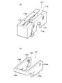
- FIG. 1 is a perspective view showing a jig body and a lever of a fitting auxiliary jig which is a premise of the fitting auxiliary jig of the present invention.
- FIG. 2 is a perspective view showing a fitting auxiliary jig and a connector which are the premise of the fitting auxiliary jig of the present invention.
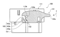
- FIG. 3 is a cross-sectional view for explaining a fitting operation of the fitting auxiliary jig which is a premise of the fitting auxiliary jig of the present invention.
- FIG. 4 is a cross-sectional view for explaining a fitting operation of the fitting auxiliary jig which is a premise of the fitting auxiliary jig of the present invention.
- FIG. 1 is a perspective view showing a jig body and a lever of a fitting auxiliary jig which is a premise of the fitting auxiliary jig of the present invention.
- FIG. 2 is a perspective view showing a
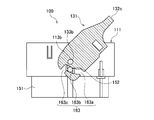
- FIG. 5 is a cross-sectional view for explaining a fitting operation of the fitting auxiliary jig which is a premise of the fitting auxiliary jig of the present invention.
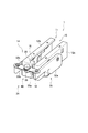
- FIG. 6 is a perspective view showing a first interval adjusting mechanism of the fitting assist jig according to the embodiment of the present invention.
- FIG. 7 is a perspective view showing a jig body according to the embodiment of the present invention.
- FIG. 8 is a perspective view showing the lever of the fitting assist jig and the second interval adjusting mechanism according to the embodiment of the present invention.
- FIG. 9 is a perspective view showing the minimum distance between the jig body and the lever according to the embodiment of the present invention.
- FIG. 10 is a perspective view showing the maximum distance between the jig body and the lever according to the embodiment of the present invention.
- FIG.1 (a) is a perspective view which shows the jig
- FIG.1 (b) is a perspective view which shows the lever 131 of the fitting assistance jig
- FIG. 2A is a perspective view showing a fitting assisting jig 100 that is a premise of the fitting assisting jig 1 according to the embodiment of the present invention.
- 2 (b) and 2 (c) show a female connector 141 and a male connector 151 that are fitted using the fitting auxiliary jig 100 which is a premise of the fitting auxiliary jig 1 according to the embodiment of the present invention. It is a perspective view shown.
- a fitting assist jig 100 which is a premise of the fitting assist jig 1 according to the embodiment of the present invention is a jig used to rotate the lever 131 to fit the male connector 151 to the female connector 141. .
- a fitting auxiliary jig 100 that is a premise of the fitting auxiliary jig 1 according to the embodiment of the present invention is a jig main body having a connector housing chamber 110 for housing a female connector 141. 111 and a lever 131 pivotally supported by the jig body 111 so as to be rotatable.
- the jig body 111 includes a first jig body 112a and a second jig body 112b that hold the female connector 141 (see FIG. 2B) from both sides, It has a jig main body connecting portion 112c for connecting the first jig main body 112a and the second jig main body 112b.
- the first jig main body 112a and the second jig main body 112b are respectively inserted into jig assembly holes 133a and 133b (see FIG. 1B) described later.
- a pair of lever mounting bosses 113a and 113b for pivotally supporting the lever 131 are provided.
- the lever 131 is rotatable about a first lever body 132a pivotally supported by the first jig body 112a and a second jig body 112b.
- a second lever main body 132b that is pivotally supported, and a lever main body connecting portion 132c that connects the first lever main body 132a and the second lever main body 132b are provided.
- the first lever main body 132a and the second lever main body 132b have a pair that engages with a pair of male connector protrusions 152 (see FIG. 2C, one side omitted) protruding from the outer side of the male connector 151.
- the male connector engaging portion 163 (see FIG. 3 described later) is formed.
- the male connector engaging portion 163 has one side 163a and the other side 163c opened at two end surfaces of the first lever main body 132a and the second lever main body 132b.
- the one side 163a and the other side 163c are connected by an intermediate portion 163b in which intervals between the jig assembly holes 133a and 133b are gradually shortened (see FIGS. 3 to 5).
- the lever mounting bosses 113a and 113b (FIG. 1 (a), see FIG. 3 to be described later) are inserted into the jig assembly holes 133a and 133b (see FIG. 1 (b)), respectively.
- the lever 131 is pivotally supported by the jig body 111 so as to be rotatable.
- the fitting assist jig 100 having the lever 131 attached to the jig main body 111 accommodates the female connector 141 (see FIG. 2B) in the connector accommodating chamber 110 and inserts it into the male connector 151. Then, the lever 131 is rotated to fit the male connector 151 to the female connector 141.
- 3 to 5 are cross-sectional views for explaining the fitting operation of the fitting auxiliary jig 100 of FIGS. 1 and 2.
- the mating auxiliary jig 100 in which the female connector 141 (see FIG. 2B) is accommodated in the connector accommodating chamber 110 is inserted into the male connector 151.
- the male connector engaging portion 163 (one side omitted) of the lever 131 is formed on each of the pair of male connector protrusions 152 (see FIG. 2C, one side omitted). Engage.
- the male connector protrusion 152 (see FIG. 2C, one side omitted) is connected to the male connector.
- One side 163a of the joint portion 163 (one side omitted) is engaged.
- tool assembly holes 133a and 133b which are the rotation centers of the lever 131 are moved by the location in the male connector engaging part 163 which the male connector protrusion 152 engages from the one end 163a to the intermediate part 163b. And the distance between the male connector protrusion 152 is shortened.
- the fitting auxiliary jig 100 can remove the lever 131 and the jig main body 111 from the female connector 141 after fitting the male connector 151 (see FIG. 2B) to the female connector 141.
- the male connector 151 can be fitted to the plurality of female connectors 141 using the fitting assist jig 100.
- the first jig main body 112a and the second jig main body 112b are connected by the jig main body connecting portion 112c, and the first lever main body 132a and the second lever main body 132b are connected. Are connected by a lever main body connecting portion 132c.
- the above-described fitting auxiliary jig 100 has a width corresponding to the distance between the first jig main body 112a and the second jig main body 112b (see the length C of one side shown in FIG. 2B). This means a fitting assist jig dedicated to the specific female connector 141.
- the fitting auxiliary jig 1 is provided with a gap adjusting mechanism in the jig main body 11 and the lever 31, and one kind of fitting auxiliary jig for female connectors having different lengths on one side. 1 can be used to fit the male connector to the female connector.
- FIG. 6 is a perspective view showing the first interval adjusting mechanism 14 of the fitting assisting jig 1 according to the embodiment of the present invention.
- FIG. 7 is a perspective view showing the jig body 11 according to the embodiment of the present invention.
- FIG. 8 is a perspective view showing the lever 31 and the second interval adjusting mechanism 34 of the fitting assisting jig 1 according to the embodiment of the present invention.
- the fitting auxiliary jig 1 is a jig used for fitting the male connector 151 to the female connector 141 by rotating the lever 31 in the same manner as the fitting auxiliary jig 100 described above. It is.
- the fitting assist jig 1 (see FIGS. 9 and 10 described later) according to the embodiment of the present invention is a connector that houses a female connector 141 (see FIG. 2B).
- a jig main body 11 having a storage chamber 10 and a lever 31 pivotally supported by the jig main body 11 are substantially constituted.
- the jig body 11 includes a first jig body 12 a and a second jig body 12 b that hold the female connector 141 (see FIG. 2B) from both sides, It has the 1st space
- the first jig main body 12a and the second jig main body 12b are respectively inserted into jig assembling holes 33a and 33b (see FIG. 8 to be described later), and the lever 31 is pivotable.
- a pair of supporting lever mounting bosses 13 (one side omitted) is provided.
- the first gap adjusting mechanism 14 is provided between the first jig body 12a and the second jig body 12b, and the first jig body 12a is connected to the second jig body 12b.
- the first positioning mechanism 20 is positioned.
- the first positioning mechanism 20 includes a slide plate 15 protruding from the first jig main body 12a and a slide groove 16 formed on the second jig main body 12b and slidably supporting the slide plate 15. Have.
- the slide plate 15 and the slide groove 16 extend along the interval direction between the first jig body 12a and the second jig body 12b.
- the slide groove 16 is formed with embedding plates 16 a and 16 b that extend from one side and the other side and hold the slide plate 15.
- the first positioning mechanism includes a first slide adjustment hole 17 formed in the slide plate 15, a second slide adjustment hole 18 formed in the slide groove 16, the first slide adjustment hole 17, and the second slide adjustment hole 17. It is comprised from the jig
- the first slide adjustment hole 17 is formed in a circular shape having a diameter substantially the same as the diameter of the axis of the jig slide adjustment screw 19, and the second slide adjustment hole 18 is an ellipse extending from one end 18a to the other end 18b. It is formed into a shape.
- the slide groove 16 supports the slide plate 15 and the first jig body.
- the interval between 12a and the second jig body 12b can be held at an arbitrary interval.
- the jig slide adjusting screw 19 By loosening the jig slide adjusting screw 19 inserted into the slide groove 16, the jig slide adjusting screw 19 can slide from one end 18a to the other end 18b while supporting the slide plate 15.
- the end surfaces of the holding plates 16a and 16b are in contact with the first jig main body 12a, and the first jig main body 12a and the second jig are fixed.
- the distance from the tool body 12b is the minimum distance (see FIG. 7).
- the distance between the first jig main body 12a and the second jig main body 12b is larger than when the jig slide adjusting screw 19 is positioned at the one end 18a. Become wider.
- the lever 31 is pivotally supported by a first lever body 32a pivotally supported by the first jig body 12a and a second jig body 12b. And a second lever main body 32b.
- the lever 31 corresponds to the distance between the first jig main body 12a and the second jig main body 12b adjusted by the first distance adjusting mechanism 14 (see FIGS. 6 and 7).
- the first lever main body 32a and the second lever main body 32b have a pair of male connector protrusions 152 (see FIG. 2 (c), one side) protruding from the outer side of the male connector 151.
- a pair of male connector engaging portions 63 (one side omitted) is formed.
- the second interval adjusting mechanism 34 is a position where interference with the jig body 11 can be avoided in the entire rotation range (see FIGS. 3 to 5) of the lever 31 with respect to the jig body 11 (see FIGS. 6 and 7). Is provided.
- the second interval adjusting mechanism 34 is provided between the first lever body 32a and the second lever body 32b.
- the lever 31 is rotated by holding the second interval adjusting mechanism 34 so that the female The male connector 151 (see FIG. 2C) can be fitted to the connector 141 (see FIG. 2B).
- the second distance adjusting mechanism 34 is provided between the first lever main body 32a and the second lever main body 32b, and positions the first lever main body 32a with respect to the second lever main body 32b. Two positioning mechanisms 40 are provided.
- the second positioning mechanism 34 is provided with a pair of lever movable plates 35a and 35b, and a lever movable plate attached to the first lever main body 32a and the second lever main body 32b, and the lever movable plates 35a and 35b are attached by screws. It has bosses 36a and 36b.
- the pair of lever movable plates 35a and 35b of the second positioning mechanism 34 has boss holes 37a and 37b attached to the lever movable plate attachment bosses 36a and 36b, respectively, and connection holes 39a and 39b into which the movable connection screws 38 are inserted. Is formed.
- the pair of lever movable plates 35a and 35b is configured by inserting the lever movable plate mounting bosses 36a and 36b into the boss holes 37a and 37b and screwing the lever movable plate mounting bosses 36a and 36b and the boss holes 37a and 37b.
- the first lever body 32a or the second lever body 32b is supported.
- the pair of lever movable plates 35a and 35b are attached between the first lever main body 32a and the second lever main body 32b by inserting the movable connection screws 38 into the connection holes 39a and 39b and fastening them.
- the pair of lever movable plates 35a and 35b are extended and bent in conjunction with an increase or decrease in the distance between the first lever main body 32a and the second lever main body 32b (see FIGS. 9 and 10).
- the first lever when the pair of lever movable plates 35a and 35b is bent (when the lever movable plates 35a and 35b are obtuse with respect to the first lever main body 32a or the second lever main body 32b), the first lever When the main body 32a and the second lever main body 32b are in contact with the first jig main body 12a and the second jig main body 12b having the minimum distance, the distance between the first lever main body 32a and the second lever main body 32b is reached. Is the minimum interval.
- the first lever The distance between the main body 32a and the second lever main body 32b is the maximum distance.
- the distance between the first jig main body 12a and the second jig main body 12b can be increased until the first lever main body 32a and the second lever main body 32b are in contact with each other.
- the pair of lever movable plates 35a, 35b configured in this manner follows the increase and decrease of the distance between the first jig body 12a and the second jig body 12b, and is stepless from the extended state to the bent state. Elongates and bends (see FIGS. 9 and 10).
- the fitting assist jig 1 having the lever 31 attached to the jig body 11 accommodates the female connector 141 (see FIG. 2B) in the connector housing chamber 10 and forms the male connector 151 (see FIG. 2C). insert. Then, the lever 31 is rotated to fit the male connector 151 to the female connector 141 (see FIGS. 3 to 5).
- the jig main body 11 holds the female connector 141 (see FIG. 2B) from both sides by the first jig main body 12a and the second jig main body 12b.
- the mating auxiliary jig can be removed from the female connector 141 and used to fit the other male and female connectors 141 and 151.
- the jig body 11 has the first gap adjusting mechanism 14 that connects the first jig body 12a and the second jig body 12b so that the gap can be adjusted, the female connectors having different widths are connected to both sides. Can be held from.
- first lever body 32a and the second lever body 32b are connected to the lever 31 so as to adjust the distance corresponding to the distance between the first jig body 12a and the second jig body 12b. Since the second distance adjusting mechanism 34 is provided, the male and female connectors 141 and 151 having different widths can be fitted.
- FIG. 9 is a perspective view showing the minimum distance between the jig body 1 and the lever 31 according to the embodiment of the present invention.
- FIG. 10 is a perspective view showing the maximum distance between the jig body 1 and the lever 31 according to the embodiment of the present invention.
- the first positioning mechanism 20 positions the first jig body 12a with respect to the second jig body 12b at the minimum distance between the jig body 11 and the lever 31.
- the holding plates 16a and 16b come into contact with the first jig body 12a (see FIG. 6), and the first jig body 12a and the second jig body 12a are in contact with each other.
- the distance between the jig body 12b and the distance between the first lever body 32a and the second lever body 32b is the minimum distance.
- the lever 31 follows the jig body 11, and the pair of lever movable plates 35a and 35b are bent.
- the first positioning mechanism 20 moves the first jig body 12a to the second position at the minimum distance between the jig body 11 and the lever 31 by positioning the jig slide adjusting screw 19 at the one end 18a. Positioning is performed with respect to the jig body 12b.
- the second positioning mechanism 40 positions the first lever body 32 a with respect to the second lever body 32 b at the maximum distance between the jig body 11 and the lever 31.
- the distance between the first lever body 32a and the second lever body 32b is the maximum distance.
- the jig main body 11 follows the lever 31, and the jig slide adjusting screw 19 is positioned at a position other than the one end 18a while supporting the slide plate 15 (for example, positioned near the other end 18b).
- the second positioning mechanism 40 is configured such that the first lever main body 32a is moved to the second lever main body at the maximum distance between the jig main body 11 and the lever 31 by extending the pair of lever movable plates 35a and 35b. Position with respect to 32b.
- the slide groove 16 has the entire range of the distance adjustment range between the first jig body 12a and the second jig body 12b (the minimum distance shown in FIG. 9). To the maximum interval shown in FIG. 10), the slide plate 15 can be slidably supported.
- the pair of lever movable plates 35a and 35b is in the entire range of the distance adjustment range between the first lever body 32a and the second lever body 32b (from the minimum distance shown in FIG. 9 to the maximum distance shown in FIG. 10). Can be extended and bent.
- the first interval adjustment mechanism 14 includes the first positioning mechanism 20 that positions the first jig body 12a with respect to the second jig body 12b, and the second interval adjustment mechanism. 34 has the 2nd positioning mechanism 40 which positions the 1st lever main body 32a with respect to the 2nd lever main body 32b. Therefore, the configuration of each positioning mechanism can be simplified as compared with the configuration for positioning at the maximum interval and the minimum interval in one of the jig body 11 and the lever 31 collectively.
- the lever 31 follows the jig body 11 and the width is adjusted.
- the jig body 11 follows the lever 31 and the width is adjusted. Therefore, the width of the female connector 141 can be easily adjusted, and the female connector 141 (FIG. 2). (See (b)) can be accommodated in the connector accommodating chamber 10.
- the auxiliary fitting jig 1 is the auxiliary fitting jig 1 used for rotating the lever 31 and fitting the male connector 151 to the female connector 141.
- the first jig main body 12a and the second jig main body 12b that hold the female connector 141 from both sides, and the first jig main body 12a and the second jig main body 12b are connected so as to be adjustable in distance.
- the lever 31 includes a first lever main body 32a pivotally supported by the first jig main body 12a, and a second jig main body.
- the second interval adjusting mechanism 34 is provided at a position where interference with the jig body 11 can be avoided in the entire rotation range of the lever 31 with respect to the jig body 11. It has been.
- the first interval adjusting mechanism 14 is configured such that the first jig is at the maximum interval or the minimum interval between the jig body 11 and the lever 31.
- the first positioning mechanism 20 for positioning the main body 12a with respect to the second jig main body 12b is provided, and the second interval adjusting mechanism 34 is either the maximum interval or the minimum interval between the jig main body 11 and the lever 31.
- a second positioning mechanism 40 is provided for positioning the first lever body 32a with respect to the second lever body 32b at the other interval.
- the jig main body 11 holds the female connector 141 from both sides by the first jig main body 12a and the second jig main body 12b. After the male connector 151 is fitted to the connector 141, the fitting auxiliary jig can be removed from the female connector 141 and used to fit the other male and female connectors 141 and 151.
- the jig body 11 has the first gap adjusting mechanism 14 that connects the first jig body 12a and the second jig body 12b so that the gap can be adjusted, the female connectors having different widths are connected to both sides. Can be held from.
- a second lever 31 is connected to the lever 31 so that the distance between the first jig body 12a and the second jig body 12b can be adjusted according to the distance between the first jig body 12a and the second jig body 12b. Therefore, the male and female connectors 141 and 151 having different widths can be fitted.
- the second interval adjusting mechanism 34 is provided at a position where interference with the jig main body 11 can be avoided.
- the male connector 151 can be fitted to the female connector 141 by rotating the lever 31 while holding the lever.
- the first interval adjusting mechanism 14 positions the first jig body 12a with respect to the second jig body 12b.
- the second spacing adjusting mechanism 34 includes a second positioning mechanism 40 that positions the first lever body 32a with respect to the second lever body 32b. Therefore, the configuration of each positioning mechanism can be simplified as compared with the configuration for positioning at the maximum interval and the minimum interval in one of the jig body 11 and the lever 31 collectively.
- the fitting auxiliary jig of the present invention has been described based on the illustrated embodiment, the present invention is not limited to this, and the configuration of each part is an arbitrary configuration having the same function. Can be replaced.
- the first positioning mechanism 20 of the fitting assist jig 1 is configured such that the first jig body 12 a is the second jig body at the minimum distance between the jig body 11 and the lever 31.
- the positioning may be performed at the maximum interval.
- the second positioning mechanism 40 of the fitting assist jig 1 positions the first lever body 32a with respect to the second lever body 32b at the maximum distance between the jig body 11 and the lever 31. However, positioning may be performed at a minimum interval.
Landscapes
- Engineering & Computer Science (AREA)
- Manufacturing & Machinery (AREA)
- Manufacturing Of Electrical Connectors (AREA)
- Details Of Connecting Devices For Male And Female Coupling (AREA)
Abstract
Description
Claims (3)
- 一方のコネクタに他方のコネクタを嵌合させるのに用いる嵌合補助治具であって、
前記一方のコネクタを両側から保持する第1の治具本体及び第2の治具本体と、前記第1の治具本体と前記第2の治具本体とを間隔調整可能に連結する第1の間隔調整機構とを有する治具本体と、
レバーであって、
前記第1の治具本体に回動可能に軸支される第1のレバー本体と、
前記第2の治具本体に回動可能に軸支される第2のレバー本体と、
前記第1の間隔調整機構により調整される前記第1の治具本体と前記第2の治具本体との間隔に対応して前記第1のレバー本体と前記第2のレバー本体とを間隔調整可能に連結する第2の間隔調整機構と、を有するレバーと、を備え、
前記レバーの回動により前記一方のコネクタと前記他方のコネクタとが嵌合される
嵌合補助治具。 - 前記第2の間隔調整機構は、前記治具本体に対する前記レバーの回動範囲の全体において前記治具本体と干渉回避可能な位置に設けられている
請求項1に記載の嵌合補助治具。 - 前記第1の間隔調整機構は、前記治具本体と前記レバーの最大間隔及び最小間隔のいずれかの間隔で、前記第1の治具本体を前記第2の治具本体に対して位置決めする第1の位置決め機構を有し、
前記第2の間隔調整機構は、前記治具本体と前記レバーの最大間隔及び最小間隔のいずれかの間隔で、前記第1のレバー本体を第2のレバー本体に対して位置決めする第2の位置決め機構を有する
請求項1又は請求項2に記載の嵌合補助治具。
Priority Applications (4)
| Application Number | Priority Date | Filing Date | Title |
|---|---|---|---|
| CN201280013644.3A CN103430402B (zh) | 2011-03-16 | 2012-03-13 | 辅助装配夹具 |
| KR1020137023491A KR101418866B1 (ko) | 2011-03-16 | 2012-03-13 | 끼워맞춤 보조 지그 |
| DE112012001223T DE112012001223T5 (de) | 2011-03-16 | 2012-03-13 | Hilfs-Einpassvorrichtung |
| US14/024,738 US8776362B2 (en) | 2011-03-16 | 2013-09-12 | Auxiliary fitting jig |
Applications Claiming Priority (2)
| Application Number | Priority Date | Filing Date | Title |
|---|---|---|---|
| JP2011-058251 | 2011-03-16 | ||
| JP2011058251A JP5662211B2 (ja) | 2011-03-16 | 2011-03-16 | 嵌合補助治具 |
Related Child Applications (1)
| Application Number | Title | Priority Date | Filing Date |
|---|---|---|---|
| US14/024,738 Continuation US8776362B2 (en) | 2011-03-16 | 2013-09-12 | Auxiliary fitting jig |
Publications (1)
| Publication Number | Publication Date |
|---|---|
| WO2012124694A1 true WO2012124694A1 (ja) | 2012-09-20 |
Family
ID=46830761
Family Applications (1)
| Application Number | Title | Priority Date | Filing Date |
|---|---|---|---|
| PCT/JP2012/056427 Ceased WO2012124694A1 (ja) | 2011-03-16 | 2012-03-13 | 嵌合補助治具 |
Country Status (6)
| Country | Link |
|---|---|
| US (1) | US8776362B2 (ja) |
| JP (1) | JP5662211B2 (ja) |
| KR (1) | KR101418866B1 (ja) |
| CN (1) | CN103430402B (ja) |
| DE (1) | DE112012001223T5 (ja) |
| WO (1) | WO2012124694A1 (ja) |
Cited By (1)
| Publication number | Priority date | Publication date | Assignee | Title |
|---|---|---|---|---|
| CN104078815A (zh) * | 2013-03-26 | 2014-10-01 | 泰科电子连接荷兰公司 | 工件载体装置 |
Families Citing this family (2)
| Publication number | Priority date | Publication date | Assignee | Title |
|---|---|---|---|---|
| JP5662208B2 (ja) * | 2011-03-16 | 2015-01-28 | 矢崎総業株式会社 | レバー治具及びコネクタ装置 |
| KR101526762B1 (ko) | 2013-12-24 | 2015-06-05 | 현대자동차주식회사 | 친환경 자동차의 부품용 커넥터 커버 및 이의 체결방법 |
Citations (7)
| Publication number | Priority date | Publication date | Assignee | Title |
|---|---|---|---|---|
| US3177567A (en) * | 1963-08-12 | 1965-04-13 | Ivor H Gehrman | Mating tool |
| JPS5275793U (ja) * | 1975-12-05 | 1977-06-06 | ||
| JPH05182739A (ja) * | 1991-12-27 | 1993-07-23 | Fujikura Ltd | 強制挿入離脱形コネクタ |
| JP2009187863A (ja) * | 2008-02-08 | 2009-08-20 | Yazaki Corp | レバー嵌合式コネクタ |
| JP2011150934A (ja) * | 2010-01-22 | 2011-08-04 | Yazaki Corp | 嵌合補助治具及びこれを用いたコネクタ |
| JP2011159574A (ja) * | 2010-02-03 | 2011-08-18 | Yazaki Corp | コネクタおよびコネクタ用治具 |
| JP2011258324A (ja) * | 2010-06-07 | 2011-12-22 | Yazaki Corp | コネクタ嵌合用治具、コネクタの嵌合方法、コネクタの嵌合構造 |
Family Cites Families (5)
| Publication number | Priority date | Publication date | Assignee | Title |
|---|---|---|---|---|
| JPS5275793A (en) | 1975-12-18 | 1977-06-25 | Hitachi Zosen Corp | Intermediate shaft bearing support for ship propulsin shaft |
| JP2531000Y2 (ja) * | 1991-10-14 | 1997-04-02 | 住友電装株式会社 | コネクタ |
| JP3730416B2 (ja) * | 1998-09-10 | 2006-01-05 | 矢崎総業株式会社 | レバー嵌合式コネクタ |
| CN200956485Y (zh) * | 2006-03-31 | 2007-10-03 | 昆达电脑科技(昆山)有限公司 | 夹持工具 |
| CN201112583Y (zh) * | 2007-08-16 | 2008-09-10 | 上海市七宝中学 | 弹簧电线夹 |
-
2011
- 2011-03-16 JP JP2011058251A patent/JP5662211B2/ja not_active Expired - Fee Related
-
2012
- 2012-03-13 CN CN201280013644.3A patent/CN103430402B/zh not_active Expired - Fee Related
- 2012-03-13 DE DE112012001223T patent/DE112012001223T5/de not_active Ceased
- 2012-03-13 KR KR1020137023491A patent/KR101418866B1/ko not_active Expired - Fee Related
- 2012-03-13 WO PCT/JP2012/056427 patent/WO2012124694A1/ja not_active Ceased
-
2013
- 2013-09-12 US US14/024,738 patent/US8776362B2/en not_active Expired - Fee Related
Patent Citations (7)
| Publication number | Priority date | Publication date | Assignee | Title |
|---|---|---|---|---|
| US3177567A (en) * | 1963-08-12 | 1965-04-13 | Ivor H Gehrman | Mating tool |
| JPS5275793U (ja) * | 1975-12-05 | 1977-06-06 | ||
| JPH05182739A (ja) * | 1991-12-27 | 1993-07-23 | Fujikura Ltd | 強制挿入離脱形コネクタ |
| JP2009187863A (ja) * | 2008-02-08 | 2009-08-20 | Yazaki Corp | レバー嵌合式コネクタ |
| JP2011150934A (ja) * | 2010-01-22 | 2011-08-04 | Yazaki Corp | 嵌合補助治具及びこれを用いたコネクタ |
| JP2011159574A (ja) * | 2010-02-03 | 2011-08-18 | Yazaki Corp | コネクタおよびコネクタ用治具 |
| JP2011258324A (ja) * | 2010-06-07 | 2011-12-22 | Yazaki Corp | コネクタ嵌合用治具、コネクタの嵌合方法、コネクタの嵌合構造 |
Cited By (1)
| Publication number | Priority date | Publication date | Assignee | Title |
|---|---|---|---|---|
| CN104078815A (zh) * | 2013-03-26 | 2014-10-01 | 泰科电子连接荷兰公司 | 工件载体装置 |
Also Published As
| Publication number | Publication date |
|---|---|
| CN103430402A (zh) | 2013-12-04 |
| JP2012195163A (ja) | 2012-10-11 |
| JP5662211B2 (ja) | 2015-01-28 |
| US20140026405A1 (en) | 2014-01-30 |
| KR20130123429A (ko) | 2013-11-12 |
| DE112012001223T5 (de) | 2013-12-19 |
| US8776362B2 (en) | 2014-07-15 |
| KR101418866B1 (ko) | 2014-07-11 |
| CN103430402B (zh) | 2015-11-25 |
Similar Documents
| Publication | Publication Date | Title |
|---|---|---|
| US6652298B2 (en) | Connector | |
| TWI510165B (zh) | 具有擴展卡模組的伺服器 | |
| TWI426199B (zh) | 夾持機構 | |
| JP5662211B2 (ja) | 嵌合補助治具 | |
| KR101360193B1 (ko) | 회전 연동구조를 구비한 광학계 렌즈 리테이너 조립용 원형 치공구 | |
| KR102502344B1 (ko) | 그립퍼 디바이스 | |
| JP2008508105A (ja) | 圧縮工具のジョーアーム | |
| CN107949799B (zh) | 镜保持机构 | |
| JP2016087409A (ja) | 組立関節、該組立関節を有する接続セット、及び該接続セットを有する組立セット | |
| JP4748821B2 (ja) | フレーム構造のコーナー部用連結装置 | |
| KR20130071774A (ko) | 배관용 클램프 | |
| EP3809548A1 (en) | Cable management assembly | |
| KR101502583B1 (ko) | 끼워맞춤 보조 지그 | |
| JP6035286B2 (ja) | 電磁弁マニホールド | |
| KR101682641B1 (ko) | 니플 벤딩용 지그 | |
| EP3381095B1 (en) | Connector demating tool and method | |
| JP5840664B2 (ja) | シートクリップ | |
| US9708838B2 (en) | Vehicle door handle device | |
| CN102689210A (zh) | 夹紧机构 | |
| JP5795183B2 (ja) | 間接活線用工具 | |
| KR102899177B1 (ko) | 배터리 모듈 | |
| JP6050085B2 (ja) | 配設体支持具及び配設体設置構造 | |
| JP5110705B2 (ja) | 照明器具 | |
| CA2829546A1 (en) | Pipe clamping device | |
| JP7465729B2 (ja) | 電線接続具 |
Legal Events
| Date | Code | Title | Description |
|---|---|---|---|
| 121 | Ep: the epo has been informed by wipo that ep was designated in this application |
Ref document number: 12757163 Country of ref document: EP Kind code of ref document: A1 |
|
| ENP | Entry into the national phase |
Ref document number: 20137023491 Country of ref document: KR Kind code of ref document: A |
|
| WWE | Wipo information: entry into national phase |
Ref document number: 112012001223 Country of ref document: DE Ref document number: 1120120012232 Country of ref document: DE |
|
| 122 | Ep: pct application non-entry in european phase |
Ref document number: 12757163 Country of ref document: EP Kind code of ref document: A1 |