WO2012124611A1 - 電動機の冷却媒体排出構造及び電動機 - Google Patents
電動機の冷却媒体排出構造及び電動機 Download PDFInfo
- Publication number
- WO2012124611A1 WO2012124611A1 PCT/JP2012/056030 JP2012056030W WO2012124611A1 WO 2012124611 A1 WO2012124611 A1 WO 2012124611A1 JP 2012056030 W JP2012056030 W JP 2012056030W WO 2012124611 A1 WO2012124611 A1 WO 2012124611A1
- Authority
- WO
- WIPO (PCT)
- Prior art keywords
- cooling medium
- discharge port
- discharge
- electric motor
- passage
- Prior art date
- Legal status (The legal status is an assumption and is not a legal conclusion. Google has not performed a legal analysis and makes no representation as to the accuracy of the status listed.)
- Ceased
Links
Images





Classifications
-
- H—ELECTRICITY
- H02—GENERATION; CONVERSION OR DISTRIBUTION OF ELECTRIC POWER
- H02K—DYNAMO-ELECTRIC MACHINES
- H02K9/00—Arrangements for cooling or ventilating
- H02K9/19—Arrangements for cooling or ventilating for machines with closed casing and closed-circuit cooling using a liquid cooling medium, e.g. oil
-
- H—ELECTRICITY
- H02—GENERATION; CONVERSION OR DISTRIBUTION OF ELECTRIC POWER
- H02K—DYNAMO-ELECTRIC MACHINES
- H02K5/00—Casings; Enclosures; Supports
- H02K5/04—Casings or enclosures characterised by the shape, form or construction thereof
- H02K5/16—Means for supporting bearings, e.g. insulating supports or means for fitting bearings in the bearing-shields
- H02K5/173—Means for supporting bearings, e.g. insulating supports or means for fitting bearings in the bearing-shields using bearings with rolling contact, e.g. ball bearings
- H02K5/1732—Means for supporting bearings, e.g. insulating supports or means for fitting bearings in the bearing-shields using bearings with rolling contact, e.g. ball bearings radially supporting the rotary shaft at both ends of the rotor
-
- H—ELECTRICITY
- H02—GENERATION; CONVERSION OR DISTRIBUTION OF ELECTRIC POWER
- H02K—DYNAMO-ELECTRIC MACHINES
- H02K5/00—Casings; Enclosures; Supports
- H02K5/04—Casings or enclosures characterised by the shape, form or construction thereof
- H02K5/20—Casings or enclosures characterised by the shape, form or construction thereof with channels or ducts for flow of cooling medium
- H02K5/203—Casings or enclosures characterised by the shape, form or construction thereof with channels or ducts for flow of cooling medium specially adapted for liquids, e.g. cooling jackets
-
- H—ELECTRICITY
- H02—GENERATION; CONVERSION OR DISTRIBUTION OF ELECTRIC POWER
- H02K—DYNAMO-ELECTRIC MACHINES
- H02K9/00—Arrangements for cooling or ventilating
- H02K9/19—Arrangements for cooling or ventilating for machines with closed casing and closed-circuit cooling using a liquid cooling medium, e.g. oil
- H02K9/193—Arrangements for cooling or ventilating for machines with closed casing and closed-circuit cooling using a liquid cooling medium, e.g. oil with provision for replenishing the cooling medium; with means for preventing leakage of the cooling medium
-
- H—ELECTRICITY
- H02—GENERATION; CONVERSION OR DISTRIBUTION OF ELECTRIC POWER
- H02K—DYNAMO-ELECTRIC MACHINES
- H02K9/00—Arrangements for cooling or ventilating
- H02K9/26—Structural association of machines with devices for cleaning or drying cooling medium, e.g. with filters
-
- H—ELECTRICITY
- H02—GENERATION; CONVERSION OR DISTRIBUTION OF ELECTRIC POWER
- H02K—DYNAMO-ELECTRIC MACHINES
- H02K2205/00—Specific aspects not provided for in the other groups of this subclass relating to casings, enclosures, supports
- H02K2205/09—Machines characterised by drain passages or by venting, breathing or pressure compensating means
Definitions
- the present invention relates to a cooling medium discharge structure for an electric motor that cools the electric motor with oil and the electric motor.
- the motor is used for various purposes, it generates heat due to the Joule heat generation of the coil of the stator and the eddy current loss and hysteresis loss of the rotor core.
- a technique for cooling the electric motor using a cooling medium such as oil is described (Patent Document 1).
- Patent Document 1 has a cooling liquid outlet for discharging a cooling liquid (cooling medium) from the electric motor (electric motor), and the cooling liquid outlet is a motor housing ( Therefore, the cooling liquid at the bottom may not be completely discharged during the cooling of the electric motor. As a result, the cooling medium may remain in the casing of the electric motor, and a non-replaceable cooling medium may be generated.
- An object of the present invention is to reduce a cooling medium that stays in a casing of an electric motor and is not discharged when the electric motor is cooled by the cooling medium.
- the present invention supports the shaft via a bearing and discharges a cooling medium that has cooled an electric motor in which a shaft to which a rotor core is attached in the housing is disposed, and one end of the housing.
- a first discharge port through which the cooling medium in the housing passes, and a bearing provided in the end side member and supported by the end side member.
- a second discharge port through which the cooling medium in the casing that has passed through the passage passes, and a discharge passage that discharges the cooling medium that has passed through the first discharge port and the second discharge port to the outside of the casing.
- a cooling medium discharge structure for an electric motor is provided for an electric motor.
- an opening area of the first discharge port is larger than an opening area of the second discharge port.
- the first discharge port is provided on the inner side of the inner peripheral surface of the casing.
- the discharge passage extends toward the radially outer side of the shaft.
- the first discharge port has a dimension in a direction parallel to the radial direction of the shaft larger than a dimension in a direction orthogonal to the radial direction of the shaft.
- the end portion side member is a disk-shaped member attached to one end portion of the casing.
- the discharge passage has a filter for removing foreign substances from the cooling medium.
- the discharge passage is common to the first discharge port and the second discharge port.
- the present invention is an electric motor comprising the cooling medium discharge structure of the electric motor.
- the present invention relates to an electric motor that rotationally drives an upper rotating body of a construction machine in which a shaft to which a rotor core is attached is disposed in a housing, supports the shaft via a bearing, and one end of the housing A first discharge port that is provided on an inner side of the inner peripheral surface of the housing and allows a cooling medium in the housing to pass; and provided on the end member.
- a discharge passage for discharging the cooling medium that has passed through the discharge port and the second discharge port to the outside of the housing, wherein the first discharge port has an opening area of the second discharge port. Larger than the area, in a direction perpendicular to the radial direction of the shaft Kicking it towards the dimension in the radial direction parallel to the direction of the shaft is greater than the dimension is an electric motor characterized by.
- the present invention can reduce the cooling medium that stays in the casing of the motor and is not discharged when the motor is cooled by the cooling medium.
- FIG. 1 is a plan view showing a hybrid hydraulic excavator using the electric motor according to this embodiment as an electric motor for turning.
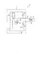
- FIG. 2 is a schematic diagram showing a cooling structure of the electric motor according to the present embodiment.
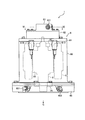
- FIG. 3 is a front view showing the electric motor according to the present embodiment.
- FIG. 4 is a plan view of the electric motor according to the present embodiment.
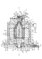
- FIG. 5 is a VV arrow view of FIG. 6 is a view taken in the direction of arrows VI-VI in FIG.
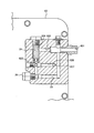
- FIG. 7 is an AA arrow view of FIG.
- FIG. 8 is a BB arrow view of FIG.
- FIG. 9 is a view taken along the line CC of FIG.
- FIG. 10 is a conceptual diagram showing a liquid level state of the cooling medium in a state where the electric motor is inclined with respect to the horizontal plane.
- FIG. 1 is a plan view showing a hybrid hydraulic excavator using the electric motor according to this embodiment as an electric motor for turning.
- the hybrid excavator 10 includes a pair of left and right crawler belts 11 forming a lower traveling body, an upper swing body 12, a swing circle 13 connecting the lower traveling body and the upper swing body 12, and an electric motor 1 functioning as a swing motor,
- the swing pinion 1 ⁇ / b> A includes a boom 14, an arm 15, and a bucket 16, and a work machine 17 attached to the upper swing body 12.
- the pair of left and right crawler belts 11 are driven by a right traveling hydraulic motor and a left traveling hydraulic motor to cause the hybrid excavator 10 to travel.
- the upper turning body 12 is turned by the electric motor 1 that functions as a turning motor.
- An outer race of a swing circle 13 is fixed to the upper swing body 12, and an inner race of the swing circle 13 is fixed to the lower traveling body. With such a structure, the swing circle 13 connects the upper swing body 12 and the lower traveling body.
- the electric motor 1 is installed vertically, that is, when the hybrid excavator 10 is installed on a horizontal plane, the input / output shaft of the electric motor 1 is directed in the direction in which gravity acts.
- the input / output shaft of the electric motor 1 is connected to the swing pinion 1A through a swing machinery having a speed reduction mechanism.
- the swing pinion 1 ⁇ / b> A meshes with internal teeth attached to the inner race of the swing circle 13.
- the driving force of the electric motor 1 is transmitted to the swing pinion 1A through the swing machinery and turns the upper swing body 12.
- the boom 14, the arm 15 and the bucket 16 are driven by hydraulic cylinders for the boom 14, the arm 15 and the bucket 16 through hydraulic control oil fed from a hydraulic pump (not shown), respectively, for excavation and the like. Perform work.
- the hybrid excavator 10 drives the generator and the hydraulic pump with the internal combustion engine, and drives the electric motor 1 through an inverter (not shown) with the electric power of the generator to turn the upper swing body 12. Further, the hybrid excavator 10 uses the electric motor 1 as a generator to generate a braking force necessary for stopping the upper swing body 12, and the electric power generated by the electric motor 1 by the braking force Store in power storage devices such as secondary batteries. Thus, the hybrid excavator 10 is a so-called hybrid construction vehicle. In this embodiment, although the example which used the electric motor 1 as a turning motor of the hybrid hydraulic shovel 10 which is a kind of construction vehicle is demonstrated, the application object of the electric motor 1 is not limited to this. Hybrid hydraulic excavator 10 may be of a system that does not have an internal combustion engine, that is, a system that is driven by electric power of a power storage device. Next, the electric motor according to the present embodiment will be described.
- FIG. 2 is a schematic diagram showing a cooling structure of the electric motor according to the present embodiment.
- the electric motor 1 is cooled by a cooling medium such as oil, for example, and lubricates the bearing 7B with the cooling medium.
- the cooling structure 2 of the electric motor 1 includes a pump 21, a pump electric motor 5, a passage 22, a bearing passage 23, a rotor passage 28, an oil reservoir 39, a discharge passage 32, a filter 24, a relief, A passage 25, a relief valve 26, and a filter 38 are included.
- a cooler for cooling the cooling medium may be provided between the filter 38 and the pump 21.
- the pump 21 and the pump motor 5 are connected by an input / output shaft 5 ⁇ / b> A of the pump motor 5.
- the drive means of the pump 21 may be other than the pump electric motor 5, and may be, for example, an internal combustion engine that is a power generation source of the hybrid excavator 10 shown in FIG.
- the filter 24 and the filter 38 are built in the electric motor 1.
- the pump motor 5 drives the pump 21. Then, the pump 21 sucks the cooling medium from the discharge passage 32 and discharges it to the passage 22. In the course of passing through the filter 24, the cooling medium removes foreign matters and the like, and flows into the bearing passage 23 and the rotor passage 28.
- the cooling medium flowing into the bearing passage 23 is collected in the discharge passage 32 after the bearing 7B is cooled and lubricated.
- the cooling medium flowing into the rotor passage 28 is collected in the discharge passage 32 after cooling the rotor core and coil of the electric motor 1.
- the cooling medium collected in the discharge passage 32 is removed of foreign matter by the filter 38, sucked by the pump 21 again, and discharged to the passage 22.
- the passage 22 is connected to the discharge port of the pump 21 and branches into the inlet side of the filter 24 and the relief passage 25 in the electric motor 1.
- the passage through which the cooling medium provided on the outlet side of the filter 24 passes branches into a bearing passage 23 and a rotor passage 28.
- the bearing passage 23 supplies a cooling medium to the bearing 7B to cool and lubricate it.
- the rotor passage 28 supplies a cooling medium to the rotor of the electric motor 1 and cools it.
- the cooling structure 2 does not necessarily have the bearing passage 23.
- the cooling medium that cools the bearing 7 ⁇ / b> B and the rotor passage 28 is collected in the oil reservoir 39.
- the discharge passage 32 connects the oil reservoir 38 and the filter 39.
- the cooling medium collected in the oil reservoir 39 passes through the filter 38 in the discharge passage 32.
- the filter 38 and the inlet side of the pump 21 are connected by a passage through which the cooling medium passes, and the cooling medium that has passed through the filter 38 is sucked into the pump 21.
- a relief passage 25 branched from the passage 22 is connected to the inlet of the relief valve 26.
- the outlet side of the relief valve 26 is connected to the outlet side of the filter 24.
- the pressure in the passage 22 and the relief passage 25 increases.
- the relief valve 26 opens.
- the relief valve 26 bypasses the filter 24 and causes the cooling medium to flow through the bearing passage 23 and the rotor passage 28.
- the relief valve 26 causes the cooling medium to flow through the bearing passage 23 and the rotor passage 28 to cool and lubricate the bearing 7B, the rotor core, etc. Can maintain the cooling.
- FIG. 3 is a front view showing the electric motor according to the present embodiment.
- FIG. 4 is a plan view of the electric motor according to the present embodiment.
- FIG. 5 is a VV arrow view of FIG. 6 is a view taken in the direction of arrows VI-VI in FIG.
- the electric motor 1 is disposed inside a cylindrical housing 6 as a shaft 8 as an input / output shaft, a rotor core 82 attached to the shaft 8, and an outer peripheral portion of the rotor core 82.
- the shaft 8 has bearings 7A and 7B attached to both sides thereof, and is rotatably supported by the housing 6 via the bearings 7A and 7B.
- the housing 6 includes a side portion 66 that is a cylindrical member, and a first flange 65 as an end portion side member that is attached to one end portion of the side portion 66 (an end portion on the input / output side of the shaft 8). And a disc-shaped second flange 61 attached to the other end of the side portion 66. A space surrounded by the side portion 66, the first flange 65, and the second flange 61 is the inside of the housing 6.
- the first flange 65 is disposed below (on the direction side where gravity acts, and in the direction indicated by the arrow G in FIGS. 3 and 5) in a state where the electric motor 1 is used. For example, when the electric motor 1 is mounted on the hybrid excavator 10 shown in FIG. 1, the state where the hybrid excavator 10 is in contact with the horizontal plane is the state in which the electric motor 1 is used, and the lower position in that state.
- the first flange 65 is disposed on the front side.
- the side portion 66 is a member having an inner peripheral surface that is cylindrical.
- the side portion 66 has a cooling water inlet 613 for introducing water for cooling the electric motor 1 into a water jacket, which will be described later, and a cooling water outlet 614 for discharging the cooling water from the water jacket.
- a cooling medium other than water, such as oil, may be introduced into the water jacket to cool the electric motor 1.
- the first flange 65 is a disk-shaped member.
- the first first flange 65 has a cooling medium discharge port 651 for discharging the cooling medium from the inside of the housing 6 and guiding it to the pump 21 shown in FIG. 2 during operation of the electric motor 1. Further, the first flange 65 has a drain port 652 for extracting the cooling medium in the housing 6 when the electric motor 1 is maintained and inspected.
- the first flange 65 as an end portion side member is disposed at one end portion of the housing 6 and the shaft 8 passes therethrough. A power transmission joint or a reduction gear input shaft or the like is attached to the shaft 8 penetrating from the first flange 65.
- the first flange 65 is a separate member from the side portion 66, but the first flange 65 and the side portion 66 may be manufactured as the same member.
- the second flange 61 is arranged on the upper side, that is, on the side opposite to the direction in which the gravity acts in the state where the electric motor 1 is used.
- the second flange 61 includes a convex part 62, a cooling medium distribution part 63, and a cooling medium inlet 631.
- the cooling medium inlet 631 is for introducing the cooling medium discharged from the pump 21 shown in FIG.
- the cooling medium inlet 631 is connected to the cooling medium distributor 63.
- the bearing 7 ⁇ / b> A attached to the shaft 8 is attached to the first flange 65, and the bearing 7 ⁇ / b> B is attached to the second flange 61.
- the bearing 7 ⁇ / b> A is disposed on the first flange 65 side, that is, on the input / output side of the shaft 8 of the electric motor 1.
- the shaft 8 is rotatably supported by the housing 6 by two bearings 7A and 7B provided on both sides, and rotates about the rotation center axis Zr.
- the rotation center axis Zr is the center axis of the shaft 8.
- the rotor core 82 attached to the outer periphery of the shaft 8 is a structure in which a plurality of steel plates (electromagnetic steel plates) are laminated.
- the rotor core 82 is sandwiched between balance plates 83 and 84 from both sides in the direction in which the steel plates are laminated (lamination direction).
- the balance plates 83 and 84 are attached to the shaft 8 so as to prevent the plurality of steel plates constituting the rotor core 82 from being separated, and apply compressive force to the plurality of steel plates.
- the balance plate 84 on the first flange 65 side is disposed on the first flange 65 side, that is, on the input / output side of the shaft 8 of the electric motor 1.
- a stator 9 is disposed on the outer periphery of the rotor core 82.
- the stator 9 is attached to the inner peripheral portion of the side portion 66 of the housing 6.
- the stator 9 is a structure in which a coil 92 is wound around a stator core 91.
- a portion protruding from the stator core 91 of the coil 92 is a coil end.
- the stator core 91 is a structure in which a plurality of steel plates (magnetic steel plates) are stacked.
- the shaft 8 includes an axial passage 811 extending along the central axis, and a plurality of radial passages 812 extending from the axial passage 811 toward the radially outer side of the shaft 8 and opening on the surface of the shaft 8.
- the axial passage 811 and the radial passage 812 serve as the in-shaft cooling medium passage 813.
- the balance plate 84 has a recess 841 on the side in contact with the rotor core 82.
- the rotor core 82 has a rotor core through hole 821 that passes through the rotor core 82 in the stacking direction of the plurality of steel plates, that is, in the central axis direction of the shaft 8.
- the rotor core 82 has a plurality of permanent magnets (not shown).
- the balance plate 83 on the second flange 61 side has a balance plate through hole 831 directed in the direction of the central axis of the shaft 8.
- the in-shaft cooling medium passage 813, the recess 841, the rotor core through-hole 821 and the balance plate through-hole 831 communicate with each other to form a passage through which the cooling medium passes.
- These are provided on the shaft 8 and the rotor core 82, which are rotating bodies, and serve as a rotating body side cooling medium passage through which the cooling medium passes.
- the convex portion 62 of the second flange 61 has a through hole 621.
- the through hole 621 has a connecting member 64 for supplying a cooling medium from the stationary system to the shaft 8 that is a rotating system.
- the connecting member 64 has a cooling medium introduction passage 641 penetrating the inside.
- the cooling medium introduction passage 641 faces the opening of the axial passage 811 of the shaft 8 and introduces the cooling medium into the axial passage 811.
- the convex portion 62 has a bearing-side passage 623 that supplies a cooling medium to the bearing 7B.
- the bearing 7 ⁇ / b> B is supplied with a cooling medium from the bearing-side passage 623.
- the cooling medium distribution part 63 attached to the convex part 62 includes a first cooling medium distribution path 633 that distributes the cooling medium from the cooling medium inlet 631, a second cooling medium distribution path 635, and a first cooling medium distribution path 635.
- Three cooling medium distribution passages 636 and a fourth cooling medium distribution passage 637 are provided.
- the cooling medium distribution unit 63 includes a filter storage unit 634 that stores the filter 24, a relief passage 25, and a relief valve 26.
- the cooling medium inlet 631 is connected to the filter storage unit 634 via the first cooling medium distribution passage 633.
- the second cooling medium distribution passage 635 is connected to the filter storage unit 634 and introduces part of the cooling medium that has passed through the filter 24 into the cooling medium introduction passage 641 of the connecting member 64.
- the second cooling medium distribution passage 635 and the cooling medium introduction passage 641 correspond to the rotor passage 28 shown in FIGS.
- the third cooling medium distribution passage 636 is connected to the filter storage unit 634, and introduces the remainder of the cooling medium that has passed through the filter 24 and is introduced into the cooling medium introduction passage 641 into the fourth cooling medium distribution passage 637.
- the third cooling medium distribution passage 636, the fourth cooling medium distribution passage 637, and the bearing side passage 623 correspond to the bearing passage 23 shown in FIGS.
- the relief passage 25 connects the cooling medium inlet 631 and the relief valve 26.
- the relief valve 26 is interposed between the relief passage 25 and the second cooling medium distribution passage 635 and the third cooling medium distribution passage 636 so as to bypass the filter 24.
- the relief valve 26 is opened, and the cooling medium from the cooling medium inlet 631 is bypassed by the filter 24 and the second cooling medium distribution passage 635 and It flows into the third cooling medium distribution passage 636.
- the valve opening pressure of the relief valve 26 can be set, for example, to the pressure in the relief passage 25 when the filter 24 is clogged and needs to be replaced.
- the cooling medium can be reliably supplied to the bearing 7B, the rotor core 82, and the like. Further, when the valve opening pressure of the relief valve 26 is set as described above and a means for notifying that the relief valve 26 is opened is prepared, the replacement timing of the filter 24 can be determined by opening the relief valve 26. Can be notified.
- the supply of the cooling medium is not affected by the rotation of the rotor core 82. For this reason, the fluctuation
- This cooling medium passes through the radial passage 812 and flows into the rotor core through-hole 821 through the recess 841 of the balance plate 84.
- the cooling medium cools the rotor core 82 and a permanent magnet (not shown) in the process of passing through the rotor core through hole 821, and then flows out from the balance plate through hole 831 of the balance plate 83.
- the cooling medium flowing out from the balance plate through hole 831 is supplied to the coil end of the stator 9 (the portion where the coil 92 protrudes from the stator core 91) by centrifugal force.
- This cooling medium cools the stator 9 in the process of flowing downward in the housing 6, and is collected in the first discharge port 27 provided on the inner side of the housing 6 of the first flange 65.
- the symbol OL in FIG. 5 indicates the liquid level of the cooling medium accumulated in the oil reservoir 39.
- the amount of the cooling medium accumulated in the oil reservoir 39 is such that the part of the coil end protruding toward the first flange is always immersed so that the cooling medium discharge port 651 is immersed.
- the coil end is adjusted to cool the coil end.
- the cooling medium supplied from the cooling medium inlet 631 of the cooling medium distributor 63 and passing through the filter 24 the cooling medium that has not flowed into the rotor passage 28 flows into the bearing passage 23 and is supplied to the bearing 7B. Is done.
- the cooling medium flows downward in the housing 6 after cooling and lubricating the bearing 7B.
- the rotor core 82 and a permanent magnet (not shown) are contacted and cooled. A part of the cooling medium in contact with the rotor core 82 is supplied to the stator 9 radially outside the rotor core 82 by the centrifugal force to cool it.
- the cooling medium that has cooled the stator 9 flows downward in the housing 6 and is collected in an oil reservoir 39 provided on the inner side of the housing 6 of the first flange 65.
- the cooling medium collected in the oil reservoir 39 passes through the space between the inner ring, the outer ring, and the rolling elements of the bearing 7A and flows into a second discharge port 30 described later. As a result, the cooling medium collected in the oil reservoir 39 cools and lubricates the bearing 7A.
- the cooling medium cools the rotor core 82 and the stator 9 and cools and lubricates the bearings 7A and 7B.
- the cooling water is supplied from the cooling water inlet 613 to the water jacket 612 included in the side portion 66 of the housing 6.
- This cooling water mainly cools the stator 9 via the housing 6.
- a gasket 35 is provided between the first flange 65 and the side portion 66 as a sealing member for sealing the water jacket 612.
- the gasket 35 prevents the cooling medium inside the housing 6 from flowing out between the side portion 66 and the first flange 65 and entering the water jacket 612 or flowing out of the housing 6. It also has a function as an oil seal.
- FIG. 7 is an AA arrow view of FIG.
- FIG. 8 is a BB arrow view of FIG.
- FIG. 9 is a view taken along the line CC of FIG.
- FIG. 10 is a conceptual diagram showing a liquid level state of the cooling medium in a state where the electric motor is inclined with respect to the horizontal plane.
- the electric motor cooling medium discharge structure (hereinafter referred to as a discharge structure as needed) 100 includes a first discharge port 27, a second discharge port 30, and a discharge passage 32.
- the first flange 65 is a disk-shaped structure.
- the 1st flange 65 has the circular-arc-shaped convex part 65T which protrudes from one surface.
- a step for supporting the bearing 7A is formed on the radially inner side of the convex portion 65T. After the bearing 7A is housed in the step, it is fixed to the first flange 65 with a C-ring (C-shaped plate member) 37.
- the first discharge port 27 is provided on the radially outer side of the convex portion 65.
- the 1st discharge port 27 is a part opened to the position (the one surface which the 1st flange 65 has) lower than the top part (part where C ring 37 contacts convex part 65) of convex part 65T.
- the second discharge port 30 is provided on the radially inner side of the convex portion 65, and the cooling medium that has passed through the bearing 7 ⁇ / b> A from the inside of the housing 6 of the electric motor 1, more specifically, from the oil reservoir 39, to the discharge passage 32. It is the part that flows out.
- the first discharge port 27 is disposed at one end portion of the housing 6 and is provided in the end side member (the first flange 65 in the present embodiment) through which the shaft passes to cool the first discharge port 27. Let the media pass.
- the first discharge port 27 opens to the oil reservoir 39 of the housing 6, in this embodiment, the first flange 65 as the end portion side member, and passes the cooling medium in the housing 6 to the discharge passage 32. It is a part to be made.
- the second discharge port 30 is provided in the end side member (first flange 65 in the present embodiment), and is a cooling medium for the oil reservoir 39 that has passed through the bearing 7A, that is, a cooling medium in the housing 6. Pass through.
- the discharge passage 32 discharges the cooling medium that has passed through the first discharge port 27 and the second discharge port 30 to the outside of the housing 6.
- a space (outer bearing space) 29 through which the cooling medium in the housing 6 flows out from the bearing 7A is provided on the radially inner side of the convex portion 65T of the first flange 65.
- a cooling medium is interposed between the first flange 65 and the shaft 8.
- a seal 34 is provided. The seal 34 is interposed between the first flange 65 and the shaft 8 to suppress leakage of the cooling medium.
- the bearing outer space 29 is a space surrounded by the first flange 65, the bearing 7 ⁇ / b> A, and the seal 34.
- the second discharge port 30 is a portion where a discharge passage 32 opens in the bearing outer space 29.
- the bearing outer space 29 is disposed closer to one end of the shaft 8 than the portion where the cooling medium flows out from the bearing 7A.
- the second discharge port 30 is a part through which the cooling medium in the housing 6 (more specifically, the oil sump 39 of the housing 6) that has passed through the bearing 7A is passed to the discharge passage 32.
- the electric motor 1 does not necessarily have the bearing outer space 29.
- the second discharge port 30 is a portion that is provided between the bearing 7A and the discharge passage 32 and allows the cooling medium in the housing 6 that has passed through the bearing 7A to pass through the discharge passage 32.
- the discharge passage 32 includes a first discharge passage 31A and a second discharge passage 31B.
- the first discharge passage 31 ⁇ / b> A is a passage connected to the second discharge port 30, and is a portion connecting the second discharge port 30 to the first discharge port 27.
- the second discharge passage 31 ⁇ / b> B is a passage connected to the first discharge port 27, and is a portion on the downstream side of the first discharge port 27 in the flow direction of the cooling medium.
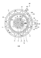
- the first discharge port 27 opens to the housing 6 side of the first flange 65, as shown in FIGS. In FIG. 8, the 1st discharge port 27 is a part shown by hatching.
- the first discharge port 27 communicates with the discharge passage 32, and the cooling medium that has passed through the first discharge port 27 flows into the discharge passage 32.
- the discharge passage 32 is connected to the cooling medium discharge port 651.
- the cooling medium that has passed through the discharge passage 32 passes through the cooling medium discharge port 651, is sucked into the pump 21 shown in FIG. 2, is discharged into the passage 22 shown in FIG.
- the first flange 65 also has a drain discharge port 27D connected to the drain port 652 via the drain passage 32D.
- drain discharge port 27D and the drain passage 32D are connected to the first discharge port 32D.
- the structure is the same as that of the outlet 27 and the discharge passage 32.
- the drain discharge port 27D and the drain passage 32D are provided separately from the first discharge port 27 and the discharge passage 32, but the drain discharge port 27D and the drain passage 32D may not be provided. .
- the drain port 652 shown in FIG. 3 is also unnecessary.
- the drain branch passage (pipe) is connected to the passage (pipe) on the mounting target (for example, construction vehicle) side of the electric motor 1 connected to the cooling medium discharge port 651. Provide branch piping).
- draining is performed using the first discharge port 27, the discharge passage 32, and the branch passage. In this way, it is not necessary to form the drain outlet 27D and the drain passage 32D in the first flange 65, so that it is possible to reduce the labor of processing and to suppress the strength reduction of the first flange 65.
- the second discharge port 30 is a portion where the cooling medium flowing out from the bearing 7A flows into the discharge passage 32 (more specifically, the first discharge passage 31A).
- FIG. 8 shows a BB cross section of FIG. 5. In this cross section, an outer ring 7o of the bearing 7A, a part of a ball (rolling element) 7b, and an inner ring 7i appear. A bearing outer space 29 appears between the balls 7b. Further, a second discharge port 30 is opened in the bearing outer space 29. The cooling medium that has passed through the second discharge port 30 flows into the discharge passage 32 (more specifically, the first discharge passage 31A).
- the cooling medium that has flowed into the discharge passage 32 passes through the cooling medium discharge port 651 and is sucked into the pump 21 shown in FIG. 2, then discharged into the passage 22 shown in FIG.
- the passage sectional area of the first discharge passage 31A and the passage sectional area of the second discharge passage 31B may be the same size or different.
- the drain passage 32D is connected to the second drain outlet 30D. When the cooling medium is extracted from the housing 6, the cooling medium that has passed through the second drain outlet 30D flows into the drain passage 32D.
- the discharge passage 32 is common to the first discharge port 27 and the second discharge port 30. If the first discharge port 27 and the second discharge port 30 have separate discharge passages, the processing of the first flange 65 will increase, but the first discharge port 27 and the second discharge port 30 will discharge. If the passage 32 is made common, the processing can be reduced. Moreover, since the number of discharge passages can be reduced by using the discharge passages 32 in common, it is possible to suppress a decrease in strength of the first flange 65. Further, if the first discharge port 27 and the second discharge port 30 have separate discharge passages, it is necessary to provide each discharge port on the side surface of the first flange 65, and thus the number of pipes increases.
- the discharge passage 32 is shared by the first discharge port 27 and the second discharge port 30, a single discharge port can be provided on the side surface of the first flange 65, thereby reducing the number of pipes. It is possible and preferable.
- the 1st discharge port 27 and the 2nd discharge port 30 may have a discharge path separately, respectively.
- the discharge structure 100 is formed from the surface of the first flange 65 on the inner side of the housing 6, that is, from the first discharge port 27 provided below the inside of the housing 6, through the discharge passage 32.
- the cooling medium is discharged.
- the discharge structure 100 can guide the cooling medium to the first discharge port 27 using the action of gravity, the cooling medium that remains in the housing 6 and is not discharged can be reduced.
- the discharge structure 100 can reliably discharge the cooling medium in the housing 6 to the outside while minimizing the cooling medium staying in the housing 6.
- the discharge structure 100 discharges the cooling medium that has passed through the bearing 7 ⁇ / b> A from the second discharge port 30 and has flowed into the bearing outer space 29 from the discharge passage 32. For this reason, the cooling medium accumulated in the bearing outer space 29 can be reliably discharged.
- varnish covering the coil 92 of the stator 9 cutting scraps such as metal scraps from the sliding portion of the electric motor 1, wear powder of the bearings 7 ⁇ / b> A and 7 ⁇ / b> B, etc. are likely to accumulate as foreign matters.
- the electric motor 1 since a part of the coil 92 is immersed in the cooling medium, the foreign matter tends to accumulate in the outer bearing space 29.
- the discharge structure 100 connects the second discharge port 30 and the discharge passage 32, and discharges the cooling medium of the second discharge port 30 from the discharge passage 32 to the outside of the housing 6.
- the cooling structure 2 can more effectively suppress a decrease in durability of the seal 34 and the bearing 7A.
- the discharge structure 100 can effectively suppress a decrease in the durability of the bearing 7A.
- the discharge structure 100 can discharge the cooling medium in the bearing 7 ⁇ / b> A and the bearing outer space 29 together with the foreign matter, so that the possibility of galling or scratches caused by the foreign matter existing in the cooling medium can be reduced.
- the bearing on the vertical side the bearing corresponding to the bearing 7A of the electric motor 1 flows down from above, that is, from the opposite side to the vertical direction. Cooled and lubricated by a cooling medium.
- the discharge structure 100 is applied to the electric motor 1 having the oil reservoir 39 in the housing 6, but the discharge structure 100 is also applied to an electric motor that does not have the oil reservoir 39. it can. Even in this case, the discharge structure 100 can discharge the cooling medium in the lower bearing and the bearing outer space 29 together with the foreign matter, so that the bearing may cause galling or scratches due to the foreign matter existing in the cooling medium. Can be reduced.
- the side portion 66 of the housing 6 has a water jacket 612, but the discharge structure 100 is provided with the discharge passage 32 in the first flange 65.
- the discharge passage 32 is provided in the first flange 65.
- the thickness of the first flange 65 is slightly increased, but the length of the side portion 66 of the housing 6 can be reduced accordingly. For this reason, the dimension increase of the electric motor 1 is suppressed.
- the second discharge port 30 has a larger pressure loss than the first discharge port 27.
- the flow rate of the cooling medium passing through the first discharge port 27 becomes larger than the flow rate of the cooling medium passing through the second discharge port 30.
- the flow rate of the cooling medium passing through the first discharge port 27 is made larger than that of the second discharge port 30, whereby the resistance when the cooling medium is sucked from the discharge passage 32 can be reduced.
- the work amount of the pump 21 shown in FIG. 2 can be reduced, so that energy consumption of the pump 21 can be suppressed.
- the flow rate of the cooling medium passing through the second discharge port 30 is smaller than that of the first discharge port 27.
- the opening area SC of the second discharge port 30 is preferably set such that the flow rate of the cooling medium passing through the second discharge port 30 is the minimum flow rate necessary for lubrication and cooling of the bearing 7A.
- the inner diameter of the first discharge passage 31A is D1, the inner diameter D2 of the second discharge passage 31B, and a cross section of these passages (a cross section orthogonal to the direction in which the first discharge passage 31A and the second discharge passage 31B extend).
- D1 the inner diameter of the first discharge passage 31A
- D2 the second discharge passage 31B
- a cross section of these passages a cross section orthogonal to the direction in which the first discharge passage 31A and the second discharge passage 31B extend.
- the passage sectional area S1 of the first discharge passage 31A is D1 2 ⁇ ⁇ / 4
- the passage sectional area S2 of the second discharge passage 31B is D2 2 ⁇ ⁇ / 4.
- the cooling medium flowing through the first discharge port 27 Is larger than the flow rate of the cooling medium flowing through the second discharge port 30.
- S2 / S1 is preferably in a range in which the flow rate of the cooling medium passing through the second discharge port 30 is a minimum flow rate necessary for lubricating the bearing 7A.
- the discharge structure 100 adjusts the passage cross-sectional area of the discharge passage 32 so that the flow rate of the cooling medium passing through the first discharge port 27 passes through the second discharge port 30. It can also be larger than the flow rate of the cooling medium.
- the first discharge port 27 is adjusted by using both the adjustment of the passage sectional area of the discharge passage 32 and the adjustment of the opening areas of the first discharge port 27 and the second discharge port 30.
- the flow rate of the cooling medium passing through the second discharge port 30 may be adjusted.
- a construction vehicle such as a hybrid hydraulic excavator is subjected to a high load on a drive system.
- the electric motor 1 is used for a turning motor of a hybrid hydraulic excavator
- the hybrid hydraulic excavator frequently turns and stops the upper turning body, so that a high load acts on the electric motor 1 continuously.
- the flow rate of the cooling medium supplied to the interior of the housing 6 of the electric motor 1 and discharged increases.
- the discharge structure 100 discharges the cooling medium from both the first discharge port 27 having a low pressure loss and the second discharge port 30 having a larger pressure loss. In the case of such a structure, the cooling medium easily flows to the first discharge port 27 having a low pressure loss. Therefore, the discharge structure 100 can efficiently discharge the cooling medium at a large flow rate from the first discharge port 27 with a small pressure loss, and allows the bearing 7A to pass through a certain amount of cooling medium to cool, lubricate, and lubricate the bearing 7A. Can be washed.
- the discharge structure 100 discharges a large amount of the cooling medium from the first discharge port 27 with a low pressure loss.
- the opening area SA of the first discharge port 27 is made larger than the opening area SC of the second discharge port 30, or the passage sectional area S2 of the second discharge passage 31B is changed to the passage sectional area S1 of the first discharge passage 31A. Or bigger.
- the discharge structure 100 can discharge the cooling medium from the first discharge port 27 at a larger flow rate.
- the discharge structure 100 is particularly effective when the amount of heat generated by the electric motor 1 increases and a large amount of cooling medium is supplied to the electric motor and discharged.
- the discharge structure 100 is effective for an electric motor used in a construction vehicle such as a hybrid hydraulic excavator or a wheel loader.
- the discharge passage 32 extends outward in the radial direction of the shaft 8. For this reason, the filter 38 can be provided inside the discharge passage 32. By doing so, it is not necessary to newly provide a space for installing the filter 38, so that space can be saved. Further, since the discharge passage 32 extends outward in the radial direction of the shaft 8, the discharge passage 32 opens at the side portion of the first flange 65. That is, the cooling medium that has passed through the first discharge port 27 changes its direction by 90 degrees when it flows into the discharge passage 32 and is discharged to the outside of the housing 6.
- the discharge structure 100 is a structure that does not discharge the cooling medium below the first flange 65, that is, in the direction in which the shaft 8 protrudes from the first flange 65, an extra structure is provided on the output extraction side of the electric motor 1. Need not be placed.
- the dimension L in the direction parallel to the radial direction of the shaft 8 is larger than the dimension W in the direction orthogonal to the radial direction of the shaft 8 (W ⁇ L). . If W> L and the area through which the cooling medium passes through the first discharge port 27 is increased, it is necessary to increase the inner diameter of the discharge passage 32, which increases the thickness of the first flange 65. However, since W ⁇ L, the first discharge port 27 can be formed along the discharge passage 32, so that the area through which the cooling medium of the first discharge port 27 passes without increasing the inner diameter of the discharge passage 32. Can be increased.
- the relationship between the liquid level OP of the cooling medium, the side portions 66 of the housing 6 and the first flange 65 also changes.
- the cooling medium discharge port EX is provided in the side portion 66
- the pump 21 sucks air in the housing 6 and cannot discharge the cooling medium.
- the discharge structure 100 of the present embodiment discharges the cooling medium from the first discharge port 27 provided on the inner side of the housing 6 of the first flange 65. For this reason, the discharge structure 100 can discharge the cooling medium from the first discharge port 27 even when the electric motor 1 is inclined to the extent that the cooling medium cannot be discharged from the discharge port EX provided in the side portion 66. .
- the discharge structure 100 has the cooling medium in the housing 6 even when the inclination of the electric motor 1 with respect to the horizontal plane HP is larger than when the cooling medium discharge port EX is provided in the side portion 66. This is suitable for construction vehicles that perform work even on sloping ground.
- the first outlet 27 is preferably provided at the center of the housing 6, that is, at a position close to the rotation center axis Zr.
- the first discharge port 27 is provided on the inner side of the inner peripheral surface 615 of the side portion 66 of the housing 6.
- the discharge structure 100 can discharge a cooling medium from the 1st discharge port 27 more reliably, when the electric motor 1 inclines.
- the discharge port EX is provided in the side portion 66, it is necessary to increase the thickness of the side portion 66 in order to bring the opening on the inner peripheral surface side of the side portion 66 of the discharge port EX close to the rotation center axis Zr. There are many limitations, but this is difficult to implement.
- the restriction is increased.
- the degree of freedom in arranging the first discharge port 27 is improved. It can be made to approach the axis Zr.
- the first flange 65 and the side portion 66 are attached by screwing the bolt 40 shown in FIG. 5 into the screw hole 41 shown in FIGS.
- the screw holes 41 are provided at equal intervals in the circumferential direction of the first flange 65 which is a disk-shaped member. For this reason, the positional relationship in the circumferential direction between the first flange 65 and the side portion 66 can be freely selected to some extent.
- the coolant discharge port 651 provided in the first flange 65 and the coolant introduction port 613 provided in the side portion 66 can be arranged on the same side or on different sides.
- the discharge structure 100 can adjust the position of the cooling medium discharge port 651 independently of the side portion 66 by providing the discharge passage 32 connected to the cooling medium discharge port 651. The degree of freedom when mounting the to the hybrid excavator 10 or the like is improved.
- the cooling medium in the housing is discharged from both.
- the cooling medium remaining in the housing can be reduced, and at one end of the shaft supported by the bearing, the portion adjacent to the bearing, more specifically, the second discharge port. Accumulated foreign matter or the like can be reduced.
- the electric motor having the cooling passage in the rotor core is taken as an example.
- the cooling medium discharge structure of the present embodiment can be applied regardless of the cooling structure of the electric motor. That is, the cooling medium discharge structure of the present embodiment can be applied as long as it has a bearing and a cooling medium in the casing of the electric motor.
Landscapes
- Engineering & Computer Science (AREA)
- Power Engineering (AREA)
- Motor Or Generator Cooling System (AREA)
- Motor Or Generator Frames (AREA)
Abstract
Description
図1は、旋回用の電動機に本実施形態に係る電動機を用いたハイブリッド油圧ショベルを示す平面図である。ハイブリッド油圧ショベル10は、下部走行体をなす左右一対の履帯11と、上部旋回体12と、下部走行体と上部旋回体12とを連結するスイングサークル13と、旋回モータとして機能する電動機1と、スイングピニオン1Aと、ブーム14、アーム15及びバケット16を含むとともに上部旋回体12に取り付けられた作業機17とを有する。
図2は、本実施形態に係る電動機の冷却構造を示す模式図である。電動機1は、例えば、油等の冷却媒体によって冷却されるとともに、前記冷却媒体で軸受7Bを潤滑する。電動機1の冷却構造2は、ポンプ21と、ポンプ用電動機5と、通路22と、軸受用通路23と、ローター用通路28と、油溜まり部39と、排出通路32と、フィルター24と、リリーフ通路25と、リリーフ弁26と、フィルター38とを含む。フィルター38とポンプ21との間には、冷却媒体を冷却する冷却器を設けてもよい。ポンプ21と、ポンプ用電動機5とは、ポンプ用電動機5の入出力軸5Aによって連結されている。ポンプ21の駆動手段は、ポンプ用電動機5以外であってもよく、例えば、図1に示すハイブリッド油圧ショベル10の動力発生源である内燃機関であってもよい。本実施形態において、フィルター24とフィルター38とは電動機1に内蔵されている。
図3は、本実施形態に係る電動機を示す正面図である。図4は、本実施形態に係る電動機の平面図である。図5は、図4のV-V矢視図である。図6は、図3のVI-VI矢視図である。図3に示すように、電動機1は、筒型形状の筐体6の内部に入出力軸としてのシャフト8と、シャフト8に取り付けられたローターコア82と、ローターコア82の外周部に配置されたステーター9とを有する。すなわち、電動機1は、筒型形状の筐体6内にローターコア82が取り付けられるシャフト8が配置される構造である。シャフト8は、両側に軸受7A、7Bが取り付けられており、軸受7A、7Bを介して筐体6に回転可能に支持される。
図5に示すように、シャフト8に取り付けられた軸受7Aは第1フランジ65に取り付けられ、軸受7Bは第2フランジ61に取り付けられる。軸受7Aは、第1フランジ65側、すなわち、電動機1のシャフト8の入出力側に配置される。シャフト8は、両側に設けられた2つの軸受7A、7Bによって筐体6に回転可能に支持されて、回転中心軸Zrを中心として回転する。回転中心軸Zrは、シャフト8の中心軸である。
冷却媒体分配部63の冷却媒体入口631から供給され、フィルター24を通過した冷却媒体の一部は、ローター用通路28を通ってシャフト内冷却媒体通路813の軸方向通路811に流入する。この冷却媒体は、径方向通路812を通過してバランスプレート84の凹部841を通ってローターコア貫通孔821に流入する。冷却媒体は、ローターコア貫通孔821を通過する過程でローターコア82及び図示しない永久磁石を冷却した後、バランスプレート83のバランスプレート貫通孔831から流出する。ローターコア82が回転している場合、バランスプレート貫通孔831から流出した冷却媒体は、遠心力によりステーター9のコイルエンド(コイル92がステーターコア91から突出した部分)に供給される。この冷却媒体は、筐体6内を下方に流れる過程でステーター9を冷却して、第1フランジ65の筐体6の内部側に設けられた第1の排出口27に集められる。図5の符号OLは、油溜まり部39に溜まる冷却媒体の液面を示している。このように、油溜まり部39に溜まる冷却媒体の量は、図5に示すように、第1のフランジ側に向けて突出しているコイルエンドの一部が常に浸かる程度に冷却媒体排出口651からの排出量が調節されていて、前記コイルエンドを冷却するようになっている。
図7は、図5のA-A矢視図である。図8は、図5のB-B矢視図である。図9は、図5のC-C矢視図である。図10は、電動機が水平面に対して傾斜した状態における冷却媒体の液面の状態を示す概念図である。電動機の冷却媒体排出構造(以下、必要に応じて排出構造という)100は、第1の排出口27と、第2の排出口30と、排出通路32とを含む。
2 冷却構造
6 筐体
7A、7B 軸受
8 シャフト
9 ステーター
10 ハイブリッド油圧ショベル
21 ポンプ
22 通路
23 軸受用通路
24、38 フィルター
25 リリーフ通路
26 リリーフ弁
27 第1の排出口
28 ローター用通路
29 軸受外空間
30 第2の排出口
31A 第1排出通路
31B 第2排出通路
32 排出通路
34 シール
35 ガスケット
39 油溜まり部
61 第2フランジ
65 第1フランジ
66 側部
82 ローターコア
83、84 バランスプレート
91 ステーターコア
92 コイル
100 排出構造
612 ウォータージャケット
615 内周面
651 冷却媒体排出口
811 軸方向通路
812 径方向通路
813 シャフト内冷却媒体通路
821 ローターコア貫通孔
831 バランスプレート貫通孔
841 凹部
Claims (10)
- 筐体内にローターコアが取り付けられるシャフトが配置される電動機を冷却した冷却媒体を前記筐体から排出するにあたり、
軸受を介して前記シャフトを支持し、かつ前記筐体の一方の端部に配置される端部側部材に設けられて、前記筐体内の冷却媒体を通過させる第1の排出口と、
前記端部側部材に設けられ、かつ前記端部側部材に支持される軸受を通過した前記筐体内の冷却媒体を通過させる第2の排出口と、
前記第1の排出口及び前記第2の排出口を通過した前記冷却媒体を前記筐体の外部へ排出する排出通路と、
を含むことを特徴とする電動機の冷却媒体排出構造。 - 前記第1の排出口の開口面積は、前記第2の排出口の開口面積よりも大きい請求項1に記載の電動機の冷却媒体排出構造。
- 前記第1の排出口は、前記筐体の内周面よりも内側に設けられる請求項1又は2に記載の電動機の冷却媒体排出構造。
- 前記排出通路は、前記シャフトの径方向外側に向かって延在する請求項1から3のいずれか1項に記載の電動機の冷却媒体排出構造。
- 前記第1の排出口は、前記シャフトの径方向と直交する方向における寸法よりも前記シャフトの径方向と平行な方向における寸法の方が大きい請求項1から4のいずれか1項に記載の電動機の冷却媒体排出構造。
- 前記端部側部材は、前記筐体の一方の端部に取り付けられる円板形状の部材である請求項1から5のいずれか1項に記載の電動機の冷却媒体排出構造。
- 前記排出通路は、前記冷却媒体から異物を取り除くフィルターを有する請求項1から6のいずれか1項に記載の電動機の冷却媒体排出構造。
- 前記排出通路は、前記第1の排出口と前記第2の排出口とで共通である請求項1から7のいずれか1項に記載の電動機の冷却媒体排出構造。
- 請求項1から8のいずれか1項に記載の電動機の冷却媒体排出構造を備えることを特徴とする電動機。
- 筐体内にローターコアが取り付けられるシャフトが配置される建設機械の上部旋回体を回転駆動する電動機であって、
軸受を介して前記シャフトを支持し、かつ前記筐体の一方の端部に配置される端部側部材であって前記筐体の内周面よりも内側に設けられて、前記筐体内の冷却媒体を通過させる第1の排出口と、
前記端部側部材に設けられ、かつ前記端部側部材に支持される軸受を通過した前記筐体内の冷却媒体を通過させる第2の排出口と、
前記シャフトの径方向外側に向かって延在して、前記第1の排出口及び前記第2の排出口を通過した前記冷却媒体を前記筐体の外部へ排出する排出通路と、を含み、
前記第1の排出口は、開口面積が前記第2の排出口の開口面積よりも大きく、前記シャフトの径方向と直交する方向における寸法よりも前記シャフトの径方向と平行な方向における寸法の方が大きいことを特徴とする電動機。
Priority Applications (4)
| Application Number | Priority Date | Filing Date | Title |
|---|---|---|---|
| KR1020137004181A KR101436767B1 (ko) | 2011-03-14 | 2012-03-08 | 전동기의 냉각 매체 배출 구조 및 전동기 |
| CN201280002542.1A CN103081314B (zh) | 2011-03-14 | 2012-03-08 | 电动机的冷却介质排出结构及电动机 |
| DE112012001235.6T DE112012001235T5 (de) | 2011-03-14 | 2012-03-08 | Elektromotorkühlmeduimabgabestruktur und Elektromotor |
| US13/816,112 US9379594B2 (en) | 2011-03-14 | 2012-03-08 | Electric motor cooling medium discharge structure and electric motor |
Applications Claiming Priority (2)
| Application Number | Priority Date | Filing Date | Title |
|---|---|---|---|
| JP2011055737A JP5254387B2 (ja) | 2011-03-14 | 2011-03-14 | 電動機の冷却媒体排出構造及び電動機 |
| JP2011-055737 | 2011-03-14 |
Publications (1)
| Publication Number | Publication Date |
|---|---|
| WO2012124611A1 true WO2012124611A1 (ja) | 2012-09-20 |
Family
ID=46830684
Family Applications (1)
| Application Number | Title | Priority Date | Filing Date |
|---|---|---|---|
| PCT/JP2012/056030 Ceased WO2012124611A1 (ja) | 2011-03-14 | 2012-03-08 | 電動機の冷却媒体排出構造及び電動機 |
Country Status (6)
| Country | Link |
|---|---|
| US (1) | US9379594B2 (ja) |
| JP (1) | JP5254387B2 (ja) |
| KR (1) | KR101436767B1 (ja) |
| CN (1) | CN103081314B (ja) |
| DE (1) | DE112012001235T5 (ja) |
| WO (1) | WO2012124611A1 (ja) |
Cited By (1)
| Publication number | Priority date | Publication date | Assignee | Title |
|---|---|---|---|---|
| CN116890120A (zh) * | 2022-03-31 | 2023-10-17 | 本田技研工业株式会社 | 水套及水套的制造方法 |
Families Citing this family (20)
| Publication number | Priority date | Publication date | Assignee | Title |
|---|---|---|---|---|
| JP5469719B1 (ja) * | 2012-09-25 | 2014-04-16 | 株式会社小松製作所 | 電動機 |
| US10432045B2 (en) | 2012-11-06 | 2019-10-01 | Milwaukee Electric Tool Corporation | Electric motor for a power tool |
| US20140124231A1 (en) | 2012-11-06 | 2014-05-08 | Milwaukee Electric Tool Corporation | Electric motor for a power tool |
| WO2016047310A1 (ja) * | 2014-09-25 | 2016-03-31 | 日立オートモティブシステムズ株式会社 | 回転電機 |
| SE538816C2 (sv) * | 2015-04-02 | 2016-12-13 | BAE Systems Hägglunds AB | Anordning och förfarande för vätskekylning av en elmotor |
| KR101703595B1 (ko) * | 2015-05-20 | 2017-02-07 | 현대자동차 주식회사 | 냉각구조를 갖는 전동기 |
| FR3041832B1 (fr) * | 2015-09-30 | 2017-11-10 | Valeo Equip Electr Moteur | Machine electrique tournante refroidie par un fluide caloporteur |
| JP6617595B2 (ja) * | 2016-02-17 | 2019-12-11 | シンフォニアテクノロジー株式会社 | 回転機及び気液分離装置 |
| KR101905564B1 (ko) * | 2016-10-07 | 2018-10-08 | 현대자동차 주식회사 | 구동모터의 냉각유닛 |
| CA3045330A1 (en) | 2016-11-29 | 2018-06-07 | Tm4 Inc. | Electric machine provided with an enclosed cooling assembly paired to an open cooling assembly |
| JP6820051B2 (ja) * | 2017-04-14 | 2021-01-27 | 株式会社クボタ | モータ冷却装置 |
| KR102463423B1 (ko) * | 2017-10-13 | 2022-11-03 | 현대자동차주식회사 | 자동차의 계자권선형 전기모터 |
| CN110299787B (zh) * | 2019-06-17 | 2020-05-22 | 常州环能涡轮动力股份有限公司 | 电动增压器及其冷却结构 |
| CN111219551B (zh) * | 2020-03-09 | 2025-01-07 | 淮安市博泽科技有限公司 | 水冷却系统的机器人快换装置 |
| JP7031074B1 (ja) * | 2021-05-17 | 2022-03-07 | 三菱電機株式会社 | 回転電機 |
| JP7256430B2 (ja) | 2021-09-07 | 2023-04-12 | ダイキン工業株式会社 | 油圧ユニット |
| CN114285212B (zh) * | 2021-12-17 | 2023-07-04 | 浙江鸿运实业有限公司 | 一种增程式电机 |
| DE102022125069A1 (de) | 2022-09-29 | 2024-04-04 | Bayerische Motoren Werke Aktiengesellschaft | Elektrische Maschine für ein Kraftfahrzeug sowie Kraftfahrzeug |
| DE102023100300A1 (de) | 2023-01-09 | 2024-07-11 | Bayerische Motoren Werke Aktiengesellschaft | Elektrische Maschine für ein Kraftfahrzeug sowie Kraftfahrzeug |
| KR102907956B1 (ko) * | 2024-06-14 | 2026-01-05 | (주)디팜스테크 | 모터의 부도체 오일 순환 냉각 구조 |
Citations (4)
| Publication number | Priority date | Publication date | Assignee | Title |
|---|---|---|---|---|
| JPS57195362U (ja) * | 1981-06-03 | 1982-12-10 | ||
| JPH0621366U (ja) * | 1991-03-25 | 1994-03-18 | 徳明 島野 | モータの冷却装置 |
| JP2001008413A (ja) * | 1999-06-21 | 2001-01-12 | Kamui Sangyo Kk | ビルトイン形電動機の冷却方法 |
| JP2007020337A (ja) * | 2005-07-08 | 2007-01-25 | Komatsu Ltd | 電動モータの冷却構造及び同電動モータを搭載した建設機械車両 |
Family Cites Families (6)
| Publication number | Priority date | Publication date | Assignee | Title |
|---|---|---|---|---|
| BE888484A (fr) * | 1981-04-17 | 1981-08-17 | Staar Sa | Appareil enregistreur et/ou reproducteur d'informations portees par un support en forme de disque, |
| US4514652A (en) * | 1983-07-13 | 1985-04-30 | Sundstrand Corporation | Liquid cooled high speed synchronous machine |
| US5034638A (en) * | 1990-03-14 | 1991-07-23 | Westinghouse Electric Corp. | Generator auxiliary mode lubrication system and method |
| JP3300200B2 (ja) * | 1995-06-20 | 2002-07-08 | 株式会社日立製作所 | 回転電機及び電動車両 |
| JPH0926087A (ja) * | 1995-07-14 | 1997-01-28 | Hitachi Koki Co Ltd | 回転機器の潤滑油吸い上げ装置 |
| US5886433A (en) * | 1995-09-13 | 1999-03-23 | Hitachi, Ltd. | Dynamoelectric machine |
-
2011
- 2011-03-14 JP JP2011055737A patent/JP5254387B2/ja active Active
-
2012
- 2012-03-08 CN CN201280002542.1A patent/CN103081314B/zh not_active Expired - Fee Related
- 2012-03-08 KR KR1020137004181A patent/KR101436767B1/ko not_active Expired - Fee Related
- 2012-03-08 US US13/816,112 patent/US9379594B2/en not_active Expired - Fee Related
- 2012-03-08 DE DE112012001235.6T patent/DE112012001235T5/de not_active Withdrawn
- 2012-03-08 WO PCT/JP2012/056030 patent/WO2012124611A1/ja not_active Ceased
Patent Citations (4)
| Publication number | Priority date | Publication date | Assignee | Title |
|---|---|---|---|---|
| JPS57195362U (ja) * | 1981-06-03 | 1982-12-10 | ||
| JPH0621366U (ja) * | 1991-03-25 | 1994-03-18 | 徳明 島野 | モータの冷却装置 |
| JP2001008413A (ja) * | 1999-06-21 | 2001-01-12 | Kamui Sangyo Kk | ビルトイン形電動機の冷却方法 |
| JP2007020337A (ja) * | 2005-07-08 | 2007-01-25 | Komatsu Ltd | 電動モータの冷却構造及び同電動モータを搭載した建設機械車両 |
Cited By (1)
| Publication number | Priority date | Publication date | Assignee | Title |
|---|---|---|---|---|
| CN116890120A (zh) * | 2022-03-31 | 2023-10-17 | 本田技研工业株式会社 | 水套及水套的制造方法 |
Also Published As
| Publication number | Publication date |
|---|---|
| CN103081314B (zh) | 2016-03-23 |
| JP5254387B2 (ja) | 2013-08-07 |
| CN103081314A (zh) | 2013-05-01 |
| JP2012191826A (ja) | 2012-10-04 |
| US20130342045A1 (en) | 2013-12-26 |
| KR101436767B1 (ko) | 2014-09-02 |
| DE112012001235T5 (de) | 2014-01-02 |
| KR20130036069A (ko) | 2013-04-09 |
| US9379594B2 (en) | 2016-06-28 |
Similar Documents
| Publication | Publication Date | Title |
|---|---|---|
| JP5254387B2 (ja) | 電動機の冷却媒体排出構造及び電動機 | |
| CN103843232B (zh) | 电动机 | |
| JP5189185B2 (ja) | 電動機 | |
| KR101435468B1 (ko) | 건설 기계의 전동 모터 및 전동 모터의 냉각 회로 | |
| JP7025945B2 (ja) | 電動機、回転駆動システム及び油圧ショベル | |
| JP2016073163A (ja) | 回転電機の運転方法 | |
| JP2015072054A (ja) | 駆動ユニット | |
| US20210189687A1 (en) | Rotary drive system and hydraulic excavator | |
| JP7456382B2 (ja) | モータユニット | |
| US8629594B2 (en) | Lubrication structure of generator motor and generator motor | |
| US8884478B2 (en) | Cooling structure of generator motor and generator motor | |
| JP2019161899A (ja) | 回転電機の冷却システムおよび回転電機の冷却方法 | |
| JP6007580B2 (ja) | 建設機械の駆動装置 | |
| JP6364948B2 (ja) | 回転電機の冷却構造 | |
| CN112041592A (zh) | 马达单元 | |
| KR20190113427A (ko) | 전동기 제작 방법 | |
| CN119353406A (zh) | 一种能够主动润滑的润滑系统 |
Legal Events
| Date | Code | Title | Description |
|---|---|---|---|
| WWE | Wipo information: entry into national phase |
Ref document number: 201280002542.1 Country of ref document: CN |
|
| 121 | Ep: the epo has been informed by wipo that ep was designated in this application |
Ref document number: 12757467 Country of ref document: EP Kind code of ref document: A1 |
|
| WWE | Wipo information: entry into national phase |
Ref document number: 13816112 Country of ref document: US |
|
| ENP | Entry into the national phase |
Ref document number: 20137004181 Country of ref document: KR Kind code of ref document: A |
|
| WWE | Wipo information: entry into national phase |
Ref document number: 112012001235 Country of ref document: DE Ref document number: 1120120012356 Country of ref document: DE |
|
| 122 | Ep: pct application non-entry in european phase |
Ref document number: 12757467 Country of ref document: EP Kind code of ref document: A1 |