WO2012124450A1 - プリプレグ、プリプレグの製造方法および炭素繊維強化複合材料 - Google Patents
プリプレグ、プリプレグの製造方法および炭素繊維強化複合材料 Download PDFInfo
- Publication number
- WO2012124450A1 WO2012124450A1 PCT/JP2012/054522 JP2012054522W WO2012124450A1 WO 2012124450 A1 WO2012124450 A1 WO 2012124450A1 JP 2012054522 W JP2012054522 W JP 2012054522W WO 2012124450 A1 WO2012124450 A1 WO 2012124450A1
- Authority
- WO
- WIPO (PCT)
- Prior art keywords
- prepreg
- conductive particles
- particles
- resin
- carbon fiber
- Prior art date
Links
Images

Classifications
-
- B—PERFORMING OPERATIONS; TRANSPORTING
- B32—LAYERED PRODUCTS
- B32B—LAYERED PRODUCTS, i.e. PRODUCTS BUILT-UP OF STRATA OF FLAT OR NON-FLAT, e.g. CELLULAR OR HONEYCOMB, FORM
- B32B5/00—Layered products characterised by the non- homogeneity or physical structure, i.e. comprising a fibrous, filamentary, particulate or foam layer; Layered products characterised by having a layer differing constitutionally or physically in different parts
- B32B5/14—Layered products characterised by the non- homogeneity or physical structure, i.e. comprising a fibrous, filamentary, particulate or foam layer; Layered products characterised by having a layer differing constitutionally or physically in different parts characterised by a layer differing constitutionally or physically in different parts, e.g. denser near its faces
- B32B5/145—Variation across the thickness of the layer
-
- B—PERFORMING OPERATIONS; TRANSPORTING
- B32—LAYERED PRODUCTS
- B32B—LAYERED PRODUCTS, i.e. PRODUCTS BUILT-UP OF STRATA OF FLAT OR NON-FLAT, e.g. CELLULAR OR HONEYCOMB, FORM
- B32B37/00—Methods or apparatus for laminating, e.g. by curing or by ultrasonic bonding
- B32B37/14—Methods or apparatus for laminating, e.g. by curing or by ultrasonic bonding characterised by the properties of the layers
-
- B—PERFORMING OPERATIONS; TRANSPORTING
- B32—LAYERED PRODUCTS
- B32B—LAYERED PRODUCTS, i.e. PRODUCTS BUILT-UP OF STRATA OF FLAT OR NON-FLAT, e.g. CELLULAR OR HONEYCOMB, FORM
- B32B5/00—Layered products characterised by the non- homogeneity or physical structure, i.e. comprising a fibrous, filamentary, particulate or foam layer; Layered products characterised by having a layer differing constitutionally or physically in different parts
- B32B5/02—Layered products characterised by the non- homogeneity or physical structure, i.e. comprising a fibrous, filamentary, particulate or foam layer; Layered products characterised by having a layer differing constitutionally or physically in different parts characterised by structural features of a fibrous or filamentary layer
-
- C—CHEMISTRY; METALLURGY
- C08—ORGANIC MACROMOLECULAR COMPOUNDS; THEIR PREPARATION OR CHEMICAL WORKING-UP; COMPOSITIONS BASED THEREON
- C08J—WORKING-UP; GENERAL PROCESSES OF COMPOUNDING; AFTER-TREATMENT NOT COVERED BY SUBCLASSES C08B, C08C, C08F, C08G or C08H
- C08J5/00—Manufacture of articles or shaped materials containing macromolecular substances
- C08J5/24—Impregnating materials with prepolymers which can be polymerised in situ, e.g. manufacture of prepregs
- C08J5/241—Impregnating materials with prepolymers which can be polymerised in situ, e.g. manufacture of prepregs using inorganic fibres
- C08J5/243—Impregnating materials with prepolymers which can be polymerised in situ, e.g. manufacture of prepregs using inorganic fibres using carbon fibres
-
- C—CHEMISTRY; METALLURGY
- C08—ORGANIC MACROMOLECULAR COMPOUNDS; THEIR PREPARATION OR CHEMICAL WORKING-UP; COMPOSITIONS BASED THEREON
- C08J—WORKING-UP; GENERAL PROCESSES OF COMPOUNDING; AFTER-TREATMENT NOT COVERED BY SUBCLASSES C08B, C08C, C08F, C08G or C08H
- C08J5/00—Manufacture of articles or shaped materials containing macromolecular substances
- C08J5/24—Impregnating materials with prepolymers which can be polymerised in situ, e.g. manufacture of prepregs
- C08J5/249—Impregnating materials with prepolymers which can be polymerised in situ, e.g. manufacture of prepregs characterised by the additives used in the prepolymer mixture
-
- B—PERFORMING OPERATIONS; TRANSPORTING
- B32—LAYERED PRODUCTS
- B32B—LAYERED PRODUCTS, i.e. PRODUCTS BUILT-UP OF STRATA OF FLAT OR NON-FLAT, e.g. CELLULAR OR HONEYCOMB, FORM
- B32B2260/00—Layered product comprising an impregnated, embedded, or bonded layer wherein the layer comprises an impregnation, embedding, or binder material
- B32B2260/04—Impregnation, embedding, or binder material
- B32B2260/046—Synthetic resin
-
- B—PERFORMING OPERATIONS; TRANSPORTING
- B32—LAYERED PRODUCTS
- B32B—LAYERED PRODUCTS, i.e. PRODUCTS BUILT-UP OF STRATA OF FLAT OR NON-FLAT, e.g. CELLULAR OR HONEYCOMB, FORM
- B32B2262/00—Composition or structural features of fibres which form a fibrous or filamentary layer or are present as additives
- B32B2262/10—Inorganic fibres
- B32B2262/106—Carbon fibres, e.g. graphite fibres
-
- C—CHEMISTRY; METALLURGY
- C08—ORGANIC MACROMOLECULAR COMPOUNDS; THEIR PREPARATION OR CHEMICAL WORKING-UP; COMPOSITIONS BASED THEREON
- C08J—WORKING-UP; GENERAL PROCESSES OF COMPOUNDING; AFTER-TREATMENT NOT COVERED BY SUBCLASSES C08B, C08C, C08F, C08G or C08H
- C08J2300/00—Characterised by the use of unspecified polymers
- C08J2300/24—Thermosetting resins
-
- C—CHEMISTRY; METALLURGY
- C08—ORGANIC MACROMOLECULAR COMPOUNDS; THEIR PREPARATION OR CHEMICAL WORKING-UP; COMPOSITIONS BASED THEREON
- C08J—WORKING-UP; GENERAL PROCESSES OF COMPOUNDING; AFTER-TREATMENT NOT COVERED BY SUBCLASSES C08B, C08C, C08F, C08G or C08H
- C08J2363/00—Characterised by the use of epoxy resins; Derivatives of epoxy resins
-
- C—CHEMISTRY; METALLURGY
- C08—ORGANIC MACROMOLECULAR COMPOUNDS; THEIR PREPARATION OR CHEMICAL WORKING-UP; COMPOSITIONS BASED THEREON
- C08J—WORKING-UP; GENERAL PROCESSES OF COMPOUNDING; AFTER-TREATMENT NOT COVERED BY SUBCLASSES C08B, C08C, C08F, C08G or C08H
- C08J2400/00—Characterised by the use of unspecified polymers
- C08J2400/22—Thermoplastic resins
-
- C—CHEMISTRY; METALLURGY
- C08—ORGANIC MACROMOLECULAR COMPOUNDS; THEIR PREPARATION OR CHEMICAL WORKING-UP; COMPOSITIONS BASED THEREON
- C08J—WORKING-UP; GENERAL PROCESSES OF COMPOUNDING; AFTER-TREATMENT NOT COVERED BY SUBCLASSES C08B, C08C, C08F, C08G or C08H
- C08J2481/00—Characterised by the use of macromolecular compounds obtained by reactions forming in the main chain of the macromolecule a linkage containing sulfur with or without nitrogen, oxygen, or carbon only; Polysulfones; Derivatives of such polymers
- C08J2481/06—Polysulfones; Polyethersulfones
-
- C—CHEMISTRY; METALLURGY
- C08—ORGANIC MACROMOLECULAR COMPOUNDS; THEIR PREPARATION OR CHEMICAL WORKING-UP; COMPOSITIONS BASED THEREON
- C08K—Use of inorganic or non-macromolecular organic substances as compounding ingredients
- C08K3/00—Use of inorganic substances as compounding ingredients
- C08K3/02—Elements
- C08K3/08—Metals
- C08K2003/0806—Silver
-
- Y—GENERAL TAGGING OF NEW TECHNOLOGICAL DEVELOPMENTS; GENERAL TAGGING OF CROSS-SECTIONAL TECHNOLOGIES SPANNING OVER SEVERAL SECTIONS OF THE IPC; TECHNICAL SUBJECTS COVERED BY FORMER USPC CROSS-REFERENCE ART COLLECTIONS [XRACs] AND DIGESTS
- Y10—TECHNICAL SUBJECTS COVERED BY FORMER USPC
- Y10T—TECHNICAL SUBJECTS COVERED BY FORMER US CLASSIFICATION
- Y10T156/00—Adhesive bonding and miscellaneous chemical manufacture
- Y10T156/10—Methods of surface bonding and/or assembly therefor
-
- Y—GENERAL TAGGING OF NEW TECHNOLOGICAL DEVELOPMENTS; GENERAL TAGGING OF CROSS-SECTIONAL TECHNOLOGIES SPANNING OVER SEVERAL SECTIONS OF THE IPC; TECHNICAL SUBJECTS COVERED BY FORMER USPC CROSS-REFERENCE ART COLLECTIONS [XRACs] AND DIGESTS
- Y10—TECHNICAL SUBJECTS COVERED BY FORMER USPC
- Y10T—TECHNICAL SUBJECTS COVERED BY FORMER US CLASSIFICATION
- Y10T428/00—Stock material or miscellaneous articles
- Y10T428/24—Structurally defined web or sheet [e.g., overall dimension, etc.]
- Y10T428/24802—Discontinuous or differential coating, impregnation or bond [e.g., artwork, printing, retouched photograph, etc.]
- Y10T428/24893—Discontinuous or differential coating, impregnation or bond [e.g., artwork, printing, retouched photograph, etc.] including particulate material
Definitions
- the present invention relates to a prepreg, a prepreg manufacturing method, and a carbon fiber reinforced composite material.
- Carbon fiber reinforced composite material is excellent in strength, rigidity and conductivity. Carbon fiber reinforced composite materials are widely deployed in aircraft structural members, windmill blades, automobile outer plates, and computer applications such as IC trays and notebook PC housings (housings), and the demand is increasing year by year.
- the carbon fiber reinforced composite material has, as one aspect thereof, a heterogeneous material obtained by a method of forming a prepreg composed of carbon fibers that are reinforcing fibers and a matrix resin.
- a heterogeneous material obtained by a method of forming a prepreg composed of carbon fibers that are reinforcing fibers and a matrix resin.
- the impact resistance shown by the resistance to falling weight impact is governed by the delamination strength determined by the plate edge delamination strength between the layers of the carbon fiber reinforced composite material, so it only improves the strength of the reinforcing fibers. Then, it is known that it does not lead to drastic improvement.
- a carbon fiber reinforced composite material using a thermosetting resin as a matrix resin reflects the low toughness of the matrix resin, and has a property of being easily broken by stress from other than the direction in which the reinforcing fibers are arranged. Therefore, various techniques have been proposed for the purpose of improving the physical properties of the carbon fiber reinforced composite material that can cope with stresses from other than the direction in which the reinforcing fibers are arranged.
- a prepreg in which resin fine particles are dispersed on the surface portion has been proposed.
- a technique for providing a high-toughness composite material with good heat resistance using a prepreg in which resin fine particles made of a thermoplastic resin such as nylon are dispersed is proposed (see Patent Document 1).
- a technique has been proposed in which a high degree of toughness is developed in a carbon fiber reinforced composite material by combining a matrix resin whose toughness has been improved by the addition of a polysulfone oligomer and resin fine particles made of a thermosetting resin Patent Literature.
- the present invention provides a prepreg capable of producing a carbon fiber reinforced composite material having both excellent impact resistance and good conductivity in the lamination direction.
- the present invention relates to a sheet-like prepreg having a plurality of carbon fibers and a matrix resin impregnated in the plurality of carbon fibers.
- the matrix resin contains a thermosetting resin, a curing agent, conductive particles, and thermoplastic resin particles.
- the conductive particles include conductive particles having a particle size of 1 ⁇ m or less and conductive particles having a particle size of 5 ⁇ m or more, and the conductive particles having a particle size of 5 ⁇ m or more are one or both of the prepregs in the thickness direction of the prepreg. In the thickness direction of the prepreg, conductive particles with a particle size of 1 ⁇ m or less are distributed inwardly with respect to the carbon fiber located closest to each of both main surfaces of the prepreg. is doing.
- the present invention also relates to a method for producing a prepreg.
- the method for producing a prepreg of the present invention is a first method comprising a plurality of carbon fibers, a thermosetting resin impregnated in the plurality of carbon fibers, a curing agent, and first conductive particles having a particle size of 1 ⁇ m or less. And a second conductive particle containing a thermosetting resin, a curing agent, a second conductive particle having a particle diameter of 5 ⁇ m or more, and a thermoplastic resin particle on one side or both sides of a sheet-like primary prepreg having Providing a resin layer.
- the present invention also relates to a carbon fiber composite material formed from two or more sheet-like prepregs.
- the carbon fiber reinforced composite material of the present invention is a carbon fiber reinforced composite material obtainable by a method comprising a step of heating and pressurizing a laminate containing two or more prepregs, and at least 2 in the laminate
- Two or more prepregs are the prepreg of the present invention or the prepreg obtainable by the production method of the present invention, and at least two of these prepregs or the prepreg obtainable by the production method of the present invention are Adjacent.
- a carbon fiber reinforced composite material having both excellent impact resistance and good conductivity in the stacking direction can be obtained.
- the prepreg which can manufacture such a carbon fiber reinforced composite material is obtained.
- the prepreg of the present invention can be easily produced.
- FIG. 1 is a cross-sectional view showing an embodiment of the prepreg of the present invention.
- FIG. 1 is a cross-sectional view showing an embodiment of the prepreg of the present invention.
- a prepreg 100 shown in FIG. 1 includes a plurality of carbon fibers 1 arranged in a sheet shape and a matrix resin 5 impregnated in a carbon fiber layer 10 formed by the plurality of carbon fibers 1.
- the prepreg 100 is a sheet-like prepreg having a pair of opposed main surfaces S1, S2.
- the prepreg 100 has an interlayer forming layer 50 that does not include the carbon fiber 1 formed in the surface layer on both main surfaces S1 and S2.
- an interlayer region that does not include carbon fibers is formed between adjacent carbon fiber layers 10. .
- the presence of the thermoplastic resin particles 30 in the interlayer region enhances the impact resistance of the composite material.
- the interlayer formation layer 50 may be formed only on one side of the prepreg 100, but it is preferably present on both the front and back sides of the prepreg 100 from the viewpoint of improving convenience when manufacturing the carbon fiber reinforced composite material.
- the thickness of the interlayer formation layer 50 is preferably 30% or less with respect to the thickness T of the prepreg 100. More preferably, it is 20% or less.
- the thickness of each interlayer formation layer 50 is preferably 30% or less with respect to the thickness T of the prepreg 100. More preferably, it is 20% or less.
- the thickness of the interlayer formation layer is determined by the following method.
- a plurality of laminated prepregs are sandwiched between two smooth polytetrafluoroethylene resin plates and adhered to each other.
- the resin is gelled by gradually raising the temperature to the curing temperature over 7 days.
- the cross-sectional photograph of this cured prepreg is observed to measure the thickness of the interlayer forming layer. Specifically, the distance between the adjacent carbon fiber layers 10 on the photograph is measured at at least 10 arbitrarily selected locations, and the average is taken as the thickness of the interlayer forming layer.
- the carbon fiber 1 is preferably a carbon fiber having a tensile elastic modulus of 260 GPa or more because it exhibits higher conductivity. From the viewpoint of compatibility with impact resistance, the tensile elastic modulus of the carbon fiber 1 is preferably 440 GPa or less. From the same viewpoint, the tensile elastic modulus of the carbon fiber 1 is more preferably 280 to 400 GPa. Further, since a composite material having excellent impact resistance and high rigidity and mechanical strength can be obtained, the carbon fiber 1 has a tensile strength of 4.4 to 6.5 GPa and a tensile elongation of 1.7 to 2. It is preferably a 3% high strength, high elongation carbon fiber.
- carbon fibers having a tensile elastic modulus of 280 GPa or more, a tensile strength of 4.4 GPa, and a tensile elongation of 1.7% or more are most suitable.
- the tensile modulus, tensile strength, and tensile elongation can be measured by a strand tensile test described in JIS R7601-1986.
- the mass fraction of carbon fibers in the prepreg 100 is preferably 40 to 90%. More preferably, it is 50 to 80%. If the mass fraction of the carbon fiber is too low, the weight of the resulting composite material becomes excessive, and the advantages of the fiber-reinforced composite material having excellent specific strength and specific elastic modulus may be impaired. On the other hand, if the mass fraction of carbon fiber is too high, resin impregnation failure occurs, and the resulting composite material tends to have a lot of voids, and its mechanical properties may be greatly deteriorated. Further, the mass of the carbon fiber per unit area of the prepreg is preferably 100 to 300 g / m 2 .
- the matrix resin 5 includes an insulating thermosetting resin composition 3, first conductive particles 21 having a particle size of 1 ⁇ m or less, conductive particles 22 having a particle size of 5 ⁇ m or more, and thermoplastic resin particles 30. Containing.
- the first conductive particles 21 are distributed inward in the thickness direction of the prepreg 100 inwardly with respect to the carbon fibers 1 located closest to both the principal surfaces S1 and S2 of the prepreg 100. In other words, the first conductive particles 21 are unevenly distributed in the carbon fiber layer 10.
- “distributed unevenly in the carbon fiber layer 10” means that more than 50 mass% of the first conductive particles 21 existing in the prepreg 100 are present in the carbon fiber 10. It is that.
- 90 to 100% by mass of the first conductive particles 21 present in the prepreg 100 is preferably present in the carbon fiber layer 10.
- the second conductive particles 22 and the thermoplastic resin particles 30 are unevenly distributed on the surface layer of the prepreg 100 in the thickness direction of the prepreg 100.
- “the second conductive particles 22 are distributed on the surface layer” is more than 50% by mass of the second conductive particles 22 present in the prepreg 100, and the thermoplastic resin. More than 50% by mass of the particles 30 of the prepreg 100 in the thickness direction of the prepreg 100 range from each of the main surfaces S1, S2 of the prepreg 100 to a depth of 20% with respect to the thickness T of the prepreg 100. It exists within.
- the amount of the second conductive particles 22 existing in the range from the main surface S1 to the depth of 20% and the second conductive particles 22 existing in the range from the main surface S2 to the depth of 20% is more than 50% by mass. Therefore, the second conductive particles 22 do not exist in the range from the main surface S1 to a depth of 20%, but 50 mass of the second conductive particles 22 in the range from the main surface S2 to a depth of 20%. More than% may be present. Alternatively, the second conductive particles 22 do not exist within a range from the main surface S2 to a depth of 20%, but 50 masses of the second conductive particles 22 within a range from the main surface S1 to a depth of 20%. More than% may be present.
- thermoplastic resin particles 30 are unevenly distributed on the surface layer.
- the total value of the thermoplastic resin particles 30 in the range from S2 to a depth of 20% is more than 50% by mass.
- the second conductive particles 22 are unevenly distributed outside the carbon fiber layer 10.
- the second conductive particles 22 are preferably distributed unevenly in the interlayer formation layer 50.
- “the second conductive particles 22 are distributed unevenly in the interlayer formation layer 50” means that more than 50% by mass of the second conductive particles 22 present in the prepreg 100 is, It exists in the interlayer formation layer 50. That is, the total value of the amount of the second conductive particles 22 present in the interlayer formation layer 50 on the main surface S1 side and the amount of the second conductive particles 22 present in the interlayer formation layer 50 on the main surface S2 side. Is more than 50% by mass.
- the second conductive particles 22 do not exist in the interlayer formation layer 50 on the main surface S1 side, but more than 50 mass% of the second conductive particles 22 exist in the interlayer formation layer 50 on the main surface S2 side. It may be. Alternatively, the second conductive particles 22 are not present in the interlayer formation layer 50 on the main surface S2 side, but more than 50 mass% of the second conductive particles 22 are present in the interlayer formation layer 50 on the main surface S1 side. It may be.
- thermoplastic resin particles 30 are unevenly distributed outside the carbon fiber layer 10.
- the thermoplastic resin particles 30 are preferably distributed unevenly in the interlayer formation layer 50.
- thermoplastic resin particles 30 are referred to as the “thermoplastic resin particles 30” in the description that the second conductive particles 22 are unevenly distributed in the interlayer formation layer 50. It is the same as the case where it is read as.
- 90% to 100% by mass of the second conductive particles 22 in the second conductive particles 22 existing in the prepreg 100 are both main surfaces S1 of the prepreg 100 in the thickness direction of the prepreg 100.
- S2 and the thickness T of the prepreg 100 are preferably within a range of up to 20%. That is, the amount of the second conductive particles 22 existing in the range from the main surface S1 to the depth of 20% and the second conductive particles 22 existing in the range from the main surface S2 to the depth of 20%.
- the total value with the amount of is preferably 90 to 100% by mass.
- the second conductive particles 22 do not exist in the range from the main surface S1 to a depth of 20%, but the second conductive particles 22 in the range from the main surface S2 to a depth of 20% are 90 to 90%. 100% by weight may be present.
- the second conductive particles 22 do not exist in the range from the main surface S2 to a depth of 20%, but the second conductive particles 22 in the range from the main surface S1 to a depth of 20% are 90 to 90%. 100% by weight may be present.
- thermoplastic resin particles 30 90 to 100% by mass of the thermoplastic resin particles 30 existing in the prepreg 100 is formed so that both main surfaces S 1 of the prepreg 100 in the thickness direction of the prepreg 100. It is preferable to exist within a range from each of S2 to a depth of 20% with respect to the thickness of the prepreg. This detailed meaning means that in the description that 90 to 100% by mass of the second conductive particles 22 are present within a depth range of 20%, “second conductive particles 22”. Is read in the same manner as “thermoplastic resin particles 30”.
- the second conductive particles 22 are distributed unevenly on the surface layer of the prepreg 100, so that the second conductive particles 22 included in the interlayer formation layer 50 form a conductive path between adjacent carbon fiber layers. Therefore, it is considered that high conductivity in the stacking direction is imparted to the carbon fiber reinforced composite material.
- thermoplastic resin particles 30 are unevenly distributed on the surface layer of the prepreg 100, the impact resistance of the carbon fiber reinforced composite material is improved.
- the ratio (presence) of 22 and the ratio (presence) of the thermoplastic resin particles 30 are evaluated by the following methods.
- Ratio S 10 of S 1 (mass%), the ratio of the first conductive particles present in the carbon fiber layer 10 (existence ratio). Further, two lines parallel to the surface of the prepreg are drawn from the surface of the prepreg cured product to a depth position of 20% of the thickness of the prepreg cured product. And each of these two lines, the total area S 2 and the total area S 3 of the particles of the thermoplastic resin of the second conductive particles existing between the surface of the prepreg determined. The particle of 20% second to straddle the line of the depth position conductive particles and thermoplastic resin are respectively included in the total area S 2 and the total area S 3.
- the ratio (mass%) of S 2 to S 20 is the ratio (presence ratio) of the second conductive particles 22 existing in the range from the surface of the prepreg 100 to a depth of 20%.
- the ratio (mass%) of S 3 to S 30 is defined as the ratio (presence ratio) of thermoplastic resin particles existing within a range from the surface of the prepreg 100 to a depth of 20%.
- the total area of each particle can be determined by conversion from the mass of the particle portion that is hollowed out from the cross-sectional photograph. If it is difficult to discriminate the particles dispersed in the resin after photography, a means for dyeing the particles can also be employed.
- the “particle size” of a particle means the diameter of a circle circumscribing the particle when the particle is viewed from an arbitrary direction.
- the particle diameter can be measured by, for example, enlarging 1000 times or more with a microscope such as a scanning electron microscope and taking a photograph.
- 50 or more particles are selected at random and set as the average value of the particle diameters.
- the particle diameter of the first conductive particles 21 is 1 ⁇ m or less. Preferably it is 0.5 micrometer or less. When the particle diameter of the first conductive particles 21 is small, an effect of efficiently dispersing between the carbon fibers can be obtained.
- the particle diameter of the first conductive particles 22 is preferably 0.01 ⁇ m or more. When the first conductive particles are 0.01 ⁇ m or more, an effect that the particles form a structure and the conductivity is improved can be obtained.
- the particle size 22 of the second conductive particles is preferably 100 ⁇ m or less. More preferably, it is 70 micrometers or less, Most preferably, it is 40 micrometers or less. If the particle size of the second conductive particles becomes too large, the arrangement of the carbon fibers may be disturbed, or the interlayer in the carbon fiber reinforced composite material may become excessively thick, leading to a decrease in physical properties of the material.
- the particle size of the second conductive particles 22 is 5 ⁇ m or more. Preferably it is 10 micrometers or more, More preferably, it is 20 micrometers or more. If the particle size of the second conductive particles is too small, the effect of improving the conductivity tends to be small.
- the 1st electroconductive particle 21 and the 2nd electroconductive particle 22 should just be a favorable conductor,
- the shape is not specifically limited. Further, these conductive particles are not limited to particles consisting only of a conductor.
- the first conductive particles 21 and the second conductive particles may be the same type of particles or different types of particles.
- the volume resistivity value of these conductive particles is preferably 10 to 10 ⁇ 9 ⁇ cm. More preferably, it is 1 to 10 ⁇ 9 ⁇ cm, and particularly preferably 10 ⁇ 1 to 10 ⁇ 9 ⁇ cm.
- the volume resistivity can be calculated from the measured value by setting the sample in a cylindrical cell having four probe electrodes, measuring the thickness and resistance of the sample with a pressure of 60 MPa applied to the sample. .
- the conductive particles include, for example, conductive polymer particles such as metal particles, polyacetylene particles, polyaniline particles, polypyrrole particles, polythiophene particles, polyisothianaphthene particles and polyethylenedioxythiophene particles, carbon particles, and inorganic or organic materials. And at least one kind selected from composite particles having a core particle and a conductive layer covering the core particle. Among these, carbon particles or composite particles having a core particle of an inorganic material or an organic material and a conductive layer covering the core particle are preferable because of high conductivity and stability.
- Examples of the carbon particles include carbon black such as channel black, thermal black, furnace black, and ketjen black.
- Examples of the inorganic material of the core particle constituting the composite particle include an inorganic oxide, an inorganic organic composite, and carbon.
- Examples of the inorganic oxide include a single inorganic oxide such as silica, alumina, zirconia, titania, silica / alumina, silica / zirconia, and a composite inorganic oxide containing two or more metals.
- Examples of the inorganic organic composite include polyorganosiloxane obtained by hydrolyzing metal alkoxide and / or metal alkyl alkoxide.
- the carbon is preferably crystalline carbon or amorphous carbon.
- Amorphous carbon includes, for example, “Bellpearl (registered trademark)” C-600, C-800, C-2000 (manufactured by Air Water Co., Ltd.), “NICABEADS (registered trademark)” ICB, PC, MC ( Nippon Carbon Co., Ltd.), Glassy Carbon (Tokai Carbon Co., Ltd.), High Purity Artificial Graphite SG Series, SGB Series, SN Series (SEC Carbon Co., Ltd.), True Spherical Carbon (Gunei Chemical Industry Co., Ltd.) )).
- Examples of the organic material of the core particles constituting the composite particles include, for example, unsaturated polyester resins, vinyl ester resins, epoxy resins, benzoxazine resins, phenol resins, urea resins, melamine resins, polyimide resins, and other thermosetting resins, polyamides
- examples thereof include thermoplastic resins such as resin, phenol resin, amino resin, acrylic resin, ethylene-vinyl acetate resin, polyester resin, urea resin, melamine resin, alkyd resin, polyimide resin, urethane resin, and divinylbenzene resin. Two or more of these may be assembled. Of these, acrylic resins and divinylbenzene resins having excellent heat resistance, and polyamide resins having excellent impact resistance are preferred.
- the conductive layer constituting the composite particle as the conductive particle only needs to be formed from a material that behaves as a good conductor, and is not necessarily formed only from a conductor.
- the specific resistance value of the material constituting the conductive layer is preferably 10 to 10 ⁇ 9 ⁇ cm. More preferably, it is 1 to 10 ⁇ 9 ⁇ cm, and further preferably 10 ⁇ 1 to 10 ⁇ 9 ⁇ cm.
- the conductive material forming the conductive layer is selected from, for example, carbon and metal.
- the conductive layer may be a continuous film, or may be a collection of fibrous or particulate conductive materials.
- the carbon forming the conductive layer is preferably selected from carbon black such as channel black, thermal black, furnace black and ketjen black, and hollow carbon fiber.
- the conductive layer is preferably a metal layer formed by plating.
- the metal can be selected from platinum, gold, silver, copper, tin, nickel, titanium, cobalt, zinc, iron, chromium, aluminum, and combinations thereof because corrosion of the metal due to a potential difference with the carbon fiber can be prevented.
- platinum, gold, silver, copper, tin, nickel and titanium are particularly preferable because they exhibit high conductivity and stability with a volume resistivity of 10 to 10 ⁇ 9 ⁇ cm.
- These metals may be used alone or as an alloy containing these metals as main components.
- the thermoplastic resin particles 30 may be spherical or non-spherical such as fibrous or needle-like.
- the thermoplastic resin particles 30 may be porous.
- the thermoplastic resin particles are preferably spherical because it is difficult to lower the flow characteristics of the thermosetting resin and a carbon fiber reinforced composite material that exhibits particularly high impact resistance is easily obtained.
- the thermoplastic resin particles 30 are preferably polyamide particles.
- polyamides nylon 6, nylon 12, nylon 11, and nylon 6/12 copolymer are preferable because of the high effect of improving the impact resistance of the carbon fiber reinforced composite material.
- the ratio of the mass of the thermoplastic resin particles 30 to the mass of the second conductive particles 22 is preferably 1 to 1000.
- this mass ratio is smaller than 1, the effect of improving the impact resistance of the carbon fiber reinforced composite material tends to be small.
- the mass ratio is larger than 1000, the effect of improving the conductivity of the carbon fiber reinforced composite material tends to decrease.
- the mass ratio is more preferably 10 to 500, and particularly preferably 10 to 100.
- the thermosetting resin composition 3 contains a thermosetting resin and its curing agent.
- the thermosetting resin is not particularly limited as long as it undergoes a crosslinking reaction by heat and forms a three-dimensional crosslinked structure at least partially.
- the thermosetting resin may be self-curing by heating, or may be cured by the action of a curing agent and / or a curing accelerator.
- examples of such thermosetting resins include unsaturated polyester resins, vinyl ester resins, epoxy resins, benzoxazine resins, phenol resins, urea resins, melamine resins, and polyimide resins. These modified substances and two or more kinds of blended resins can also be used.
- thermosetting resins an epoxy resin having an excellent balance of heat resistance, mechanical properties, and adhesiveness with carbon fibers is preferable.
- an epoxy resin having an amine, a phenol, or a compound having a carbon-carbon double bond as a precursor is preferable.
- Examples of the glycidylamine type epoxy resin having amines as a precursor include various isomers of tetraglycidyldiaminodiphenylmethane, triglycidyl-p-aminophenol, and triglycidylaminocresol. Tetraglycidyldiaminodiphenylmethane is preferable as a resin for composite materials as an aircraft structural material because of its excellent heat resistance.
- thermosetting resin a glycidyl ether type epoxy resin having phenol as a precursor is also preferable.
- epoxy resins include bisphenol A type epoxy resins, bisphenol F type epoxy resins, bisphenol S type epoxy resins, phenol novolac type epoxy resins, cresol novolac type epoxy resins, and resorcinol type epoxy resins.
- liquid bisphenol A type epoxy resin, bisphenol F type epoxy resin and resorcinol type epoxy resin are preferably combined with other epoxy resins because of low viscosity.
- the bisphenol A type epoxy resin that is solid at room temperature (about 25 ° C.) gives a structure having a lower crosslink density than the liquid bisphenol A type epoxy resin at room temperature (about 25 ° C.), thus reducing the heat resistance of the cured resin.
- the solid bisphenol A type epoxy resin is preferably combined with a glycidylamine type epoxy resin, a liquid bisphenol A type epoxy resin, a bisphenol F type epoxy resin, and the like.
- An epoxy resin having a naphthalene skeleton gives a cured resin having low water absorption and high heat resistance.
- Biphenyl type epoxy resins, dicyclopentadiene type epoxy resins, phenol aralkyl type epoxy resins and diphenyl fluorene type epoxy resins can also give a cured resin having a low water absorption rate.
- Urethane-modified epoxy resins and isocyanate-modified epoxy resins can give a cured resin with high fracture toughness and elongation.
- epoxy resins may be used alone or in combination of two or more.
- the epoxy resin curing agent a compound having an active group capable of reacting with an epoxy group can be used.
- a compound having an amino group, an acid anhydride group and an azide group is suitable. More specifically, examples of the curing agent include dicyandiamide, various isomers of diaminodiphenylmethane and diaminodiphenylsulfone, aminobenzoic acid esters, various acid anhydrides, phenol novolac resins, cresol novolac resins, polyphenol compounds, imidazole derivatives.
- Lewis such as aliphatic amines, tetramethylguanidine, thiourea addition amines, carboxylic anhydrides such as methylhexahydrophthalic anhydride, carboxylic acid hydrazides, carboxylic acid amides, polymercaptan and boron trifluoride ethylamine complexes Examples include acid complexes. These curing agents may be used alone or in combination of two or more.
- aromatic diamine As a curing agent, a cured resin having good heat resistance can be obtained.
- various isomers of diaminodiphenylsulfone are most suitable for obtaining a cured resin having good heat resistance.
- the aromatic diamine is preferably added in an amount equivalent to the stoichiometric equivalent, but in some cases, for example, by using an equivalent ratio of about 0.7 to 0.8, a cured resin having a high elastic modulus. Is obtained.
- a combination of dicyandiamide and a urea compound such as 3,4-dichlorophenyl-1,1-dimethylurea or imidazoles as a curing agent
- high heat resistance and water resistance can be obtained while curing at a relatively low temperature.
- Curing with an acid anhydride gives a cured resin having a lower water absorption than amine compound curing.
- the storage stability of the prepreg is improved by using a latent product of these hardeners, for example, a microencapsulated product.
- the tackiness and draping properties hardly change even when left at room temperature.
- the thermosetting resin composition 3 may further include a thermoplastic resin dissolved in the thermosetting resin composition.
- the thermoplastic resin has a bond selected from a carbon-carbon bond, an amide bond, an imide bond, an ester bond, an ether bond, a carbonate bond, a urethane bond, a thioether bond, a sulfone bond, and a carbonyl bond in the main chain. It is preferable that it is a thermoplastic resin.
- the thermoplastic resin may have a partially crosslinked structure, or may be crystalline and non-crystalline.
- polyamide, polycarbonate, polyacetal, polyphenylene oxide, polyphenylene sulfide, polyarylate, polyester, polyamideimide, polyimide, polyetherimide, polyimide having phenyltrimethylindane structure, polysulfone, polyethersulfone, polyetherketone, polyetherether Preference is given to at least one thermoplastic resin selected from the group consisting of ketones, polyaramides, polyethernitriles and polybenzimidazoles.
- the prepreg of the present invention preferably includes a first resin containing a thermosetting resin, a curing agent, and first conductive particles having a particle size of 1 ⁇ m or less in a plurality of carbon fibers arranged in a sheet shape.
- a step of providing a second resin layer containing particles is provided.
- the first resin and the second resin can be prepared by an ordinary method in which the respective components are mixed and kneaded.
- components other than the conductive particles and the thermoplastic resin particles and the blending ratio may be the same or different from each other.
- the primary prepreg includes, for example, a step of forming a first resin film by coating a first resin on a base material such as a release paper, and a plurality of carbons in which the first resin film is aligned in a sheet shape. And a method of impregnating the carbon fiber with the first resin by applying to both sides or one side of the fiber and heating and pressing.
- the second resin layer (mainly an interlayer forming layer) includes, for example, a step of coating the second resin on a base material such as a release paper to form a second resin film, and a second resin film Is attached to one side or both sides of the primary prepreg.
- the ratio of the first conductive particles in the first resin is preferably 0.01 to 20% by mass with respect to the mass of the first resin.
- the ratio of the second conductive particles in the second resin is preferably 0.01 to 50% by mass with respect to the mass of the second resin.
- the carbon fiber reinforced composite material of the present invention has a laminated structure including two or more prepregs of the present invention.
- the carbon fiber reinforced composite material may include a layer derived from a prepreg other than the prepreg of the present invention, but is preferably composed only of the prepreg of the present invention.
- the “prepreg of the present invention” contained in the carbon fiber composite reinforcing material includes a prepreg obtained by the production method of the present invention.
- the carbon fiber reinforced composite material includes a step of forming a laminate including two or more prepregs of the present invention, and heating and pressurizing the laminate to cure the first resin and the second resin in the laminate. It can manufacture by the method which has a process. In the laminate, at least two of the two or more prepregs of the present invention are laminated at adjacent positions.
- the heating and pressurization of the laminate can be performed by methods such as press molding, autoclave molding, bagging molding, wrapping tape, and internal pressure molding.
- an autoclave molding method is preferable because a molded body with few voids can be obtained.
- thermoplastic resin particles 30 and the second conductive particles 22 which are mainly derived from the interlayer forming layer 50 and function as spacers. An interlayer region in which is disposed is formed.
- the second conductive particles existing in the interlayer region are included in each of the two prepregs across the boundary surface between two adjacent prepregs. It is preferable that both the adjacent carbon fibers are in contact. Thereby, the high electroconductivity of a lamination direction is obtained.
- the carbon fiber reinforced composite material of the present invention is widely used for aerospace use, general industrial use and the like because it is excellent in strength, rigidity, impact resistance, conductivity and the like. More specifically, in aerospace applications, fuselage, main wing, tail wing and floor beam aircraft primary structural member applications, flaps, ailerons, cowls, fairings, interior materials and other aircraft secondary structural member applications, rocket motor cases Carbon fiber reinforced composite materials are preferably used for satellite structural material applications. Among such aerospace applications, the carbon fiber reinforced composite material according to this embodiment is particularly preferable for primary aircraft structural material applications that require impact resistance and lightning resistance, particularly fuselage skin, main wing skin, and tail wing skin. Used.
- Carbon fiber reinforced composite materials are preferably used for computer applications such as trays and notebook computer housings (housing) and civil engineering and building material applications such as repair and reinforcement materials.
- the carbon fiber reinforced composite material according to the present embodiment is particularly preferably used in automobile skins, ship skins, railroad skins, windmill blades, and IC tray and notebook PC housings (housings). .
- the preparation method of the prepreg and the carbon fiber reinforced composite material, the evaluation method of the compressive strength after impact, and the evaluation method of the volume resistivity are shown below.
- the production environment and evaluation of the prepreg were performed in an atmosphere at a temperature of 25 ° C. ⁇ 2 ° C. and a relative humidity of 50% unless otherwise specified.
- Raw materials (1) Carbon fiber, “Torayca®” T800S-24K-10E (24,000 fibers, tensile strength 5.9 GPa, tensile elastic modulus 290 GPa, tensile elongation 2.0% carbon fiber, total fineness 1 0.03 g / m, manufactured by Toray Industries, Inc.).
- NICABEADS registered trademark
- PC-2020 manufactured by Nippon Carbon Co., Ltd.
- Glassy carbon manufactured by Tokai Carbon Co., Ltd.
- the above particles were repeatedly classified and used after the coefficient of variation in particle size was reduced to 5% or less.
- Carbon particles C (average particle size: 26.12 ⁇ m) obtained by firing phenol resin particles (“Bellpearl (registered trademark)” S-870, manufactured by Air Water Co., Ltd.) at 2000 ° C. and repeating classification. , Coefficient of variation: 3.11%) “Micropearl®” AU225 (polydivinylbenzene particles and composite particles having a gold layer covering the polydivinylbenzene particles, average particle size: 25.0 ⁇ m).
- transparent polyamide trade name “Grillamide (registered trademark)”-TR55, manufactured by Mzavelke
- epoxy resin product name “jER (registered trademark)” 828, manufactured by Japan Epoxy Resin Co.
- the mist solution using a spray gun for coating was sprayed toward the liquid surface of 3000 parts by mass of n-hexane with good stirring to precipitate the solute as solid particles.
- the precipitated solid particles were separated by filtration, washed well with n-hexane, and then vacuum-dried at 100 ° C. for 24 hours to obtain epoxy-modified nylon particles A (average particle size: 12.5 ⁇ m).
- Conductive film / conductive film B (thickness: 13.7 ⁇ m, volume resistivity: 3.8 ⁇ 10 ⁇ 5 ⁇ cm) (same as the conductive film described in Example 10 of Patent Document 5) Conductive film).
- the ratio of S X to S X0 was defined as the abundance ratio of conductive particles having a particle diameter of 5 ⁇ m or more existing in a depth range of 20% from the surface of the prepreg.
- the total area S Y total area on both sides
- the thermoplastic resin particles across the line of 20% depth position is included in the total area S Y.
- the ratio of S Y for S Y0 (% by weight), and the presence of the thermoplastic resin particles present in the range from the surface of the prepreg 20% of the depth.
- the total area of each particle was determined by conversion from the mass of the particle portion cut out from the cross-sectional photograph.
- a means for staining the particles was used.
- the distinction between the conductive particles having a particle diameter of 5 ⁇ m or more and the thermoplastic resin particles was made based on the difference in contrast.
- a sample of 40 mm length ⁇ 40 mm width (thickness 3.0 mm) was cut out from each of these composite materials, the resin layers on both surfaces were removed with a sand blaster, and the conductive paste “Dotite (registered trademark)” D- 550 (Fujikura Kasei Co., Ltd.) was applied to produce a sample for conductivity evaluation.
- the resistance in the stacking direction of these samples was measured by the four-terminal method using an R6581 digital multimeter manufactured by Advantest Corporation, and the measured value was defined as the volume resistivity of the carbon fiber composite material.
- Example 1 [Preparation of first resin]
- 10 parts by mass of PES5003P was added to 50 parts by mass of “jER” 825, which is an epoxy resin, and 50 parts by mass of ELM434, and dissolved in the epoxy resin.
- 1 part by mass of Mitsubishi Carbon Black # 3030B was added while kneading the resin, and 40 parts by mass of 4,4′-diaminodiphenyl sulfone was added to prepare a first resin.
- 2nd resin was apply
- the two resin films were overlapped from both sides of the primary prepreg, and carbon fiber was impregnated with the second resin by heating and pressurization to produce a secondary prepreg.
- the mass of the carbon fiber per unit area of the obtained secondary prepreg was 190 g / m 2 , and the weight fraction of the matrix resin was 35.4%.
- Example 2 to 20 A secondary prepreg was produced in the same manner as in Example 1 except that the types and blending ratios of the raw materials of the first resin and the second resin were changed as shown in Tables 1 to 6. Using the produced secondary prepreg, various measurements and evaluations were performed in the same manner as in Example 1. The results are summarized in Tables 1-6.
- Example 21 [Preparation of first resin] A first resin was prepared in the same manner as in Example 1. [Preparation of second resin] A second resin was prepared in the same manner as in Example 1. [Preparation of prepreg] A primary prepreg was prepared in the same manner as in Example 1. Subsequently, the second resin was applied onto the release paper using a knife coater to produce one resin film having a mass per unit area of 41 g / m 2 . This one resin film was piled up from one side of the primary prepreg, and the second resin was impregnated with carbon fiber by heating and pressurizing to produce a secondary prepreg. The mass of the carbon fiber per unit area of the obtained secondary prepreg was 190 g / m 2 , and the weight fraction of the matrix resin was 35.4%.
- the abundance ratios X and Y of the particles exceeded 90% by mass, respectively. That is, conductive particles and thermoplastic resin particles having a particle size of 5 ⁇ m or more were distributed unevenly on the surface layer of the prepreg in the thickness direction of the prepreg. Further, the abundance Z of the particles exceeded 90% by mass. That is, 90% by mass of the conductive particles having a particle diameter of 1 ⁇ m or less is distributed inside the carbon fiber located closest to each of both main surfaces of the prepreg in the thickness direction of the prepreg. confirmed.
- the first resin containing the first conductive particles (C1) having a particle size of 1 ⁇ m or less and the second conductive particles (C2) having a particle size of 5 ⁇ m or more are included.
- a carbon fiber composite material having high conductivity can be produced.
- excellent impact resistance was achieved by the synergistic effect of the second conductive particles (C2) and the thermoplastic resin particles.
- Carbon fiber 3 Thermosetting resin composition 5: Matrix resin 10: Carbon fiber layer 21: First conductive particles (conductive particles having a particle size of 1 ⁇ m or less) 22: 2nd electroconductive particle (electroconductive particle with a particle size of 5 micrometers or more) 30: Particles of thermoplastic resin 50: Interlayer forming layer 100: Prepreg S1, S2: Main surface of prepreg
Landscapes
- Chemical & Material Sciences (AREA)
- Engineering & Computer Science (AREA)
- Materials Engineering (AREA)
- Medicinal Chemistry (AREA)
- Health & Medical Sciences (AREA)
- Chemical Kinetics & Catalysis (AREA)
- Manufacturing & Machinery (AREA)
- Polymers & Plastics (AREA)
- Organic Chemistry (AREA)
- Inorganic Chemistry (AREA)
- Reinforced Plastic Materials (AREA)
- Laminated Bodies (AREA)
- Casting Or Compression Moulding Of Plastics Or The Like (AREA)
Abstract
本発明は、複数の炭素繊維と、この複数の炭素繊維に含浸しているマトリックス樹脂とを有するシート状のプリプレグである。このマトリックス樹脂は、熱硬化性樹脂、硬化剤、粒径1μm以下の導電性粒子、粒径5μm以上の導電性粒子および熱可塑性樹脂の粒子を含有しており、粒径1μm以下の導電性粒子、粒径5μm以上の導電性粒子および熱可塑性樹脂の粒子のそれぞれが、プリプレグ中の特定の部分に偏って分布している。 本発明により、優れた耐衝撃性と積層方向の良好な導電性とを兼ね備えた炭素繊維強化複合材料を製造できるプリプレグが提供される。
Description
本発明は、プリプレグ、プリプレグの製造方法および炭素繊維強化複合材料に関する。
炭素繊維強化複合材料は、強度、剛性および導電性等に優れている。炭素繊維強化複合材料は、航空機構造部材、風車の羽根、自動車外板、ならびにICトレイおよびノートパソコンの筐体(ハウジング)などのコンピュータ用途等に広く展開され、その需要は年々増加しつつある。
炭素繊維強化複合材料は、強化繊維である炭素繊維とマトリックス樹脂から構成されるプリプレグを成形する方法により得られる不均一材料をその一態様としている。この場合、強化繊維の配列方向の物性とそれ以外の方向の物性との間に大きな差が存在する。例えば、落錘衝撃に対する抵抗性で示される耐衝撃性は、炭素繊維強化複合材料の層間の板端剥離強度等で定量される層間剥離強度によって支配されるため、強化繊維の強度を向上させるのみでは、抜本的な改良に結びつかないことが知られている。特に、熱硬化性樹脂をマトリックス樹脂とする炭素繊維強化複合材料は、マトリックス樹脂の低い靭性を反映し、強化繊維の配列方向以外からの応力に対し、破壊され易い性質を持っている。そのため、強化繊維の配列方向以外からの応力に対応することができる炭素繊維強化複合材料物性の改良を目的に、種々の技術が提案されている。
その中の一つとして、表面部分に樹脂微粒子を分散させたプリプレグが提案されている。例えば、ナイロン等の熱可塑性樹脂からなる樹脂微粒子を表面に分散させたプリプレグを用いて、耐熱性の良好な高靭性複合材料を与える技術が提案されている(特許文献1参照)。また別に、ポリスルホンオリゴマーの添加により靭性が改良されたマトリックス樹脂と熱硬化性樹脂からなる樹脂微粒子との組み合わせによって、炭素繊維強化複合材料に高度の靭性を発現させる技術が提案されている(特許文献2参照)。
ところが、これらの技術を適用して得られる炭素繊維強化複合材料においては、耐衝撃性は改善されるものの、層間に絶縁性の樹脂層が生じる。そのため、プリプレグの積層方向の導電性が著しく劣る。
そこで、層間の導電性を向上させる方法として、予めマトリックス樹脂に金属粒子およびカーボン粒子などの導電性粒子を配合する方法(特許文献3,4参照)や、予めマトリックス樹脂に導電性フィルムを配合する方法(特許文献5参照)が提案されている。
成形技術、および得られる成形品の要求レベルの高度化に伴い、さらに高度なレベルで耐衝撃性と導電性を両立するプリプレグの設計が求められるようになってきた。従来のプリプレグは、そのような要求に対して十分に満足できるものではなかった。
そこで、本発明は、優れた耐衝撃性と積層方向の良好な導電性とを兼ね備えた炭素繊維強化複合材料を製造できるプリプレグを提供する。
本発明は、複数の炭素繊維と、この複数の炭素繊維に含浸しているマトリックス樹脂と、を有するシート状のプリプレグに関する。マトリックス樹脂は、熱硬化性樹脂、硬化剤、導電性粒子および熱可塑性樹脂の粒子を含有する。導電性粒子は、粒径1μm以下の導電性粒子と、粒径5μm以上の導電性粒子と、を含み、粒径5μm以上の導電性粒子が、プリプレグの厚さ方向において、プリプレグの片方又は両方の表層に偏って分布しており、粒径1μm以下の導電性粒子が、プリプレグの厚さ方向において、プリプレグの両方の主面のそれぞれに最も近い位置にある炭素繊維よりも内側に偏って分布している。
また、本発明はプリプレグの製造方法に関する。本発明のプリプレグの製造方法は、複数の炭素繊維と、この複数の炭素繊維に含浸しており熱硬化性樹脂、硬化剤および粒径が1μm以下の第1の導電性粒子を含有する第1の樹脂と、を有するシート状の一次プリプレグの片面上又は両面上に、熱硬化性樹脂、硬化剤、粒径が5μm以上の第2の導電性粒子および熱可塑性樹脂の粒子を含有する第2の樹脂の層を設ける工程を備える。
また、本発明は2枚以上のシート状のプリプレグから形成される炭素繊維複合材料に関する。本発明の炭素繊維強化複合材料は、2枚以上のプリプレグを含む積層体を加熱および加圧する工程を備える方法により得ることのできる炭素繊維強化複合材料であって、この積層体の中の少なくとも2枚以上のプリプレグが、本発明のプリプレグまたは本発明の製造方法により得ることのできるプリプレグであり、これら本発明のプリプレグ、または本発明の製造方法により得ることのできるプリプレグのうちの少なくとも2枚が隣接している。
本発明によれば、優れた耐衝撃性と積層方向の良好な導電性とを兼ね備えた炭素繊維強化複合材料が得られる。また、本発明によれば、そのような炭素繊維強化複合材料を製造できるプリプレグが得られる。また、本発明によれば、本発明のプリプレグを容易に製造できる。
以下、本発明の好適な実施形態について詳細に説明する。ただし、本発明は以下の実施形態に限定されない。
図1は、本発明のプリプレグの一実施形態を示す断面図である。図1に示すプリプレグ100は、シート状に引き揃えられた複数の炭素繊維1と、複数の炭素繊維1によって形成された炭素繊維層10に含浸しているマトリックス樹脂5とを備える。プリプレグ100は、対向する一対の主面S1,S2を有するシート状のプリプレグである。
プリプレグ100は、両主面S1,S2側の表層に形成された炭素繊維1を含まない層間形成層50を有している。この層間形成層50の作用により、2枚以上のプリプレグを積層して炭素繊維強化複合材料を形成したときに、隣り合う炭素繊維層10の間に炭素繊維が含まれない層間領域が形成される。この層間領域に熱可塑性樹脂の粒子30が存在することにより、複合材料の耐衝撃性が高められる。層間形成層50は、プリプレグ100の片面側にのみ形成されていてもよいが、炭素繊維強化複合材料を製造するときの利便性向上の観点から、プリプレグ100の表裏両面に存在することが好ましい。層間形成層50がプリプレグ100の片面側のみに形成されている場合、その層間形成層50の厚さは、プリプレグ100の厚さTに対して30%以下が好ましい。より好ましくは20%以下である。層間形成層50がプリプレグ100の表裏両面に形成されている場合、それぞれの層間形成層50の厚さは、プリプレグ100の厚さTに対して30%以下が好ましい。より好ましくは20%以下である。
層間形成層の厚さは次の方法により求める。複数枚積層したプリプレグを、2枚の表面の平滑なポリ四フッ化エチレン樹脂板の間に挟持して互いに密着させ、その状態で7日間かけて徐々に硬化温度まで温度を上昇させることにより樹脂をゲル化および硬化させて板状のプリプレグ硬化物を作製する。この硬化プリプレグの断面写真を観察して、層間形成層の厚さを測定する。具体的には、写真上で隣り合う炭素繊維層10の間の距離を任意に選んだ少なくとも10カ所で測り、その平均を層間形成層の厚さとする。
炭素繊維1は、より高い導電性を発現することから、260GPa以上の引張弾性率を有する炭素繊維であることが好ましい。耐衝撃性との両立の点からは、炭素繊維1の引張弾性率は440GPa以下であることが好ましい。同様の観点から、炭素繊維1の引張弾性率は、より好ましくは280~400GPaである。また、耐衝撃性に優れ、高い剛性および機械強度を有する複合材料が得られることから、炭素繊維1は、引張強度が4.4~6.5GPaであり、引張伸度が1.7~2.3%の高強度高伸度炭素繊維であることが好ましい。従って、高い導電性および耐衝撃性を両立する点から、引張弾性率が280GPa以上で、引張強度が4.4GPaで、引張伸度が1.7%以上である炭素繊維が最も適している。引張弾性率、引張強度および引張伸度は、JIS R7601-1986に記載されるストランド引張試験により測定することができる。
プリプレグ100における炭素繊維の質量分率は40~90%が好ましい。より好ましくは50~80%である。炭素繊維の質量分率が低すぎると、得られる複合材料の重量が過大となり、比強度および比弾性率に優れる繊維強化複合材料の利点が損なわれる可能性がある。また、炭素繊維の質量分率が高すぎると、樹脂の含浸不良が生じ、得られる複合材料がボイドの多いものとなり易く、その力学特性が大きく低下することがある。また、プリプレグの単位面積当たりの炭素繊維の質量は100~300g/m2が好ましい。
マトリックス樹脂5は、絶縁性の熱硬化性樹脂組成物3と、粒径が1μm以下の第1の導電性粒子21と、粒径が5μm以上の導電性粒子22と、熱可塑性樹脂の粒子30とを含有する。
第1の導電性粒子21は、プリプレグ100の厚さ方向において、プリプレグ100の両方の主面S1,S2のそれぞれに最も近い位置にある炭素繊維1よりも内側に偏って分布している。言い換えると、第1の導電性粒子21は、炭素繊維層10内に偏って分布している。ここで、「炭素繊維層10内に偏って分布している」とは、プリプレグ100内に存在する第1の導電性粒子21のうちの50質量%より多くが、炭素繊維10内に存在していることである。第1の導電性粒子21は、プリプレグ100内に存在する第1の導電性粒子21のうちの90~100質量%が、炭素繊維層10内に存在していることが好ましい。
第2の導電性粒子22および熱可塑性樹脂の粒子30は、プリプレグ100の厚さ方向において、それぞれプリプレグ100の表層に偏って分布している。ここで、「第2の導電性粒子22が表層に偏って分布している」とは、プリプレグ100内に存在する第2の導電性粒子22のうちの50質量%より多く、および熱可塑性樹脂の粒子30のうちの50質量%より多くが、プリプレグ100の厚さ方向において、プリプレグ100の両方の主面S1,S2のそれぞれからプリプレグ100の厚さTに対して20%の深さまでの範囲内に存在していることである。つまり、主面S1から20%の深さまでの範囲内に存在する第2の導電性粒子22の量と、主面S2から20%の深さまでの範囲内に存在する第2の導電性粒子22の量との合計値が50質量%より多いことである。したがって、主面S1から20%の深さまでの範囲内に第2の導電性粒子22が存在しないが、主面S2から20%の深さまでの範囲内に第2の導電性粒子22の50質量%より多くが存在していてもよい。あるいは、主面S2から20%の深さまでの範囲内に第2の導電性粒子22が存在しないが、主面S1から20%の深さまでの範囲内に第2の導電性粒子22の50質量%より多くが存在していてもよい。同様に、「熱可塑性樹脂の粒子30が表層に偏って分布している」とは、主面S1から20%の深さまでの範囲内に存在する熱可塑性樹脂の粒子30の量と、主面S2から20%の深さまでの範囲内に存在する熱可塑性樹脂の粒子30の量との合計値が50質量%より多いことである。
第2の導電性粒子22は、炭素繊維層10の外側に偏って分布していることが好ましい。言い換えると、第2の導電性粒子22は、層間形成層50内に偏って分布していることが好ましい。ここで、「第2の導電性粒子22が層間形成層50に偏って分布している」とは、プリプレグ100内に存在する第2の導電性粒子22のうちの50質量%より多くが、層間形成層50に存在していることである。つまり、主面S1側の層間形成層50に存在する第2の導電性粒子22の量と、主面S2側の層間形成層50に存在する第2の導電性粒子22の量との合計値が50質量%より多いことである。したがって、主面S1側の層間形成層50に第2の導電性粒子22が存在しないが、主面S2側の層間形成層50に第2の導電性粒子22の50質量%より多くが存在していてもよい。あるいは、主面S2側の層間形成層50に第2の導電性粒子22が存在しないが、主面S1側の層間形成層50に第2の導電性粒子22の50質量%より多くが存在していてもよい。
同様に、熱可塑性樹脂の粒子30は、炭素繊維層10の外側に偏って分布していることが好ましい。言い換えると、熱可塑性樹脂の粒子30は、層間形成層50内に偏って分布していることが好ましい。この詳細な意味は、前述の第2の導電性粒子22が層間形成層50に偏って分布していることの説明において、「第2の導電性粒子22」を「熱可塑性樹脂の粒子30」に読み替えた場合と同じである。
また、第2の導電性粒子22は、プリプレグ100内に存在する第2の導電性粒子22のうちの90~100質量%が、プリプレグ100の厚さ方向において、プリプレグ100の両方の主面S1,S2のそれぞれからプリプレグ100の厚さTに対して20%の深さまでの範囲内に存在していることが好ましい。つまり、主面S1から20%の深さまでの範囲内に存在する第2の導電性粒子22の量と、主面S2から20%の深さまでの範囲内に存在する第2の導電性粒子22の量との合計値が90~100質量%であることが好ましい。したがって、主面S1から20%の深さまでの範囲内に第2の導電性粒子22が存在しないが、主面S2から20%の深さまでの範囲内に第2の導電性粒子22の90~100質量%が存在していてもよい。あるいは、主面S2から20%の深さまでの範囲内に第2の導電性粒子22が存在しないが、主面S1から20%の深さまでの範囲内に第2の導電性粒子22の90~100質量%が存在していてもよい。
同様に、熱可塑性樹脂の粒子30は、プリプレグ100内に存在する熱可塑性樹脂の粒子30のうちの90~100質量%が、プリプレグ100の厚さ方向において、プリプレグ100の両方の主面S1、S2のそれぞれからプリプレグの厚さに対して20%の深さまでの範囲内に存在していることが好ましい。この詳細な意味は、前述の第2の導電性粒子22の90~100質量%が、20%の深さの範囲内に存在していることの説明において、「第2の導電性粒子22」を「熱可塑性樹脂の粒子30」に読み替えた場合と同じである。
第2の導電性粒子22が、プリプレグ100の表層に偏って分布していることで、層間形成層50に含まれる第2の導電性粒子22が隣り合う炭素繊維層間に導電パスを形成することから、炭素繊維強化複合材料に対して積層方向における高い導電性が付与されると考えられる。
また、熱可塑性樹脂の粒子30が、プリプレグ100の表層に偏って分布していることで、炭素繊維強化複合材料の耐衝撃性が向上する。
炭素繊維層10内に存在している第1の導電性粒子21の割合(存在率)、ならびに、プリプレグ100の表面から20%の深さまでの範囲内に存在している第2の導電性粒子22の割合(存在率)および熱可塑性樹脂の粒子30の割合(存在率)は、下記の方法により評価する。
1枚のプリプレグを2枚の表面の平滑なポリ四フッ化エチレン樹脂板の間に挟持し、その状態で7日間かけて徐々に硬化温度まで温度を上昇させることにより、樹脂をゲル化および硬化させて、板状のプリプレグ硬化物を作製する。このプリプレグ硬化物の、主面の垂線方向の断面の拡大写真を撮影する。得られた断面写真において、プリプレグ全体にわたって存在する第1の導電性粒子の合計面積S10、第2の導電性粒子の合計面積S20、熱可塑性樹脂の粒子の合計面積S30を求める。そして、炭素繊維層10内に含まれる第1の導電性粒子の合計面積S1を求める。S1のS10に対する割合(質量%)を、炭素繊維層10内に存在する第1の導電性粒子の割合(存在率)とする。また、プリプレグ硬化物の表面からプリプレグ硬化物の厚さの20%の深さ位置に、プリプレグの表面と平行な線を2本引く。これら2本の線それぞれと、プリプレグの表面との間に存在する第2の導電性粒子の合計面積S2および熱可塑性樹脂の粒子の合計面積S3を求める。なお、20%深さ位置の線をまたいでいる第2の導電性粒子および熱可塑性樹脂の粒子は、それぞれ合計面積S2および合計面積S3に含める。S2のS20に対する割合(質量%)を、プリプレグ100の表面から20%の深さまでの範囲内に存在している第2の導電性粒子22の割合(存在率)とする。S3のS30に対する割合(質量%)を、プリプレグ100の表面から20%の深さまでの範囲内に存在している熱可塑性樹脂の粒子の割合(存在率)とする。
上記方法において、各粒子の合計面積は、断面写真から刳り抜いた粒子部分の質量から換算して求めることができる。樹脂中に分散する粒子の写真撮影後の判別が困難な場合は、粒子を染色する手段も採用できる。
本明細書において、粒子の「粒径」は、粒子を任意の方向から見たときに、粒子が外接する円の直径を意味する。粒径は、例えば、走査型電子顕微鏡などの顕微鏡により1000倍以上に拡大し写真撮影することにより測定できる。平均粒径は、50個以上の粒子を無作為に選び、それらの粒径の平均値とする。
第1の導電性粒子21の粒径は1μm以下である。好ましくは0.5μm以下である。第1の導電性粒子21の粒径が小さいと、炭素繊維の間に効率良く分散するという効果が得られる。第1の導電性粒子22の粒径は好ましくは0.01μm以上である。第1の導電性粒子が0.01μm以上であることにより、粒子同士がストラクチャーを形成し導電性が向上するという効果が得られる。
第2の導電性粒子の粒径22は100μm以下が好ましい。より好ましくは70μm以下、特に好ましくは40μm以下である。第2の導電性粒子の粒径が大きくなりすぎると、炭素繊維の配列が乱れたり、炭素繊維強化複合材料における層間が過度に厚くなったりして、材料の物性低下を招く可能性がある。第2の導電性粒子22の粒径は5μm以上である。好ましくは10μm以上、より好ましくは20μm以上である。第2の導電性粒子の粒径が小さすぎると、導電性向上の効果が小さくなる傾向がある。
第1の導電性粒子21および第2の導電性粒子22は、良好な導電体であればよく、その形状は特に限定されない。また、これら導電性粒子は、導体のみからなる粒子に限定されない。第1の導電性粒子21と第2の導電性粒子は、同種の粒子であってよいし、異なる種類の粒子であってもよい。これら導電性粒子の体積固有抵抗値は10~10-9Ωcmが好ましい。より好ましくは1~10-9Ωcm、特に好ましくは10-1~10-9Ωcmである。体積固有抵抗は、4探針電極を有する円筒型セルに試料をセットし、試料に60MPaの圧力を加えた状態で試料の厚さと抵抗値を測定し、測定された値から算出することができる。
導電性粒子は、例えば、金属粒子、ポリアセチレン粒子、ポリアニリン粒子、ポリピロール粒子、ポリチオフェン粒子、ポリイソチアナフテン粒子およびポリエチレンジオキシチオフェン粒子等の導電性ポリマー粒子、カーボン粒子、ならびに、無機材料又は有機材料の核粒子と該核粒子を被覆する導電層とを有する複合粒子から選らばれる少なく1種である。これらの中でも、高い導電性および安定性を示すことから、カーボン粒子、または、無機材料もしくは有機材料の核粒子とこの核粒子を被覆する導電層とを有する複合粒子が好ましい。
カーボン粒子としては、例えば、チャネルブラック、サーマルブラック、ファーネスブラックおよびケッチェンブラックなどのカーボンブラックが挙げられる。
複合粒子を構成する核粒子の無機材料としては、例えば、無機酸化物、無機有機複合物、および炭素が挙げられる。無機酸化物としては、例えば、シリカ、アルミナ、ジルコニア、チタニア、シリカ・アルミナ、シリカ・ジルコニア等の、単一の無機酸化物、および2種以上の金属を含む複合無機酸化物が挙げられる。無機有機複合物としては、例えば、金属アルコキシドおよび/または金属アルキルアルコキシドを加水分解して得られるポリオルガノシロキサンが挙げられる。炭素は、好ましくは、結晶質炭素又は非晶質炭素である。非晶質炭素としては、例えば、“ベルパール(登録商標)”C-600、C-800、C-2000(エア・ウォーター(株)製)、“NICABEADS(登録商標)”ICB、PC、MC(日本カーボン(株)製)、グラッシーカーボン(東海カーボン(株)製)、高純度人造黒鉛SGシリーズ、SGBシリーズ、SNシリーズ(SECカーボン(株)製)、真球状カーボン(群栄化学工業(株)製)などが挙げられる。
複合粒子を構成する核粒子の有機材料としては、例えば、不飽和ポリエステル樹脂、ビニルエステル樹脂、エポキシ樹脂、ベンゾオキサジン樹脂、フェノール樹脂、尿素樹脂、メラミン樹脂およびポリイミド樹脂等の熱硬化性樹脂、ポリアミド樹脂、フェノール樹脂、アミノ樹脂、アクリル樹脂、エチレン-酢酸ビニル樹脂、ポリエステル樹脂、尿素樹脂、メラミン樹脂、アルキド樹脂、ポリイミド樹脂、ウレタン樹脂およびジビニルベンゼン樹脂等の熱可塑性樹脂が挙げられる。これらは2種類以上組みあせてもよい。なかでも、優れた耐熱性を有するアクリル樹脂およびジビニルベンゼン樹脂、ならびに、優れた耐衝撃性を有するポリアミド樹脂が好ましい。
導電性粒子としての複合粒子を構成する導電層は、良好な導電体として振舞う材料から形成されていればよく、必ずしも導体のみから形成されているとは限らない。導電層を構成する材料の固有抵抗値は10~10-9Ωcmが好ましい。より好ましくは1~10-9Ωcm、さらに好ましくは10-1~10-9Ωcmである。
導電層を形成する導電性物質は、例えば、炭素および金属から選ばれる。導電層は連続した膜状であってもよいし、繊維状または粒子状の導電性物質が集合したものであってもよい。
導電層を形成する炭素は、好ましくは、チャネルブラック、サーマルブラック、ファーネスブラックおよびケッチェンブラックなどのカーボンブラック、ならびに、中空カーボンファイバー等から選ばれる。
導電層が金属から形成される場合、導電層は好ましくはメッキにより形成される金属層である。金属は、炭素繊維との電位差による金属の腐蝕を防止できることから、白金、金、銀、銅、錫、ニッケル、チタン、コバルト、亜鉛、鉄、クロム、アルミニウムおよびこれらの組み合わせから選ばれる。これらの中でも、体積固有抵抗が10~10-9Ωcmという高い導電性および安定性を示すことから、白金、金、銀、銅、錫、ニッケルおよびチタンが特に好ましい。これら金属は単独で用いられてもよいし、これら金属を主成分とする合金として用いられてもよい。
熱可塑性樹脂の粒子30は球状でもよいし、繊維状および針状等の非球状でもよい。また、熱可塑性樹脂の粒子30は多孔質であってもよい。熱硬化性樹脂の流動特性を低下させ難いこと、および、特に高い耐衝撃性を発現する炭素繊維強化複合材料が得られ易いことから、熱可塑性樹脂の粒子は球状であることが好ましい。
熱可塑性樹脂の粒子30は、好ましくは、ポリアミドの粒子である。ポリアミドの中でも、ナイロン6、ナイロン12、ナイロン11およびナイロン6/12共重合体が、炭素繊維強化複合材料の耐衝撃性の向上効果が高いため好ましい。
第2の導電性粒子22の質量に対する熱可塑性樹脂の粒子30の質量の比は1~1000が好ましい。この質量比が1よりも小さくなると、炭素繊維強化複合材料の耐衝撃性向上の効果が小さくなる傾向がある。質量比が1000よりも大きくなると、炭素繊維強化複合材料の導電性向上の効果が小さくなる傾向がある。同様の観点から、上記質量比はより好ましくは10~500、特に好ましくは10~100である。
熱硬化性樹脂組成物3は、熱硬化性樹脂およびその硬化剤を含む。熱硬化性樹脂は、熱により架橋反応が進行して、少なくとも部分的に三次元架橋構造を形成する樹脂であれば特に限定されない。熱硬化性樹脂は、加熱により自己硬化するものであってもよいし、硬化剤および/又は硬化促進剤の作用により硬化するものであってもよい。かかる熱硬化性樹脂としては、例えば、不飽和ポリエステル樹脂、ビニルエステル樹脂、エポキシ樹脂、ベンゾオキサジン樹脂、フェノール樹脂、尿素樹脂、メラミン樹脂およびポリイミド樹脂等が挙げられる。これらの変性体および2種類以上ブレンドした樹脂なども用いることができる。
これらの熱硬化性樹脂の中でも、耐熱性、力学特性および炭素繊維との接着性のバランスに優れているエポキシ樹脂が好ましい。特に、アミン類、フェノール類、炭素-炭素二重結合を有する化合物を前駆体とするエポキシ樹脂が好ましい。
アミン類を前駆体とするグリシジルアミン型エポキシ樹脂として、テトラグリシジルジアミノジフェニルメタン、トリグリシジル-p-アミノフェノールおよびトリグリシジルアミノクレゾールの各種異性体が挙げられる。テトラグリシジルジアミノジフェニルメタンは、耐熱性に優れているため航空機構造材としての複合材料用樹脂として好ましい。
熱硬化性樹脂として、フェノールを前駆体とするグリシジルエーテル型エポキシ樹脂も好ましい。このようなエポキシ樹脂として、ビスフェノールA型エポキシ樹脂、ビスフェノールF型エポキシ樹脂、ビスフェノールS型エポキシ樹脂、フェノールノボラック型エポキシ樹脂、クレゾールノボラック型エポキシ樹脂およびレゾルシノール型エポキシ樹脂が挙げられる。
液状のビスフェノールA型エポキシ樹脂、ビスフェノールF型エポキシ樹脂およびレゾルシノール型エポキシ樹脂は、低粘度であるために、他のエポキシ樹脂と組み合わせることが好ましい。
室温(25℃程度)で固形のビスフェノールA型エポキシ樹脂は、室温(25℃程度)で液状のビスフェノールA型エポキシ樹脂に比較して架橋密度の低い構造を与えるため、硬化樹脂の耐熱性を低下させる傾向があるものの、硬化樹脂の靭性より高くなる傾向がある。そのため、固形のビスフェノールA型エポキシ樹脂は、グリシジルアミン型エポキシ樹脂、液状のビスフェノールA型エポキシ樹脂、およびビスフェノールF型エポキシ樹脂等と組み合わせることが好ましい。
ナフタレン骨格を有するエポキシ樹脂は、低吸水率かつ高耐熱性の硬化樹脂を与える。ビフェニル型エポキシ樹脂、ジシクロペンタジエン型エポキシ樹脂、フェノールアラルキル型エポキシ樹脂およびジフェニルフルオレン型エポキシ樹脂も、低吸水率の硬化樹脂を与えることができる。ウレタン変性エポキシ樹脂およびイソシアネート変性エポキシ樹脂は、破壊靱性と伸度の高い硬化樹脂を与えることができる。
これらエポキシ樹脂は、単独で用いてもよいし2種以上を組み合わせて用いてもよい。
エポキシ樹脂の硬化剤として、エポキシ基と反応し得る活性基を有する化合物を用いることができる。硬化剤としては、アミノ基、酸無水物基およびアジド基を有する化合物が適している。硬化剤としては、より具体的には、例えば、ジシアンジアミド、ジアミノジフェニルメタンやジアミノジフェニルスルホンの各種異性体、アミノ安息香酸エステル類、各種酸無水物、フェノールノボラック樹脂、クレゾールノボラック樹脂、ポリフェノール化合物、イミダゾール誘導体、脂肪族アミン、テトラメチルグアニジン、チオ尿素付加アミン、メチルヘキサヒドロフタル酸無水物のようなカルボン酸無水物、カルボン酸ヒドラジド、カルボン酸アミド、ポリメルカプタンおよび三フッ化ホウ素エチルアミン錯体のようなルイス酸錯体などが挙げられる。これらの硬化剤は、単独で使用しても2種以上を併用してもよい。
芳香族ジアミンを硬化剤として用いることにより、耐熱性の良好な硬化樹脂が得られる。特に、ジアミノジフェニルスルホンの各種異性体は、耐熱性の良好な硬化樹脂を得るため最も適している。芳香族ジアミンの添加量は、化学量論的に当量となるように添加することが好ましいが、場合によって、例えば、当量比0.7~0.8付近を用いることにより高弾性率の硬化樹脂が得られる。
また、ジシアンジアミドと尿素化合物、例えば、3,4-ジクロロフェニル-1,1-ジメチルウレアとの組合せ、あるいはイミダゾール類を硬化剤として用いることにより、比較的低温で硬化しながら高い耐熱耐水性が得られる。酸無水物を用いて硬化することは、アミン化合物硬化に比べ吸水率の低い硬化樹脂を与える。その他、これらの硬化剤を潜在化したもの、例えば、マイクロカプセル化したものを用いることにより、プリプレグの保存安定性が良くなり、特にタック性やドレープ性が室温放置しても変化しにくい。
熱硬化性樹脂組成物3は、熱硬化性樹脂組成物中に溶解した熱可塑性樹脂をさらに含んでいてもよい。この熱可塑性樹脂としては、一般に、主鎖に、炭素-炭素結合、アミド結合、イミド結合、エステル結合、エーテル結合、カーボネート結合、ウレタン結合、チオエーテル結合、スルホン結合およびカルボニル結合から選ばれた結合を有する熱可塑性樹脂であることが好ましい。熱可塑性樹脂は、部分的に架橋構造を有していてもよいし、結晶性を有していて非晶性であってもよい。特に、ポリアミド、ポリカーボナート、ポリアセタール、ポリフェニレンオキシド、ポリフェニレンスルフィド、ポリアリレート、ポリエステル、ポリアミドイミド、ポリイミド、ポリエーテルイミド、フェニルトリメチルインダン構造を有するポリイミド、ポリスルホン、ポリエーテルスルホン、ポリエーテルケトン、ポリエーテルエーテルケトン、ポリアラミド、ポリエーテルニトリルおよびポリベンズイミダゾールからなる群から選ばれた少なくとも1種の熱可塑性樹脂が好ましい。
本発明のプリプレグは、好ましくは、シート状に引き揃えられた複数の炭素繊維に、熱硬化性樹脂、硬化剤および粒径が1μm以下の第1の導電性粒子を含有する第1の樹脂を含有させて、シート状の一次プリプレグを得る工程と、この一次プリプレグの片面上又は両面上に、熱硬化性樹脂、硬化剤、粒径が5μm以上の第2の導電性粒子および熱可塑性樹脂の粒子を含有する第2の樹脂の層を設ける工程と、を有する方法により製造される。
第1の樹脂および第2の樹脂は、それぞれの成分を配合し混錬する通常の方法により調製することができる。第1の樹脂および第2の樹脂のうち、導電性粒子および熱可塑性樹脂の粒子以外の成分および配合比は、互いに同一であってもよいし異なっていてもよい。
一次プリプレグは、例えば、第1の樹脂を離型紙などの基材上にコーティングして第1の樹脂のフィルムを形成する工程と、第1の樹脂のフィルムをシート状に引き揃えた複数の炭素繊維の両面又は片面に当て、加熱および加圧して第1の樹脂を炭素繊維に含浸させる工程とを含む方法により得ることができる。
第2の樹脂の層(主として層間形成層)は、例えば、第2の樹脂を離型紙などの基材上にコーティングして第2の樹脂のフィルムを形成する工程と、第2の樹脂のフィルムを一次プリプレグの片面又は両面に貼着する工程とを含む方法により設けられる。
第1の樹脂における第1の導電性粒子の比率は、第1の樹脂の質量に対して0.01~20質量%が好ましい。第2の樹脂における第2の導電性粒子の比率は、第2の樹脂の質量に対して0.01~50質量%が好ましい。
本発明の炭素繊維強化複合材料は、本発明のプリプレグを2枚以上含む積層構成を有する。炭素繊維強化複合材料は、本発明のプリプレグ以外のプリプレグに由来する層を含んでいてもよいが、本発明のプリプレグのみから構成されることが好ましい。なお、炭素繊維複合強化材料に含まれる「本発明のプリプレグ」には、本発明の製造方法により得られるプリプレグも含まれる。
炭素繊維強化複合材料は、本発明のプリプレグを2枚以上含む積層体を形成する工程と、この積層体を加熱および加圧して、積層体中の第1の樹脂および第2の樹脂を硬化する工程とを有する方法により製造することができる。上記積層体において、2枚以上の本発明のプリプレグのうち少なくとも2枚は、隣り合う位置に積層される。
積層体の加熱および加圧は、プレス成形法、オートクレーブ成形法、バッギング成形法、ラッピングテープ法および内圧成形法等の方法により行うことができる。特にボイドが少ない成形体が得られることからオートクレーブ成形法が好ましい。
得られる炭素繊維強化複合材料において、2枚の隣り合う本発明のプリプレグの間には、層間形成層50に主として由来し、スペーサーとして機能する熱可塑性樹脂の粒子30および第2の導電性粒子22が配置されている層間領域が形成される。
この層間領域において、層間領域に存在する第2の導電性粒子のうちの30%以上の個数が、隣接する2枚のプリプレグの境界面を挟んで、この2枚のプリプレグのそれぞれに含まれていた隣り合う炭素繊維の両方と接触していることが好ましい。これにより、積層方向の高い導電性が得られる。
本発明の炭素繊維強化複合材料は、強度、剛性、耐衝撃性および導電性等に優れていることから航空宇宙用途、一般産業用途等に広く用いられる。より具体的には、航空宇宙用途では、胴体、主翼、尾翼およびフロアビーム等の航空機一次構造部材用途、フラップ、エルロン、カウル、フェアリングおよび内装材等の航空機二次構造部材用途、ロケットモーターケースおよび人工衛星構造材用途等に炭素繊維強化複合材料が好ましく用いられる。このような航空宇宙用途の中でも、特に耐衝撃性および耐雷性が必要な航空機一次構造材用途、特に胴体スキン、主翼スキン、および尾翼スキンにおいて、本実施形態に係る炭素繊維強化複合材料が特に好ましく用いられる。また、一般産業用途では、自動車、船舶および鉄道車両等の移動体の構造材、ドライブシャフト、板バネ、風車の羽根、圧力容器、フライホイール、製紙用ローラ、屋根材、ケーブル、補強筋、ICトレイやノートパソコンの筐体(ハウジング)などのコンピュータ用途および補修補強材料等の土木・建築材料用途等に炭素繊維強化複合材料が好ましく用いられる。これらの中でも、自動車外板、船舶外板、鉄道外板、風車の羽根、および、ICトレイやノートパソコンの筐体(ハウジング)において、本実施形態に係る炭素繊維強化複合材料が特に好ましく用いられる。
本発明は、以上説明した実施形態に限定されるものではなく、本発明の趣旨を逸脱しない範囲において適宜変形できる。
以下、実施例を挙げて本発明についてさらに具体的に説明する。ただし、本発明はこれら実施例に限定されるものではない。
プリプレグおよび炭素繊維強化複合材料の作製方法、衝撃後圧縮強度の評価方法、体積固有抵抗の評価方法を次に示す。プリプレグの作製環境および評価は、特に断りのない限り、温度25℃±2℃、相対湿度50%の雰囲気で行った。
1.原材料
(1)炭素繊維
・“トレカ(登録商標)”T800S-24K-10E(繊維数24000本、引張強度5.9GPa、引張弾性率290GPa、引張伸度2.0%の炭素繊維、総繊度1.03g/m、東レ(株)製)。
(1)炭素繊維
・“トレカ(登録商標)”T800S-24K-10E(繊維数24000本、引張強度5.9GPa、引張弾性率290GPa、引張伸度2.0%の炭素繊維、総繊度1.03g/m、東レ(株)製)。
(2)マトリックス樹脂
<[A]熱硬化性樹脂>
・ビスフェノールA型エポキシ樹脂(“jER(登録商標)”825(ジャパンエポキシレジン(株)製)
・テトラグリシジルジアミノジフェニルメタン(ELM434、住友化学(株)製)。
<[A]熱硬化性樹脂>
・ビスフェノールA型エポキシ樹脂(“jER(登録商標)”825(ジャパンエポキシレジン(株)製)
・テトラグリシジルジアミノジフェニルメタン(ELM434、住友化学(株)製)。
<[B]硬化剤>
・4,4’-ジアミノジフェニルスルホン(三井化学ファイン(株)製)。
・4,4’-ジアミノジフェニルスルホン(三井化学ファイン(株)製)。
<熱可塑性樹脂>
・末端に水酸基を有するポリエーテルスルホン、“スミカエクセル(登録商標)”PES5003P、住友化学(株)製)。
・末端に水酸基を有するポリエーテルスルホン、“スミカエクセル(登録商標)”PES5003P、住友化学(株)製)。
<[C1]粒径が1μm以下の導電性粒子(第1の導電性粒子)>
・三菱カーボンブラック#3030B(カーボンブラック、三菱化学(株)製、平均粒径:55nm)
・三菱カーボンブラック#3230B(カーボンブラック、三菱化学(株)製、平均粒径:23nm)
・カーボンECP(カーボンブラック、ライオン(株)製)(平均粒径:40nm)
・カーボンECP600JD(カーボンブラック、ライオン(株)製、平均粒径:34nm)
・銀ナノ粒子A(DOWAエレクトロニクス(株)製、平均粒径300nm)
・銀ナノ粒子B(DOWAエレクトロニクス(株)製、平均粒径100nm)
・銀ナノ粒子C(DOWAエレクトロニクス(株)製、平均粒径60nm)
・銀ナノ粒子D(DOWAエレクトロニクス(株)製、平均粒径20nm)。
<[C2]粒径が5μm以上の導電性粒子(第2の導電性粒子)>
・“NICABEADS(登録商標)”ICB-2020(日本カーボン(株)製)(平均粒径:26.69μm、変動係数:4.87%)
上記の粒子は分級を繰り返し、粒径の変動係数を5%以下にしてから使用した。
・“NICABEADS(登録商標)”MC-2020(日本カーボン(株)製)(平均粒径:24.35μm、変動係数:2.12%)
上記の粒子は分級を繰り返し、粒径の変動係数を5%以下にしてから使用した。
・“NICABEADS(登録商標)”PC-2020(日本カーボン(株)製)(平均粒径:25.05μm、変動係数:3.87%)
上記の粒子は分級を繰り返し、粒径の変動係数を5%以下にしてから使用した。
・グラッシーカーボン(東海カーボン(株)製)(平均粒径:25.57μm、変動係数:3.83%)
上記の粒子は分級を繰り返し、粒径の変動係数を5%以下にしてから使用した。
・真球状カーボン(群栄化学工業(株)製)(平均粒径:26.27μm、変動係数:4.18%)
上記の粒子は分級を繰り返し、粒径の変動係数を5%以下にしてから使用した。
・フェノール樹脂の粒子(マリリン HF-050、群栄化学工業(株)製)を2000℃で焼成し、分級を繰り返して得られたカーボン粒子A(平均粒径:25.02μm、変動係数:3.54%)
・フェノール樹脂の粒子(“ベルパール(登録商標)”R-800、エア・ウォーター(株)製)を2000℃で焼成し、分級を繰り返して得られたカーボン粒子B(平均粒径:24.37μm、変動係数:4.87%)
・フェノール樹脂の粒子(“ベルパール(登録商標)”S-870、エア・ウォーター(株)製)を2000℃で焼成し、分級を繰り返して得られたカーボン粒子C(平均粒径:26.12μm、変動係数:3.11%)
・“ミクロパール(登録商標)”AU225(ポリジビニルベンゼン粒子およびポリジビニルベンゼン粒子を覆う金層を有する複合粒子、平均粒径:25.0μm)。
<[D]熱可塑性樹脂の粒子>
・ナイロン12粒子 SP-10(東レ(株)製、形状:真球)
・下記の方法で得られたエポキシ変性ナイロン粒子A
透明ポリアミド(商品名“グリルアミド(登録商標)”-TR55、エムザベルケ社製)90質量部、エポキシ樹脂(商品名“jER(登録商標)”828、ジャパンエポキシレジン(株)製)7.5質量部および硬化剤(商品名“トーマイド(登録商標)”#296、富士化成工業(株)社製)2.5質量部を、クロロホルム300質量部とメタノール100質量部の混合溶媒中に添加して、均一な溶液を得た。塗装用のスプレーガンを用いて霧状にした溶液を、3000質量部のn-ヘキサンの液面に向かって、良く撹拌しながら吹き付けて、溶質を固体粒子として析出させた。析出した固体粒子を濾別し、n-ヘキサンでよく洗浄した後に、100℃で24時間の真空乾燥を行い、エポキシ変性ナイロン粒子Aを得た(平均粒径:12.5μm)。
<カップリング剤>
・Z-6011(3-アミノプロピルトリエトキシシラン、東レ・ダウコーニング(株)製)。
・Z-6011(3-アミノプロピルトリエトキシシラン、東レ・ダウコーニング(株)製)。
(3)導電性フィルム
・導電性フィルムB(厚さ:13.7μm、体積固有抵抗値:3.8×10⁻⁵Ωcm)(特許文献5の実施例10に記載の導電性フィルムと同一の導電性フィルム)。
・導電性フィルムB(厚さ:13.7μm、体積固有抵抗値:3.8×10⁻⁵Ωcm)(特許文献5の実施例10に記載の導電性フィルムと同一の導電性フィルム)。
2.評価方法
(1)プリプレグの厚さに対して20%の深さの範囲に存在する粒径5μm以上の導電性粒子および熱可塑性樹脂粒子の存在率
2枚のポリ四フッ化エチレン樹脂板の間に、プリプレグを、ポリ四フッ化エチレン樹脂板の平滑な表面に密着するように挟持した。この状態で7日間かけて徐々に150℃まで温度を上昇させ、プリプレグ中の樹脂をゲル化および硬化させて、樹脂硬化物を含む板状の試験片を作製した。この試験片を厚さ方向に切断し、その断面を研磨後、光学顕微鏡で200倍以上に拡大し試験片の上下面が視野内に納まるように写真撮影した。同様な操作により、断面写真の横方向の5ヵ所でポリ四フッ化エチレン樹脂板間の間隔を測定し、その平均値(n=5)をプリプレグの厚さとした。
断面写真において、プリプレグの両面それぞれから厚さの20%の深さの位置に、プリプレグの表面と平行な線を2本引いた。引いた2本の線それぞれとプリプレグの両面との間に存在する粒径5μm以上の導電性粒子の合計面積SX(両側の合計面積)と、プリプレグの厚さ全体にわたって存在する粒径5μm以上の導電性粒子の合計面積Sx0とを求めた。なお、20%深さ位置の線をまたいでいる粒径5μm以上の導電性粒子は、合計面積SXに含める。SX0に対するSXの比率(質量%)を、プリプレグの表面から20%の深さの範囲に存在する粒径5μm以上の導電性粒子の存在率とした。同様にして、引いた2本の線それぞれとプリプレグの両面との間に存在する熱可塑性樹脂粒子の合計面積SY(両側の合計面積)と、プリプレグの厚さ全体にわたって存在する熱可塑性樹脂粒子の合計面積SY0とを求めた。なお、20%深さ位置の線をまたいでいる熱可塑性樹脂粒子は、合計面積SYに含める。SY0に対するSYの比率(質量%)を、プリプレグの表面から20%の深さの範囲に存在する熱可塑性樹脂粒子の存在率とした。それぞれの粒子の合計面積は、断面写真から刳り抜いた粒子部分の質量から換算して求めた。マトリックス樹脂中に分散する粒子の写真撮影後の判別が困難な場合は、粒子を染色する手段を用いた。また、断面写真により粒径5μm以上の導電性粒子と熱可塑性樹脂粒子の区別は、コントラストの違いにより判別した。
(2)プリプレグの厚さ方向に対して、両方の主面のそれぞれに最も近い位置にある炭素繊維よりも内側に存在する粒径1μm以下の導電性粒子の存在率
上記(1)と同様にしてプリプレグの断面写真を撮影し、プリプレグの厚さを求めた。
上記(1)と同様にしてプリプレグの断面写真を撮影し、プリプレグの厚さを求めた。
断面写真において、プリプレグの両方の主面のそれぞれに最も近い位置にある炭素繊維の位置に、プリプレグの表面と平行な線を2本引いた。引いた2本の線の間に存在する粒子の合計面積SZと、プリプレグの厚さ全体にわたって存在する粒子の合計面積SZ0とを求めた。SZ0に対するSZの比率(質量%)を、プリプレグの厚さ方向に対して、両方の主面のそれぞれに最も近い位置にある炭素繊維よりも内側に存在している粒径1μm以下の導電性粒子の存在率とした。粒子の合計面積は、断面写真から刳り抜いた粒子部分の質量から換算して求めた。マトリックス樹脂中に分散する粒子の写真撮影後の判別が困難な場合は、粒子を染色する手段を用いた。あるいは、SEM-EDXやTEMの手段を用いた。
(3)炭素繊維強化複合材料の衝撃後圧縮強度測定
一方向プリプレグを、[+45°/0°/-45°/90°]3Sの構成で、擬似等方的に24プライ積層した。この積層体をオートクレーブにて、180℃の温度で2時間、0.59MPaの圧力下、昇温速度1.5℃/分で成形して25個の平板状の炭素繊維複合材料を作製した。これらの各複合材料から、縦150mm×横100mm(厚さ4.5mm)のサンプルを切り出し、SACMA SRM 2R-94に従い、サンプルの中心部に6.7J/mmの落錘衝撃を与え、衝撃後圧縮強度を求めた。
一方向プリプレグを、[+45°/0°/-45°/90°]3Sの構成で、擬似等方的に24プライ積層した。この積層体をオートクレーブにて、180℃の温度で2時間、0.59MPaの圧力下、昇温速度1.5℃/分で成形して25個の平板状の炭素繊維複合材料を作製した。これらの各複合材料から、縦150mm×横100mm(厚さ4.5mm)のサンプルを切り出し、SACMA SRM 2R-94に従い、サンプルの中心部に6.7J/mmの落錘衝撃を与え、衝撃後圧縮強度を求めた。
(4)炭素繊維強化複合材料の導電性測定
一方向プリプレグを、それぞれ[+45°/0°/-45°/90°]2Sの構成で、擬似等方的に16プライ積層した。この積層体をオートクレーブにて、180℃で2時間、0.59MPaの圧力下、昇温速度1.5℃/分の条件で成形して、25個の平板状の炭素繊維強化複合材料を作製した。これらの各複合材料から、縦40mm×横40mm(厚さ3.0mm)のサンプルを切り出し、両表面の樹脂層をサンドブラスターにより除去後、両面に導電性ペースト“ドータイト(登録商標)”D-550(藤倉化成(株)製)を塗布して、導電性評価用のサンプルを作製した。これらのサンプルの積層方向の抵抗を、アドバンテスト(株)製R6581デジタルマルチメーターを用いて四端子法により測定し、測定値を炭素繊維複合材料の体積固有抵抗とした。
一方向プリプレグを、それぞれ[+45°/0°/-45°/90°]2Sの構成で、擬似等方的に16プライ積層した。この積層体をオートクレーブにて、180℃で2時間、0.59MPaの圧力下、昇温速度1.5℃/分の条件で成形して、25個の平板状の炭素繊維強化複合材料を作製した。これらの各複合材料から、縦40mm×横40mm(厚さ3.0mm)のサンプルを切り出し、両表面の樹脂層をサンドブラスターにより除去後、両面に導電性ペースト“ドータイト(登録商標)”D-550(藤倉化成(株)製)を塗布して、導電性評価用のサンプルを作製した。これらのサンプルの積層方向の抵抗を、アドバンテスト(株)製R6581デジタルマルチメーターを用いて四端子法により測定し、測定値を炭素繊維複合材料の体積固有抵抗とした。
(5)炭素繊維の層間の導電性の粒子と、それぞれの炭素繊維との接触の判定
(4)で作製した炭素繊維強化複合材料を炭素繊維の層と炭素繊維の層が観察できるよう積層方向とは垂直に切断した。その断面を研磨後、レーザー顕微鏡(KEYENCE VK-9510)で200倍以上に拡大し炭素繊維の層と炭素繊維の層が2層以上視野内に納まるようにして写真撮影した。同様の操作から導電性の粒子が存在する100箇所を任意に選択した。導電性の粒子は、平均粒径よりも小さい粒径の断面で切断される確率が高いため、導電性の粒子を平均粒径のサイズとみなし、そのサイズの導電性の粒子がそれぞれの炭素繊維と接する、あるいは、交差するとき、それらは接触しているとして接触の有無を判定した。判定基準として、導電性の粒子100個の内、導電性の粒子が層間の上面の炭素繊維と下面の炭素繊維の両方で接している数が、70個以上(70%以上)の場合はAAA、69個~50個(50%以上70%未満)の場合はAA、49個~30個(30%以上50%未満)の場合はA、3個~29個(3%以上30%未満)の場合はB、2個以下(3%未満)の場合はCとした。
(4)で作製した炭素繊維強化複合材料を炭素繊維の層と炭素繊維の層が観察できるよう積層方向とは垂直に切断した。その断面を研磨後、レーザー顕微鏡(KEYENCE VK-9510)で200倍以上に拡大し炭素繊維の層と炭素繊維の層が2層以上視野内に納まるようにして写真撮影した。同様の操作から導電性の粒子が存在する100箇所を任意に選択した。導電性の粒子は、平均粒径よりも小さい粒径の断面で切断される確率が高いため、導電性の粒子を平均粒径のサイズとみなし、そのサイズの導電性の粒子がそれぞれの炭素繊維と接する、あるいは、交差するとき、それらは接触しているとして接触の有無を判定した。判定基準として、導電性の粒子100個の内、導電性の粒子が層間の上面の炭素繊維と下面の炭素繊維の両方で接している数が、70個以上(70%以上)の場合はAAA、69個~50個(50%以上70%未満)の場合はAA、49個~30個(30%以上50%未満)の場合はA、3個~29個(3%以上30%未満)の場合はB、2個以下(3%未満)の場合はCとした。
(実施例1)
[第1の樹脂の調製]
混練装置内で、エポキシ樹脂である50質量部の“jER”825および50質量部のELM434の混錬物に、10質量部のPES5003Pを加え、エポキシ樹脂中に溶解させた。その後、樹脂を混錬しながら、1質量部の三菱カーボンブラック #3030Bを加え、さらに40質量部の4,4’-ジアミノジフェニルスルホンを加えて、第1の樹脂を調製した。
[第1の樹脂の調製]
混練装置内で、エポキシ樹脂である50質量部の“jER”825および50質量部のELM434の混錬物に、10質量部のPES5003Pを加え、エポキシ樹脂中に溶解させた。その後、樹脂を混錬しながら、1質量部の三菱カーボンブラック #3030Bを加え、さらに40質量部の4,4’-ジアミノジフェニルスルホンを加えて、第1の樹脂を調製した。
[第2の樹脂の調製]
混練装置内で、エポキシ樹脂である50質量部の“jER”825および50質量部のELM434の混錬物に、10質量部のPES5003Pを加え、エポキシ樹脂中に溶解させた。その後、樹脂を混錬しながら、20質量部のエポキシ変性ナイロン粒子Aおよび1.5質量部の“NICABEADS”ICBを加え、さらに40質量部の4,4’-ジアミノジフェニルスルホンを加えて、第2の樹脂を調製した。
混練装置内で、エポキシ樹脂である50質量部の“jER”825および50質量部のELM434の混錬物に、10質量部のPES5003Pを加え、エポキシ樹脂中に溶解させた。その後、樹脂を混錬しながら、20質量部のエポキシ変性ナイロン粒子Aおよび1.5質量部の“NICABEADS”ICBを加え、さらに40質量部の4,4’-ジアミノジフェニルスルホンを加えて、第2の樹脂を調製した。
[プリプレグの作製]
第1の樹脂を、ナイフコーターを用いて離型紙上に塗布して、単位面積当たりの質量が31.5g/m2の樹脂フィルムを2枚作製した。次に2枚の樹脂フィルムを、シート状に一方向に配列させた炭素繊維(T800S-24K-10E)の両面から重ね、加熱および加圧により第1の樹脂を炭素繊維に含浸させて、炭素繊維の単位面積当たりの質量が190g/m2で、マトリックス樹脂の質量分率が24.9%である一次プリプレグを作製した。
続いて、第2の樹脂を、ナイフコーターを用いて離型紙上に塗布して、単位面積当たりの質量が20.5g/m2の樹脂フィルムを2枚作製した。この2枚の樹脂のフィルムを、上記一次プリプレグの両面から重ねて、加熱および加圧により第2の樹脂を炭素繊維に含浸させて、二次プリプレグを作製した。得られた二次プリプレグの単位面積当たりの炭素繊維の質量は190g/m2で、マトリックス樹脂の重量分率は35.4%であった。
[評価]
得られたプリプレグ(二次プリプレグ)を用い、プリプレグの両方の表面それぞれから20%の深さの範囲に存在する粒径5μm以上の導電性粒子の存在率Xおよび熱可塑性樹脂粒子の存在率Y、プリプレグの厚さ方向に対して、両方の主面のそれぞれに最も近い位置にある炭素繊維よりも内側に分布している粒径1μm以下の導電性粒子の存在率Zを、上記「2.(1)」、「2.(2)」項の方法により測定した。さらに、プリプレグを用いて炭素繊維強化複合材料を作製し、上記「2.(3)」、「2.(4)」又は「2.(5)」の方法により、衝撃後圧縮強度、導電性(体積固有抵抗)および炭素繊維の層間の導電性の粒子と、それぞれの炭素繊維との接触の判定を記載の通り実施した。結果を表1に示す。
得られたプリプレグ(二次プリプレグ)を用い、プリプレグの両方の表面それぞれから20%の深さの範囲に存在する粒径5μm以上の導電性粒子の存在率Xおよび熱可塑性樹脂粒子の存在率Y、プリプレグの厚さ方向に対して、両方の主面のそれぞれに最も近い位置にある炭素繊維よりも内側に分布している粒径1μm以下の導電性粒子の存在率Zを、上記「2.(1)」、「2.(2)」項の方法により測定した。さらに、プリプレグを用いて炭素繊維強化複合材料を作製し、上記「2.(3)」、「2.(4)」又は「2.(5)」の方法により、衝撃後圧縮強度、導電性(体積固有抵抗)および炭素繊維の層間の導電性の粒子と、それぞれの炭素繊維との接触の判定を記載の通り実施した。結果を表1に示す。
(実施例2~20)
第1の樹脂および第2の樹脂の各原料の種類および配合比を表1~6に示す通りに変更したこと以外は実施例1と同様にして、二次プリプレグを作製した。作製した二次プリプレグを用いて、実施例1と同様にして各種測定および評価を行った。結果を表1~6にまとめて示す。
第1の樹脂および第2の樹脂の各原料の種類および配合比を表1~6に示す通りに変更したこと以外は実施例1と同様にして、二次プリプレグを作製した。作製した二次プリプレグを用いて、実施例1と同様にして各種測定および評価を行った。結果を表1~6にまとめて示す。
(実施例21)
[第1の樹脂の調製]
実施例1と同様にして第1の樹脂を調製した。
[第2の樹脂の調製]
実施例1と同様にして第2の樹脂を調製した。
[プリプレグの作製]
実施例1と同様にして一次プリプレグを作成した。続いて、第2の樹脂を、ナイフコーターを用いて離型紙上に塗布して、単位面積当たりの質量が41g/m2の樹脂フィルムを1枚作製した。この1枚の樹脂のフィルムを、上記一次プリプレグの片面から重ねて、加熱および加圧により第2の樹脂を炭素繊維に含浸させて、二次プリプレグを作製した。得られた二次プリプレグの単位面積当たりの炭素繊維の質量は190g/m2で、マトリックス樹脂の重量分率は35.4%であった。
[第1の樹脂の調製]
実施例1と同様にして第1の樹脂を調製した。
[第2の樹脂の調製]
実施例1と同様にして第2の樹脂を調製した。
[プリプレグの作製]
実施例1と同様にして一次プリプレグを作成した。続いて、第2の樹脂を、ナイフコーターを用いて離型紙上に塗布して、単位面積当たりの質量が41g/m2の樹脂フィルムを1枚作製した。この1枚の樹脂のフィルムを、上記一次プリプレグの片面から重ねて、加熱および加圧により第2の樹脂を炭素繊維に含浸させて、二次プリプレグを作製した。得られた二次プリプレグの単位面積当たりの炭素繊維の質量は190g/m2で、マトリックス樹脂の重量分率は35.4%であった。
[評価]
得られたプリプレグ(二次プリプレグ)を用い、プリプレグの第2の樹脂を重ねた側の主面から20%の深さの範囲に存在する粒径5μm以上の導電性粒子の存在率Xおよび熱可塑性樹脂粒子の存在率Y、プリプレグの厚さ方向に対して、両方の主面のそれぞれに最も近い位置にある炭素繊維よりも内側に分布している粒径1μm以下の導電性粒子の存在率Zを、上記「2.(1)」、「2.(2)」項の方法により測定した。さらに、プリプレグを用いて炭素繊維強化複合材料を作製し、上記「2.(3)」、「2.(4)」又は「2.(5)」の方法により、衝撃後圧縮強度、導電性(体積固有抵抗)および炭素繊維の層間の導電性の粒子と、それぞれの炭素繊維との接触の判定を記載の通り実施した。プリプレグは、プリプレグの粒子層を片面のみに存在させるため、粒子層が存在する面が同じ方向に向くようにプリプレグを積層した。結果を表6に示す。
得られたプリプレグ(二次プリプレグ)を用い、プリプレグの第2の樹脂を重ねた側の主面から20%の深さの範囲に存在する粒径5μm以上の導電性粒子の存在率Xおよび熱可塑性樹脂粒子の存在率Y、プリプレグの厚さ方向に対して、両方の主面のそれぞれに最も近い位置にある炭素繊維よりも内側に分布している粒径1μm以下の導電性粒子の存在率Zを、上記「2.(1)」、「2.(2)」項の方法により測定した。さらに、プリプレグを用いて炭素繊維強化複合材料を作製し、上記「2.(3)」、「2.(4)」又は「2.(5)」の方法により、衝撃後圧縮強度、導電性(体積固有抵抗)および炭素繊維の層間の導電性の粒子と、それぞれの炭素繊維との接触の判定を記載の通り実施した。プリプレグは、プリプレグの粒子層を片面のみに存在させるため、粒子層が存在する面が同じ方向に向くようにプリプレグを積層した。結果を表6に示す。
(比較例1~12)
第1の樹脂および第2の樹脂の各原料の種類および配合比を表7~10に示す通りに変更したこと以外は実施例1と同様にして、二次プリプレグを作製した。作製した二次プリプレグを用いて、実施例1と同様にして各種測定と評価を行った。結果を表7~10にまとめて示す。
第1の樹脂および第2の樹脂の各原料の種類および配合比を表7~10に示す通りに変更したこと以外は実施例1と同様にして、二次プリプレグを作製した。作製した二次プリプレグを用いて、実施例1と同様にして各種測定と評価を行った。結果を表7~10にまとめて示す。

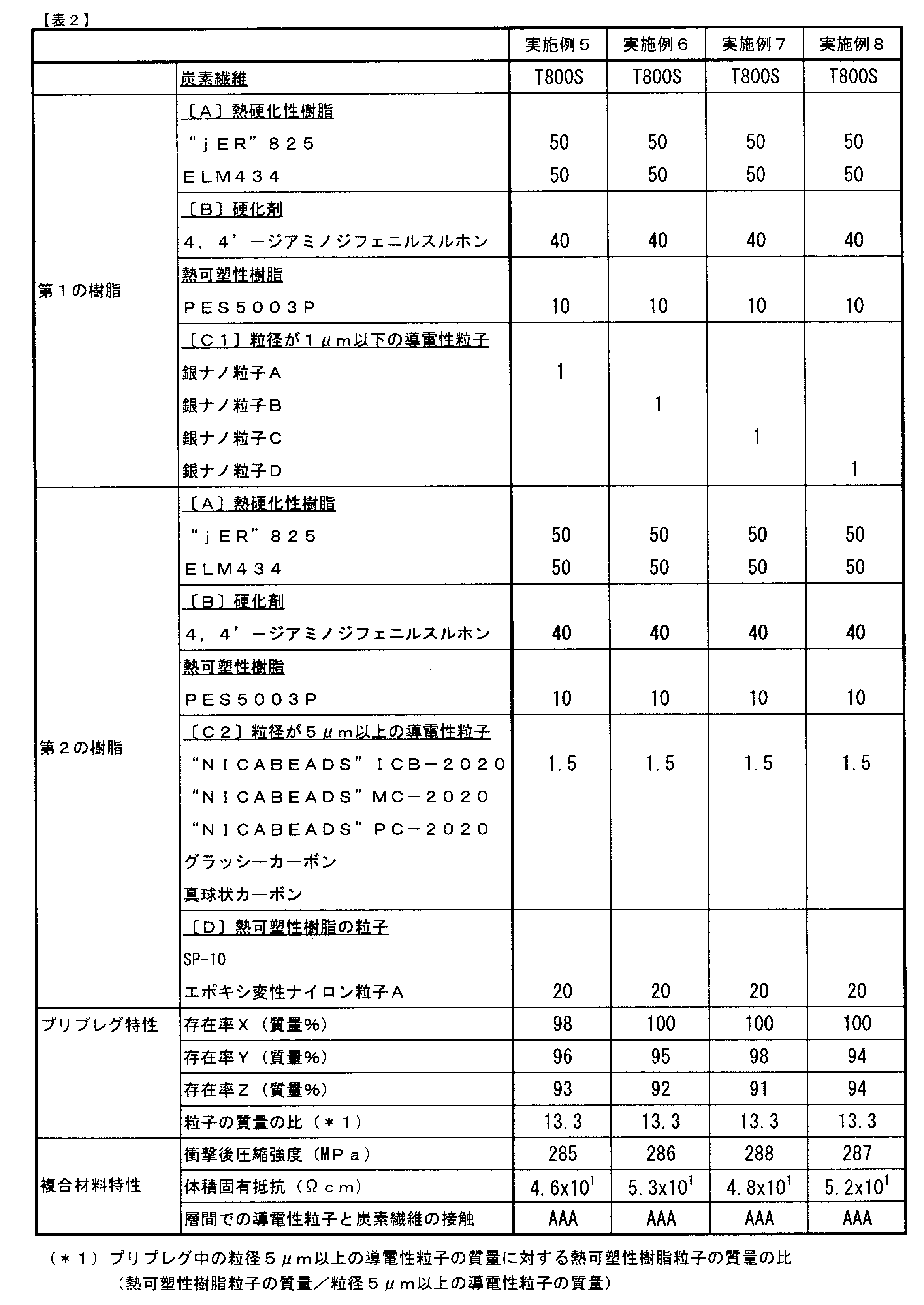


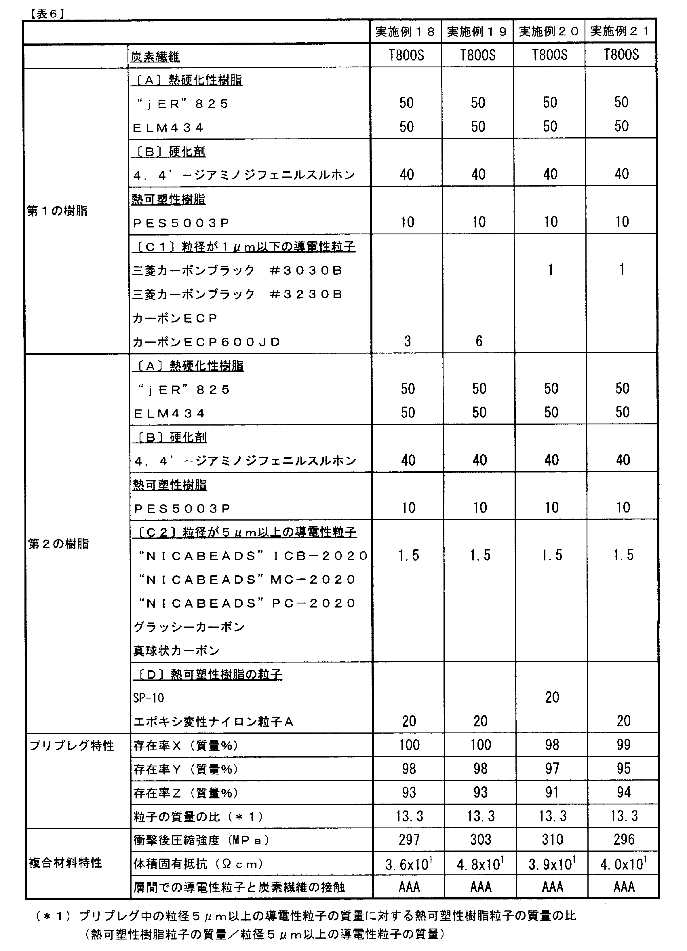


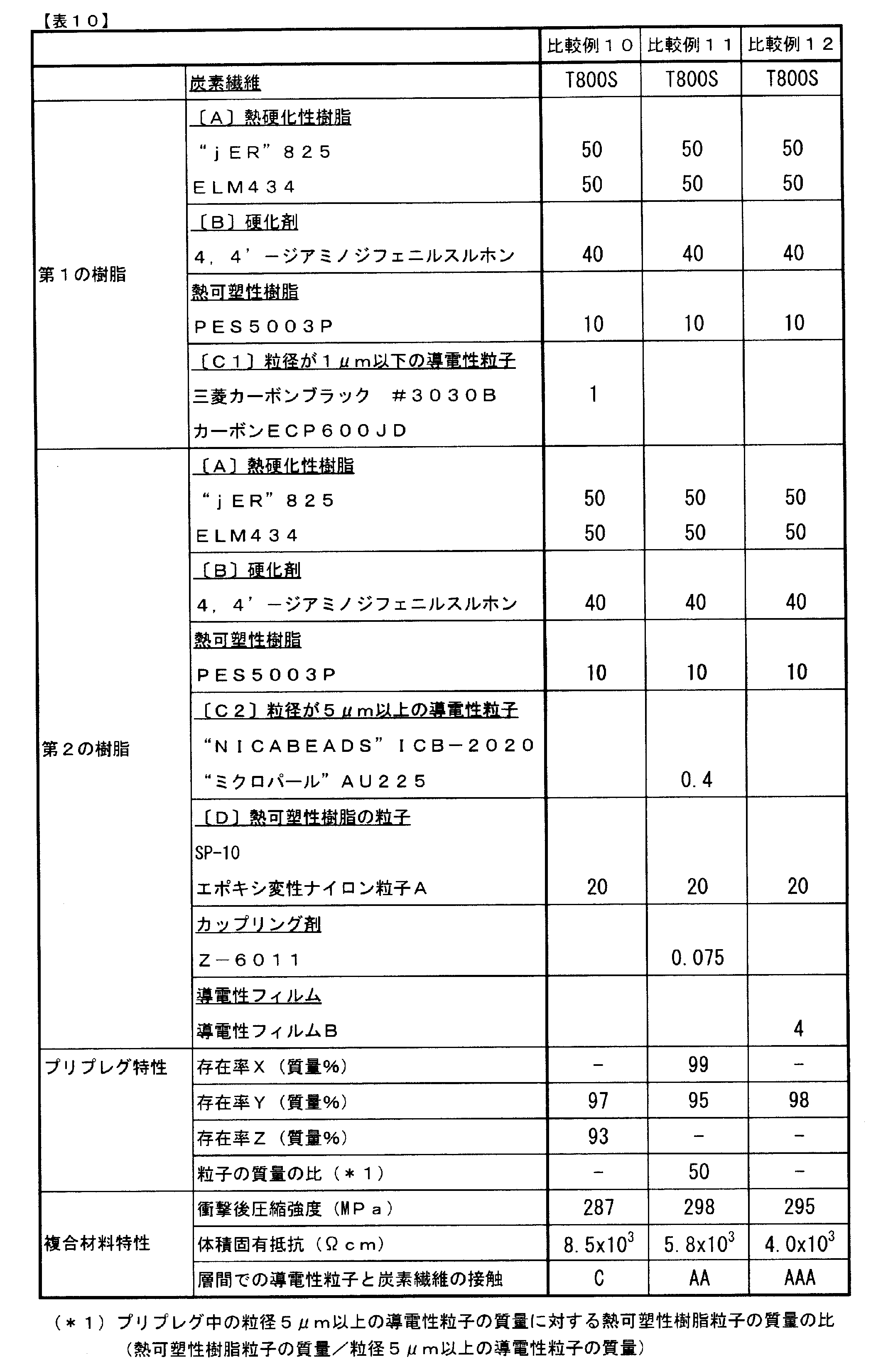
表1~6に示すように、実施例で製作したプリプレグはいずれも、粒子の存在率X、Yは、それぞれ90質量%を超えていた。すなわち、粒径5μm以上の導電性粒子および熱可塑性樹脂の粒子が、プリプレグの厚さ方向において、プリプレグの表層に偏って分布していた。また、粒子の存在率Zは90質量%を超えていた。すなわち、粒径1μm以下の導電性粒子のうち90質量%が、プリプレグの厚さ方向において、プリプレグの両方の主面のそれぞれに最も近い位置にある炭素繊維よりも内側に分布していることが確認された。
以上の実験結果から明らかなように、粒径が1μm以下の第1の導電性粒子(C1)を含む第1の樹脂、および粒径が5μm以上の第2の導電性粒子(C2)を含む第2の樹脂を用いて作製した各実施例のプリプレグによれば、高い導電性を有する炭素繊維複合材料を製造することができる。さらには、第2の導電性粒子(C2)と熱可塑性樹脂の粒子との相乗的な効果により、優れた耐衝撃性が達成されることが確認された。
1:炭素繊維
3:熱硬化性樹脂組成物
5:マトリックス樹脂
10:炭素繊維層
21:第1の導電性粒子(粒径1μm以下の導電性粒子)
22:第2の導電性粒子(粒径5μm以上の導電性粒子)
30:熱可塑性樹脂の粒子
50:層間形成層
100:プリプレグ
S1,S2:プリプレグの主面
3:熱硬化性樹脂組成物
5:マトリックス樹脂
10:炭素繊維層
21:第1の導電性粒子(粒径1μm以下の導電性粒子)
22:第2の導電性粒子(粒径5μm以上の導電性粒子)
30:熱可塑性樹脂の粒子
50:層間形成層
100:プリプレグ
S1,S2:プリプレグの主面
Claims (11)
- 複数の炭素繊維と、この複数の炭素繊維に含浸しているマトリックス樹脂と、を有するシート状のプリプレグにおいて、
前記マトリックス樹脂が、熱硬化性樹脂、硬化剤、導電性粒子および熱可塑性樹脂の粒子を含有し、
前記導電性粒子が、粒径1μm以下の導電性粒子と、粒径5μm以上の導電性粒子と、を含み、
前記粒径5μm以上の導電性粒子および前記熱可塑性樹脂の粒子が、前記プリプレグの厚さ方向において、このプリプレグの片方又は両方の表層に偏って分布しており、
前記粒径1μm以下の導電性粒子が、前記プリプレグの厚さ方向において、このプリプレグの両方の主面のそれぞれに最も近い位置にある前記炭素繊維よりも内側に偏って分布している、プリプレグ。 - 前記プリプレグ中に含まれる前記粒径1μm以下の導電性粒子のうちの90~100質量%が、このプリプレグの厚さ方向において、このプリプレグの両方の主面のそれぞれに最も近い位置にある前記炭素繊維よりも内側に存在している、請求項1のプリプレグ。
- 前記プリプレグ中に含まれる前記粒径5μm以上の導電性粒子のうちの90~100質量%および前記熱可塑性樹脂の粒子のうちの90~100質量%が、このプリプレグの厚さ方向において、このプリプレグの両方の主面のそれぞれからこのプリプレグの厚さに対して20%の深さまでの範囲内に存在している、請求項1又は2のプリプレグ。
- 前記プリプレグ中に含まれる前記粒径5μm以上の導電性粒子のうちの90~100質量%および前記熱可塑性樹脂の粒子のうちの90~100質量%が、このプリプレグの厚さ方向において、このプリプレグの片方の主面からこのプリプレグの厚さに対して20%の深さまでの範囲内に存在している、請求項1又は2のプリプレグ。
- 前記導電性粒子が、カーボン粒子、および、無機材料又は有機材料の核粒子とこの核粒子を被覆する導電層とを有する複合粒子からなる群から選ばれる少なくとも1種である、請求項1~4のいずれかのプリプレグ。
- 前記プリプレグ中の前記粒径5μm以上の導電性粒子の質量に対する前記熱可塑性樹脂の粒子の質量の比が1~1000である、請求項1~5のいずれかのプリプレグ。
- 複数の炭素繊維と、この複数の炭素繊維に含浸しており熱硬化性樹脂、硬化剤および粒径が1μm以下の第1の導電性粒子を含有する第1の樹脂と、を有するシート状の一次プリプレグの片面上又は両面上に、熱硬化性樹脂、硬化剤、粒径が5μm以上の第2の導電性粒子および熱可塑性樹脂の粒子を含有する第2の樹脂の層を設ける工程を備える、プリプレグの製造方法。
- 前記第2の樹脂に含まれる前記第2の導電性粒子の比率が、前記第2の樹脂の質量に対して0.01~50質量%である、請求項7のプリプレグの製造方法。
- 前記第2の導電性粒子の平均粒径が100μm未満である、請求項7又は8の製造方法。
- 2枚以上のプリプレグを含む積層体を加熱および加圧する工程を備える方法により得ることのできる炭素繊維強化複合材料であって、
前記積層体の中の少なくとも2枚以上のプリプレグが、請求項1~6のいずれかのプリプレグまたは請求項7~9のいずれかの方法により得ることのできるプリプレグであり、これら請求項1~6のいずれかのプリプレグまたは請求項7~9のいずれかの方法により得ることのできるプリプレグのうちの少なくとも2枚が隣接している、炭素繊維強化複合材料。 - 前記隣接する2枚のプリプレグの境界面を挟んで隣り合っていた前記炭素繊維と炭素繊維との間に存在する前記粒径5μmの導電性粒子のうち、その30%以上の個数が、前記両方の炭素繊維と接触している、請求項10の炭素繊維強化複合材料。
Priority Applications (3)
| Application Number | Priority Date | Filing Date | Title |
|---|---|---|---|
| EP12757515.7A EP2687557B1 (en) | 2011-03-17 | 2012-02-24 | Prepreg, method of manufacturing prepreg, and carbon fiber-reinforced composite material |
| US14/003,916 US9481145B2 (en) | 2011-03-17 | 2012-02-24 | Prepreg, method of manufacturing prepreg, and carbon fiber-reinforced composite material |
| JP2012511851A JP5900327B2 (ja) | 2011-03-17 | 2012-02-24 | プリプレグ、プリプレグの製造方法および炭素繊維強化複合材料の製造方法 |
Applications Claiming Priority (2)
| Application Number | Priority Date | Filing Date | Title |
|---|---|---|---|
| JP2011058793 | 2011-03-17 | ||
| JP2011-058793 | 2011-03-17 |
Publications (1)
| Publication Number | Publication Date |
|---|---|
| WO2012124450A1 true WO2012124450A1 (ja) | 2012-09-20 |
Family
ID=46830526
Family Applications (1)
| Application Number | Title | Priority Date | Filing Date |
|---|---|---|---|
| PCT/JP2012/054522 WO2012124450A1 (ja) | 2011-03-17 | 2012-02-24 | プリプレグ、プリプレグの製造方法および炭素繊維強化複合材料 |
Country Status (4)
| Country | Link |
|---|---|
| US (1) | US9481145B2 (ja) |
| EP (1) | EP2687557B1 (ja) |
| JP (1) | JP5900327B2 (ja) |
| WO (1) | WO2012124450A1 (ja) |
Cited By (21)
| Publication number | Priority date | Publication date | Assignee | Title |
|---|---|---|---|---|
| WO2013146229A1 (ja) * | 2012-03-27 | 2013-10-03 | 三菱重工業株式会社 | 構造体用構造材 |
| JP2014195990A (ja) * | 2013-02-10 | 2014-10-16 | ザ・ボーイング・カンパニーTheBoeing Company | 発熱体として使用される金属マトリックス複合材 |
| JP2015107651A (ja) * | 2012-09-26 | 2015-06-11 | 東邦テナックス株式会社 | プリプレグ及びその製造方法 |
| CN104884512A (zh) * | 2012-12-27 | 2015-09-02 | 东丽株式会社 | 传导性纤维增强聚合物复合体及多功能复合体 |
| WO2015146781A1 (ja) * | 2014-03-24 | 2015-10-01 | 東レ株式会社 | プリプレグおよび繊維強化複合材料 |
| JP2015190575A (ja) * | 2014-03-28 | 2015-11-02 | 住友理工株式会社 | 導電性シャフトおよびそれを用いたoa機器用導電性ロール、並びに導電性シャフトの製法 |
| US9187606B2 (en) | 2010-03-17 | 2015-11-17 | Hexcel Composites Limited | Process for manufacturing composite materials |
| US20160326323A1 (en) * | 2014-01-10 | 2016-11-10 | Komatsu Seiren Co., Ltd. | Fiber-reinforced resin material and molded fiber-reinforced resin body obtained using the same |
| JP2016222873A (ja) * | 2015-06-03 | 2016-12-28 | 三菱重工業株式会社 | 樹脂複合材料、その硬化方法、および樹脂成形品 |
| JP2017501904A (ja) * | 2013-12-13 | 2017-01-19 | サイテック インダストリーズ インコーポレイテッド | 導電特性及び耐層間剥離特性を有する複合材料 |
| JP2017190379A (ja) * | 2016-04-12 | 2017-10-19 | 東邦テナックス株式会社 | プリプレグ、強化繊維、繊維強化複合材料、およびプリプレグの製造方法 |
| EP3042926B1 (en) * | 2013-09-06 | 2019-07-03 | Daicel-Evonik Ltd. | Molded article comprising a fiber-reinforced resin and method for producing same |
| JP2019178299A (ja) * | 2018-03-30 | 2019-10-17 | 三菱ケミカル株式会社 | 導電性プリプレグ、これを用いた複合材及び複合材積層体 |
| JPWO2019098243A1 (ja) * | 2017-11-14 | 2020-10-01 | 東レ株式会社 | プリプレグおよび繊維強化複合材料 |
| WO2020235489A1 (ja) * | 2019-05-23 | 2020-11-26 | 東レ株式会社 | プリプレグ、積層体および成形品 |
| WO2021131740A1 (ja) | 2019-12-26 | 2021-07-01 | 東レ株式会社 | プリプレグ |
| WO2022004586A1 (ja) | 2020-06-30 | 2022-01-06 | 東レ株式会社 | 繊維強化複合材料およびプリプレグの製造方法 |
| WO2022209454A1 (ja) * | 2021-03-30 | 2022-10-06 | 東レ株式会社 | 扁平軽量部材およびその製造方法 |
| WO2022230800A1 (ja) | 2021-04-26 | 2022-11-03 | 東レ株式会社 | プリプレグ |
| WO2023074733A1 (ja) | 2021-10-27 | 2023-05-04 | 東レ株式会社 | 炭素繊維強化複合材料 |
| WO2023190319A1 (ja) * | 2022-03-30 | 2023-10-05 | 東レ株式会社 | 炭素繊維強化複合材料およびプリプレグ |
Families Citing this family (12)
| Publication number | Priority date | Publication date | Assignee | Title |
|---|---|---|---|---|
| GB201307898D0 (en) * | 2012-06-14 | 2013-06-12 | Hexcel Composites Ltd | Improvements in composite materials |
| US9290212B2 (en) * | 2013-05-24 | 2016-03-22 | Ford Global Technologies, Llc | Carbon fiber prepreg-wrapped beam structures |
| DE112015003073T5 (de) * | 2014-06-30 | 2017-03-30 | Yazaki Corporation | Mehrfachkabel |
| US10337490B2 (en) | 2015-06-29 | 2019-07-02 | General Electric Company | Structural component for a modular rotor blade |
| US9897065B2 (en) | 2015-06-29 | 2018-02-20 | General Electric Company | Modular wind turbine rotor blades and methods of assembling same |
| CA3020078C (en) * | 2016-06-28 | 2024-01-16 | Toray Industries, Inc. | Prepreg and production method therefor |
| EP3595853A4 (en) | 2017-03-16 | 2020-12-23 | Guerrilla Industries LLC | COMPOSITE STRUCTURES AND PROCESSES FOR FORMING COMPOSITE STRUCTURES |
| US11820858B2 (en) | 2017-12-01 | 2023-11-21 | Teijin Limited | Prepreg, method for producing same, and method for producing fiber-reinforced composite material |
| CN111518300B (zh) * | 2020-05-15 | 2023-05-30 | 郑州仿弦新材料科技有限公司 | 一种碳纤维预浸料的制备工艺 |
| EP4304841A1 (en) | 2021-03-09 | 2024-01-17 | Guerrilla Industries LLC | Composite structures and methods of forming composite structures |
| CN114015095B (zh) * | 2021-11-25 | 2024-01-16 | 中国人民解放军国防科技大学 | 一种表层富含金属颗粒的连续纤维增强环氧树脂预浸料及其制备方法 |
| CN115284710A (zh) * | 2022-07-06 | 2022-11-04 | 中国人民解放军国防科技大学 | 金属颗粒夹层纤维增强树脂基复合材料及其制备方法 |
Citations (8)
| Publication number | Priority date | Publication date | Assignee | Title |
|---|---|---|---|---|
| JPH0326750A (ja) | 1989-06-23 | 1991-02-05 | Sumitomo Chem Co Ltd | 繊維強化複合材料 |
| JPH03124407A (ja) * | 1989-10-06 | 1991-05-28 | Osaka Gas Co Ltd | 高導電性炭素繊維構造体の製造方法 |
| US5028478A (en) | 1986-12-25 | 1991-07-02 | Troy Industries, Inc. | Fiber reinforced composite materials having resin practice inter-layer zones |
| JP2005314586A (ja) * | 2004-04-30 | 2005-11-10 | Idemitsu Kosan Co Ltd | 梁構造を有する射出成形体及びその製造方法 |
| JP2008231395A (ja) | 2006-08-07 | 2008-10-02 | Toray Ind Inc | プリプレグおよび炭素繊維強化複合材料 |
| JP2009062473A (ja) | 2007-09-07 | 2009-03-26 | Toray Ind Inc | プリプレグおよび炭素繊維強化複合材料 |
| JP2010053224A (ja) * | 2008-08-27 | 2010-03-11 | Kyocera Chemical Corp | 熱伝導性樹脂シート、熱伝導板、熱伝導性プリント配線板及び放熱部材 |
| JP2010508416A (ja) | 2006-11-06 | 2010-03-18 | ヘクセル コンポジット、リミテッド | 改良型複合材料 |
Family Cites Families (3)
| Publication number | Priority date | Publication date | Assignee | Title |
|---|---|---|---|---|
| US5025045A (en) * | 1987-12-24 | 1991-06-18 | Hercules Incorporated | Damage tolerant composites containing infusible particles |
| GB2473226A (en) * | 2009-09-04 | 2011-03-09 | Hexcel Composites Ltd | Composite materials |
| US10102939B2 (en) * | 2013-01-28 | 2018-10-16 | The Boeing Company | Conductive fiber reinforced polymer composition |
-
2012
- 2012-02-24 EP EP12757515.7A patent/EP2687557B1/en not_active Not-in-force
- 2012-02-24 US US14/003,916 patent/US9481145B2/en active Active
- 2012-02-24 WO PCT/JP2012/054522 patent/WO2012124450A1/ja active Application Filing
- 2012-02-24 JP JP2012511851A patent/JP5900327B2/ja not_active Expired - Fee Related
Patent Citations (8)
| Publication number | Priority date | Publication date | Assignee | Title |
|---|---|---|---|---|
| US5028478A (en) | 1986-12-25 | 1991-07-02 | Troy Industries, Inc. | Fiber reinforced composite materials having resin practice inter-layer zones |
| JPH0326750A (ja) | 1989-06-23 | 1991-02-05 | Sumitomo Chem Co Ltd | 繊維強化複合材料 |
| JPH03124407A (ja) * | 1989-10-06 | 1991-05-28 | Osaka Gas Co Ltd | 高導電性炭素繊維構造体の製造方法 |
| JP2005314586A (ja) * | 2004-04-30 | 2005-11-10 | Idemitsu Kosan Co Ltd | 梁構造を有する射出成形体及びその製造方法 |
| JP2008231395A (ja) | 2006-08-07 | 2008-10-02 | Toray Ind Inc | プリプレグおよび炭素繊維強化複合材料 |
| JP2010508416A (ja) | 2006-11-06 | 2010-03-18 | ヘクセル コンポジット、リミテッド | 改良型複合材料 |
| JP2009062473A (ja) | 2007-09-07 | 2009-03-26 | Toray Ind Inc | プリプレグおよび炭素繊維強化複合材料 |
| JP2010053224A (ja) * | 2008-08-27 | 2010-03-11 | Kyocera Chemical Corp | 熱伝導性樹脂シート、熱伝導板、熱伝導性プリント配線板及び放熱部材 |
Cited By (40)
| Publication number | Priority date | Publication date | Assignee | Title |
|---|---|---|---|---|
| US10144153B2 (en) | 2010-03-17 | 2018-12-04 | Hexcel Composites Limited | Process for manufacturing composite materials |
| US9187606B2 (en) | 2010-03-17 | 2015-11-17 | Hexcel Composites Limited | Process for manufacturing composite materials |
| WO2013146229A1 (ja) * | 2012-03-27 | 2013-10-03 | 三菱重工業株式会社 | 構造体用構造材 |
| JPWO2013146229A1 (ja) * | 2012-03-27 | 2015-12-10 | 三菱重工業株式会社 | 構造体用構造材 |
| US10927226B2 (en) | 2012-09-26 | 2021-02-23 | Toho Tenax Co., Ltd. | Prepreg and method for producing same |
| JP2015107651A (ja) * | 2012-09-26 | 2015-06-11 | 東邦テナックス株式会社 | プリプレグ及びその製造方法 |
| EP2902435A4 (en) * | 2012-09-26 | 2016-05-11 | Toho Tenax Co Ltd | PREPREG AND METHOD FOR THE PRODUCTION THEREOF |
| JP2016094608A (ja) * | 2012-09-26 | 2016-05-26 | 東邦テナックス株式会社 | プリプレグ及びその製造方法 |
| US20150299408A1 (en) * | 2012-12-27 | 2015-10-22 | Toray Industries, Inc. | Conductive fiber reinforced polymer composite and multifunctional composite |
| CN104884512A (zh) * | 2012-12-27 | 2015-09-02 | 东丽株式会社 | 传导性纤维增强聚合物复合体及多功能复合体 |
| EP2938659A4 (en) * | 2012-12-27 | 2016-10-12 | Toray Industries | CONDUCTIVE FIBER-REINFORCED POLYMER COMPOSITE AND MULTIFUNCTION COMPOSITE |
| CN104884512B (zh) * | 2012-12-27 | 2018-11-06 | 东丽株式会社 | 传导性纤维增强聚合物复合体及多功能复合体 |
| JP2014195990A (ja) * | 2013-02-10 | 2014-10-16 | ザ・ボーイング・カンパニーTheBoeing Company | 発熱体として使用される金属マトリックス複合材 |
| EP3042926B1 (en) * | 2013-09-06 | 2019-07-03 | Daicel-Evonik Ltd. | Molded article comprising a fiber-reinforced resin and method for producing same |
| JP2017501904A (ja) * | 2013-12-13 | 2017-01-19 | サイテック インダストリーズ インコーポレイテッド | 導電特性及び耐層間剥離特性を有する複合材料 |
| US10961360B2 (en) * | 2014-01-10 | 2021-03-30 | Komatsu Matere Co., Ltd. | Fiber-reinforced resin material and molded fiber-reinforced resin body obtained using the same |
| US20160326323A1 (en) * | 2014-01-10 | 2016-11-10 | Komatsu Seiren Co., Ltd. | Fiber-reinforced resin material and molded fiber-reinforced resin body obtained using the same |
| US10597503B2 (en) | 2014-03-24 | 2020-03-24 | Toray Industries, Inc. | Prepreg and fiber reinforced composite material |
| KR101741387B1 (ko) | 2014-03-24 | 2017-05-29 | 도레이 카부시키가이샤 | 프리프레그 및 섬유 강화 복합 재료 |
| CN106133036B (zh) * | 2014-03-24 | 2018-05-01 | 东丽株式会社 | 预浸料坯及纤维增强复合材料 |
| CN106133036A (zh) * | 2014-03-24 | 2016-11-16 | 东丽株式会社 | 预浸料坯及纤维增强复合材料 |
| JP5831668B1 (ja) * | 2014-03-24 | 2015-12-09 | 東レ株式会社 | プリプレグおよび繊維強化複合材料 |
| EP3093308A4 (en) * | 2014-03-24 | 2017-01-18 | Toray Industries, Inc. | Prepreg and fiber-reinforced composite material |
| WO2015146781A1 (ja) * | 2014-03-24 | 2015-10-01 | 東レ株式会社 | プリプレグおよび繊維強化複合材料 |
| JP2015190575A (ja) * | 2014-03-28 | 2015-11-02 | 住友理工株式会社 | 導電性シャフトおよびそれを用いたoa機器用導電性ロール、並びに導電性シャフトの製法 |
| JP2016222873A (ja) * | 2015-06-03 | 2016-12-28 | 三菱重工業株式会社 | 樹脂複合材料、その硬化方法、および樹脂成形品 |
| JP2017190379A (ja) * | 2016-04-12 | 2017-10-19 | 東邦テナックス株式会社 | プリプレグ、強化繊維、繊維強化複合材料、およびプリプレグの製造方法 |
| JP7183793B2 (ja) | 2017-11-14 | 2022-12-06 | 東レ株式会社 | プリプレグおよび繊維強化複合材料 |
| JPWO2019098243A1 (ja) * | 2017-11-14 | 2020-10-01 | 東レ株式会社 | プリプレグおよび繊維強化複合材料 |
| JP7124390B2 (ja) | 2018-03-30 | 2022-08-24 | 三菱ケミカル株式会社 | 導電性プリプレグ、これを用いた複合材及び複合材積層体 |
| JP2019178299A (ja) * | 2018-03-30 | 2019-10-17 | 三菱ケミカル株式会社 | 導電性プリプレグ、これを用いた複合材及び複合材積層体 |
| JPWO2020235489A1 (ja) * | 2019-05-23 | 2020-11-26 | ||
| JP7047923B2 (ja) | 2019-05-23 | 2022-04-05 | 東レ株式会社 | プリプレグ、積層体および成形品 |
| WO2020235489A1 (ja) * | 2019-05-23 | 2020-11-26 | 東レ株式会社 | プリプレグ、積層体および成形品 |
| WO2021131740A1 (ja) | 2019-12-26 | 2021-07-01 | 東レ株式会社 | プリプレグ |
| WO2022004586A1 (ja) | 2020-06-30 | 2022-01-06 | 東レ株式会社 | 繊維強化複合材料およびプリプレグの製造方法 |
| WO2022209454A1 (ja) * | 2021-03-30 | 2022-10-06 | 東レ株式会社 | 扁平軽量部材およびその製造方法 |
| WO2022230800A1 (ja) | 2021-04-26 | 2022-11-03 | 東レ株式会社 | プリプレグ |
| WO2023074733A1 (ja) | 2021-10-27 | 2023-05-04 | 東レ株式会社 | 炭素繊維強化複合材料 |
| WO2023190319A1 (ja) * | 2022-03-30 | 2023-10-05 | 東レ株式会社 | 炭素繊維強化複合材料およびプリプレグ |
Also Published As
| Publication number | Publication date |
|---|---|
| US9481145B2 (en) | 2016-11-01 |
| JP5900327B2 (ja) | 2016-04-06 |
| JPWO2012124450A1 (ja) | 2014-07-17 |
| EP2687557B1 (en) | 2018-12-05 |
| US20130344305A1 (en) | 2013-12-26 |
| EP2687557A1 (en) | 2014-01-22 |
| EP2687557A4 (en) | 2014-12-03 |
Similar Documents
| Publication | Publication Date | Title |
|---|---|---|
| JP5900327B2 (ja) | プリプレグ、プリプレグの製造方法および炭素繊維強化複合材料の製造方法 | |
| JP5541394B2 (ja) | プリプレグおよび炭素繊維強化複合材料 | |
| AU2013356422B2 (en) | Conductive surfacing material for composite structures | |
| EP2902435A1 (en) | Prepreg and method for producing same | |
| JP2011231331A5 (ja) | ||
| JP6210007B2 (ja) | プリプレグおよびその製造方法、ならびに炭素繊維強化複合材料 | |
| WO2011027160A1 (en) | Improvements in composite materials | |
| WO2018003694A1 (ja) | プリプレグおよびその製造方法 | |
| JP6519492B2 (ja) | プリプレグおよび繊維強化複合材料 | |
| JP2011213991A (ja) | 炭素繊維強化複合材料 | |
| JPWO2015146781A1 (ja) | プリプレグおよび繊維強化複合材料 | |
| JP6213225B2 (ja) | プリプレグおよび繊維強化複合材料 | |
| JP2009062473A (ja) | プリプレグおよび炭素繊維強化複合材料 | |
| WO2022004586A1 (ja) | 繊維強化複合材料およびプリプレグの製造方法 | |
| JP6308146B2 (ja) | 樹脂フィルムおよびその製造方法 | |
| WO2023190319A1 (ja) | 炭素繊維強化複合材料およびプリプレグ |
Legal Events
| Date | Code | Title | Description |
|---|---|---|---|
| ENP | Entry into the national phase |
Ref document number: 2012511851 Country of ref document: JP Kind code of ref document: A |
|
| 121 | Ep: the epo has been informed by wipo that ep was designated in this application |
Ref document number: 12757515 Country of ref document: EP Kind code of ref document: A1 |
|
| WWE | Wipo information: entry into national phase |
Ref document number: 14003916 Country of ref document: US |
|
| NENP | Non-entry into the national phase |
Ref country code: DE |