WO2012124174A1 - Relais électromagnétique - Google Patents
Relais électromagnétique Download PDFInfo
- Publication number
- WO2012124174A1 WO2012124174A1 PCT/JP2011/057282 JP2011057282W WO2012124174A1 WO 2012124174 A1 WO2012124174 A1 WO 2012124174A1 JP 2011057282 W JP2011057282 W JP 2011057282W WO 2012124174 A1 WO2012124174 A1 WO 2012124174A1
- Authority
- WO
- WIPO (PCT)
- Prior art keywords
- contact
- terminal
- electromagnetic relay
- press
- base
- Prior art date
Links
Images


Classifications
-
- H—ELECTRICITY
- H01—ELECTRIC ELEMENTS
- H01H—ELECTRIC SWITCHES; RELAYS; SELECTORS; EMERGENCY PROTECTIVE DEVICES
- H01H9/00—Details of switching devices, not covered by groups H01H1/00 - H01H7/00
- H01H9/30—Means for extinguishing or preventing arc between current-carrying parts
- H01H9/44—Means for extinguishing or preventing arc between current-carrying parts using blow-out magnet
-
- H—ELECTRICITY
- H01—ELECTRIC ELEMENTS
- H01H—ELECTRIC SWITCHES; RELAYS; SELECTORS; EMERGENCY PROTECTIVE DEVICES
- H01H50/00—Details of electromagnetic relays
- H01H50/02—Bases; Casings; Covers
- H01H50/04—Mounting complete relay or separate parts of relay on a base or inside a case
-
- H—ELECTRICITY
- H01—ELECTRIC ELEMENTS
- H01H—ELECTRIC SWITCHES; RELAYS; SELECTORS; EMERGENCY PROTECTIVE DEVICES
- H01H50/00—Details of electromagnetic relays
- H01H50/16—Magnetic circuit arrangements
- H01H50/18—Movable parts of magnetic circuits, e.g. armature
- H01H50/24—Parts rotatable or rockable outside coil
-
- H—ELECTRICITY
- H01—ELECTRIC ELEMENTS
- H01H—ELECTRIC SWITCHES; RELAYS; SELECTORS; EMERGENCY PROTECTIVE DEVICES
- H01H50/00—Details of electromagnetic relays
- H01H50/16—Magnetic circuit arrangements
- H01H50/18—Movable parts of magnetic circuits, e.g. armature
- H01H50/30—Mechanical arrangements for preventing or damping vibration or shock, e.g. by balancing of armature
-
- H—ELECTRICITY
- H01—ELECTRIC ELEMENTS
- H01H—ELECTRIC SWITCHES; RELAYS; SELECTORS; EMERGENCY PROTECTIVE DEVICES
- H01H9/00—Details of switching devices, not covered by groups H01H1/00 - H01H7/00
- H01H9/30—Means for extinguishing or preventing arc between current-carrying parts
- H01H9/44—Means for extinguishing or preventing arc between current-carrying parts using blow-out magnet
- H01H9/443—Means for extinguishing or preventing arc between current-carrying parts using blow-out magnet using permanent magnets
Definitions
- the present invention relates to an electromagnetic relay.
- an electromagnetic block formed by winding a coil around an iron core via a spool is excited and demagnetized to rotate a movable iron piece that is rotatably supported by a yoke crimped to the iron core.
- a movable contact is opened and closed with a fixed contact of a fixed contact piece arranged opposite to the contact piece by driving the contact piece (see, for example, Patent Document 1).
- a permanent magnet is arranged above the contact opening / closing part and a magnetic field is generated between the contacts. The arc is extinguished early.
- an object of the present invention is to provide an electromagnetic relay having a small and inexpensive arc extinguishing function that can extinguish an arc generated when a contact is opened and closed at an early stage.
- Electromagnetic relay A contact opening / closing portion having a contact set consisting of a pair of contacts that can be contacted and separated;
- Arc extinguishing composed of a connecting member formed by connecting opposing walls arranged in a direction perpendicular to the contact / separation direction of the contact via an intermediate portion, and a permanent magnet arranged in an opposing part of the opposing wall A member, It is set as the structure provided with.
- the magnetic field generated from the permanent magnet forms a closed loop through a connecting member having a higher magnetic permeability than the surrounding atmosphere. Therefore, the magnetic flux can be concentrated at the contact opening / closing position. As a result, the influence of the magnetic field by the arc extinguishing member can be sufficiently applied to the arc current generated when the contact is opened and closed, and the arc current can be sufficiently extended upward to extinguish the arc early. it can.
- the arc extinguishing member can be completely insulated from the contact opening / closing portion and the electromagnet block which are internal components.
- the polarity of the opposing surface of each permanent magnet and the direction in which the arc current generated when the contacts are opened and closed are determined so that the arc current can generate a force that shifts toward the intermediate portion of the connecting member. Is preferred.
- This configuration makes it possible to extinguish arcs by deforming the arc current to a position where the arc current is most unlikely to be adversely affected.
- the contact opening / closing unit includes a pair of movable contact pieces and a pair of fixed contact pieces provided with fixed contacts that face each other so that the movable contacts of the movable contact pieces can come in contact with and separate from each other. It is preferable that a connection terminal for electrically connecting one of the movable contact pieces and one of the fixed contact pieces is provided.
- the base block includes a first base portion having the contact pieces and the electromagnet block, and a second base having tab terminals respectively connected to the contact pieces and coil terminals of the electromagnet block. preferable.
- connection position can be freely set by the tab terminal even if the part composed of other parts is an existing one by simply adding the second base part.
- connection member is arranged around the contact opening / closing position, and the permanent magnet is arranged at the opposite portion, so that the magnetic field generated from the permanent magnet is effectively concentrated on the contact opening / closing position. be able to. For this reason, even if an arc current is generated when the contact is opened and closed, the arc current can be deformed upward by a magnetic field and extinguished quickly.
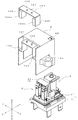
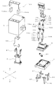
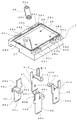
- FIG. 2 is an exploded perspective view of FIG. 1.
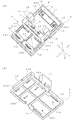
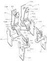
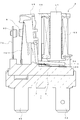
- A) is a perspective view which shows the state which looked at the 1st base part from the upper side
- (b) is a perspective view which shows the state which looked at the 1st base part from the lower side. It is a disassembled perspective view of a 2nd base part and a tab terminal. It is a perspective view which shows the state which looked at FIG. 6 from the downward side.
- FIG. 9 It is a perspective view which shows the connection state of a movable contact piece, a fixed contact piece, a coil terminal, a connection terminal, and a tab terminal. It is a disassembled perspective view of the electromagnet block and movable iron piece shown in FIG. It is a perspective view which shows the state which looked at FIG. 9 from the other side. It is a fragmentary perspective view which shows the relationship between the force which acts on an arc current, the direction of a magnetic field, and an arc current. It is sectional drawing at the time of contact closing which shows the state which removed the case from FIG. It is sectional drawing at the time of contact opening which shows the state which removed the case from FIG.
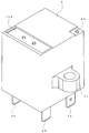
- This electromagnetic relay is generally a base block 1 provided with an electromagnet block 2, a contact opening / closing part 3, and a movable iron piece 4 and covered with a case 5.
- the base block 1 includes a first base portion 6 and a second base portion 7. (Hereinafter, the direction extending in the longitudinal direction along the long side will be described as the X axis, the direction extending in the short direction along the short side as the Y axis, and the direction extending in the height direction as the Z axis).
- the first base portion 6 is formed into a rectangular shape in plan view by molding a synthetic resin material.
- the first mounting portion is provided at two locations in the longitudinal direction (XX ′ direction). 8 and the second mounting portion 9 are juxtaposed.
- the first mounting portion 8 is for mounting an electromagnet block 2 to be described later, and is formed with a pedestal portion 10 bulging upward except for the peripheral edge portion.
- a recess 11 extending in the short direction (YY ′ direction) is formed on one end side (X direction side) of the pedestal portion 10.
- Positioning recesses 12 that are deeper are formed at both ends of the recess 11.
- a guide protrusion 66 formed on a spool 52 of the electromagnet block 2 described later is positioned in the positioning recess 12.
- a through hole 29 a through which the connection terminal portion 70 of the coil terminal 67 is inserted is formed on the bottom surface of the positioning recess 12.
- Coil terminal holes 13 extending in the longitudinal direction (XX ′ direction) and penetrating through the upper and lower surfaces are formed on both sides of the recess 11 (near the outside of each positioning recess 12).
- a guide portion 14 is formed at a central portion of the first base portion 6 at a boundary portion with the second mounting portion 9.
- the guide portion 14 is composed of a pair of guide walls 15 provided to face in the short direction (YY ′ direction) and an insulating wall 16 connecting them.
- a guide groove 17 extending in the vertical direction is formed on the opposing surface of the guide wall 15. Both guide grooves 17 guide both side portions of a yoke 55 described later.
- a pair of protrusions 18 and recesses 19 are formed in the region surrounded by the guide wall 15 and the insulating wall 16 at a predetermined interval in the lateral direction (YY ′ direction). The hinge spring is guided by the protrusion 18 and the recess 19.
- the second mounting portion 9 is for mounting the contact opening / closing portion 3 and is formed with recesses 21a and 21b that are partitioned in the short direction (YY ′ direction) by the ridge portion 20, respectively.
- recesses 21a and 21b slit-shaped first terminal holes 22a and 22b are formed along the guide wall 15 so as to open on the upper and lower surfaces, respectively.
- a movable contact piece 79 described later is press-fitted into each first terminal hole 22a, 22b.
- the second mounting portion 9 has a thick portion 23 on one end side (X ′ direction side).
- the thick portion 23 is provided with a groove 23a extending in the longitudinal direction (XX ′ direction) in the central portion, and each of the two divided portions has a slit-like second terminal hole 24a along the short direction (YY ′ direction). , 24b are formed so as to open on the upper and lower surfaces, respectively.
- a fixed contact piece 78 described later is press-fitted and fixed in each of the second terminal holes 24a and 24b.
- the second base portion 7 is formed in a rectangular shape in plan view by molding a synthetic resin material in the same manner as the first base portion 6.
- a rectangular recess 26 surrounded by the peripheral wall 25 is formed on the upper surface of the second base portion 7 so that the lower surface portion of the first base portion 6 is placed thereon.
- a vertically long recess 27 for arranging the connection terminal 39 and four through holes 28a to 28d are formed.
- connection terminal portion 70 of the coil terminal 67 is inserted into the two through holes 28a and 28b, and the terminal portion 79d of one movable contact piece 79 and the one fixed contact piece are inserted into the remaining two through holes 28c and 28d.
- 78 terminal portions 78b are respectively inserted.
- protrusions 29 a, 29 b, and 29 c are formed on both sides of the second base portion 7 along the outer surface of the peripheral wall 25. Press-fitting holes 30a, 30b, and 30c are formed in the protrusions 29a, 29b, and 29c.
- the press-fit portion 41b of the first tab terminal 41 and the press-fit portion 42b of the second tab terminal 42 are respectively press-fitted into the press-fit holes 30a and 30b on each of the two sides, and the third tab is inserted into each remaining press-fit hole 30c.
- the press-fit portion 45b of the terminal 46 and the press-fit portion 46b of the fourth tab terminal 45 are press-fitted, respectively.
- first concave portion 31, second concave portion 32, third concave portion 34, second concave portion 34, 4 recesses 35) are respectively formed.
- the two concave portions are for the first tab terminal 41 and the second tab terminal 42 connected to the coil terminal 67.
- the two press-fitting holes 30a and 30b are opened along the side edge portions on both ends of the first recess 31 and the second recess 32, and the connection terminal portion 70 of the coil terminal 67 is formed in the center portion on the other end side.
- the protruding through holes 28a and 28b are opened.
- inclined surfaces 31 a and 32 a that gradually become deeper from the side edge portion of the second base portion 7 are formed on a part of the inner surface in the vicinity of the through holes 28 a and 28 b.
- the third recess 34 is for the third tab terminal 46 connected to the movable contact piece 79, and the fourth recess 35 is for the fourth tab terminal 45 connected to the fixed contact piece 78. is there.
- the press-fitting hole 30c is opened at one end side of the third recess 34, and the press-fitting part 46b of the third tab terminal 46 is press-fitted.
- a slit-shaped guide recess 37 is formed in succession to the press-fitting hole 30c, with which the stopper portion 46d of the third tab terminal 46 abuts.
- a through hole 28c through which the terminal portion 79d of one movable contact piece 79B is inserted is opened in the central portion on the other end side of the third recess 34.
- An inclined surface 34a is formed on a part of the inner surface near the through hole 28c.
- a press-fitting hole 30 c into which the press-fitting part 45 d of the fourth tab terminal 45 is press-fitted is open at one end side of the fourth recess 35.
- a slit-shaped guide recess 38 with which the stopper portion 45d of the fourth tab terminal 45 abuts is formed continuously with the press-fitting hole 30d.
- a through hole 28d through which the terminal portion 78b of one fixed contact piece 78A is inserted is opened at the other end side central portion of the fourth recess 35.
- a part of the fourth recess 35 is open to the side surface of the second base portion 7.
- connection terminal 39 is made of a conductive plate having both ends formed in an arc shape, and through holes 40a and 40b are formed at both ends.
- the terminal portions 79d of the remaining movable contact piece 79A and the terminal portions 78b of the remaining fixed contact piece 78B are inserted into the through holes 40a and 40b, respectively, and are electrically connected to each other by soldering.
- the first tab terminal 41 and the second tab terminal 42 are plate-shaped members made of a conductive material, and are a pair of press-fit portions that protrude from the terminal portions 41 a and 42 a and both sides of the upper edge thereof. It is comprised by the connection parts 41c and 42c bent at right angle with respect to the terminal parts 41a and 42a between 41b and 42b.
- the press-fit portions 41 b and 42 b are press-fitted into the press-fit holes 30 a and 30 b of the second base portion 7 so that the first tab terminal 41 is fixed to the second base portion 7.
- the tip portions of the connecting portions 41c and 42c are disk-shaped, and through holes 41d and 42d are formed at the centers thereof.
- the connection terminal portion 70 of the coil terminal 67 is inserted into the through holes 41d and 42d, and is electrically connected to each other by soldering.
- the 3rd tab terminal 46 and the 4th tab terminal 45 are the plate-shaped things which consist of an electroconductive material, and it is the same as the terminal part 45a, 46a and the press-fit part 45b, 46b which protrudes narrowly from the upper edge.
- the connecting portions 45c and 46c are bent at a right angle from the upper edge, and the stopper portions 45d and 46d protrude to the side opposite to the connecting portions 45c and 46c.
- the press-fit portions 45 b and 46 b are press-fitted into the press-fit holes 30 c of the second base, and the third tab terminal 46 and the fourth end terminal 46 are fixed to the second base portion 7.
- connection portions 45c and 46c are disk-shaped, and through holes 45e and 46e are formed at the centers thereof, respectively.
- the terminal portions 79d of one movable contact piece 79B and the terminal portions 78b of one fixed contact piece 78A are inserted into the through holes 45e and 46e, and are electrically connected to each other by soldering.
- the stopper portions 45d and 46d are positioned in contact with the bottom surfaces of the guide concave portions 37 and 38 that are continuous with the press-fitting hole 30c.
- Electromagnet block 2 The electromagnet block 2 is obtained by winding a coil 53 around an iron core 51 via a spool 52 as shown in FIGS. 9 and 10.
- the iron core 51 is made of a magnetic material in a rod shape, and has a bowl-shaped magnetic pole portion 54 formed at the lower end portion, and a yoke 55 is crimped and fixed at the upper end portion.
- the spool 52 is obtained by molding a synthetic resin material, and has a cylindrical body portion 57 that forms a center hole 56, and flange portions (upper end side flange portion 58 and lower end side flange portion) formed at both upper and lower ends thereof. Part 59).
- the upper end flange 58 has a relief groove 60 formed on the upper surface, and a central hole 56 is opened there. One end of a yoke 55 described later is disposed in the escape groove 60. A central hole 56 is opened in the lower end side flange 59, from which the iron core 51 can be inserted.
- Terminal mounting portions 61 projecting downward are formed on both side portions of the lower end side flange portion 59, and a groove portion is formed with the bottom surface of the lower end side flange portion 59.
- Terminal holding holes 62 are respectively formed in the terminal attaching portions 61.
- Each terminal holding hole 62 has a substantially T-shaped cross section, and includes a terminal fixing portion 62a into which a press-fitting bulging portion 67a of a coil terminal 67 described later is press-fitted, and an escape portion 62b through which the connection terminal portion 70 is inserted.
- a coil winding portion 68 of the coil terminal 67 that is press-fitted and fixed in the terminal holding hole 62 protrudes from the upper step portion of each terminal mounting portion 61.
- the lower end side flange portion 59 is formed with a guide groove 65 that extends from the body portion 57 to the side end surface and communicates with one upper side step portion of the terminal attachment portion 61.
- One end side (winding start side) of the coil 53 wound around the trunk portion 57 is disposed in the guide groove 65, and is wound around the coil winding portion 68 of the coil terminal 67.
- a pair of guide protrusions 66 are provided on the bottom surface of the lower end side flange 59 at a predetermined interval. These guide protrusions 66 are positioned in the positioning recess 12 of the first base portion 6 and serve to position the spool 52, that is, the electromagnet block 2 with respect to the base block 1.
- the coil terminal 67 is made of a conductive material in a flat plate shape, and a press-fitting bulge portion 67a that bulges to the opposite surface by pressing is formed at the center portion and both sides thereof.
- a coil winding portion 68 that protrudes in the horizontal direction from the upper end edge of the coil terminal 67 and an inclined protrusion 69 that protrudes obliquely downward are formed. From the vicinity of the coil winding portion 68, a connection terminal portion 70 that protrudes downward from the side protrudes.
- the connection terminal portion 70 protrudes from the lower end side flange portion 59 of the spool 52.
- the coil 53 is wound around the body 57 of the spool 52, and then an insulating sheet 71 is attached to the outer peripheral surface.
- One end portion of the coil 53 is disposed in the guide groove 65 of the spool 52, and after winding the spool 52 around the body portion 57, both end portions are wound around the coil winding portions 68 of the respective coil terminals 67 and soldered.
- a yoke 55 is caulked and fixed to one end of the iron core 51.
- the yoke 55 is formed by bending a magnetic material so as to be substantially L-shaped.
- an opening portion 55a for inserting and fixing the one end portion of the iron core 51 is formed.
- the other end of the yoke 55 is wide, and protrusions 72 are formed on both sides of the lower end.
- a movable iron piece 4 which will be described later is located between the projecting portions 72, and one corner portion functions as a fulcrum for rotatably supporting the movable iron piece 4.
- the hinge spring 44 is a fork-like plate-shaped spring material, and a positioning arm portion 74 on both sides and an elastic support portion 75 in the central portion protrude from the connecting portion 73 on one side. ing.
- a guide portion 76 protrudes from the connecting portion 73 on the side opposite to the elastic support portion 75.
- the positioning arm portion 74 is gradually inclined upward toward the tip, and the tip portion is a locking portion 77 that is bent downward and then obliquely upward.
- the locking portion 77 is positioned by a projection 18 and a concave portion 19 formed on the upper surface of the first base portion 6, and guides the rotation fulcrum of the movable iron piece 4 from below.
- the elastic support portion 75 gradually goes obliquely upward from the connecting portion 73 and bends further upward from the intermediate portion to support the movable iron piece 4 so as to be rotatable.
- the guide part 76 abuts on the lower surface of the attracted part 88 of the movable iron piece 4 and regulates the rotation range when the guide part 76 is separated from the magnetic pole part 54 of the iron core 51.
- the contact opening / closing unit 3 includes a fixed contact piece 78 and a movable contact piece 79 obtained by pressing a conductive material such as copper into a plate shape.
- the fixed contact piece 78 includes a press-fit portion 78a, a terminal portion 78b extending downward from the press-fit portion 78a, and a contact piece portion 78c extending upward from the press-fit portion 78a.
- the press-fitting portion 78a is formed with a bulging portion 78d that bulges from one side by press working.
- the bulging portion 78d can be press-fitted into the second terminal holes 24a and 24b of the first base portion 6.
- a through hole 78e is formed at the upper end of the contact piece 78c, and a fixed contact 80 is fixed by caulking there.
- the movable contact piece 79 includes a press-fit portion 79a and a contact piece portion 79b that is crimped and fixed to the press-fit portion 79a and extends upward.
- the press-fit portion 79a is bent in a crank shape, and a bulging portion 79c is formed in a wide portion, and a narrower terminal portion 79d is formed on the lower side thereof.
- the bulging portion 79 c is press-fitted into the terminal hole 22 a of the first base portion 6.
- the terminal portion 79 d of one movable contact piece 79 is inserted from the first base portion 6 into the through hole 28 c of the second base portion 7 and protrudes into the third recess 34, and the other terminal portion 79 d is connected to the connection terminal 39.
- the contact piece 79b is formed thinner than the press-fit portion 79a so as to be easily elastically deformed, and is bent and extends obliquely from the vicinity of the press-fit portion 79a.
- a through hole 79e is formed at the upper end of the contact piece 79b, and a movable contact 81 is fixed by caulking there.
- the movable contact piece 79 includes a fixed contact piece 78 in which the movable contact 62 is press-fitted into the second terminal holes 24a and 24b in a state in which the press-fit portion 79a is press-fitted into the first terminal holes 22a and 22b of the first base portion 6. It faces the fixed contact 81 so as to be able to contact and separate.
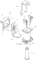
- the movable iron piece 4 is formed by pressing a plate-like magnetic material into a substantially L shape by pressing.
- One end side of the movable iron piece 4 is a portion to be attracted 88 that is attracted to the magnetic pole portion 54 of the iron core 51.
- the tip and base of the suctioned portion 88 are narrow, and interference between the guide projection 66 formed on the bottom surface of the spool 52 and the projection 72 formed on the lower end of the yoke 55 is avoided. .
- An opening 89 is formed on the other end side of the movable iron piece 4.
- through holes 90 are formed at two locations in the upper part of the opening 89, and the protrusion 93 a of the card member 65 is integrated by heat crimping.
- slits 91 are formed on both sides of the heat caulking position, and when the concave portion 92 is formed to prevent the resin from protruding during the heat caulking, lateral deformation at the portion is allowed. Provides a space to do.
- the card member 65 is made of a synthetic resin material, and a depression 93 in which the upper end side of the movable iron piece 4 is disposed is formed on one surface.
- Protrusions 93a are formed at two locations in the upper and lower portions of the recess 93, and these are used for heat caulking after being inserted into the through hole 90 of the movable iron piece 4.
- three rows of first ribs 94 extending in the vertical direction are formed on the other surface of the card member.
- the upper ends of the first ribs 94 are connected to each other by a connecting wall 95, and protrusions 96 are formed in pairs on the left and right sides from the front edge of the first rib 94 toward the front.
- the upper end portion of the movable contact piece 79 is guided between each pair of protrusions 18 and is pressed against the front end portion of the connecting wall 95.
- a first shielding wall 97 that protrudes forward is formed at the upper end of the card member 65, and a second shielding wall 98 that protrudes forward and then extends downward is formed at the lower end.
- the case 5 is made of a synthetic resin material in a box shape with an open bottom surface. Resin sealing holes 99 are formed in the upper corners of the case 5. The resin sealing hole 99 is heat sealed after sealing the fitting portion between the base block 1 and the case 5. On the upper surface edge of the case 5 (on the side opposite to the resin sealing hole 99), slit-shaped recesses 100 are formed on both sides. A recess 101 that is recessed from the upper surface is formed between the recesses 100, and a protrusion 102 is formed at the center of the upper surface.
- 5a is an attachment part for screwing and fixing an electromagnetic relay.
- An arc extinguishing member 103 is attached to the case 5 using the recess 100 and the recess 101.
- the arc extinguishing member 103 includes a pair of permanent magnets 104a and 104b arranged at predetermined intervals to extinguish the arc, and a connecting member 105 made of a magnetic material for magnetically connecting the permanent magnets 104a and 104b. It consists of
- the permanent magnets 104a and 104b have a substantially rectangular parallelepiped shape, and are arranged so that the opposing surfaces have different polarities when attached to the inner surfaces of the opposing walls 106 of the connecting member 105.
- the polarity of the facing surface may be set so that the direction of the force acting on the arc current is directed to the intermediate wall 107 side of the connecting member 105 described later according to the difference in the direction of current flow between the contacts.
- the connecting member 105 is a plate-like magnetic material bent by pressing so that both end sides face each other. Permanent magnets 104a and 104b are attracted and fixed to the inner surface of each facing wall 106 by their own magnetic force. The magnetic flux generated from one of the permanent magnets 104a and 104b forms a closed loop as a magnetic circuit that returns from the other permanent magnet 104a and 104b via the connecting member 105.
- the arc extinguishing member 103 not only the pair of permanent magnets 104a and 104b but also the connecting member 105 for magnetically connecting them is provided. For this reason, the magnetic circuit used as a closed loop is formed and it becomes difficult to generate magnetic flux leakage. As a result, even if an arc is generated when the contact is opened and closed, the arc is extended in a direction perpendicular to the direction in which the arc current flows according to the Fleming left-hand rule, and is extinguished in a short time.
- the coil 53 is wound around the trunk portion 57 of the spool 52, and the coil terminal 67 is press-fitted and fixed in the terminal holding hole 62 of the lower end side flange portion 59. Both ends of the coil 53 are wound around the coil winding portion 68 of the coil terminal 67 and soldered. Further, the iron core 51 is inserted into the center hole 56 of the spool 52 from the lower end side, and the yoke 55 is caulked and fixed to a portion protruding from the upper end. Thereby, the electromagnet block 2 is completed.
- the completed electromagnet block 2 is mounted on the first base portion 6.
- the card member 65 is attached to the first mounting portion 8 of the first base portion 6 together with the movable iron piece 4 and the hinge spring 44. That is, the locking portion 77 of the hinge spring 44 is positioned in the protrusion 18 and the recess 19 of the first base portion 6.
- the movable iron piece 4 is arrange
- the electromagnet block 2 is fixed to the first base portion 6 by positioning the guide protrusion 66 in the positioning recess 12, inserting both ends of the yoke 55 into the guide groove 17, and press-fitting the coil terminal 67 into the coil terminal hole 13. To do. Thereby, the movable iron piece 4 is rotatably supported by the lower end corner portion of the yoke 55.
- the bottom surface of the projecting portion 72 of the yoke 55 and the bottom surface of the terminal mounting portion 61 of the spool 52 are in contact with the top surface of the base portion 10 of the first base portion 6.
- a gap in which the movable iron piece 4 is rotatable is formed between the upper surface of the base portion 10 of the first base portion 6 and the magnetic pole portion 54 of the iron core 51 exposed at the lower end portion of the spool 52.
- the shielding wall 70 of the card member 65 integrated with the movable iron piece 4 is disposed beyond the insulating wall 16 of the base block 1.
- the guide wall 15 and the insulating wall 16 of the base block 1 and the shielding walls 97 and 98 of the card member 65 sufficiently ensure insulation between the electromagnet block 2 and the contact opening / closing part 3.
- the contact opening / closing part 3 is attached to the first base part 6.
- the terminal part 79d of the movable contact piece 79 is inserted into the first terminal holes 22a and 22b, and the press-fitting part 79c is press-fitted and fixed.
- the upper end portion of the movable contact piece 79 is sandwiched between the projections 96 of the card member 65 that has been previously mounted, and is brought into pressure contact with the connecting portion 73.
- the elastic force of the movable contact piece 79 acts on the movable iron piece 4, and the movable iron piece 4 is positioned at the initial position where the attracted part 88 is separated from the magnetic pole part 54 of the iron core 51.
- the terminal portion 78b of the fixed contact piece 78 is inserted into the second terminal holes 24a and 24b of the first base portion 6, and the press-fit portion 78a is press-fitted and fixed.
- the fixed contact piece 78 faces the movable contact piece 79 at a predetermined interval, and the movable contact 81 can be brought into contact with and separated from the fixed contact 80.
- one movable contact piece 79A protruding from the bottom surface of the first base portion 6 and one fixed contact piece 78B are connected by the connection terminal 39. That is, the terminal part 79d of one movable contact piece 79A and the terminal part 78b of one fixed contact piece 78B are inserted into the through holes 40a and 40b of the connection terminal 39, respectively, and are electrically connected by soldering.
- the second base part 7 to which the tab terminals 41, 42, 45, 46 are fixed is mounted on the first base part 6.
- the press-fit portions 41b, 42b, 45b, 46b of the tab terminals 41, 42, 45, 46 are press-fitted into the press-fit holes 29a-29c of the second base portion 7, respectively. To do.
- connection portions 41c, 42c, 45c, 46c of the tab terminals 41, 42, 45, 46 are arranged in the recesses 31, 32, 34, 35 formed on the bottom surface of the first base portion 6, and each connection
- the through holes 41d, 42d, 45c, and 46e of the portions 41c, 42c, 45c, and 46c coincide with the positions of the through holes 28a to 28d of the second base portion 7.
- the lower end portion of the first base portion 6 is fitted and integrated into the rectangular recess 26 of the second base portion 7.
- the terminal portion 47 of the coil terminal 67 is inserted into the through hole 41 d of the first tab terminal 41 and the through hole 42 d of the second tab terminal 42.
- the terminal portion 79 d of the movable contact piece 79 is inserted into the through hole 45 e of the third tab terminal 46
- the terminal portion 78 b of the fixed contact piece 78 is inserted into the through hole 46 e of the fourth tab terminal 45. Therefore, the terminal portions 78b and 79d of the contact pieces 78B and 79A inserted through the through holes 28a to 28d are electrically connected by soldering.
- the arc extinguishing member 103 is attached to the case 5.
- each of the concave portions 100 formed in the case 5, with the permanent magnets 104 a and 104 b attached to the opposing wall 106 of the connecting member 105. 104b is respectively inserted.
- the connecting member 105 is fixed to the case 5 by heat caulking.
- the case 5 to which the arc extinguishing member 103 is attached is put on the base block 1, and the fitting portion of both is sealed.
- the internal space may be sealed by thermally sealing the resin sealing hole 99.
- the resin sealing hole 99 can be left open and the internal space can be used in communication with the surrounding atmosphere.
- the other components except for the second base can be used as they are, with almost no change in the configuration used conventionally.
- the 2nd base part 7 it can be set as the electromagnetic relay corresponding to another form.
- the connection terminal 39 is provided to connect the movable contact piece 79 and the fixed contact piece 78 so that the contact points are opened and closed at two locations along the same electric circuit.
- the four tab terminals 41, 42, 45, 46 it is possible to freely set the electrical connection position to other components (for example, a printed circuit board) of the electromagnetic relay.
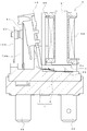
- the attracted portion 88 is made to be an iron core around the fulcrum supported by the yoke 55 by the elastic force of the movable contact pieces 79A and 79B. It is located at an initial position away from the magnetic pole portion 54 of the 51. Therefore, the movable contact 81 maintains an open state separated from the fixed contact 80.
- the movable iron piece 4 When the coil 53 is energized and the electromagnet block 2 is energized, the movable iron piece 4 is attracted to the attracted portion 88 by the magnetic pole portion 54 of the iron core 51 and resists the urging force of the movable contact pieces 79A and 79B, as shown in FIG. Then rotate. Thereby, the movable contact pieces 79 ⁇ / b> A and 79 ⁇ / b> B are elastically deformed, and the movable contact 81 is closed to the fixed contact 80 of the fixed contact piece 78.
- the movable iron piece 4 loses the attractive force of the iron core 51 and rotates by the elastic force of the movable contact pieces 79A and 79B, as shown in FIG. Then, the movable contact 81 is separated from the fixed contact 80.
- the magnetic flux generated from the N pole of one permanent magnet 104 a reaches the S pole of the other permanent magnet 104 b and returns to the S pole of one permanent magnet 104 a through the connection member 105.
- the connection member 105 is provided as compared with the case where only the permanent magnets 104a and 104b are disposed, the magnetic flux density at the contact opening / closing position can be improved by 53.3%.
- a force was applied to the generated arc in a direction perpendicular to the contact opening direction, and this arc was greatly extended and extinguished rapidly.
- the magnetic poles of the permanent magnets 104a and 104b are set to have different polarities on the opposing surfaces so that a magnetic flux direction that can deform the arc toward the intermediate wall 107 side of the connecting member 105 is obtained. In other words, the arc is more reliably extinguished by deforming the arc toward the intermediate wall 107 side of the connecting member 105.
Abstract
Priority Applications (4)
| Application Number | Priority Date | Filing Date | Title |
|---|---|---|---|
| US13/982,870 US9082575B2 (en) | 2011-03-14 | 2011-03-25 | Electromagnetic relay |
| CN201180066370.XA CN103339705B (zh) | 2011-03-14 | 2011-03-25 | 电磁继电器 |
| KR1020137003960A KR101435349B1 (ko) | 2011-03-14 | 2011-03-25 | 전자 계전기 |
| EP11860930.4A EP2688083B1 (fr) | 2011-03-14 | 2011-03-25 | Relais électromagnétique |
Applications Claiming Priority (6)
| Application Number | Priority Date | Filing Date | Title |
|---|---|---|---|
| JP2011055725A JP5085754B2 (ja) | 2011-03-14 | 2011-03-14 | 電磁継電器 |
| JP2011-055725 | 2011-03-14 | ||
| JP2011-055721 | 2011-03-14 | ||
| JP2011055721A JP4883232B1 (ja) | 2011-03-14 | 2011-03-14 | 電磁継電器 |
| JP2011056915A JP5085755B2 (ja) | 2011-03-15 | 2011-03-15 | 電磁継電器 |
| JP2011-056915 | 2011-03-15 |
Publications (1)
| Publication Number | Publication Date |
|---|---|
| WO2012124174A1 true WO2012124174A1 (fr) | 2012-09-20 |
Family
ID=46830278
Family Applications (1)
| Application Number | Title | Priority Date | Filing Date |
|---|---|---|---|
| PCT/JP2011/057282 WO2012124174A1 (fr) | 2011-03-14 | 2011-03-25 | Relais électromagnétique |
Country Status (5)
| Country | Link |
|---|---|
| US (1) | US9082575B2 (fr) |
| EP (1) | EP2688083B1 (fr) |
| KR (1) | KR101435349B1 (fr) |
| CN (1) | CN103339705B (fr) |
| WO (1) | WO2012124174A1 (fr) |
Cited By (2)
| Publication number | Priority date | Publication date | Assignee | Title |
|---|---|---|---|---|
| CN104143478A (zh) * | 2013-02-13 | 2014-11-12 | 欧姆龙株式会社 | 电磁继电器 |
| EP2741307A3 (fr) * | 2012-12-07 | 2015-06-17 | Fujitsu Component Limited | Relais électromagnétique |
Families Citing this family (12)
| Publication number | Priority date | Publication date | Assignee | Title |
|---|---|---|---|---|
| JP6422249B2 (ja) * | 2014-07-03 | 2018-11-14 | 富士通コンポーネント株式会社 | 電磁継電器 |
| US9865420B2 (en) * | 2014-07-23 | 2018-01-09 | Fujitsu Component Limited | Electromagnetic relay |
| JP6433706B2 (ja) * | 2014-07-28 | 2018-12-05 | 富士通コンポーネント株式会社 | 電磁継電器及びコイル端子 |
| KR101943363B1 (ko) | 2015-04-13 | 2019-04-17 | 엘에스산전 주식회사 | 전자개폐기 |
| JP6556514B2 (ja) * | 2015-06-19 | 2019-08-07 | 富士通コンポーネント株式会社 | 電磁継電器 |
| JP6657692B2 (ja) * | 2015-09-11 | 2020-03-04 | オムロン株式会社 | 電磁石装置およびこれを用いた電磁継電器 |
| JP6981732B2 (ja) * | 2015-09-28 | 2021-12-17 | 富士通コンポーネント株式会社 | 電磁継電器 |
| JP6701841B2 (ja) * | 2016-03-15 | 2020-05-27 | オムロン株式会社 | 電気接点開閉装置 |
| JP2018006209A (ja) * | 2016-07-05 | 2018-01-11 | 富士通コンポーネント株式会社 | 電磁継電器 |
| JP6836241B2 (ja) * | 2016-12-27 | 2021-02-24 | 富士通コンポーネント株式会社 | 電磁継電器 |
| JP6926738B2 (ja) * | 2017-07-04 | 2021-08-25 | オムロン株式会社 | 電磁継電器 |
| JP7149824B2 (ja) * | 2018-11-30 | 2022-10-07 | 富士通コンポーネント株式会社 | 電磁継電器 |
Citations (5)
| Publication number | Priority date | Publication date | Assignee | Title |
|---|---|---|---|---|
| JPS5511064U (fr) * | 1978-06-30 | 1980-01-24 | ||
| JPS5534346U (fr) * | 1978-08-28 | 1980-03-05 | ||
| JPS60107551U (ja) * | 1983-12-26 | 1985-07-22 | オムロン株式会社 | 電磁継電器 |
| JP2001176370A (ja) * | 1999-12-16 | 2001-06-29 | Denso Corp | 電磁継電器 |
| JP2007305466A (ja) * | 2006-05-12 | 2007-11-22 | Omron Corp | 電磁継電器 |
Family Cites Families (52)
| Publication number | Priority date | Publication date | Assignee | Title |
|---|---|---|---|---|
| US2735968A (en) * | 1956-02-21 | Relay structure | ||
| US2875304A (en) | 1956-03-30 | 1959-02-24 | Westinghouse Electric Corp | Circuit interrupter |
| JPS538901B2 (fr) * | 1971-09-01 | 1978-04-01 | ||
| DE2912800C2 (de) * | 1979-03-30 | 1985-04-25 | Siemens AG, 1000 Berlin und 8000 München | Elektromagnetisches Relais für hohe Schaltleistungen |
| JPS5713628A (en) * | 1980-06-27 | 1982-01-23 | Mitsubishi Electric Corp | Direct current electromagnetic contactor |
| DE3414731C2 (de) * | 1984-04-18 | 1986-03-20 | Hengstler GmbH, Geschäftsbereich Haller-Relais, 7209 Wehingen | Kleinstrelais |
| JPS63149039U (fr) * | 1987-03-20 | 1988-09-30 | ||
| US4758809A (en) * | 1987-09-17 | 1988-07-19 | Potter And Brumfield Inc. | Electromagnetic relay having a multifunction retaining spring |
| US4761627A (en) * | 1987-09-17 | 1988-08-02 | Potter And Brumfield Inc. | Electromagnetic relay including a rotatable armature mount |
| JP2658170B2 (ja) * | 1988-05-11 | 1997-09-30 | オムロン株式会社 | 開閉器 |
| DE3835118A1 (de) * | 1988-10-14 | 1990-04-19 | Siemens Ag | Elektromagnetisches relais |
| JPH02126344U (fr) * | 1989-03-28 | 1990-10-18 | ||
| US5041870A (en) | 1988-10-21 | 1991-08-20 | Omron Tateisi Electronics Co. | Electromagnetic relay |
| EP0372554A3 (fr) * | 1988-12-09 | 1992-04-08 | OMRON Corporation | Relais électromagnétique |
| JPH0346728A (ja) * | 1989-07-13 | 1991-02-28 | Omron Corp | 電磁継電器 |
| JPH0469836U (fr) * | 1990-10-26 | 1992-06-19 | ||
| EP0501070B2 (fr) * | 1991-02-27 | 2003-05-14 | Takamisawa Electric Co., Ltd. | Relais électromagnétique de petite dimension |
| DE69230100T2 (de) * | 1991-04-09 | 2000-06-08 | Omron Tateisi Electronics Co | Elektromagnetisches relais |
| JP3383984B2 (ja) * | 1992-05-14 | 2003-03-10 | オムロン株式会社 | 電磁継電器 |
| US5289144A (en) * | 1992-08-21 | 1994-02-22 | Potter & Brumfield, Inc. | Electromagnetic relay and method for assembling the same |
| DE4300594A1 (de) * | 1993-01-13 | 1994-07-14 | Hengstler Bauelemente | Sicherheitsrelais mit zwangsgeführtem Kontaktsatz und monostabilem Antrieb |
| US5321377A (en) * | 1993-01-21 | 1994-06-14 | Kaloust P. Sagoian | Electromagnet for relays and contactor assemblies |
| DE4405222C1 (de) * | 1994-02-18 | 1995-05-11 | Siemens Ag | Verfahren zur Herstellung eines Relais mit beweglichem Schieber und nach dem Verfahren hergestelltes Relais |
| US5416455A (en) * | 1994-02-24 | 1995-05-16 | Eaton Corporation | Direct current switching apparatus |
| JPH07254340A (ja) * | 1994-03-15 | 1995-10-03 | Omron Corp | 電磁継電器 |
| WO1995030995A1 (fr) | 1994-05-05 | 1995-11-16 | Siemens Aktiengesellschaft | Relais modulaire |
| IT233985Y1 (it) * | 1994-07-29 | 2000-02-16 | Gavazzi Carlo Electromatic | Rele' elettromagnetico pluricontatto miniatura per usi industriali |
| US5864270A (en) * | 1995-03-21 | 1999-01-26 | Siemens Aktiengesellschaft | Electromagnetic relay |
| US5805040A (en) * | 1996-09-27 | 1998-09-08 | Simens Electromechanical Components, Inc. | Relay base and method of assembly |
| JP3713850B2 (ja) | 1996-11-25 | 2005-11-09 | 松下電工株式会社 | 直流開閉器 |
| DE19804572A1 (de) * | 1997-05-05 | 1999-08-12 | Schrack Components Ag | Relais mit Kontaktfedern |
| DE19727991C1 (de) * | 1997-07-01 | 1998-11-19 | Schrack Components Ag | Elektromagnetisches Relais |
| EP0938119A1 (fr) * | 1998-02-18 | 1999-08-25 | ELESTA relays GmbH | Relais |
| EP1009008B1 (fr) * | 1998-12-07 | 2006-05-31 | Matsushita Electric Works, Ltd. | Relais électromagnétique |
| WO2001027950A1 (fr) | 1999-10-14 | 2001-04-19 | Matsushita Electric Works, Ltd. | Contacteur |
| JP4212248B2 (ja) * | 2001-02-09 | 2009-01-21 | 富士通コンポーネント株式会社 | 電磁継電器 |
| JP4334158B2 (ja) * | 2001-03-26 | 2009-09-30 | 富士通コンポーネント株式会社 | 電磁継電器 |
| US6798322B2 (en) * | 2002-06-17 | 2004-09-28 | Tyco Electronics Corporation | Low noise relay |
| JP4131161B2 (ja) * | 2002-11-12 | 2008-08-13 | オムロン株式会社 | 電磁継電器 |
| JP4190379B2 (ja) * | 2003-09-12 | 2008-12-03 | 富士通コンポーネント株式会社 | 複合型電磁継電器 |
| JP4424260B2 (ja) * | 2005-06-07 | 2010-03-03 | オムロン株式会社 | 電磁リレー |
| JP4810937B2 (ja) * | 2005-09-06 | 2011-11-09 | オムロン株式会社 | 開閉装置 |
| JP4742954B2 (ja) * | 2006-03-31 | 2011-08-10 | オムロン株式会社 | 電磁継電器 |
| US7477119B2 (en) * | 2007-03-02 | 2009-01-13 | Good Sky Electric Co., Ltd. | Electromagnetic relay |
| JP4946559B2 (ja) * | 2007-03-22 | 2012-06-06 | オムロン株式会社 | 電磁継電器 |
| JP5058643B2 (ja) * | 2007-03-26 | 2012-10-24 | 富士通コンポーネント株式会社 | 電磁継電器 |
| US8193881B2 (en) * | 2007-09-14 | 2012-06-05 | Fujitsu Component Limited | Relay |
| EP2267746B1 (fr) | 2008-03-19 | 2015-07-08 | Panasonic Intellectual Property Management Co., Ltd. | Dispositif de contact |
| JP5163318B2 (ja) * | 2008-06-30 | 2013-03-13 | オムロン株式会社 | 電磁石装置 |
| TW201019364A (en) * | 2008-11-12 | 2010-05-16 | Good Sky Electric Co Ltd | An electromagnetic relay |
| JP5511064B2 (ja) | 2010-05-07 | 2014-06-04 | 株式会社三谷バルブ | 定量噴射機構および、この定量噴射機構を備えたエアゾール式製品 |
| JP5923932B2 (ja) * | 2011-11-04 | 2016-05-25 | オムロン株式会社 | 接点開閉機構及び電磁継電器 |
-
2011
- 2011-03-25 US US13/982,870 patent/US9082575B2/en active Active
- 2011-03-25 CN CN201180066370.XA patent/CN103339705B/zh active Active
- 2011-03-25 EP EP11860930.4A patent/EP2688083B1/fr active Active
- 2011-03-25 KR KR1020137003960A patent/KR101435349B1/ko active IP Right Grant
- 2011-03-25 WO PCT/JP2011/057282 patent/WO2012124174A1/fr active Application Filing
Patent Citations (5)
| Publication number | Priority date | Publication date | Assignee | Title |
|---|---|---|---|---|
| JPS5511064U (fr) * | 1978-06-30 | 1980-01-24 | ||
| JPS5534346U (fr) * | 1978-08-28 | 1980-03-05 | ||
| JPS60107551U (ja) * | 1983-12-26 | 1985-07-22 | オムロン株式会社 | 電磁継電器 |
| JP2001176370A (ja) * | 1999-12-16 | 2001-06-29 | Denso Corp | 電磁継電器 |
| JP2007305466A (ja) * | 2006-05-12 | 2007-11-22 | Omron Corp | 電磁継電器 |
Cited By (2)
| Publication number | Priority date | Publication date | Assignee | Title |
|---|---|---|---|---|
| EP2741307A3 (fr) * | 2012-12-07 | 2015-06-17 | Fujitsu Component Limited | Relais électromagnétique |
| CN104143478A (zh) * | 2013-02-13 | 2014-11-12 | 欧姆龙株式会社 | 电磁继电器 |
Also Published As
| Publication number | Publication date |
|---|---|
| KR101435349B1 (ko) | 2014-08-27 |
| US9082575B2 (en) | 2015-07-14 |
| CN103339705A (zh) | 2013-10-02 |
| CN103339705B (zh) | 2017-02-15 |
| EP2688083B1 (fr) | 2019-07-03 |
| US20140022035A1 (en) | 2014-01-23 |
| EP2688083A1 (fr) | 2014-01-22 |
| KR20130038931A (ko) | 2013-04-18 |
| EP2688083A4 (fr) | 2014-10-29 |
Similar Documents
| Publication | Publication Date | Title |
|---|---|---|
| WO2012124174A1 (fr) | Relais électromagnétique | |
| JP5085755B2 (ja) | 電磁継電器 | |
| JP5085754B2 (ja) | 電磁継電器 | |
| JP4883232B1 (ja) | 電磁継電器 | |
| US7782162B2 (en) | Switching device | |
| JP5923932B2 (ja) | 接点開閉機構及び電磁継電器 | |
| JP5741338B2 (ja) | 端子部材のシール構造、及び、電磁継電器 | |
| JP2009230921A (ja) | 接点装置 | |
| JP4586861B2 (ja) | 電磁継電器 | |
| JP2005166431A (ja) | 電磁継電器 | |
| JP4645659B2 (ja) | 電磁継電器 | |
| JP3959894B2 (ja) | 電磁継電器 | |
| JP2020155259A (ja) | 電磁継電器 | |
| JP2014203784A (ja) | 接点装置およびそれを用いた電磁リレー | |
| JP4091012B2 (ja) | 回路遮断器 | |
| JP2014203785A (ja) | 接点装置およびそれを用いた電磁リレー | |
| JPH0817316A (ja) | 電磁リレー |
Legal Events
| Date | Code | Title | Description |
|---|---|---|---|
| 121 | Ep: the epo has been informed by wipo that ep was designated in this application |
Ref document number: 11860930 Country of ref document: EP Kind code of ref document: A1 |
|
| ENP | Entry into the national phase |
Ref document number: 20137003960 Country of ref document: KR Kind code of ref document: A |
|
| WWE | Wipo information: entry into national phase |
Ref document number: 2011860930 Country of ref document: EP |
|
| NENP | Non-entry into the national phase |
Ref country code: DE |
|
| WWE | Wipo information: entry into national phase |
Ref document number: 13982870 Country of ref document: US |