WO2012121026A1 - Dispositif de revêtement et méthode de revêtement - Google Patents
Dispositif de revêtement et méthode de revêtement Download PDFInfo
- Publication number
- WO2012121026A1 WO2012121026A1 PCT/JP2012/054503 JP2012054503W WO2012121026A1 WO 2012121026 A1 WO2012121026 A1 WO 2012121026A1 JP 2012054503 W JP2012054503 W JP 2012054503W WO 2012121026 A1 WO2012121026 A1 WO 2012121026A1
- Authority
- WO
- WIPO (PCT)
- Prior art keywords
- width
- width direction
- substrate
- air
- discharge port
- Prior art date
Links
Images

Classifications
-
- B—PERFORMING OPERATIONS; TRANSPORTING
- B05—SPRAYING OR ATOMISING IN GENERAL; APPLYING FLUENT MATERIALS TO SURFACES, IN GENERAL
- B05D—PROCESSES FOR APPLYING FLUENT MATERIALS TO SURFACES, IN GENERAL
- B05D1/00—Processes for applying liquids or other fluent materials
- B05D1/26—Processes for applying liquids or other fluent materials performed by applying the liquid or other fluent material from an outlet device in contact with, or almost in contact with, the surface
-
- B—PERFORMING OPERATIONS; TRANSPORTING
- B05—SPRAYING OR ATOMISING IN GENERAL; APPLYING FLUENT MATERIALS TO SURFACES, IN GENERAL
- B05C—APPARATUS FOR APPLYING FLUENT MATERIALS TO SURFACES, IN GENERAL
- B05C5/00—Apparatus in which liquid or other fluent material is projected, poured or allowed to flow on to the surface of the work
- B05C5/02—Apparatus in which liquid or other fluent material is projected, poured or allowed to flow on to the surface of the work the liquid or other fluent material being discharged through an outlet orifice by pressure, e.g. from an outlet device in contact or almost in contact, with the work
- B05C5/0254—Coating heads with slot-shaped outlet
-
- B—PERFORMING OPERATIONS; TRANSPORTING
- B05—SPRAYING OR ATOMISING IN GENERAL; APPLYING FLUENT MATERIALS TO SURFACES, IN GENERAL
- B05D—PROCESSES FOR APPLYING FLUENT MATERIALS TO SURFACES, IN GENERAL
- B05D3/00—Pretreatment of surfaces to which liquids or other fluent materials are to be applied; After-treatment of applied coatings, e.g. intermediate treating of an applied coating preparatory to subsequent applications of liquids or other fluent materials
- B05D3/04—Pretreatment of surfaces to which liquids or other fluent materials are to be applied; After-treatment of applied coatings, e.g. intermediate treating of an applied coating preparatory to subsequent applications of liquids or other fluent materials by exposure to gases
- B05D3/0406—Pretreatment of surfaces to which liquids or other fluent materials are to be applied; After-treatment of applied coatings, e.g. intermediate treating of an applied coating preparatory to subsequent applications of liquids or other fluent materials by exposure to gases the gas being air
- B05D3/042—Directing or stopping the fluid to be coated with air
Definitions
- the present invention relates to a coating apparatus and a coating method for coating a substrate by discharging a coating liquid onto a substrate.
- a substrate for performing photoelectric conversion is used in the solar cell panel, and this substrate is manufactured through a step of applying a predetermined coating solution to a glass substrate to form a coating film.
- a coating apparatus provided with a slit nozzle having a discharge port composed of a slit that is long in the width direction (see, for example, Patent Document 1).
- the coating solution is discharged, and a coating film is formed on the substrate with the coating solution.
- the coating film formed on the glass substrate may be formed so as to protrude greatly on both sides in the width direction from the discharge port.
- the film thickness on both sides in the width direction of the film becomes thin. This is because the clearance between the lower end surface where the discharge port of the slit die opens and the substrate is very small, so that the discharged coating liquid is discharged due to capillary action between the lower end surface of the slit die and the substrate. It is thought that it protrudes further outward from both ends in the width direction of the outlet. Therefore, in the apparatus described in Patent Document 1, notches (or steps) are provided in the extended portions on both sides in the width direction of the discharge port to prevent the discharged coating liquid from spreading in the width direction.
- Patent Document 1 it is possible to suppress fluctuations in the width direction dimension of the coating film due to the applied coating liquid with respect to a desired value.
- this is possible only when the discharge width of the coating liquid from the slit is constant (fixed), and it is necessary to replace the slit die in order to change the discharge width.
- the slit die When the slit die is replaced, it is necessary to readjust the clearance between the lower end surface where the discharge port is opened and the substrate, and it takes time to change the discharge width.
- an object of the present invention is to provide a coating apparatus and a coating method capable of suppressing fluctuations in the dimension in the width direction of the coating film due to the coated coating liquid while easily changing the discharge width.
- the coating apparatus includes a slit nozzle that has a discharge port formed of a slit that is long in the width direction and applies a coating solution by discharging the coating liquid onto the substrate from the discharge port, and the slit nozzle and the substrate relatively
- a drive unit that moves in the front-rear direction orthogonal to the width direction, a discharge width changing member that is provided in the slit and changes the width direction dimension of the discharge port by moving in the width direction in the slit, and the discharge port
- An air supply that has an air nozzle that blows air to the regions on both outer sides in the width direction of the coating liquid discharged from the air, and the air blowing position by the air nozzle can be adjusted according to a change in the width direction dimension of the discharge port And a unit.
- the present invention is also a coating method in which a coating film made of a coating solution is formed on a substrate by the coating apparatus, the width-direction dimension of the coating film, the position adjustment of the discharge width changing member, and the air supply unit And the adjustment of the air blowing position by the air nozzle.
- the air nozzle of the air supply unit blows air onto the regions on both outer sides in the width direction of the coating liquid discharged from the discharge port. It is possible to prevent the coating film from being formed from spreading in the width direction, and to suppress the variation in the width direction dimension of the coating film. And by changing the width direction dimension of the discharge port by the discharge width changing member, the discharge width can be easily changed, and in the air supply unit, depending on the change of the width direction dimension of the discharge port, Since the air spray position can be adjusted, even if the discharge width is changed, the function of suppressing the variation in the dimension of the coating film in the width direction is maintained.
- the discharge width changing member has a shape that protrudes toward the substrate from the end surface where the discharge port of the slit nozzle is open, and is rounded up in the direction away from the substrate toward the outside in the width direction. It is preferable to have the protrusion part which has.
- the cause of the variation in the width direction dimension of the coating film due to the applied coating solution is due to the characteristics of the coating solution and the clearance between the end surface where the discharge port of the slit nozzle opens and the substrate. In some cases, the discharged coating liquid narrows in the width direction (the coating liquid is pulled toward the center in the width direction).
- the coating liquid is captured by the projecting portion, and fluctuations in the width direction dimension of the coating film can be suppressed.
- the protruding portion has a shape that is rounded up in the direction away from the substrate toward the outer side in the width direction, it is possible to prevent the coating liquid from spreading in the width direction due to the edge effect due to the shape.
- the function of suppressing this spread is reinforced by the air supply unit.
- the air nozzle outlet of the air nozzle has a height corresponding to a clearance from the substrate to the discharge port in the vicinity of both outer sides in the width direction of the coating liquid discharged from the discharge port and the slit. It is preferable to have a center line on a virtual straight line that crosses the substrate after passing through the neighboring region having a minute width including the width in the front-rear direction. In this case, air can flow in the vicinity of both outer sides in the width direction of the coating liquid discharged from the discharge port and placed on the substrate, and the dynamic pressure of the air reliably suppresses the spreading of the coating liquid to the outer side in the width direction. Is possible.
- variety” it can be set as the width
- the present invention provides a slit nozzle in which a discharge port composed of a long slit in the width direction is formed and discharges and applies a coating liquid to the substrate from the discharge port, and the slit nozzle and the substrate are relatively
- a drive unit that moves in the front-rear direction orthogonal to the width direction; and a discharge width changing member that is provided in the slit and changes the width direction dimension of the discharge port by moving in the width direction in the slit.
- the width changing member has a protruding portion that protrudes toward the substrate side from the end surface where the discharge port of the slit nozzle is open, and has a shape that is rounded up in the direction away from the substrate toward the outside in the width direction. It is characterized by having.
- the discharge width can be easily changed by changing the width direction dimension of the discharge port by the discharge width changing member, and the protrusion of the discharge width changing member is the slit nozzle.
- the protruding portion has a shape that is rounded up in the direction away from the substrate toward the outer side in the width direction, it is possible to prevent the coating liquid from spreading in the width direction due to the edge effect due to the shape.
- the present invention it is possible to suppress the change in the width direction dimension of the coating film due to the applied coating liquid while easily changing the discharge width.
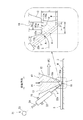
- FIG. 1 is a schematic view showing an embodiment of the coating apparatus of the present invention.
- the coating apparatus includes a base 1, a guide member 2 provided on the base 1, a stage 3 that can be moved in the front-rear direction by the guide member 2 and on which a substrate W can be placed, and the stage 3 is moved in the front-rear direction. And a drive unit 4 to be moved.
- the coating apparatus includes a slit nozzle 10 that discharges and applies a coating liquid onto the substrate W on the stage 3.
- the substrate W is a rectangular sheet member, and is a glass substrate for a solar cell panel in the present embodiment.
- the guide member 2 is a guide for guiding the stage 3 in the front-rear direction, and the drive unit 4 moves the stage 3 in the front-rear direction.
- the drive unit 4 has, for example, a ball screw mechanism that is rotated by a servo motor (not shown), and the movement of the stage 3 in the front-rear direction and its movement position can be controlled by this ball screw mechanism.
- the stage 3 can place the substrate W on the upper surface thereof, and can hold (fix) the substrate W by, for example, air suction force or electrostatic force.
- the base 1 is provided with a slit nozzle column (not shown), and the slit nozzle 10 is fixed to the column.
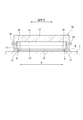
- FIG. 2 is an enlarged cross-sectional view of the lower portion of the slit nozzle 10 as viewed in the width direction.
- FIG. 3 is a cross-sectional view of the slit nozzle 10 as viewed from the front. 1 to 3, the slit nozzle 10 has a main body block 14, a front lip 12, and a rear lip 13 that are block-shaped and long in the width direction. The lips 12, 13 have a gap in the front-rear direction. And is integrated with the main body block 14. A long hole (manifold) 15 in the width direction is formed in the main body block 14, and this hole 15 communicates with a long slit 16 formed between the lips 12 and 13.
- the longitudinal direction of the slit 16 coincides with the width direction of the coating apparatus, and the direction orthogonal to the width direction is the front-rear direction.
- the coating apparatus further includes a tank 5 storing the coating liquid L, a pump unit 6 having a pump and a valve, and a pipe 7 through which the coating liquid L flows, and the pump unit 6 is driven.
- the coating liquid L in the tank 5 can be supplied to the slit nozzle 10 through the pipe 7.
- the coating liquid L supplied to the slit nozzle 10 flows to the slit 16 through the hole (manifold) 15, and is then discharged onto the substrate W. That is, the slit 16 becomes the discharge port 11 from which the coating liquid L is discharged.
- the slit nozzle 10 has the discharge port 11 formed of the slit 16, and the coating liquid L can be discharged and applied to the substrate W from the discharge port 11.
- the coating liquid L continuously discharged from the discharge port 11 is discharged in the form of a strip that is long in the width direction.
- the stage 3 holding the substrate W is moved rearward by the driving unit 4, thereby A coating film S is formed on the substrate W by the coating liquid L.
- the dimension of the width direction of the coating film S is called the application width B.
- the slit nozzle 10 is provided with a discharge width changing member 17 that moves in the slit 16 in the width direction.
- the discharge width changing member 17 is a thin plate member provided in the slit 16.
- the discharge width changing member 17 is slightly thinner than the width of the slit 16 (the dimension in the front-rear direction). It is possible to prevent leaking to the outside (regulating the flow further outward in the width direction). For this reason, the width direction dimension (discharge width) of the discharge port 11 which becomes the width at which the coating liquid is discharged is defined by the discharge width changing member 17, and the discharge width changing member 17 is moved in the width direction.
- the width direction dimension (discharge width) of the discharge port 11 can be changed.
- the width direction dimension of the discharge port 11 means a width dimension that allows the application liquid L to be discharged, and the application width B by the application liquid can be changed by changing the discharge width.
- the discharge width changing member 17 can change the coating width B to various values without replacing the slit nozzle 10.
- the discharge width changing member 17 is integrated with a piston 18 that advances and retracts in the width direction in the hole 15, and a shaft 19 that moves the piston 18 forward and backward is provided in the slit nozzle 10. Yes. By moving the shaft 19 in the width direction, the position in the width direction of the discharge width changing member 17 can be adjusted, and the coating width B can be changed.
- the discharge width changing member 17 is positioned and used at a predetermined position.
- the application width B is a width.
- the coating apparatus includes a discharge width variation suppressing mechanism that suppresses variation in the coating width B so that the coating film S is not formed by varying in the direction.
- the discharge width variation suppressing mechanism includes one or both of an air supply unit 21 described below and a protrusion 27 included in the discharge width changing member 17.
- the reason why the coating width B fluctuates is that the characteristics (viscosity, etc.) of the coating liquid L and the discharge port 11 of the slit nozzle 10 are opened.
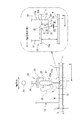
- FIG. 4 is an enlarged rear view (viewed from the rear) showing a lower portion of the slit nozzle 10.
- the coating apparatus further includes an air supply unit 21, which is provided on both outer sides in the width direction of the coating liquid L discharged from the discharge port 11. It has an air nozzle 22 that blows air to the vicinity area A.
- the air supply unit 21 includes a compressed air source (not shown), a control unit 23 having a function of adjusting the flow rate and pressure of the compressed air, and an air pipe 24. The control unit 23 controls the flow rate and pressure.
- Compressed air having been adjusted is supplied to the air nozzle 22 through the pipe 24, and the compressed air is injected from an air outlet 22 a formed at the tip of the air nozzle 22.
- the air jet port 22a has a diameter of 1 to 3 mm, and generates an air flow from the air jet port 22a (perpendicular to the air jet port 22a) in the direction of the arrow shown in FIGS.
- FIG. 4 shows only one side of the slit nozzle 10 in the width direction, but the other side has the same configuration.
- one side will be described.
- the air nozzle 22 is attached to a part of the slit nozzle 10 by the attachment member 25, the attachment position of the air nozzle 22 by this attachment member 25 can be changed in the width direction.
- the air pipe 24 is made of a flexible material and does not hinder the movement of the air nozzle 22. Thus, by changing the mounting position of the air nozzle 22, it is possible to adjust the air blowing position by the air nozzle 22.
- the width direction dimension (discharge width) of the discharge port 11 is changed by the discharge width changing member 17, so that the air nozzle 22 is separated from the slit nozzle 10 as a slit nozzle. 10 is installed by an attachment member 25, and the air blowing position is adjusted by the air nozzle 22 in accordance with the change in the width direction dimension of the discharge port 11 by the discharge width changing member 17.
- the position adjustment of the discharge width changing member 17 (the shaft 19) and the position adjustment of the air nozzle 22 may be performed manually by an operator, or may be performed by an actuator.
- the actuator performs, for example, the movement in the width direction of the discharge width changing member 17 and the movement in the width direction of the air nozzle 22 may be linked. That is, control is performed so that the movement amount of the position adjusting actuator of the air nozzle 22 and the position adjusting actuator of the discharge width changing member 17 are the same, thereby causing the discharge width changing member 17 and the air nozzle 22 to have the same stroke. Can be moved in the width direction.
- the air nozzle 22 supplies air to the vicinity area A on the outer side in the width direction of the coating liquid L (liquid bead formation area A0). Therefore, the air nozzle 22 is installed at a predetermined position. That is, the position of the air nozzle 22 in the width direction of the air ejection port 22a is, as shown in FIG. 4, the inner side surface 17a of the discharge width changing member 17 that defines the coating width B (more specifically, In the embodiment, it is a position slightly outside in the width direction with respect to a corner portion 31) described later.
- the front-rear direction position and the up-down direction position of the air outlet 22a are positions in the vicinity of the opening end 16a of the slit 16 (the front end of the air nozzle 22), as shown in FIG.
- the air injection direction that is, the center line of the air outlet 22a formed of a circular opening is a direction toward the space between the opening end 16a of the slit 16 and the substrate W, and is obliquely downward along the vertical plane. It is.
- the air outlet 22a of the air nozzle 22 has a center line on a virtual straight line Y that intersects with the substrate W after passing through the vicinity area A indicated by hatching in the partial enlarged view on the right side of FIG. ing.
- the vicinity area A is an area on both outer sides in the width direction of the coating liquid L (liquid bead formation area A 0 ) discharged from the discharge port 11 and extends from the substrate W to the opening end 11 a of the discharge port 11.
- This is a region having a height h corresponding to the clearance and a minute width k including the width k 0 in the front-rear direction at the opening end 16 a of the slit 16.
- the minute width k is a width obtained by combining the width of the lip tip surface 13a (the tip surface 13a of the rear lip 13 in FIG. 2) of the slit nozzle 10 on the side where the coating film S is formed and the width of the slit 16. (Dimension in the front-rear direction). That is, the minute width k is a width from the corner 13b on the side of the tip surface 13a where the coating film S is formed to the opening end 16a of the slit 16 (from which the coating film S is formed).
- a wall made of air is formed in the vicinity of the outer side in the width direction of the coating liquid L discharged from the discharge port 11, and the coating film S of the coating liquid L formed on the substrate W is formed by this wall. Can be prevented from spreading in the width direction, and variations in the width direction dimension of the coating film S can be suppressed.
- air can flow in the vicinity of both outer sides in the width direction of the coating liquid L placed on the substrate W, and the width of the coating liquid L by the dynamic pressure of the air. It is possible to reliably suppress the outward spread in the direction.
- the coating liquid L is caused by capillary action between the slit nozzle 10 and the substrate W in the enlarged view on the right side of FIG.
- What is necessary is just to enlarge P2a, and what is necessary is just to enlarge the flow velocity of the air from the air nozzle 22.
- the air flow is easily diffused, and the flow velocity is significantly reduced when the air flow is diffused. Therefore, in the present embodiment, in order to prevent the air from diffusing, an air flow in which the diffusion is small is generated by injecting the air from the fine air outlet 22a, and the dynamic pressure P2a should be generated.
- the contact area Q (see the partially enlarged view of FIG. 2) of the air jetted from the air jet port 22a and linearly traveling on the substrate W is within the range of the minute width k in the front-rear direction. Preferably there is. In the present embodiment, the entire contact region Q exists within the range of the minute width k. Then, the air blown onto the substrate W flows along the substrate W to generate a parallel flow.
- the position of the air ejection port 22a will be further described.
- the position of the jet port 22a is set such that the height from the lower end surface 10a is in the range of 1 mm to 3 mm, and the horizontal distance from the opening end 16a (on the nozzle 22 side) of the slit 16 is set in the range of 1 mm to 3 mm. Yes.
- the position of the air jet port 22a is set so that the direction of the air jetted linearly from the air jet port 22a is 40 degrees to 50 degrees with respect to the substrate W.
- the air nozzle 22 may be installed in a tilted direction with respect to the vertical plane.
- the air is injected toward the inner side in the width direction as shown by the two-dot chain line in FIG. 4 instead of being inclined in the direction of injecting the air toward the outer side in the width direction. It is preferable to incline in the direction.
- the air blowing position by the air nozzle 22 can be adjusted in accordance with the change in the width direction dimension of the discharge port 11 by the discharge width changing member 17 (change in the discharge width). Therefore, even if the discharge width is changed, the function of suppressing the variation in the dimension of the coating film S in the width direction by the air is maintained.
- the width direction dimension (coating width B) of the coating film S is set to the position of the discharge width changing member 17. It can be defined by adjustment and adjustment of the air blowing position by the air nozzle 22 of the air supply unit 21.
- the discharge width changing member 17 includes a protrusion 27 that protrudes toward the substrate W from the lower end surface 10 a where the discharge port 11 of the slit nozzle 10 is open.
- the projecting portion 27 has a central guide surface 28 that guides the coating liquid L that has flowed out of the slit 16 downward, and a lower surface that extends outward in the width direction from the lower end of the guide surface 28. 29 and an inclined surface 30 extending obliquely upward from the outer end in the width direction of the lower surface 29.
- the guide surface 28 is a vertical surface continuous with the inner surface 17a of the discharge width changing member 17, the lower surface 29 is a surface facing the substrate W, and the inclined surface 30 is the above-mentioned “outward in the width direction from the substrate W.
- the surface has a shape rounded up in the direction of separation.
- the reason why the width dimension (coating width B) of the coating film S by the coating liquid L applied on the substrate W fluctuates is that the characteristics (viscosity of the coating liquid L other than the coating liquid L spreading outward in the width direction). Etc.) or depending on the clearance between the lower end surface 10a where the discharge port 11 opens and the substrate W, the discharged coating liquid L becomes narrower in the width direction (the coating liquid L is pulled toward the center in the width direction). There is also. In this way, even under the condition that the coating liquid L tends to narrow inward in the width direction, the projecting portion 27 projects toward the substrate W, so that the coating liquid L is captured by the projecting portion 27 and the coating width. Fluctuation of B can be suppressed.
- the clearance between the lower surface 29 of the protruding portion 27 and the substrate W is narrower than the clearance between the lower end surface 10a of the slit nozzle 10 and the substrate W.
- the coating liquid is captured by the protrusions 27 due to capillary action between the two.
- the boundary part of this lower surface 29 and the inclined surface 30 consists of the corner
- the protrusion dimension m of the protrusion 27 from the lower end surface 10a is preferably as large as possible, and is changed by the clearance h.
- the protrusion dimension m is a dimension (clearance) from the lower end face 10a to the upper surface of the substrate W. h) to 10 to 40%.
- the protruding dimension m can be set to 0.1 to 0.3 mm.
- the dimension in the width direction n of the lower surface 29 is preferably large, for example, set to 0.1 to 10 mm.
- the inclination angle ⁇ of the inclined surface 30 with respect to the lower surface 29 (horizontal plane in the present embodiment) needs to be 30 ° or more, and is set to 30 to 90 °.
- the width direction dimension (application width B) of the coating film S is set to the ejection width. It can be defined by adjusting the position of the changing member 17. And when this coating device is also provided with the air supply unit 21, it can prescribe
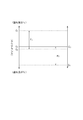
- FIG. 5 is an explanatory diagram for explaining the function of the discharge width variation suppressing mechanism for suppressing the variation in the coating width B.
- the clearance between the lower end surface 10a where the discharge port 11 is opened and the substrate W is precisely adjusted, the “spreading spread” and the “spreading narrowing” in which the coating liquid L spreads in the width direction can be suppressed. Is considered possible.
- the clearance in the case of thus precisely adjusted and C 0 of FIG.
- the clearance becomes non-uniform.
- the protruding portion 27 conditions the application liquid L is narrowed wet, in particular even when the clearance is wider than the C 0, the protruding portion 27 is protruded to the substrate W side Thus, the coating liquid L is captured by the protruding portion 27. Further, even when the coating liquid L is spread and spread, specifically, the clearance is narrower than C 0 , the protruding portion 27 has a shape that is rounded up in the direction away from the substrate W toward the outside in the width direction. Therefore, the spread of the coating liquid L can be effectively suppressed by the edge effect due to the shape. Thus, according to the protrusion 27, there is a margin in setting the clearance, and the clearance is set to C 1 to C 2 as shown in FIG.
- the range F1 can be set.
- the function of the protrusion 27 can effectively prevent the narrowing of the paint compared to the spread of the paint. Therefore, when the clearance is set to C 0 , the narrowing of the paint will be suppressed. The allowance for clearance adjustment increases.
- the coating apparatus conditions the application liquid L is spread wet, in particular even when the clearance is narrower than the C 0, according to the air supply unit 21, the discharge port 11
- the air can flow in the vicinity of both outer sides in the width direction of the coating liquid L discharged from the substrate and placed on the substrate W, and the spread of the coating liquid L can be effectively suppressed by the dynamic pressure of the air.
- the air supply unit 21 there is a margin in setting the clearance, and the clearance is set to C 3 to C as shown in FIG. 5 without setting the clearance to a strict value of C 0 .
- the range may be set to 4 range F2. In other words, when the clearance is set to C 0 as a reference, a margin for clearance adjustment in a direction to suppress spreading of spread increases.
- the effect of suppressing the spread of spreading is smaller than that of suppressing the narrowing of painting.
- the air supply unit 21 to function together with the protruding portion 27, the effect of suppressing spread of spread can be reinforced.
- the clearance margin is widened, the precise adjustment of the clearance becomes unnecessary, and the clearance varies due to the thickness of the substrate W being different in the surface direction. In addition, it is possible to suppress the fluctuation of the coating width B.
- the coating liquid has a width narrower than the entire width of the substrate W to be coated.
- the coating film S can be formed. That is, the coating liquid can be applied by making the width dimension of the discharge port 11 smaller than the entire width of the substrate W.
- the coating apparatus of the present invention includes one or both of the air supply unit 21 and the protruding portion 27 of the discharge width changing member 17 as a discharge width fluctuation suppressing mechanism that suppresses fluctuations in the coating width B.
- the discharge width changing member 17 may not have the protrusion 27, and only the air supply unit 21 may be provided as a discharge width variation suppressing mechanism.
- the air blowing position by the air nozzle 22 in this case will be described. From the viewpoint of ensuring the uniformity of the film thickness of the coating film S, the width direction dimension (discharge width) of the discharge port 11 and the coating width B coincide with each other.
- the coating width B is a corner portion 20a where the inner side surface 17a of the discharge width changing member 17 and the guide surface 20 (see the partially enlarged view on the right side of FIG. 4) facing the substrate W intersect.
- the air blowing position of the air nozzle 22 is adjusted so that the coating width B of the film S is defined.
- the coating apparatus of the present invention is not limited to the form shown in the drawings, and may be in another form within the scope of the present invention.
- the drive unit 4 of the present embodiment has been described as a mode in which the stage 3 holding the substrate W is moved forward with respect to the slit nozzle 10 in a fixed state on the base 1.
- the structure which moves the slit nozzle 10 with respect to the stage 3 in this may be sufficient. That is, the drive part 4 should just move the slit nozzle 10 and the board
- the air nozzle 22 is provided on the rear lip 13 side and the air is jetted toward the side opposite to the side on which the coating film S is formed in the front-rear direction.
- rip 12 side and injects air toward the side in which the coating film S is formed regarding the front-back direction may be sufficient.
Landscapes
- Coating Apparatus (AREA)
- Application Of Or Painting With Fluid Materials (AREA)
Abstract
L'invention concerne un dispositif de revêtement et une méthode de revêtement capable de supprimer les fluctuations de largeur d'un film de revêtement formé à partir d'un liquide de revêtement appliqué, tout en permettant de changer facilement la largeur de projection. En particulier, la présente invention comprend : une buse à fente (10) dotée d'un orifice de projection (11) comprenant une longue fente longitudinale (16) et qui projette un liquide de revêtement par l'orifice de projection (11) afin de revêtir un substrat (W) ; une unité d'entraînement (4) qui déplace le substrat (W) par rapport à la buse à fente (10) dans une direction aller-retour ; un élément de modification de largeur de projection (17) qui modifie la dimension en largeur de l'orifice de projection (11) en se déplaçant à l'intérieur de la fente (16) dans la direction latérale ; et une unité d'alimentation en air (21) qui comporte une buse d'air (22) qui pulvérise de l'air sur les régions des deux côtés latéraux extérieurs du liquide de revêtement projeté par l'orifice de projection (11) et qui est capable d'ajuster l'emplacement de la pulvérisation de l'air sortant de la buse d'air (22) correspondant aux modifications de la largeur de l'orifice de projection (11).
Applications Claiming Priority (2)
| Application Number | Priority Date | Filing Date | Title |
|---|---|---|---|
| JP2011047739A JP2012183469A (ja) | 2011-03-04 | 2011-03-04 | 塗布装置及び塗布方法 |
| JP2011-047739 | 2011-03-04 |
Publications (1)
| Publication Number | Publication Date |
|---|---|
| WO2012121026A1 true WO2012121026A1 (fr) | 2012-09-13 |
Family
ID=46797995
Family Applications (1)
| Application Number | Title | Priority Date | Filing Date |
|---|---|---|---|
| PCT/JP2012/054503 WO2012121026A1 (fr) | 2011-03-04 | 2012-02-24 | Dispositif de revêtement et méthode de revêtement |
Country Status (3)
| Country | Link |
|---|---|
| JP (1) | JP2012183469A (fr) |
| TW (1) | TW201244833A (fr) |
| WO (1) | WO2012121026A1 (fr) |
Cited By (1)
| Publication number | Priority date | Publication date | Assignee | Title |
|---|---|---|---|---|
| CN107812673A (zh) * | 2017-10-19 | 2018-03-20 | 苏州协鑫纳米科技有限公司 | 钙钛矿薄膜的涂布装置 |
Families Citing this family (2)
| Publication number | Priority date | Publication date | Assignee | Title |
|---|---|---|---|---|
| JP6824673B2 (ja) * | 2016-09-13 | 2021-02-03 | 株式会社Screenホールディングス | ノズル清掃部材、ノズル清掃装置、塗布装置 |
| JP6917329B2 (ja) * | 2018-03-22 | 2021-08-11 | 東レエンジニアリング株式会社 | 塗布装置 |
Citations (3)
| Publication number | Priority date | Publication date | Assignee | Title |
|---|---|---|---|---|
| JPH09131560A (ja) * | 1995-11-09 | 1997-05-20 | Toray Ind Inc | 塗布装置および塗布方法並びにカラーフィルタの製造装置および製造方法 |
| JPH1099764A (ja) * | 1996-08-07 | 1998-04-21 | Matsushita Electric Ind Co Ltd | 塗布装置及び方法 |
| JP2009220025A (ja) * | 2008-03-17 | 2009-10-01 | Fujifilm Corp | エクストルージョン塗布装置 |
-
2011
- 2011-03-04 JP JP2011047739A patent/JP2012183469A/ja not_active Withdrawn
-
2012
- 2012-02-21 TW TW101105572A patent/TW201244833A/zh unknown
- 2012-02-24 WO PCT/JP2012/054503 patent/WO2012121026A1/fr active Application Filing
Patent Citations (3)
| Publication number | Priority date | Publication date | Assignee | Title |
|---|---|---|---|---|
| JPH09131560A (ja) * | 1995-11-09 | 1997-05-20 | Toray Ind Inc | 塗布装置および塗布方法並びにカラーフィルタの製造装置および製造方法 |
| JPH1099764A (ja) * | 1996-08-07 | 1998-04-21 | Matsushita Electric Ind Co Ltd | 塗布装置及び方法 |
| JP2009220025A (ja) * | 2008-03-17 | 2009-10-01 | Fujifilm Corp | エクストルージョン塗布装置 |
Cited By (1)
| Publication number | Priority date | Publication date | Assignee | Title |
|---|---|---|---|---|
| CN107812673A (zh) * | 2017-10-19 | 2018-03-20 | 苏州协鑫纳米科技有限公司 | 钙钛矿薄膜的涂布装置 |
Also Published As
| Publication number | Publication date |
|---|---|
| JP2012183469A (ja) | 2012-09-27 |
| TW201244833A (en) | 2012-11-16 |
Similar Documents
| Publication | Publication Date | Title |
|---|---|---|
| TWI221098B (en) | Liquid spray applicator and liquid spray applicating method thereof | |
| KR20160115707A (ko) | 슬릿 노즐, 도포 방법, 및 도포 장치 | |
| WO2012121026A1 (fr) | Dispositif de revêtement et méthode de revêtement | |
| KR101357979B1 (ko) | 수지코팅막 성형장치의 코팅액 균일 분사노즐 | |
| JP4696690B2 (ja) | 溶融金属めっき鋼帯の製造方法 | |
| CN105983511A (zh) | 涂布装置和涂布方法 | |
| TW201940244A (zh) | 塗布器及塗布器之空氣排出方法 | |
| KR100828665B1 (ko) | 유체 분사노즐 | |
| US9457593B2 (en) | Liquid ejecting head, recording apparatus, and recording method | |
| US20150096492A1 (en) | Coating apparatus | |
| KR100901610B1 (ko) | 도포 장치 | |
| KR101357988B1 (ko) | 수지코팅막 성형장치의 진공 흡입에 의한 코팅막 안정화 기구 | |
| JPH06292854A (ja) | 液状塗膜剥取り装置 | |
| KR200494903Y1 (ko) | 갈바나이징 에어나이프의 노즐립 설치구조 | |
| KR20130092649A (ko) | 수지코팅막 성형장치의 분사간극 조절기구 | |
| US5824369A (en) | Method and apparatus for coating a traveling paper web | |
| KR20190019054A (ko) | 도포기 및 도포 장치 | |
| US5976251A (en) | Inlet for introducing water to wire edge guides for curtain coating | |
| JP2018001082A (ja) | 塗布装置及び塗布方法 | |
| JP2021023837A (ja) | 塗布ノズル及び塗布装置 | |
| JP7245047B2 (ja) | カーテンコータ | |
| JPH08196969A (ja) | 塗布ノズル | |
| JP2522871Y2 (ja) | ジェット式コーターヘッドの塗布幅調整装置 | |
| JP2013066866A (ja) | ダイコート塗工装置及び塗工方法 | |
| WO2013140620A1 (fr) | Enduiseuse à rideau |
Legal Events
| Date | Code | Title | Description |
|---|---|---|---|
| 121 | Ep: the epo has been informed by wipo that ep was designated in this application |
Ref document number: 12755237 Country of ref document: EP Kind code of ref document: A1 |
|
| NENP | Non-entry into the national phase |
Ref country code: DE |
|
| 122 | Ep: pct application non-entry in european phase |
Ref document number: 12755237 Country of ref document: EP Kind code of ref document: A1 |