WO2012120678A1 - Dispositif de thérapie par particules - Google Patents
Dispositif de thérapie par particules Download PDFInfo
- Publication number
- WO2012120678A1 WO2012120678A1 PCT/JP2011/055639 JP2011055639W WO2012120678A1 WO 2012120678 A1 WO2012120678 A1 WO 2012120678A1 JP 2011055639 W JP2011055639 W JP 2011055639W WO 2012120678 A1 WO2012120678 A1 WO 2012120678A1
- Authority
- WO
- WIPO (PCT)
- Prior art keywords
- irradiation
- particle beam
- dose
- accelerator
- spot
- Prior art date
Links
Images


Classifications
-
- A—HUMAN NECESSITIES
- A61—MEDICAL OR VETERINARY SCIENCE; HYGIENE
- A61N—ELECTROTHERAPY; MAGNETOTHERAPY; RADIATION THERAPY; ULTRASOUND THERAPY
- A61N5/00—Radiation therapy
- A61N5/10—X-ray therapy; Gamma-ray therapy; Particle-irradiation therapy
- A61N5/1042—X-ray therapy; Gamma-ray therapy; Particle-irradiation therapy with spatial modulation of the radiation beam within the treatment head
- A61N5/1043—Scanning the radiation beam, e.g. spot scanning or raster scanning
-
- A—HUMAN NECESSITIES
- A61—MEDICAL OR VETERINARY SCIENCE; HYGIENE
- A61N—ELECTROTHERAPY; MAGNETOTHERAPY; RADIATION THERAPY; ULTRASOUND THERAPY
- A61N5/00—Radiation therapy
- A61N5/10—X-ray therapy; Gamma-ray therapy; Particle-irradiation therapy
- A61N5/1048—Monitoring, verifying, controlling systems and methods
-
- A—HUMAN NECESSITIES
- A61—MEDICAL OR VETERINARY SCIENCE; HYGIENE
- A61N—ELECTROTHERAPY; MAGNETOTHERAPY; RADIATION THERAPY; ULTRASOUND THERAPY
- A61N5/00—Radiation therapy
- A61N5/10—X-ray therapy; Gamma-ray therapy; Particle-irradiation therapy
- A61N5/1077—Beam delivery systems
-
- A—HUMAN NECESSITIES
- A61—MEDICAL OR VETERINARY SCIENCE; HYGIENE
- A61N—ELECTROTHERAPY; MAGNETOTHERAPY; RADIATION THERAPY; ULTRASOUND THERAPY
- A61N5/00—Radiation therapy
- A61N5/10—X-ray therapy; Gamma-ray therapy; Particle-irradiation therapy
- A61N5/1048—Monitoring, verifying, controlling systems and methods
- A61N2005/1074—Details of the control system, e.g. user interfaces
-
- A—HUMAN NECESSITIES
- A61—MEDICAL OR VETERINARY SCIENCE; HYGIENE
- A61N—ELECTROTHERAPY; MAGNETOTHERAPY; RADIATION THERAPY; ULTRASOUND THERAPY
- A61N5/00—Radiation therapy
- A61N5/10—X-ray therapy; Gamma-ray therapy; Particle-irradiation therapy
- A61N2005/1085—X-ray therapy; Gamma-ray therapy; Particle-irradiation therapy characterised by the type of particles applied to the patient
- A61N2005/1087—Ions; Protons
Definitions
- the present invention relates to a particle beam therapy system using a charged particle beam, and more particularly to a particle beam therapy system using a scanning irradiation method.
- the affected area to be treated is irradiated with a charged particle beam (particle beam) to kill the affected tissue, and the surrounding tissue is not damaged.
- a particle beam therapy system capable of appropriately controlling the irradiation dose and the irradiation volume is required.
- the charged particle beam supplied from the accelerator is scanned while being positioned by a scanning electromagnet or the like, and predetermined for each small irradiation region (spot). Irradiation of dose is performed and an irradiation field is formed step by step.
- a charged particle beam is used until one slice is irradiated. Irradiate without blocking.
- the charged particle beam irradiation is turned on / off in synchronization with the respiration phase so that the organ can be irradiated only in a respiration state where the position of the organ is small and the position can be easily specified. It is necessary to turn it off.
- a beam blocking operation is performed at the end of irradiation of the final spot, which is the final time point of scanning irradiation in each slice, it is necessary to block the beam.
- a leakage dose is irradiated for a short period after the start of the blocking operation.
- JP2009-45170A (0020-0029, FIG. 1)
- the present invention has been made to solve the above-described problems, and an object of the present invention is to obtain a particle beam therapy system capable of suppressing the influence of a leakage dose.
- the particle beam therapy system of the present invention includes an accelerator that accelerates and emits a particle beam, and an irradiation nozzle that irradiates the particle beam emitted from the accelerator in a predetermined direction, having two electromagnets having different scanning directions.
- An irradiation control unit for controlling the operation of the irradiation nozzle so as to sequentially irradiate each of a plurality of spots set in the surface direction within the irradiation target with a predetermined dose of particle beam, and a particle beam from the accelerator
- a control unit that controls the ON / OFF of the emission of the irradiation, the irradiation control unit, for a predetermined period from when the emission of the particle beam is switched from ON to OFF, or until the beam is cut off,
- the irradiation nozzle is used to perform a scan (hereinafter referred to as a dilution scan) for diluting the leaked dose toward a predetermined range set in the surface direction within the irradiation target.
- the leakage dose during beam interruption is dispersed within a predetermined range of the irradiation target, so that an extra dose is emitted to a specific spot. Therefore, it is possible to give a dose closer to a treatment plan.
- FIG. 1 to 4 are diagrams for explaining the configuration and operation of the particle beam therapy system according to the first embodiment of the present invention.
- FIG. 1 is a diagram for explaining the overall configuration of the particle beam therapy system.
- FIG. 3 are figures which show the structure of the irradiation apparatus of a particle beam therapy apparatus.
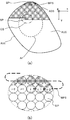
- FIG. 3 is a plan view of an irradiation target for explaining the canning irradiation method
- FIG. 3 (a) is a diagram showing the irradiation order in the entire irradiation target (total area)
- FIG. 3 (b) is FIG. 3 (a).
- FIG. 4 is a synchronized waveform diagram for explaining a charged particle beam control method.
- FIG. 4A is a gate signal based on respiratory synchronization control
- FIG. 4B is a beam that changes with the gate signal.
- FIG. 4 (c) shows the current irradiation spot and the deflection angles of the beam in the x and y directions by the scanning electromagnet for irradiating the spot.
- the feature of the particle beam therapy system according to the first embodiment of the present invention is that when the control for stopping the beam based on the respiratory phase occurs during the irradiation of a certain spot by the scanning irradiation method, the beam until the beam stops. Meanwhile, dilution scanning is performed so that the beam is swung within a predetermined range.
- the particle beam therapy system includes a circular accelerator 1 (hereinafter simply referred to as an accelerator) that is a synchrotron as a charged particle beam supply source, and an irradiation system including an irradiation device 2 provided for each treatment room 6.
- the accelerator 1 and each treatment room 6 are connected to each other, and a transport system 3 for transporting a charged particle beam from the accelerator to the irradiation device 2 of each treatment room 6 and a control system 4 for controlling these systems are provided. Next, the description will proceed to each configuration.
- the accelerator 1 includes a vacuum duct 11 serving as an orbital path around which the charged particle beam circulates, an incident device 12 for causing the charged particles supplied from the front-stage accelerator 5 to enter the vacuum duct 11, and an orbiting of the charged particles in the vacuum duct 11.
- Deflecting electromagnets 13a, 13b, 13c, 13d (collectively referred to as 13) for deflecting the trajectory of the charged particles so as to form a charged particle beam that circulates along the charged particle beam, and the charged particle beam formed on the circular trajectory diverges Convergence electromagnets 14a, 14b, 14c, and 14d (collectively referred to as 14) for converging, a high-frequency accelerating cavity 15 that accelerates by applying a high-frequency voltage synchronized with the circulating charged particles, and a charge accelerated in the accelerator 1
- a particle beam is taken out of the accelerator 1 and emitted to the transport system 3.
- the charged particle beam is emitted from the extraction device 16 and the extraction device 16.
- a sextupole electromagnet 17 to excite the resonance orbit of the charged particle beam in order.
- the deflection electromagnet 13 controls a deflection electromagnet controller that controls the excitation current of the deflection electromagnet 13, and the high-frequency acceleration cavity 15 controls a high-frequency source and a high-frequency source for supplying a high-frequency voltage to the high-frequency acceleration cavity 15.
- a device (not shown) for controlling each part is provided such as a high-frequency control device for controlling the entire accelerator 1 by controlling other components such as a deflection electromagnet control device, a high-frequency control device and a converging electromagnet 14.
- An accelerator control device (accelerator sub-controller 41 described later) and the like are also provided in the control unit 4.
- the front accelerator 5 is illustrated as a single device in the figure for the sake of simplicity, but in reality, an ion source (ion) that generates charged particles (ions) such as protons and carbon (heavy particles) ( Ion beam generator) and a linear accelerator system for initial acceleration of the generated charged particles.
- ion source ion
- Ion beam generator ion beam generator
- the charged particles incident on the accelerator 1 from the front stage accelerator 5 are accelerated by a high-frequency electric field and accelerated to about 70 to 80% of the speed of light while being bent by a magnet.
- the charged particle beam B accelerated by the accelerator 1 is emitted to a transport system 3 called a HEBT (High Energy Beam Transport) system.
- the transport system 3 includes a vacuum duct 31 that serves as a transport path for the charged particle beam B, a switching electromagnet 32 that is a switching device that switches the beam trajectory of the charged particle beam B, and a deflection electromagnet 33 that deflects the beam to a predetermined angle. ing.
- the charged particle beam B which is sufficiently energized by the accelerator 1 and travels in the vacuum duct 31, is transported by the switching electromagnet 32 as necessary (transport path 3A for the treatment room 6A, transport path 3B for the 6B,. ..
- the 6N transport route 3N) is changed and guided to the irradiation apparatus 2 provided for each designated treatment room 6.
- the irradiation system forms the irradiation field 2 according to the size and depth of the affected part TC of the patient K to be irradiated with the charged particle beam B supplied from the transport system 3 and irradiates the affected part, and respiratory synchronization
- the apparatus 7 is provided. Then, ON / OFF of irradiation to the affected part TC as an irradiation target is controlled in conjunction with respiration (in accordance with the phase of the respiration signal).
- the particle beam treatment apparatus generally has a plurality of treatment rooms (only treatment room 6A is shown in the figure, and treatment rooms 6B to 6N display only numbers. 6).
- the irradiation system shown here is one in which the irradiation device 2 and the respiratory synchronization device 7 are provided for each treatment room 6.
- the irradiation system for the treatment room 6A includes the irradiation device 2A and the respiratory synchronization device 7A. It is described as follows. The detailed configuration of the irradiation apparatus 2 will be described later, and the description of the entire particle beam therapy system will be continued.
- the respiratory synchronization device 7 has a partial function of a respiratory synchronization control unit that controls ON / OFF of emission of the charged particle beam B from the accelerator 1 in synchronization with the respiratory phase of the patient K. Therefore, the respiratory synchronization device 7 is configured to measure whether the respiratory state of the patient K is measured and whether or not the charged particle beam can be emitted from the accelerator 1 based on the actual respiratory waveform measured by the respiratory measurement device 71 (ON). / OFF) and a respiratory synchronizer body 70 for managing the entire respiratory synchronizer 7, and information relating to respiratory synchronization such as a target respiratory waveform and an actual respiratory waveform for inducing breathing. And a breathing information teaching device 72 for teaching a technician or the like.
- the treatment room 6 is a room for performing treatment by actually irradiating the patient K with the charged particle beam B, and basically includes the irradiation system described above for each treatment room.
- the irradiation apparatus 2A as a whole rotates from the deflection electromagnet 33G around the patient K (treatment table), and the rotation irradiation that allows the irradiation angle of the charged particle beam B to the patient K to be freely set.
- An example of a chamber also called a rotating gantry
- a horizontal irradiation chamber for irradiating a particle beam in a horizontal direction from an irradiation apparatus to a patient fixed on a treatment table whose angle and position can be freely set, and other types
- Control system As a control system of a system having a plurality of subsystems (accelerator 1, transport system 3, treatment room irradiation system, etc.) as described above, the sub-controller that controls each subsystem exclusively and the entire system are commanded and controlled. In many cases, a hierarchical control system composed of main controllers is used.
- the control unit 4 of the particle beam therapy system according to the first embodiment of the present invention also employs the configurations of the main controller and the sub controller. Functions that can be controlled in the subsystem are sub-controllers, and operations that control a plurality of systems in cooperation are controlled by the main controller.
- control unit 4 In the particle beam therapy system, a workstation or a computer is generally used for the control unit 4. Therefore, functions such as the main controller and the sub controller of the control unit 4 are expressed by software or the like, and do not always fit in specific hardware. Therefore, they are collectively described as the control unit 4 in the figure, but this does not mean that the control unit 4 physically exists as a single piece of hardware.
- a controller corresponding to the sub-controller of the irradiation apparatus 2 it is described as the sub-controller 42.
- the irradiation apparatus 2 in any direction substantially in the plane perpendicular to the beam B in the so-called pencil supplied via the transport system 3 from the accelerator 1 to the beam axis X B
- the scanning electromagnet 21 that functions as an irradiation nozzle for irradiation
- the ridge filter 22 for expanding the width of the Bragg peak according to the thickness of the irradiation target TC, and the depth (irradiation depth) of the irradiation target
- a range shifter 23 for changing the energy (range) of the charged particle beam B.
- xy plane perpendicular
- the ridge filter 22 is formed, for example, such that a large number of conical bodies and triangular plates having a triangular cross section are arranged in a plane, and if the inside of the irradiation spot is divided into a large number of small areas, the ridge filter 22 passes through different thicknesses for each small area. Charged particles are present.
- the cones are described as being arranged in a plane for easy understanding. Thereby, the width SOBP (Spread-Out Bragg Peak) of the Bragg peak is enlarged. That is, the ridge filter 22 widens the width in the depth direction where dose can be applied.
- the range shifter 23 is for attenuating the energy of the incident charged particle beam B by a predetermined amount.
- the range shifter 23 is provided with a plurality of resin plate materials having a predetermined thickness, and the attenuation amount is defined by a combination (total thickness) of the plate materials. can do.
- the affected part TC is divided so as to have a predetermined thickness in the depth direction. Then, as shown in FIG. 3, arranged irradiated area of the divided layers predetermined diameter with respect to (slice SS) per surface direction of the shape A SS (equivalent to the beam diameter) (spot SP) so as to fill without a gap, The dose for each spot SP and the irradiation route WPS are determined.
- Irradiation is basically performed from a layer (slice SS) including the deepest part of the affected part TC.
- the energy (range: reach depth) of the charged particle beam B irradiated from the irradiation device 2 is set in accordance with the depth of the slice SS1 at the deepest part.
- the energy is basically set by controlling the operation of the accelerator 1 via the sub-controller 41 in order to adjust the speed (kinetic energy) of the charged particle beam B emitted from the accelerator 1. Setting that is finer than the adjustment width is performed by the range shifter 23.
- the charged particle beam B which is adjusted in energy so as to have a predetermined range and supplied from the accelerator, is supplied to the irradiation device 2 as a so-called pencil beam having a diameter of about several millimeters through the transport system 3.
- the charged particle beam B supplied to the irradiation device 2 passes through the scanning electromagnet 21, a predetermined angle in the x direction (21 a) and the y direction (21 b) with respect to the beam axis X B according to the position of the spot SP.
- the irradiation direction is changed toward the spot SP.
- the charged particle beam B emitted toward the spot SP passes through the ridge filter 22, so that the SOBP is expanded so as to correspond to the thickness of the slice SS.
- the range shifter 23 that the projected range regulates dose is finely adjusted (beam current ⁇ time), for a given spot SP of the slice SS 1, the charged particle beam B of a predetermined dose can do.
- the process proceeds to irradiation of the next slice SS 2 .
- the energy of the charged particle beam B by the accelerator 1 and the range shifter 22, minutes lowered corresponding to the thickness of the slice SS projected range as (facing toward) is adjusted, the spot corresponding to the next slice SS 2 corresponding to the SP arrangement and illumination path WPS, scanning irradiation of the slice SS 2 is performed.
- the placement and illumination path of projected range and the spot SP in each slice SS j optimized dose to the shape of the affected part TC as a whole is given.
- the particle beam therapy system performs control in which raster scanning elements are incorporated in spot scanning irradiation. That is, in each slice SS, when sequentially irradiating while positioning from the first spot SP 1 to the last spot SP N according to the irradiation path WPS, the movement between the spots SP is irradiated with a beam like a raster scan. While moving at high speed. Generally, the number of spots SP ranging from several hundreds to several hundreds of thousands is assigned to one slice SS. However, if the charged particle beam B is interrupted every time it moves between the spots SP, it is blocked. This takes longer time and treatment time.
- the number of interruptions of the charged particle beam B in the slice SS without moving an extra dose to a portion other than the spot SP by moving between the spots SP while continuing irradiation at a high speed like a raster scan. Can be suppressed and the irradiation time can be reduced.
- FIG. 4A to FIG. 4C show the gate signal for instructing on / off of the beam, the beam current, and the deflection angle of the beam at this time.
- the vertical axis in FIG. 4A is a gate signal, the lower side is a state instructing the gate OFF that is beam blocking, and the upper side is the state instructing the beam ON that is beam irradiation.
- the vertical axis in FIG. 4B is a beam current indicating the amount of beam actually irradiated.
- FIG. 4C shows the irradiation target spot and the deflection angle of the beam for irradiating the irradiation spot. The deflection angle is divided into two vertical axes, and the upper vertical axis indicates the beam in the x direction.
- FIGS. 4A to 4C are synchronized time axes, the gate signal is switched from OFF to ON, and the point in time when the beam restart is instructed is T O , and the gate signal is switched from ON to OFF.
- the time point at which the switching is instructed to interrupt the beam is indicated by TF .
- the breathing synchronization apparatus main body 70 in the treatment room is a sub-controller 47 and functions as a part of the breathing synchronization control unit. If the sub-controller 47 functioning as a respiratory synchronization control unit determines that the respiratory phase of the patient K has become a phase in which the displacement of the affected part TC is large from the actual respiratory waveform measured by the respiratory measurement device 71, the sub-controller 47 turns off the irradiation. A power gate signal is output.
- the control unit 4 Upon receiving the gate signal, the control unit 4 (functioning as a respiratory synchronization device in cooperation with the sub-controller 47) outputs the charged particle beam B from the accelerator 1 to the sub-controller 41 for the accelerator 1 as a gate signal. Instructed to turn off (beam cutoff) in synchronization with Then, the charged particle beam B emitted from the accelerator 1 toward the irradiation device 2 is blocked.
- the beam current does not immediately become 0 at the switching time TF , and the beam current remains only for the period PL. .
- the integrated amount DL of the beam current in this period PL is irradiated from the irradiation apparatus 2 as a leakage dose.
- the deflection angle of the scanning electromagnet 21 is kept matched to the spot SP i , an extra dose of DL is irradiated to the spot SP i .
- the irradiation apparatus the second operation, towards the more limited the allowed area a P in the irradiation range a SS of the slice SS, switched so as to scan dilution.
- a sensor for observing the beam may be provided and continued until the beam is interrupted. That is, the operation of the scanning electromagnet 21 is controlled so that scanning is performed to dilute the leakage dose if the beam is emitted.
- the allowed area AP is set to an area having a certain area or more, for example, 100 times or more the spot diameter, and the leakage dose is diluted within the area.
- the operation of the scanning electromagnet 21 before and after the switching time TF will be described with reference to FIG.
- the irradiation target at the time when the gate signal is turned on is the spot SP i-3 .
- the spot SP i-2 , SP i-1 , SP i sequentially advances to the spot SP i.
- the gate signal is switched to OFF at a time point T F during the irradiation of.
- the position in the y direction does not change in SP i-3 to SP i as shown in FIG. 3B, so the y deflection angle basically shows a constant value.
- the deflection angle in the x direction and the deflection angle in the y direction change greatly.
- the change in the deflection angle is assumed assuming that a single-stroke path that repeatedly changes in the y direction while returning in the x direction is repeatedly scanned in the permitted area AP on a substantially ellipse, similarly to the path WPS. ing.
- the scanning electromagnet 21 is controlled so that the deflection angle corresponding to the spot SP i interrupted.
- the irradiation is surely performed at the deflection angle corresponding to the spot SP i and the subsequent irradiation is performed, and the irradiation at the spot SP i while the gate signal is turned on.
- the period can be adjusted appropriately.
- a beam blocking operation may be performed during irradiation of a certain spot SP by a gate signal, or a beam blocking operation may be performed immediately after completion of irradiation of the final spot SP at the final time point of each slice.
- scanning to distribute the authorization area A P having a predetermined area of the leakage radiation during blocking dose is diluted, concentrated dose a specific part The dose can be given in accordance with the treatment plan without doing so.
- the number of irradiation spots shown in one gate ON signal is four, but this is shown in a reduced number for explanation. Actually, irradiation with a larger number of spots is executed, and spots with different y directions in FIG. 3 are also irradiated. At this time, the deflection angle also changes according to the position in the y direction.
- the setting of the allowed area A P is not necessarily set to be narrower than the irradiation area A SS slices may be the same region.
- the fact that the gate signal is turned off indicates that the organ that is the irradiation target TC is more likely to be displaced. Therefore, in order to prevent unnecessary dose is applied to normal tissue surrounding the irradiation target TC, allowed area A P is preferably set inward margins than the irradiation area A SS.
- the margin amount or the permission area AP itself may be appropriately changed according to the displacement. Then, you need not include spots SP is irradiated with even T F time allowed area A P, may be separately set with spot SP.
- the route of dilution scanning in the allowed area A P are not necessarily the same as the path in the spot scanning, may be scanned diluted path of the spiral and other shapes.
- dilution scanning it is only necessary to perform scanning so as to fluctuate like so-called wobbler irradiation, but it is not necessary to make the dose distribution within the irradiation range uniform as in wobbler irradiation, and the dose is concentrated on a specific part. Do not do that.
- Such irradiation can be realized by controlling the scanning electromagnet 21 within a deflection angle range for forming a normal irradiation field. Therefore, the scanning electromagnet specifications can be changed, or a separate deflection electromagnet can be provided. do not have to. Furthermore, the amount of operation of the scanning electromagnet (distance angle opening) at the time of dilution scanning is basically within the range of the amount of operation at the time of normal irradiation. It does not occur and the scanning accuracy is not deteriorated. Further, the control unit 4 does not need to use special hardware if a sequence program for switching the operation to dilution scanning is added, for example.
- the dilution scan need not be limited when the beam is interrupted. For example, there beam current unstable period at the time T O resuming the beam, and, during the dose, when a degree that can be avoided affected by dilution, the diluted scan to cover the period You may apply. In this case, it is necessary to subtract the period for dilution scanning from the gate ON time when calculating the dose.
- the accelerator 1 that accelerates and emits the charged particle beam (particle beam) B and the two electromagnets 21a and 21b having different scanning directions are provided. and, a scanning electromagnet 21 which serves the particle beam B emitted from the accelerator 1 as irradiation nozzle for irradiating a predetermined direction, which is set in the treatment plan based on the irradiation target TC surface direction (in shape) in a SS of An irradiation control unit 42 (including the control unit 4) that controls the operation of the irradiation nozzle 21 so as to sequentially irradiate each of the plurality of spots SP with a predetermined dose of particle beam B while positioning, and breathing of the patient K
- a control unit 4 (and a sub-controller 47) that functions as a respiratory synchronization control unit that controls ON / OFF of the emission of the particle beam B from the accelerator 1 in synchronization with the phase.
- phase The surface direction in the irradiation object using the irradiation nozzle 21 until the particle beam B is cut off for a predetermined period PW from the time TF when the emission of the particle beam B is switched from ON to OFF in synchronization with (shape) toward a predetermined range a P set in the a SS to scan the particle beam B so as to dilute the leakage dose DL, since it is configured as breathing during irradiation of a certain spot SP or slice SS even if the synchronization beam blocking occurs due to, since the leakage dose DL in the beam blocking is diffused in the allowed area a P having a predetermined area in the irradiation object a SS, extra dose is given to a particular spot SP The dose can be given according to the treatment plan.
- the wobbler scanning within allowed area A P since it executes within the operating amount of the scanning electromagnet 21 to add an extra device, or to change the specification of the general scanning magnets for scanning irradiation There is no need.
- the particle beam trajectory is not bent outside the irradiation region, the leaked dose is not irradiated to the surrounding tissue outside the irradiation region.
- permission area A P took a predetermined margin from the irradiation area A SS considering a displacement of the organ is irradiated target TC, i.e. within a predetermined width in the planar direction (shape) A SS irradiation target TC If set, the leakage dose will not be given to normal tissue.
- the leakage dose is not given to the normal tissue moved by breathing.
- a time switch the P T F irradiation spot SP which has been subject can set the area of the dilution scanning in accordance with the spot, during blocking (dilution scanning) Switching from mode to normal (scanning irradiation) mode can be performed smoothly.
- the predetermined period PW for performing the dilution scan is determined based on the time P L required to stop the emission of the particle beam B from the time T F when the accelerator 1 is switched from ON to OFF, it can be dispersed and diluted to the dose DL reliably allowed area a P a.
- the irradiation nozzle 21 is set to the surface direction A SS within the irradiation target for a predetermined period PW from the time point T F when the emission of the particle beam is switched from ON to OFF in synchronization with the respiratory phase.
- a P is dispersed leakage dose DL in the a P predetermined range, but it is assumed that dilution, the scanning irradiation, in OFF the emission of the particle beam from the oN
- the switching operation is not limited to the case of synchronizing with the respiratory phase.
- the emission of the particle beam is switched from ON to OFF also at the end of irradiation of the final spot, which is the final scanning irradiation time in each slice SS.
- the leakage dose DL when the emission of the beam B is switched from ON to OFF at the end of irradiation of the final spot of each slice SS is within the permitted area AP . It is dispersed and diluted by scanning.
- scanning irradiation the spot SP arrangement, the irradiation path WPS, and the dose for each spot SP are determined in advance in the treatment plan for each slice SS.
- irradiation of the first spot SP 1 of the slice SS is performed according to the plan determined in the treatment plan.
- the next spot SP 2 is scanned.
- treatment plan is further scanned to the next spot SP 3.
- the dose of the last spot SP N reaches dose prescribed by the treatment plan, instructs the interruption of the beam B.
- the beam is not completely cut off at the time TF for instructing the beam to be cut off, and the beam current remains for the period PL, and the beam spot integration amount DL is the final spot.
- dose DL is given a leak in the SP N.
- the accelerator 1 that accelerates and emits the charged particle beam (particle beam) B and the two electromagnets 21a and 21b having different scanning directions are provided.
- the scanning electromagnet 21 that functions as an irradiation nozzle that irradiates the particle beam B emitted from the accelerator 1 in a predetermined direction, and a plurality of slices SS obtained by dividing the irradiation target TC in the depth direction based on the treatment plan, for each of a plurality of spots SP are set in the surface direction (in shape) in a SS of each slice SS, to sequentially irradiate the particle beam B of a predetermined dose while positioning, controls the operation of the irradiation nozzle 21 an irradiation control unit 42 (control unit 4 comprising a) the irradiation of the respective final spot SP N of the plurality of slices SS is completed, the control unit turns OFF the emission of the particle beam from the accelerator 1
- control unit 4 comprising a
- the wobbler scanning within allowed area A P since it executes within the operating amount of the scanning electromagnet 21 to add an extra device, or to change the specification of the general scanning magnets for scanning irradiation There is no need.
- the particle beam trajectory is not bent outside the irradiation region, the leaked dose is not irradiated to the surrounding tissue outside the irradiation region.
- the present invention is not specified only when the beam is interrupted as described in the first and second embodiments, but the leakage dose generated when the beam is interrupted during scanning irradiation is dispersed and diluted by dilution scanning. Needless to say, the present invention can also be applied to the case where the beam is interrupted due to other factors. Other factors include the following. When the safety interlock is activated due to device abnormalities such as beam intensity fluctuations or beam position fluctuations from the accelerator, or sudden changes in the patient's condition, and when the beam is interrupted once based on the treatment plan even within the same slice and so on.
- the accelerator 1 that accelerates and emits the charged particle beam (particle beam) B and the two electromagnets 21a and 21b having different scanning directions are included.
- the scanning electromagnet 21 that functions as an irradiation nozzle that irradiates the particle beam B emitted from the accelerator 1 in a predetermined direction, and each slice of a plurality of slices SS obtained by dividing the irradiation target TC in the depth direction, or the irradiation target TC of for each of the plurality of spots SP are set in the surface direction (in shape) in the a SS, to sequentially irradiate the particle beam B of a predetermined dose while positioning, irradiation control unit that controls the operation of the irradiation nozzle 21 42 (including the control unit 4) and the control unit 4 for turning off the emission of the particle beam from the accelerator 1, and the irradiation control unit 42 is configured to switch the emission of the particle beam B from ON
- the wobbler scanning within allowed area A P since it executes within the operating amount of the scanning electromagnet 21 to add an extra device, or to change the specification of the general scanning magnets for scanning irradiation There is no need.
- the particle beam trajectory is not bent outside the irradiation region, the leaked dose is not irradiated to the surrounding tissue outside the irradiation region.
- Embodiment 3 In the particle beam therapy system according to the first embodiment, a so-called leakage dose at the time of beam stop at the time of respiratory synchronous irradiation is scanned within a predetermined range, whereby the leakage dose is diluted to reduce the influence.
- a dose monitor is provided, and dose counting by the dose monitor is continued without stopping even when the beam is stopped, and the dose counted for each spot reaches a predetermined value. I moved to the next spot depending on whether or not. In other words, scanning irradiation is advanced based on whether or not the charged particle beam is interrupted, or based on the measured dose amount irradiated to the designated spot, not the irradiation time to the spot.
- FIG. 5 and 6 are for explaining the configuration and operation of the particle beam therapy system according to the third embodiment of the present invention.
- FIG. 5 is a diagram showing the configuration of the irradiation device of the particle beam therapy system.
- FIG. It is a flowchart for demonstrating the irradiation method in a particle beam therapy apparatus.
- the irradiation apparatus 202 includes a dose monitor 24 for measuring a beam dose, as in FIG. This is the same as the irradiation device 2 of the particle beam therapy system.
- no special operation control such as switching to dilution scanning is performed before and after the beam is cut off.
- each spot is based on a value obtained by integrating doses measured by the dose monitor 24. It is characterized by controlling the irradiation.
- a slice SS number to be scanned first is set (step S10, step S20). Then, the position of the irradiation range A SS and the spots SP in response to the slice SS, route and dose, set other irradiation conditions (step S30).
- the scanning electromagnet 21 controls the deflection angle corresponding to each target spot SP
- the dose at the spot SP starts to be integrated based on the measurement value from the dosimeter 24 (steps S40 to S60). If the integrated value D of the measured dose has not reached the set value (“N” in step S70), the state in which the deflection angle is controlled at the spot SP is maintained.
- the process proceeds to the next spot SP (step S40). If the spot SP is the final spot (“Y” in step S80), it is determined whether or not it is the final slice. If it is not the final slice SS (“N” in step S90), the process proceeds to the next slice SS (step S20), and the same operation is repeated. If it is the last slice SS (“Y” in step S90), the irradiation is terminated.
- the dose given to each spot is irradiated so that it matches the set value specified in the treatment plan. Can do.
- safety measures such as stopping the irradiation by operating an interlock may be taken.
Landscapes
- Health & Medical Sciences (AREA)
- Engineering & Computer Science (AREA)
- Biomedical Technology (AREA)
- Pathology (AREA)
- Nuclear Medicine, Radiotherapy & Molecular Imaging (AREA)
- Radiology & Medical Imaging (AREA)
- Life Sciences & Earth Sciences (AREA)
- Animal Behavior & Ethology (AREA)
- General Health & Medical Sciences (AREA)
- Public Health (AREA)
- Veterinary Medicine (AREA)
- Radiation-Therapy Devices (AREA)
Abstract
Priority Applications (5)
| Application Number | Priority Date | Filing Date | Title |
|---|---|---|---|
| CN201180053865.9A CN103200993B (zh) | 2011-03-10 | 2011-03-10 | 粒子射线治疗装置 |
| PCT/JP2011/055639 WO2012120678A1 (fr) | 2011-03-10 | 2011-03-10 | Dispositif de thérapie par particules |
| JP2013503302A JP5496414B2 (ja) | 2011-03-10 | 2011-03-10 | 粒子線治療装置 |
| US13/258,772 US8421031B2 (en) | 2011-03-10 | 2011-03-10 | Particle beam therapy system |
| EP11860475.0A EP2684580B1 (fr) | 2011-03-10 | 2011-03-10 | Dispositif de thérapie par particules |
Applications Claiming Priority (1)
| Application Number | Priority Date | Filing Date | Title |
|---|---|---|---|
| PCT/JP2011/055639 WO2012120678A1 (fr) | 2011-03-10 | 2011-03-10 | Dispositif de thérapie par particules |
Publications (1)
| Publication Number | Publication Date |
|---|---|
| WO2012120678A1 true WO2012120678A1 (fr) | 2012-09-13 |
Family
ID=46794682
Family Applications (1)
| Application Number | Title | Priority Date | Filing Date |
|---|---|---|---|
| PCT/JP2011/055639 WO2012120678A1 (fr) | 2011-03-10 | 2011-03-10 | Dispositif de thérapie par particules |
Country Status (5)
| Country | Link |
|---|---|
| US (1) | US8421031B2 (fr) |
| EP (1) | EP2684580B1 (fr) |
| JP (1) | JP5496414B2 (fr) |
| CN (1) | CN103200993B (fr) |
| WO (1) | WO2012120678A1 (fr) |
Cited By (2)
| Publication number | Priority date | Publication date | Assignee | Title |
|---|---|---|---|---|
| JP2017086868A (ja) * | 2015-11-11 | 2017-05-25 | 三菱電機株式会社 | 粒子線照射装置 |
| JP2017209579A (ja) * | 2017-09-11 | 2017-11-30 | 住友重機械工業株式会社 | 荷電粒子線治療装置、及び荷電粒子線治療装置の制御方法 |
Families Citing this family (16)
| Publication number | Priority date | Publication date | Assignee | Title |
|---|---|---|---|---|
| JP5784824B2 (ja) * | 2012-04-19 | 2015-09-24 | 三菱電機株式会社 | ガントリー型粒子線照射装置、およびこれを備えた粒子線治療装置 |
| US9333374B2 (en) * | 2012-11-20 | 2016-05-10 | Mitsubishi Electric Corporation | Treatment planning device, particle beam therapy system and method for determining scanning route of charged particle beam |
| WO2014102929A1 (fr) * | 2012-12-26 | 2014-07-03 | 三菱電機株式会社 | Dispositif de mesure de la répartition de doses |
| CN105142723A (zh) * | 2013-04-23 | 2015-12-09 | 三菱电机株式会社 | 粒子射线治疗装置及其运行方法 |
| US8964937B2 (en) * | 2013-05-17 | 2015-02-24 | Elekta Ab (Publ) | Methods and systems in radiotherapy |
| JP6109702B2 (ja) * | 2013-10-15 | 2017-04-05 | 住友重機械工業株式会社 | 荷電粒子線照射装置 |
| US9789342B2 (en) * | 2015-05-18 | 2017-10-17 | Varian Medical Systems, Inc. | System and method for in-layer synchronization for fast spot rescanning |
| CN105251138B (zh) * | 2015-11-13 | 2018-03-13 | 上海艾普强粒子设备有限公司 | 一种粒子照射装置以及包括该装置的粒子治疗系统 |
| CN105797282B (zh) * | 2016-03-07 | 2018-09-04 | 上海艾普强粒子设备有限公司 | 一种粒子照射装置以及包括该装置的粒子治疗系统 |
| US10661100B2 (en) * | 2017-03-08 | 2020-05-26 | Mayo Foundation For Medical Education And Research | Method for measuring field size factor for radiation treatment planning using proton pencil beam scanning |
| CN109224317B (zh) * | 2017-07-11 | 2022-02-18 | 住友重机械工业株式会社 | 带电粒子束治疗装置 |
| JP6901381B2 (ja) * | 2017-11-20 | 2021-07-14 | 株式会社日立製作所 | 加速器および粒子線治療システム |
| CN108969904B (zh) * | 2018-06-06 | 2021-05-28 | 清华大学 | 一种用于肿瘤放射治疗的心肺运动门控设备及系统 |
| JP7160716B2 (ja) * | 2019-02-18 | 2022-10-25 | 株式会社日立製作所 | 粒子線治療装置及びその作動方法 |
| JP7430044B2 (ja) * | 2019-09-17 | 2024-02-09 | 住友重機械工業株式会社 | 放射線治療装置 |
| CN113952636B (zh) * | 2020-07-20 | 2023-08-08 | 中硼(厦门)医疗器械有限公司 | 放射治疗系统及其安全联锁控制方法 |
Citations (5)
| Publication number | Priority date | Publication date | Assignee | Title |
|---|---|---|---|---|
| JP2006145213A (ja) * | 2004-11-16 | 2006-06-08 | Hitachi Ltd | 粒子線照射システム |
| JP2007311125A (ja) * | 2006-05-17 | 2007-11-29 | Mitsubishi Electric Corp | 荷電粒子ビーム加速器のビーム出射制御方法及び荷電粒子ビーム加速器を用いた粒子ビーム照射システム |
| JP2009045170A (ja) | 2007-08-17 | 2009-03-05 | Hitachi Ltd | 粒子線治療システム |
| JP2009066106A (ja) * | 2007-09-12 | 2009-04-02 | Toshiba Corp | 粒子線ビーム照射装置および粒子線ビーム照射方法 |
| JP2011000378A (ja) * | 2009-06-22 | 2011-01-06 | Hitachi Ltd | 荷電粒子ビーム照射システム |
Family Cites Families (6)
| Publication number | Priority date | Publication date | Assignee | Title |
|---|---|---|---|---|
| JPH10155922A (ja) | 1996-11-29 | 1998-06-16 | Hitachi Medical Corp | 放射線治療装置 |
| JPH10277170A (ja) | 1997-04-08 | 1998-10-20 | Hitachi Medical Corp | 放射線治療装置 |
| WO2008055506A2 (fr) * | 2006-11-10 | 2008-05-15 | Lars Michael Larsen | Procédé et appareil de photomanipulation peu ou pas perturbante pour l'oeil |
| JP4877784B2 (ja) | 2006-11-30 | 2012-02-15 | 独立行政法人放射線医学総合研究所 | 照射計画装置、粒子線照射システム、及び、これらに用いるコンピュータプログラム |
| JP4988516B2 (ja) * | 2007-11-06 | 2012-08-01 | 株式会社日立製作所 | 粒子線治療システム |
| JP5074915B2 (ja) * | 2007-12-21 | 2012-11-14 | 株式会社日立製作所 | 荷電粒子ビーム照射システム |
-
2011
- 2011-03-10 JP JP2013503302A patent/JP5496414B2/ja active Active
- 2011-03-10 WO PCT/JP2011/055639 patent/WO2012120678A1/fr active Application Filing
- 2011-03-10 US US13/258,772 patent/US8421031B2/en active Active
- 2011-03-10 EP EP11860475.0A patent/EP2684580B1/fr not_active Not-in-force
- 2011-03-10 CN CN201180053865.9A patent/CN103200993B/zh not_active Expired - Fee Related
Patent Citations (5)
| Publication number | Priority date | Publication date | Assignee | Title |
|---|---|---|---|---|
| JP2006145213A (ja) * | 2004-11-16 | 2006-06-08 | Hitachi Ltd | 粒子線照射システム |
| JP2007311125A (ja) * | 2006-05-17 | 2007-11-29 | Mitsubishi Electric Corp | 荷電粒子ビーム加速器のビーム出射制御方法及び荷電粒子ビーム加速器を用いた粒子ビーム照射システム |
| JP2009045170A (ja) | 2007-08-17 | 2009-03-05 | Hitachi Ltd | 粒子線治療システム |
| JP2009066106A (ja) * | 2007-09-12 | 2009-04-02 | Toshiba Corp | 粒子線ビーム照射装置および粒子線ビーム照射方法 |
| JP2011000378A (ja) * | 2009-06-22 | 2011-01-06 | Hitachi Ltd | 荷電粒子ビーム照射システム |
Non-Patent Citations (1)
| Title |
|---|
| See also references of EP2684580A4 |
Cited By (2)
| Publication number | Priority date | Publication date | Assignee | Title |
|---|---|---|---|---|
| JP2017086868A (ja) * | 2015-11-11 | 2017-05-25 | 三菱電機株式会社 | 粒子線照射装置 |
| JP2017209579A (ja) * | 2017-09-11 | 2017-11-30 | 住友重機械工業株式会社 | 荷電粒子線治療装置、及び荷電粒子線治療装置の制御方法 |
Also Published As
| Publication number | Publication date |
|---|---|
| EP2684580A1 (fr) | 2014-01-15 |
| US20120228521A1 (en) | 2012-09-13 |
| EP2684580B1 (fr) | 2015-08-26 |
| US8421031B2 (en) | 2013-04-16 |
| EP2684580A4 (fr) | 2014-09-10 |
| JP5496414B2 (ja) | 2014-05-21 |
| CN103200993A (zh) | 2013-07-10 |
| JPWO2012120678A1 (ja) | 2014-07-07 |
| CN103200993B (zh) | 2015-10-07 |
Similar Documents
| Publication | Publication Date | Title |
|---|---|---|
| JP5496414B2 (ja) | 粒子線治療装置 | |
| JP5133319B2 (ja) | 粒子線照射システムおよびその制御方法 | |
| JP5002612B2 (ja) | 荷電粒子ビーム照射装置 | |
| JP5896211B2 (ja) | 荷電粒子照射システムおよび荷電粒子照射システムの作動方法 | |
| JP2009148473A (ja) | 荷電粒子ビーム照射システム | |
| JP2006145213A (ja) | 粒子線照射システム | |
| JP4726869B2 (ja) | 荷電粒子ビーム照射システム及びその制御方法 | |
| JP4864787B2 (ja) | 粒子線照射システムおよびその制御方法 | |
| JP5705372B2 (ja) | 粒子線治療装置および粒子線治療装置の運転方法 | |
| CN108348767B (zh) | 粒子束治疗系统 | |
| WO2014030207A1 (fr) | Dispositif de commande pour électro-aimant de balayage et appareil de thérapie par faisceau de particules | |
| JP2017209372A (ja) | 荷電粒子線治療装置 | |
| JP2009072287A (ja) | 粒子線照射装置 | |
| JP2010075584A (ja) | 粒子線照射システム及びこの制御方法 | |
| TWI537023B (zh) | 粒子線治療裝置 | |
| JP5396517B2 (ja) | 粒子線照射システム | |
| TWI681794B (zh) | 帶電粒子束治療裝置 | |
| JP2011206495A (ja) | 粒子線治療システム | |
| WO2019198211A1 (fr) | Dispositif de traitement par faisceau de particules chargées | |
| JP6815231B2 (ja) | 荷電粒子線治療装置 | |
| JP7165499B2 (ja) | 荷電粒子線治療装置 | |
| US10381195B2 (en) | Charged particle beam treatment apparatus | |
| WO2016104040A1 (fr) | Dispositif à rayonnement de faisceau de particules et procédé de commande de dispositif à rayonnement de faisceau de particules |
Legal Events
| Date | Code | Title | Description |
|---|---|---|---|
| WWE | Wipo information: entry into national phase |
Ref document number: 13258772 Country of ref document: US |
|
| 121 | Ep: the epo has been informed by wipo that ep was designated in this application |
Ref document number: 11860475 Country of ref document: EP Kind code of ref document: A1 |
|
| ENP | Entry into the national phase |
Ref document number: 2013503302 Country of ref document: JP Kind code of ref document: A |
|
| WWE | Wipo information: entry into national phase |
Ref document number: 2011860475 Country of ref document: EP |
|
| NENP | Non-entry into the national phase |
Ref country code: DE |