WO2012118167A1 - Raccord fileté pour tube - Google Patents
Raccord fileté pour tube Download PDFInfo
- Publication number
- WO2012118167A1 WO2012118167A1 PCT/JP2012/055292 JP2012055292W WO2012118167A1 WO 2012118167 A1 WO2012118167 A1 WO 2012118167A1 JP 2012055292 W JP2012055292 W JP 2012055292W WO 2012118167 A1 WO2012118167 A1 WO 2012118167A1
- Authority
- WO
- WIPO (PCT)
- Prior art keywords
- pin
- seal
- nose
- box
- screw
- Prior art date
Links
- 230000008878 coupling Effects 0.000 title claims abstract description 5
- 238000010168 coupling process Methods 0.000 title claims abstract description 5
- 238000005859 coupling reaction Methods 0.000 title claims abstract description 5
- 230000002093 peripheral effect Effects 0.000 claims abstract description 19
- 239000002184 metal Substances 0.000 claims description 9
- 229910000831 Steel Inorganic materials 0.000 abstract description 12
- 239000010959 steel Substances 0.000 abstract description 12
- 230000006835 compression Effects 0.000 description 27
- 238000007906 compression Methods 0.000 description 27
- 238000007789 sealing Methods 0.000 description 18
- 238000012360 testing method Methods 0.000 description 16
- 238000000034 method Methods 0.000 description 4
- 238000005452 bending Methods 0.000 description 3
- 238000002474 experimental method Methods 0.000 description 3
- 239000003921 oil Substances 0.000 description 3
- 239000003129 oil well Substances 0.000 description 3
- 230000000052 comparative effect Effects 0.000 description 2
- 238000013461 design Methods 0.000 description 2
- 238000009826 distribution Methods 0.000 description 2
- 239000007789 gas Substances 0.000 description 2
- 238000004519 manufacturing process Methods 0.000 description 2
- VNWKTOKETHGBQD-UHFFFAOYSA-N methane Chemical compound C VNWKTOKETHGBQD-UHFFFAOYSA-N 0.000 description 2
- OCKGFTQIICXDQW-ZEQRLZLVSA-N 5-[(1r)-1-hydroxy-2-[4-[(2r)-2-hydroxy-2-(4-methyl-1-oxo-3h-2-benzofuran-5-yl)ethyl]piperazin-1-yl]ethyl]-4-methyl-3h-2-benzofuran-1-one Chemical compound C1=C2C(=O)OCC2=C(C)C([C@@H](O)CN2CCN(CC2)C[C@H](O)C2=CC=C3C(=O)OCC3=C2C)=C1 OCKGFTQIICXDQW-ZEQRLZLVSA-N 0.000 description 1
- 235000010676 Ocimum basilicum Nutrition 0.000 description 1
- 240000007926 Ocimum gratissimum Species 0.000 description 1
- 239000010779 crude oil Substances 0.000 description 1
- 238000011161 development Methods 0.000 description 1
- 238000005553 drilling Methods 0.000 description 1
- 238000005461 lubrication Methods 0.000 description 1
- 238000003754 machining Methods 0.000 description 1
- 239000000463 material Substances 0.000 description 1
- 239000003345 natural gas Substances 0.000 description 1
- 239000003208 petroleum Substances 0.000 description 1
Images


Classifications
-
- F—MECHANICAL ENGINEERING; LIGHTING; HEATING; WEAPONS; BLASTING
- F16—ENGINEERING ELEMENTS AND UNITS; GENERAL MEASURES FOR PRODUCING AND MAINTAINING EFFECTIVE FUNCTIONING OF MACHINES OR INSTALLATIONS; THERMAL INSULATION IN GENERAL
- F16L—PIPES; JOINTS OR FITTINGS FOR PIPES; SUPPORTS FOR PIPES, CABLES OR PROTECTIVE TUBING; MEANS FOR THERMAL INSULATION IN GENERAL
- F16L15/00—Screw-threaded joints; Forms of screw-threads for such joints
- F16L15/001—Screw-threaded joints; Forms of screw-threads for such joints with conical threads
-
- E—FIXED CONSTRUCTIONS
- E21—EARTH OR ROCK DRILLING; MINING
- E21B—EARTH OR ROCK DRILLING; OBTAINING OIL, GAS, WATER, SOLUBLE OR MELTABLE MATERIALS OR A SLURRY OF MINERALS FROM WELLS
- E21B17/00—Drilling rods or pipes; Flexible drill strings; Kellies; Drill collars; Sucker rods; Cables; Casings; Tubings
- E21B17/02—Couplings; joints
- E21B17/04—Couplings; joints between rod or the like and bit or between rod and rod or the like
- E21B17/042—Threaded
-
- F—MECHANICAL ENGINEERING; LIGHTING; HEATING; WEAPONS; BLASTING
- F16—ENGINEERING ELEMENTS AND UNITS; GENERAL MEASURES FOR PRODUCING AND MAINTAINING EFFECTIVE FUNCTIONING OF MACHINES OR INSTALLATIONS; THERMAL INSULATION IN GENERAL
- F16L—PIPES; JOINTS OR FITTINGS FOR PIPES; SUPPORTS FOR PIPES, CABLES OR PROTECTIVE TUBING; MEANS FOR THERMAL INSULATION IN GENERAL
- F16L15/00—Screw-threaded joints; Forms of screw-threads for such joints
- F16L15/06—Screw-threaded joints; Forms of screw-threads for such joints characterised by the shape of the screw-thread
Definitions
- the present invention relates to a threaded joint for steel pipe, and specifically includes tubing and casing generally used for exploration and production of oil wells and gas wells. Sealability and compression resistance suitable for connecting steel pipes such as OCTG (oil country tubular goods), riser pipes, line pipes, etc.
- the present invention relates to a threaded joint for pipes having excellent resistance.
- Threaded joints are widely used to connect steel pipes used in oil industry equipment such as oil well pipes.
- API American Petroleum Institute
- standard threaded joints specified in the API have been typically used to connect steel pipes used for searching and producing oil and gas.
- wells for crude oil and natural gas have been deepened, and vertical wells, horizontal wells, gradient wells, etc. have increased. For this reason, the drilling and production environment has become severe.
- compression resistance, bending resistance, external pressure seal performance (External pressure resistance) )) Etc. the required performance for threaded joints is diversifying. Therefore, the use of high-performance special thread joints (premium joints) called premium joints is increasing, and the demand for performance is also increasing.
- Premium joints usually have a tapered thread, a seal part (specifically a metal touch seal part), a shoulder part (specifically, a torque shoulder part, and more specifically a torque shoulder part).
- a male screw member (externally-threaded member) (hereinafter referred to as a pin) formed on the end of the tube and an internally-threaded member (hereinafter referred to as a box) for connecting the pins to each other.
- a coupling type coupling is important for firmly fixing the pipe joint, and the seal part plays a role of ensuring the sealing performance by metal contact between the box and the pin at this part, and the shoulder part is a stopper ( It becomes a shoulder surface (bearing face) that plays the role of an abutment.
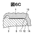
- FIG. 6A to FIG. 6C are schematic explanatory views of a conventional premium joint for oil well pipes, and these are longitudinal sectional views of a threaded joint of a circular pipe.
- the screw joint of FIG. 6A includes a pin 3 and a box 1 corresponding to the pin 3.
- the pin 3 has a male screw portion 7 on its outer surface and a tip end side of the pin 3.
- It has the nose part (pin nose (pin nose) 8) which is the length part without a screw
- the nose portion 8 has a seal portion 11 on its outer peripheral surface and a torque shoulder portion 12 on its end surface.
- the opposing box 1 has a female screw part 5, a seal part 13, and a part that can be screwed or brought into contact with the male screw part 7, the seal part 11, and the shoulder part 12 of the pin 3, respectively. And it has the shoulder part 14.
- Patent document 1 is mentioned as a prior art regarding the said premium joint.
- the seal portion is at the tip portion of the pin nose 8, and a desired sealing performance can be realized by applying an appropriate tightening torque (make up torque). Since the tightening torque is affected by lubrication conditions, surface properties, etc., there is a radial seal method in which the radial component of the seal contact pressure is relatively strong as a design that does not depend greatly on this.
- Patent Document 1 discloses an example of a radial seal method having a large pin seal R shape and a small seal taper angle.
- the problem with the radial seal method in which the seal taper angle is reduced in this way is that galling is likely to occur during tightening, and in particular for the purpose of ensuring sealing performance and sealing stability.
- the interference amount (seal interference amount) is increased, the ease of occurrence of goling is significantly increased.
- a necessary and sufficient contact pressure is applied to the seal portions 11 and 13 in FIG. 6C or the seal portion of the radial seal method (hereinafter also referred to as a radial seal type).
- a healthy seal portion free from leaks or goling is formed.
- the rigidity of the pin nose 8 is important for ensuring the sealing performance of the radial seal type, and the seal point sp (see FIG.
- the inventors have found a guideline for making the ratio of the cross-sectional area of the pin at the seal point sp and the cross-sectional area of the unprocessed part appropriate. Furthermore, the inventors set the axial compression force load at the seal point sp of the pin by setting the angle formed by the straight line connecting the position of the seal point sp and the lower end of the pin shoulder to the joint axial direction in the pipe axial direction cross section. It has been found that it is possible to reduce the deformation of the time and ensure the sealing performance. That is, the present invention is as follows.
- a pin having a male screw part, a nose part extending from the male screw part to the tube end side, and a shoulder part provided at the tip of the nose part;
- a female screw part that is screw-coupled with the male screw part to form a screw part, a seal surface that faces the outer peripheral surface of the nose part of the pin, and a box that has a shoulder part that contacts the shoulder part of the pin, a metal contact (metal to metal contact) basil be pipe thread fittings, such contact portion is the seal portion of - the pin and the box and is coupled with said sealing surface of said nose portion outer peripheral surface and the box pins metal by a screw connection
- the outer peripheral surface of the nose portion on the pin side is a curved surface shape convex outward
- the seal surface on the box side is a tapered shape
- the raw tube portion in which the cross-sectional area of the pin at the seal point, which is the portion on the outer peripheral surface of the nose portion on the pin side that first comes into contact with the sealing surface on the box side during the
- the rigidity of the pin nose is improved, and even when a large axial compression force is applied, the pin outer diameter is less likely to be reduced due to compression and bending deformation, and a threaded joint for steel pipe that can ensure excellent sealing performance is realized. . Furthermore, by setting the seal point at an appropriate position, even if the pin outer diameter is reduced due to the axial compression force, excellent sealing performance can be ensured by suppressing the influence on the seal portion.
- FIG. 2 is an enlarged cross-sectional view illustrating the shape of the seal portion of FIG. 1 together with definitions of a seal taper angle ⁇ and an interference amount ⁇ .
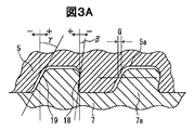
- FIG. 3A is a cross-sectional view illustrating definitions of a load flank angle (load) ⁇ , a stubbing flank angle ⁇ , and a gap G of a threaded portion.
- FIG. 3B is a cross-sectional view showing the definition of the position index (positional index) x / L of the seal point sp.
- the threaded joint for pipes includes, as shown in FIG. 1 and FIG. 2, for example, a sectional view in the axial direction of the joint, a male thread part 7, a nose part 8 extending from the male thread part 7 to the pipe end side, and the nose A pin 3 having a shoulder portion 12 provided at the tip of the portion 8, a female screw portion 5 screwed to the male screw portion 7 to form a screw portion, and a seal surface facing the outer peripheral surface of the nose portion of the pin 3; And a box 1 having a shoulder portion 14 that abuts the shoulder portion 12 of the pin 3, and the threaded joint is connected to the pin 3 and the box 1 by the nose portion of the pin 3.
- the contact portion is a threaded joint for pipes forming the seal portion 20 (the seal taper angle ⁇ of the box 1 is not less than 3 degrees and not more than 10 degrees) Conventional It is radial seal type premium joint equivalent of the threaded joint) assuming a.
- the load flank angle ⁇ is an angle ⁇ formed by the load flank surface 18 with respect to the orthogonal line to the threaded joint axis, and when the orthogonal line passes through the lower end (end on the inner diameter side of the pin) of the load flank surface, the orthogonal line
- ⁇ ⁇ 10 degrees to 0 degrees.
- the stubbing flank angle ⁇ is an angle ⁇ formed by the stubbing flank surface 19 with respect to the orthogonal line to the threaded joint axis, and when the orthogonal line passes through the lower end (end on the inner diameter side of the pin) of the stubbing flank surface, When the upper end (end on the pin outer diameter side) of the stubbing flank is located on the tip end side of the pin with respect to the orthogonal line, it is negative.
- ⁇ 10 degrees to 30 degrees.
- the gap G of the thread portion is a gap G between the thread 7a of the male thread and the thread groove 5a of the female thread that meshes with the thread 7a.
- G 0.025 to 0.250 mm.
- the outer peripheral surface of the nose portion on the pin 3 side is an outwardly convex curved surface shape
- the seal surface on the box 1 side is a tapered shape.
- the taper angle ⁇ of the taper surface forming the taper shape is defined as an angle ⁇ formed by the taper surface with respect to the threaded joint axis.
- the seal point sp is a portion on the outer peripheral surface of the nose portion on the pin 3 side that first contacts the seal surface on the box 1 side during screw connection.
- the relative position of the seal point sp in the axial direction of the threaded joint is the thread portion with respect to the length (nose length) L of the nose portion 8 from the tip of the screw portion (the rear end of the nose portion) to the tip of the nose portion.
- the seal point position index x / L defined by the ratio of the distance x from the tip (the rear end of the nose portion) to the seal point sp is assumed.
- ⁇ is an interference amount in the seal portion 20
- this interference amount ⁇ is that the seal point sp is reduced in diameter (diameter reduction) in the box 1 which is regarded as a rigid body at the time of screw connection. It is the amount of pipe shrinkage at the time.
- the cross-sectional area of the pin 3 at the seal point sp (area of the cross section perpendicular to the joint axial direction) S 1 is set to the cross-sectional area (joint shaft) of the raw pipe portion that is the unmachined portion of the pin.
- the area of the cross section perpendicular to the direction) S 0 is 35% or more, that is, the cross-sectional area ratio S 1 / S 0 * 100 ⁇ 35 (%). Since the cross-sectional area ratio S 1 / S 0 * 100 ⁇ 35 (%), the compression resistance of the seal portion 20 is improved, and it is difficult to reduce the outer diameter of the pin even when subjected to a large axial compression force.
- the cross-sectional area S 1 is less than 35% of the cross-sectional area of the base pipe portion, ensuring the contact area pressure required level (integrated index over the surface pressure contact length) Is impossible.
- the cross-sectional area ratio S 1 / S 0 * 100 ⁇ 40 (%) is preferable.
- the upper limit of the cross-sectional area ratio S 1 / S 0 * 100 is not particularly limited, but in consideration of the taper screw machining allowance and seal taper allowance, a thick material having a wall thickness / outer diameter of about 7 to 8% But the upper limit is about 70%.
- the seal taper angle ⁇ of the box is preferably 10 degrees or less, more preferably 7 degrees or less, and still more preferably 5 degrees or less.
- the seal point position index x / L is preferably 0.2 to 0.8. That is, 0.8 or less is preferable from the viewpoint of separating the seal portion 20 from the nose tip to improve external pressure resistance and tensile resistance, and providing stable performance to the screw. If it is less than 0.2, interference between the seal portion and the screw portion is likely to occur during tightening at the time of screw connection (make up; MU for short). Furthermore, 0.3 or more is more preferable for safety. Further, as shown in FIG. 4, the angle ⁇ formed by the straight line S connecting the inner diameter side end portion 12a of the shoulder portion 12 of the pin 3 and the seal point sp with respect to the joint axis is 45 ° in a sectional view in the tube axis direction.
- the position of the seal point is set so as to be less than less. Since the axial compression force is received by the shoulder portion, it is inevitable that plastic deformation occurs at the tip of the pin when a large axial compression force is applied. Since the plastic deformation progresses in the direction of 45 degrees which is the shear direction, the inclination with respect to the straight joint axis (direction in which the axial compression force is applied) connecting the end portion on the inner diameter side of the shoulder portion and the seal point is less than 45 degrees. By doing so, the influence of the plastic deformation of the shoulder portion on the seal portion can be suppressed, and the sealing performance can be secured.
- the angle is practically 15 degrees or more.
- the inventors obtained the equivalent plastic strain distribution after the combined load test specified in the ISO test (ISO 13679: 2002) by finite element analysis (FEA), and as shown in FIG. A large plastic deformation occurs in the vicinity of the inner diameter side end 12a and the outer diameter side end 12b, and the deformation generated in the inner diameter side end 12a is in a direction of 45 degrees with respect to the joint axis direction which is a shear direction.
- FEA finite element analysis
- the rear end side (the side where the male screw portion 7 is located) is located at the front end side of the position Q where the straight line extending from the inner diameter side end portion 12a and having an angle of 45 degrees with respect to the joint axis intersects the outer peripheral surface of the nose portion 8. It was revealed that the equivalent plastic strain was larger than In addition, the result of FIG. 5 is for the screw joint which consists of the pin formed by the end part of the steel pipe of outer diameter 51/2 inch, wall thickness 0.415 inch, and steel grade P110, and this.
- the load schedule of the series A test consisting of 95% VME (Von Miss Equivalent stress) and 95% compression ratio is obtained.
- the position of the seal point is set so that the angle ⁇ (see FIG. 4) formed by the straight line connecting the inner diameter side end 12a of the shoulder portion 12 of the pin 3 and the seal point sp with respect to the joint axis is less than 45 °.
- load flank angle ⁇ the stubbing flank angle ⁇ , and the gap G of the threaded portion are not particularly limited, and the normal values can be employed respectively.
- Finite element analysis is performed on a threaded joint composed of a steel pipe end processed with an outer diameter of 9 + 5/8 inch and a wall thickness of 0.545 inch, and a box corresponding to the pin, and MU (make up) ),
- the contact area pressure (index obtained by integrating the surface pressure over the contact length in the tube axis direction) was the same, a sample was manufactured, and ISO 13679 series A test was performed.
- the experiment was conducted at various levels shown in Table 1.
- the seal point position index x / L is designed to be in the range of 0.5 to 0.8.
- This test is a test for evaluating the sealing performance by applying a combined load of tensile force / compressive force and internal pressure / external pressure in the series A test, The load schedule is defined by VME 95% and API Collapse pressure.
- the maximum compression rate (the ratio of the load maximum compressive stress to the yield stress YS) is arbitrarily set by the manufacturer, depending on the performance of the screw joint and the customer request (customer request). It is determined. In this test, the maximum compression rate of the test was 80%.
- Example 6 shows a larger value of the upper limit of the maximum compression rate and is superior in compression resistance.
- Example 7 of the present invention in which the angle ⁇ is less than 45 degrees has better compression resistance.
Landscapes
- Engineering & Computer Science (AREA)
- General Engineering & Computer Science (AREA)
- Mechanical Engineering (AREA)
- Mining & Mineral Resources (AREA)
- Life Sciences & Earth Sciences (AREA)
- Geology (AREA)
- Fluid Mechanics (AREA)
- Environmental & Geological Engineering (AREA)
- Physics & Mathematics (AREA)
- General Life Sciences & Earth Sciences (AREA)
- Geochemistry & Mineralogy (AREA)
- Non-Disconnectible Joints And Screw-Threaded Joints (AREA)
- Gasket Seals (AREA)
Abstract
Priority Applications (8)
| Application Number | Priority Date | Filing Date | Title |
|---|---|---|---|
| BR112013021810-0A BR112013021810B1 (pt) | 2011-02-28 | 2012-02-24 | Junta rosqueada para tubos |
| ES12752067T ES2702755T3 (es) | 2011-02-28 | 2012-02-24 | Acoplamiento roscado para tubo |
| MX2013009898A MX337541B (es) | 2011-02-28 | 2012-02-24 | Junta roscada para tuberias. |
| US14/001,944 US9657873B2 (en) | 2011-02-28 | 2012-02-24 | Threaded joint for pipes |
| AU2012223950A AU2012223950B2 (en) | 2011-02-28 | 2012-02-24 | Threaded joint for pipes |
| EP12752067.4A EP2682658B1 (fr) | 2011-02-28 | 2012-02-24 | Raccord fileté pour tube |
| RU2013143833/06A RU2541363C1 (ru) | 2011-02-28 | 2012-02-24 | Резьбовое соединение для труб |
| CA2827619A CA2827619C (fr) | 2011-02-28 | 2012-02-24 | Raccord filete pour tube |
Applications Claiming Priority (4)
| Application Number | Priority Date | Filing Date | Title |
|---|---|---|---|
| JP2011042602 | 2011-02-28 | ||
| JP2011-042602 | 2011-02-28 | ||
| JP2012-025825 | 2012-02-09 | ||
| JP2012025825A JP5849749B2 (ja) | 2011-02-28 | 2012-02-09 | 管用ねじ継手 |
Publications (1)
| Publication Number | Publication Date |
|---|---|
| WO2012118167A1 true WO2012118167A1 (fr) | 2012-09-07 |
Family
ID=46758093
Family Applications (1)
| Application Number | Title | Priority Date | Filing Date |
|---|---|---|---|
| PCT/JP2012/055292 WO2012118167A1 (fr) | 2011-02-28 | 2012-02-24 | Raccord fileté pour tube |
Country Status (12)
| Country | Link |
|---|---|
| US (1) | US9657873B2 (fr) |
| EP (1) | EP2682658B1 (fr) |
| JP (1) | JP5849749B2 (fr) |
| CN (2) | CN202611607U (fr) |
| AU (1) | AU2012223950B2 (fr) |
| BR (1) | BR112013021810B1 (fr) |
| CA (1) | CA2827619C (fr) |
| ES (1) | ES2702755T3 (fr) |
| MX (1) | MX337541B (fr) |
| MY (1) | MY180510A (fr) |
| RU (1) | RU2541363C1 (fr) |
| WO (1) | WO2012118167A1 (fr) |
Cited By (9)
| Publication number | Priority date | Publication date | Assignee | Title |
|---|---|---|---|---|
| WO2014115191A1 (fr) * | 2013-01-28 | 2014-07-31 | Jfeスチール株式会社 | Accouplement à vis pour tuyau en acier |
| WO2014092605A3 (fr) * | 2012-12-13 | 2014-08-07 | Tmk-Premium Services Llc | Raccord fileté hermétiquement scellé pour tuyaux d'enveloppe (versions) |
| WO2015104739A1 (fr) * | 2014-01-10 | 2015-07-16 | Jfeスチール株式会社 | Raccord avec filetage pour tuyaux de puits de pétrole à parois extrêmement épaisses |
| EP2937612A4 (fr) * | 2013-02-18 | 2016-04-06 | Jfe Steel Corp | Joint fileté pour un tuyau |
| WO2017141538A1 (fr) * | 2016-02-19 | 2017-08-24 | Jfeスチール株式会社 | Joint fileté pour conduite de puits de pétrole |
| WO2018061767A1 (fr) * | 2016-09-30 | 2018-04-05 | Jfeスチール株式会社 | Raccord fileté pour tuyau d'acier de puits de pétrole |
| WO2018216366A1 (fr) * | 2017-05-22 | 2018-11-29 | 新日鐵住金株式会社 | Joint à vis pour tuyau en acier |
| WO2020070968A1 (fr) * | 2018-10-02 | 2020-04-09 | 日本製鉄株式会社 | Raccord fileté pour tuyaux en acier |
| CN111051756A (zh) * | 2017-10-25 | 2020-04-21 | 日本制铁株式会社 | 钢管用螺纹接头 |
Families Citing this family (4)
| Publication number | Priority date | Publication date | Assignee | Title |
|---|---|---|---|---|
| JP5849749B2 (ja) * | 2011-02-28 | 2016-02-03 | Jfeスチール株式会社 | 管用ねじ継手 |
| BR112020017885B1 (pt) | 2018-03-05 | 2023-10-03 | Jfe Steel Corporation | Junta de parafuso para um tubo de poço de petróleo de um tipo integral |
| CA3109436C (fr) * | 2018-08-21 | 2023-07-18 | Nippon Steel Corporation | Accouplement filete pour canalisations en acier |
| RU2718580C1 (ru) * | 2019-11-12 | 2020-04-08 | Управляющая компания общество с ограниченной ответственностью "ТМС групп" | Газогерметичное резьбовое соединение насосно-компрессорных труб |
Citations (5)
| Publication number | Priority date | Publication date | Assignee | Title |
|---|---|---|---|---|
| JPS6144068A (ja) | 1984-08-07 | 1986-03-03 | 三菱電機株式会社 | 鉄道車両の蛇行動防止装置 |
| JPS6144068Y2 (fr) * | 1982-04-16 | 1986-12-12 | ||
| JP2005351324A (ja) * | 2004-06-09 | 2005-12-22 | Metal One Corp | 油井管用ネジ継手 |
| JP2006526747A (ja) * | 2003-06-06 | 2006-11-24 | 住友金属工業株式会社 | 鋼管用ねじ継手 |
| JP2011501075A (ja) * | 2007-11-08 | 2011-01-06 | 住友金属工業株式会社 | 鋼管用ねじ継手 |
Family Cites Families (20)
| Publication number | Priority date | Publication date | Assignee | Title |
|---|---|---|---|---|
| US2992019A (en) * | 1958-07-07 | 1961-07-11 | Hydril Co | Casing joint having metal-to-metal sealing means responsive to fluid pressure |
| IT1044052B (it) * | 1974-09-27 | 1980-03-20 | Mannesmann Roehren Werke Ag | Giunto filettato per tubi petroliferi |
| US4384737A (en) * | 1980-04-25 | 1983-05-24 | Republic Steel Corporation | Threaded joint for well casing and tubing |
| DE3207180C1 (de) * | 1982-02-27 | 1983-07-28 | Mannesmann AG, 4000 Düsseldorf | Rohrverbindung für Metallrohre |
| EP0087557B1 (fr) * | 1982-02-27 | 1985-05-15 | MANNESMANN Aktiengesellschaft | Raccord de tuyaux pour tuyaux métalliques |
| DE3207182C1 (de) * | 1982-02-27 | 1983-05-19 | Mannesmann AG, 4000 Düsseldorf | Rohrverbindung fuer Metallrohre |
| US5029906A (en) * | 1983-04-29 | 1991-07-09 | Baker Hughes Incorporated | Method and apparatus for forming a ventable seal |
| JPS616488A (ja) * | 1984-06-20 | 1986-01-13 | 日本鋼管株式会社 | 油井管用ネジ継手 |
| US4692988A (en) * | 1986-08-19 | 1987-09-15 | Nowsco Well Service (U.K.) Limited | Screw thread protection |
| US4795200A (en) | 1986-12-04 | 1989-01-03 | Hydril Company | Lengthened tubular pin member nose for improving sealing integrity and bearing forces |
| IT1224745B (it) * | 1988-10-03 | 1990-10-18 | Dalmine Spa | Giunto a tenuta ermetica metallica per tubi |
| US5338074A (en) * | 1989-03-02 | 1994-08-16 | The Hydril Company | Threaded pipe connection |
| DE4446806C1 (de) | 1994-12-09 | 1996-05-30 | Mannesmann Ag | Gasdichte Rohrverbindung |
| FR2761450B1 (fr) * | 1997-03-27 | 1999-05-07 | Vallourec Mannesmann Oil & Gas | Joint filete pour tubes |
| US6056324A (en) * | 1998-05-12 | 2000-05-02 | Dril-Quip, Inc. | Threaded connector |
| FR2833335B1 (fr) * | 2001-12-07 | 2007-05-18 | Vallourec Mannesmann Oil & Gas | Joint filete tubulaire superieur contenant au moins un element filete avec levre d'extremite |
| JP2007205361A (ja) * | 2004-08-27 | 2007-08-16 | Sumitomo Metal Ind Ltd | 鋼管用ねじ継手 |
| JP4941058B2 (ja) * | 2007-04-02 | 2012-05-30 | 住友金属工業株式会社 | 鋼管用ねじ継手 |
| JP4930647B1 (ja) * | 2010-06-30 | 2012-05-16 | Jfeスチール株式会社 | 管用ねじ継手 |
| JP5849749B2 (ja) * | 2011-02-28 | 2016-02-03 | Jfeスチール株式会社 | 管用ねじ継手 |
-
2012
- 2012-02-09 JP JP2012025825A patent/JP5849749B2/ja active Active
- 2012-02-24 ES ES12752067T patent/ES2702755T3/es active Active
- 2012-02-24 CA CA2827619A patent/CA2827619C/fr active Active
- 2012-02-24 EP EP12752067.4A patent/EP2682658B1/fr active Active
- 2012-02-24 AU AU2012223950A patent/AU2012223950B2/en active Active
- 2012-02-24 WO PCT/JP2012/055292 patent/WO2012118167A1/fr active Application Filing
- 2012-02-24 US US14/001,944 patent/US9657873B2/en active Active
- 2012-02-24 BR BR112013021810-0A patent/BR112013021810B1/pt active IP Right Grant
- 2012-02-24 MY MYPI2013003141A patent/MY180510A/en unknown
- 2012-02-24 RU RU2013143833/06A patent/RU2541363C1/ru active
- 2012-02-24 MX MX2013009898A patent/MX337541B/es active IP Right Grant
- 2012-02-28 CN CN2012200697318U patent/CN202611607U/zh not_active Withdrawn - After Issue
- 2012-02-28 CN CN201210048438.8A patent/CN102678070B/zh active Active
Patent Citations (5)
| Publication number | Priority date | Publication date | Assignee | Title |
|---|---|---|---|---|
| JPS6144068Y2 (fr) * | 1982-04-16 | 1986-12-12 | ||
| JPS6144068A (ja) | 1984-08-07 | 1986-03-03 | 三菱電機株式会社 | 鉄道車両の蛇行動防止装置 |
| JP2006526747A (ja) * | 2003-06-06 | 2006-11-24 | 住友金属工業株式会社 | 鋼管用ねじ継手 |
| JP2005351324A (ja) * | 2004-06-09 | 2005-12-22 | Metal One Corp | 油井管用ネジ継手 |
| JP2011501075A (ja) * | 2007-11-08 | 2011-01-06 | 住友金属工業株式会社 | 鋼管用ねじ継手 |
Cited By (37)
| Publication number | Priority date | Publication date | Assignee | Title |
|---|---|---|---|---|
| WO2014092605A3 (fr) * | 2012-12-13 | 2014-08-07 | Tmk-Premium Services Llc | Raccord fileté hermétiquement scellé pour tuyaux d'enveloppe (versions) |
| EA031821B1 (ru) * | 2012-12-13 | 2019-02-28 | Общество С Ограниченной Ответственностью "Тмк-Премиум Сервис" | Высокогерметичное резьбовое соединение обсадных труб |
| WO2014115191A1 (fr) * | 2013-01-28 | 2014-07-31 | Jfeスチール株式会社 | Accouplement à vis pour tuyau en acier |
| US10202809B2 (en) | 2013-01-28 | 2019-02-12 | Jfe Steel Corporation | Threaded joint for steel pipes |
| JP5949953B2 (ja) * | 2013-01-28 | 2016-07-13 | Jfeスチール株式会社 | 鋼管用ねじ継手 |
| EP2937612B1 (fr) | 2013-02-18 | 2018-11-14 | JFE Steel Corporation | Joint fileté pour un tuyau |
| EP2937612A4 (fr) * | 2013-02-18 | 2016-04-06 | Jfe Steel Corp | Joint fileté pour un tuyau |
| US10443765B2 (en) | 2013-02-18 | 2019-10-15 | Jfe Steel Corporation | Threaded joint for pipes |
| JP2015132285A (ja) * | 2014-01-10 | 2015-07-23 | Jfeスチール株式会社 | 極厚肉油井管用ねじ継手 |
| US9709196B2 (en) | 2014-01-10 | 2017-07-18 | Jfe Steel Corporation | Threaded joint for heavy-walled oil country tubular goods |
| RU2637783C1 (ru) * | 2014-01-10 | 2017-12-07 | ДжФЕ СТИЛ КОРПОРЕЙШН | Резьбовое соединение для толстостенных трубных изделий нефтепромыслового сортамента |
| AU2014376828B2 (en) * | 2014-01-10 | 2016-09-22 | Jfe Steel Corporation | Threaded joint for heavy-walled oil country tubular goods |
| WO2015104739A1 (fr) * | 2014-01-10 | 2015-07-16 | Jfeスチール株式会社 | Raccord avec filetage pour tuyaux de puits de pétrole à parois extrêmement épaisses |
| US10900595B2 (en) | 2016-02-19 | 2021-01-26 | Jfe Steel Corporation | Threaded joint for oil well tubing |
| JP6187724B1 (ja) * | 2016-02-19 | 2017-08-30 | Jfeスチール株式会社 | 油井管用ねじ継手 |
| WO2017141538A1 (fr) * | 2016-02-19 | 2017-08-24 | Jfeスチール株式会社 | Joint fileté pour conduite de puits de pétrole |
| AU2017338057B2 (en) * | 2016-09-30 | 2020-04-09 | Jfe Steel Corporation | Threaded joint for oil well steel pipe |
| JPWO2018061767A1 (ja) * | 2016-09-30 | 2018-10-04 | Jfeスチール株式会社 | 油井鋼管用ねじ継手 |
| WO2018061767A1 (fr) * | 2016-09-30 | 2018-04-05 | Jfeスチール株式会社 | Raccord fileté pour tuyau d'acier de puits de pétrole |
| US11053749B2 (en) | 2016-09-30 | 2021-07-06 | Jfe Steel Corporation | Threaded joint for oil well steel pipe |
| EP3486540A4 (fr) * | 2016-09-30 | 2019-07-24 | JFE Steel Corporation | Raccord fileté pour tuyau d'acier de puits de pétrole |
| RU2712651C1 (ru) * | 2016-09-30 | 2020-01-30 | ДжФЕ СТИЛ КОРПОРЕЙШН | Резьбовое соединение стальных труб для нефтяных скважин |
| AU2017338057C1 (en) * | 2016-09-30 | 2020-07-16 | Jfe Steel Corporation | Threaded joint for oil well steel pipe |
| EA037807B1 (ru) * | 2017-05-22 | 2021-05-24 | Ниппон Стил Корпорейшн | Резьбовое соединение для стальных труб |
| JPWO2018216366A1 (ja) * | 2017-05-22 | 2019-07-04 | 日本製鉄株式会社 | 鋼管用ねじ継手 |
| US11339901B2 (en) | 2017-05-22 | 2022-05-24 | Nippon Steel Corporation | Threaded connection for steel pipes |
| AU2018273320B2 (en) * | 2017-05-22 | 2020-11-26 | Nippon Steel Corporation | Threaded connection for steel pipes |
| CN110651149A (zh) * | 2017-05-22 | 2020-01-03 | 日本制铁株式会社 | 钢管用螺纹接头 |
| CN110651149B (zh) * | 2017-05-22 | 2021-05-07 | 日本制铁株式会社 | 钢管用螺纹接头 |
| WO2018216366A1 (fr) * | 2017-05-22 | 2018-11-29 | 新日鐵住金株式会社 | Joint à vis pour tuyau en acier |
| CN111051756A (zh) * | 2017-10-25 | 2020-04-21 | 日本制铁株式会社 | 钢管用螺纹接头 |
| CN112840151A (zh) * | 2018-10-02 | 2021-05-25 | 日本制铁株式会社 | 钢管用螺纹接头 |
| JPWO2020070968A1 (ja) * | 2018-10-02 | 2021-09-02 | 日本製鉄株式会社 | 鋼管用ねじ継手 |
| RU2757621C1 (ru) * | 2018-10-02 | 2021-10-19 | Ниппон Стил Корпорейшн | Резьбовое соединение для стальных труб |
| JP7066870B2 (ja) | 2018-10-02 | 2022-05-13 | 日本製鉄株式会社 | 鋼管用ねじ継手 |
| WO2020070968A1 (fr) * | 2018-10-02 | 2020-04-09 | 日本製鉄株式会社 | Raccord fileté pour tuyaux en acier |
| CN112840151B (zh) * | 2018-10-02 | 2022-07-15 | 日本制铁株式会社 | 钢管用螺纹接头 |
Also Published As
| Publication number | Publication date |
|---|---|
| AU2012223950A1 (en) | 2013-08-29 |
| BR112013021810A2 (pt) | 2016-10-25 |
| CN202611607U (zh) | 2012-12-19 |
| CN102678070A (zh) | 2012-09-19 |
| BR112013021810B1 (pt) | 2020-09-29 |
| MY180510A (en) | 2020-12-01 |
| JP5849749B2 (ja) | 2016-02-03 |
| EP2682658A4 (fr) | 2016-05-11 |
| RU2541363C1 (ru) | 2015-02-10 |
| JP2012193844A (ja) | 2012-10-11 |
| BR112013021810A8 (pt) | 2017-11-14 |
| AU2012223950B2 (en) | 2015-09-03 |
| CA2827619A1 (fr) | 2012-09-07 |
| CA2827619C (fr) | 2016-02-09 |
| US9657873B2 (en) | 2017-05-23 |
| ES2702755T3 (es) | 2019-03-05 |
| CN102678070B (zh) | 2016-11-09 |
| EP2682658B1 (fr) | 2018-10-31 |
| EP2682658A1 (fr) | 2014-01-08 |
| MX2013009898A (es) | 2013-11-04 |
| MX337541B (es) | 2016-03-10 |
| US20140116560A1 (en) | 2014-05-01 |
Similar Documents
| Publication | Publication Date | Title |
|---|---|---|
| WO2012118167A1 (fr) | Raccord fileté pour tube | |
| WO2012002409A1 (fr) | Couplage vissé de tuyau | |
| EP2690336B1 (fr) | Joint à vis pour canalisation en acier | |
| CA2931087C (fr) | Joint filete destine aux appareils tubulaires de petrole brut tres epais | |
| JP5660308B2 (ja) | 鋼管用ねじ継手 | |
| JP2006526747A (ja) | 鋼管用ねじ継手 | |
| WO2018061767A1 (fr) | Raccord fileté pour tuyau d'acier de puits de pétrole | |
| JP6103137B2 (ja) | 管用ねじ継手 | |
| WO2020075342A1 (fr) | Assemblage fileté | |
| JP5725094B2 (ja) | 耐久性に優れた油井管用ねじ継手 | |
| JP5776222B2 (ja) | 鋼管用ねじ継手 | |
| JP5673089B2 (ja) | 鋼管用ねじ継手 | |
| JP6020087B2 (ja) | 管用ねじ継手 | |
| JP5906588B2 (ja) | 鋼管用ねじ継手の製造方法 | |
| JP2013029174A (ja) | 鋼管用ねじ継手 | |
| JP2013029177A (ja) | 鋼管用ねじ継手 | |
| JP5906587B2 (ja) | 鋼管用ねじ継手の製造方法 |
Legal Events
| Date | Code | Title | Description |
|---|---|---|---|
| 121 | Ep: the epo has been informed by wipo that ep was designated in this application |
Ref document number: 12752067 Country of ref document: EP Kind code of ref document: A1 |
|
| ENP | Entry into the national phase |
Ref document number: 2827619 Country of ref document: CA |
|
| NENP | Non-entry into the national phase |
Ref country code: DE |
|
| WWE | Wipo information: entry into national phase |
Ref document number: MX/A/2013/009898 Country of ref document: MX |
|
| ENP | Entry into the national phase |
Ref document number: 2012223950 Country of ref document: AU Date of ref document: 20120224 Kind code of ref document: A |
|
| WWE | Wipo information: entry into national phase |
Ref document number: 2012752067 Country of ref document: EP |
|
| ENP | Entry into the national phase |
Ref document number: 2013143833 Country of ref document: RU Kind code of ref document: A |
|
| WWE | Wipo information: entry into national phase |
Ref document number: 14001944 Country of ref document: US |
|
| REG | Reference to national code |
Ref country code: BR Ref legal event code: B01A Ref document number: 112013021810 Country of ref document: BR |
|
| ENP | Entry into the national phase |
Ref document number: 112013021810 Country of ref document: BR Kind code of ref document: A2 Effective date: 20130827 |