WO2012002409A1 - Couplage vissé de tuyau - Google Patents
Couplage vissé de tuyau Download PDFInfo
- Publication number
- WO2012002409A1 WO2012002409A1 PCT/JP2011/064862 JP2011064862W WO2012002409A1 WO 2012002409 A1 WO2012002409 A1 WO 2012002409A1 JP 2011064862 W JP2011064862 W JP 2011064862W WO 2012002409 A1 WO2012002409 A1 WO 2012002409A1
- Authority
- WO
- WIPO (PCT)
- Prior art keywords
- threaded joint
- nose
- peripheral surface
- curve
- pin member
- Prior art date
Links
- 230000008878 coupling Effects 0.000 title abstract description 3
- 238000010168 coupling process Methods 0.000 title abstract description 3
- 238000005859 coupling reaction Methods 0.000 title abstract description 3
- 230000002093 peripheral effect Effects 0.000 claims abstract description 39
- 239000002131 composite material Substances 0.000 claims description 25
- 239000002184 metal Substances 0.000 claims description 15
- 238000007789 sealing Methods 0.000 abstract description 16
- 230000006835 compression Effects 0.000 abstract description 15
- 238000007906 compression Methods 0.000 abstract description 15
- 238000012360 testing method Methods 0.000 description 12
- 230000000052 comparative effect Effects 0.000 description 6
- 238000011156 evaluation Methods 0.000 description 5
- 238000004519 manufacturing process Methods 0.000 description 5
- 238000000034 method Methods 0.000 description 5
- 229910000831 Steel Inorganic materials 0.000 description 4
- 238000004364 calculation method Methods 0.000 description 4
- 238000013461 design Methods 0.000 description 4
- 239000007789 gas Substances 0.000 description 4
- 239000010959 steel Substances 0.000 description 4
- 238000005452 bending Methods 0.000 description 3
- 230000000694 effects Effects 0.000 description 3
- 239000003921 oil Substances 0.000 description 3
- 239000003129 oil well Substances 0.000 description 3
- 238000004088 simulation Methods 0.000 description 3
- 238000004458 analytical method Methods 0.000 description 2
- 239000000463 material Substances 0.000 description 2
- VNWKTOKETHGBQD-UHFFFAOYSA-N methane Chemical compound C VNWKTOKETHGBQD-UHFFFAOYSA-N 0.000 description 2
- 230000002301 combined effect Effects 0.000 description 1
- 150000001875 compounds Chemical class 0.000 description 1
- 238000012790 confirmation Methods 0.000 description 1
- 238000007796 conventional method Methods 0.000 description 1
- 239000010779 crude oil Substances 0.000 description 1
- 238000011161 development Methods 0.000 description 1
- 238000009826 distribution Methods 0.000 description 1
- 238000005553 drilling Methods 0.000 description 1
- 230000005489 elastic deformation Effects 0.000 description 1
- 230000010354 integration Effects 0.000 description 1
- 238000005461 lubrication Methods 0.000 description 1
- 239000003345 natural gas Substances 0.000 description 1
- 239000003208 petroleum Substances 0.000 description 1
- 238000000926 separation method Methods 0.000 description 1
- 230000000087 stabilizing effect Effects 0.000 description 1
- 239000013077 target material Substances 0.000 description 1
- 238000010998 test method Methods 0.000 description 1
- XLYOFNOQVPJJNP-UHFFFAOYSA-N water Substances O XLYOFNOQVPJJNP-UHFFFAOYSA-N 0.000 description 1
Images


Classifications
-
- E—FIXED CONSTRUCTIONS
- E21—EARTH OR ROCK DRILLING; MINING
- E21B—EARTH OR ROCK DRILLING; OBTAINING OIL, GAS, WATER, SOLUBLE OR MELTABLE MATERIALS OR A SLURRY OF MINERALS FROM WELLS
- E21B17/00—Drilling rods or pipes; Flexible drill strings; Kellies; Drill collars; Sucker rods; Cables; Casings; Tubings
- E21B17/02—Couplings; joints
- E21B17/04—Couplings; joints between rod or the like and bit or between rod and rod or the like
- E21B17/042—Threaded
-
- F—MECHANICAL ENGINEERING; LIGHTING; HEATING; WEAPONS; BLASTING
- F16—ENGINEERING ELEMENTS AND UNITS; GENERAL MEASURES FOR PRODUCING AND MAINTAINING EFFECTIVE FUNCTIONING OF MACHINES OR INSTALLATIONS; THERMAL INSULATION IN GENERAL
- F16L—PIPES; JOINTS OR FITTINGS FOR PIPES; SUPPORTS FOR PIPES, CABLES OR PROTECTIVE TUBING; MEANS FOR THERMAL INSULATION IN GENERAL
- F16L15/00—Screw-threaded joints; Forms of screw-threads for such joints
- F16L15/001—Screw-threaded joints; Forms of screw-threads for such joints with conical threads
- F16L15/004—Screw-threaded joints; Forms of screw-threads for such joints with conical threads with axial sealings having at least one plastically deformable sealing surface
-
- F—MECHANICAL ENGINEERING; LIGHTING; HEATING; WEAPONS; BLASTING
- F16—ENGINEERING ELEMENTS AND UNITS; GENERAL MEASURES FOR PRODUCING AND MAINTAINING EFFECTIVE FUNCTIONING OF MACHINES OR INSTALLATIONS; THERMAL INSULATION IN GENERAL
- F16L—PIPES; JOINTS OR FITTINGS FOR PIPES; SUPPORTS FOR PIPES, CABLES OR PROTECTIVE TUBING; MEANS FOR THERMAL INSULATION IN GENERAL
- F16L15/00—Screw-threaded joints; Forms of screw-threads for such joints
- F16L15/06—Screw-threaded joints; Forms of screw-threads for such joints characterised by the shape of the screw-thread
Definitions
- the present invention relates to a threaded joint for pipe, and in particular, includes a tubing and casing generally used for exploration and production of oil wells and gas wells. Excellent sealability and compression resistance suitable for connecting pipes such as OCTG (oil country tubular goods), riser pipes, and line pipes.
- the present invention relates to a threaded joint for pipes.
- Threaded joints are widely used for connecting steel pipes used for oil and gas production, such as oil well pipes.
- API American Petroleum Institute
- standard threaded joints defined in the API (American Petroleum Institute) standard have been used for connecting steel pipes used for searching and producing oil and gas.
- wells for crude oil and natural gas have been deepened, and vertical wells and directional wells have increased from vertical wells. For this reason, the drilling and production environment has become severe.
- screws such as compression resistance, bending resistance, external pressure resistance, etc.
- the required performance for joints is diversified. Therefore, the use of high-performance special threaded joints called premium joints is increasing.
- Premium joints usually have a pinned thread, a seal part (specifically a metal touch seal part (specifically, metal to metal seal), a shoulder part (specifically, a torque shoulder part (specifically, a torque shoulder part)). (Pin component) and a box member (box component) .
- the taper screw is important for firmly fixing the tube joint, and the seal part is composed of the box member and the pin member.
- the metal portion makes contact with the metal to ensure a sealing property, and the shoulder portion becomes a bearing surface that acts as a stopper during tightening of the joint.
- FIGS. 2 to 4 are schematic explanatory views of premium joints for oil well pipes, which are longitudinal sectional views of threaded joints of circular pipes.
- the threaded joint includes a pin member 3 and a box member 1 corresponding to the pin member 3.
- the pin member 3 (pin 3) has a male screw 7 on the outer surface thereof and a male screw 7 on the tip side of the pin 3.
- It has an unthreaded part called a nose part 8 (pin nose 8) provided adjacently.
- the nose part 8 has a seal part 11 on its outer peripheral surface and a torque shoulder part 12 on its end face.
- the opposing box member 1 has, on its inner surface, a female member 5, a seal, which is a part that can be screwed or brought into contact with the male screw 7, the seal portion 11, and the shoulder portion 12 of the pin 3. It has a part 13 and a shoulder part 14.
- Patent Documents 1 to 6 can be cited as conventional techniques related to the premium joint.
- the metal touch seal portion is at the tip of the pin nose 8, but in Patent Document 1, the metal touch is close to the screw portion of the pin nose 8 in order to increase the external pressure resistance.
- a seal portion is provided and the nose portion is extended from the seal portion to the shoulder portion.
- the pin nose that is not in contact with the box member is configured to be elongated so as to be discontinuous with the seal portion so that the thickness of the pin nose is not reduced.
- the axial compression resistance is also improved.
- an appendix is provided from the seal portion to the pin nose tip, which also has a discontinuous shape with the seal portion to ensure radial rigidity and axial rigidity. It is described that the appendix is deformed at the time of tightening and the tensile resistance is improved by recovering the appendix when it is loaded.
- placing the seal portion near the screw portion of the pin and separating it from the tip of the pin nose is an external pressure resistance and a tension resistance. This is effective in giving stable performance to the screw as well as improving the above, and this can be confirmed from FEM simulations or the like.
- the pin nose that is discontinuous with the seal part deforms itself when a strong axial compression force is applied, reducing plastic deformation of the torque shoulder part of the box member. There is also an effect. However, on the other hand, incorrect deformation may occur in the pin nose, which is considered to depend on the tightening torque.
- Tightening torque is affected by lubrication conditions, surface properties, etc.
- the radial seal contact pressure is made stronger by making the radial component of the seal contact pressure relatively stronger.
- a radial seal method discloses an example of a radial seal method having a large pin seal R shape and a small seal taper angle.
- the problem with the radial seal method with such a small seal taper angle is that goling is likely to occur during tightening, and the amount of seal interference is particularly high in order to ensure sealing performance and seal stability. When it is necessary to make it larger, the ease of occurrence of goling is further increased.
- the radius of the toroidal pin sealing surface (toroidal sealing surface) is specified to be large so that the seal contact area is increased and the contact pressure (contact pressure) is increased. ).
- This measure is effective, and can greatly reduce the goling risk of the metal touch seal part.
- a large R is taken and the contact pressure is reduced, the contact pressure will drop with some slight trouble, and if a small leak path is formed in the metal touch seal part, the leak will not stop easily. There is a problem.
- an object of the present invention is to provide a threaded joint for pipes that has improved sealing performance, compression resistance, and further, galling resistance.
- the present invention is as follows. (1) a pin member having a male screw part, a nose part extending from the male screw part toward the tube end side, and a shoulder part provided at the tip of the nose part; A female screw part that is screw-coupled to the male screw part, an inner peripheral surface that faces the outer peripheral surface of the nose part of the pin member, and a box member that has a shoulder part that contacts the shoulder part of the pin member;
- the screw member is a pipe threaded joint in which the pin member and the box member are connected by the screw connection so that the outer peripheral surface of the nose portion of the pin member and the inner peripheral surface of the box member are in metal-metal contact, and the contact interface forms a seal surface.
- the outer peripheral surface of the nose portion of the pin member has an outwardly convex curve in the axial sectional view of the pin member, and the convex curve has a radius of curvature R different from the generatrix of the cylindrical portion adjacent to the external thread portion.
- the radius of curvature R of the arc increases as the distance from the male thread portion increases, and the tangent line on the connection point of the arc is the connection partner's arc.
- the inner peripheral surface of the box member is a tapered surface that interferes with the outer peripheral surface of the nose portion of the pin member when coupled to the pin member. Screw joint.
- the male screw portion and the female screw portion have a load flank angle within a range of ⁇ 5 degrees to 4 degrees. Threaded joint for pipes.
- the male threaded portion and the female threaded portion have a thread gap within a range of 0.01 to 0.1 mm, according to any one of (1) to (8), Threaded joint for pipes.
- the male screw portion Threaded joint for pipes characterized in that it is a composite R curve in which a plurality of circular arcs having different curvature radii R are sequentially connected to a generatrix of a cylindrical portion adjacent to each other directly or via a line segment having a length of 2.5 mm or less .
- the pin member 3 of sectional drawing which shows the nose part of the threaded joint for pipes which concerns on embodiment of this invention is shown.
- the box member 1 of sectional drawing which shows the nose part of the threaded joint for pipes which concerns on embodiment of this invention is shown.
- Sectional view showing a conventional threaded joint for pipes Enlarged sectional view showing the vicinity of the pin nose in FIG.
- the expanded sectional view which shows the screw part in FIG.
- a chart (figure) showing a load history in a leak test simulation (simulation of the leak test)
- the outer peripheral surface of the nose portion of the pin member has a surface shape that forms an outwardly convex curve in the axial sectional view of the pin member
- the inner peripheral surface of the box member that faces the outer peripheral surface of the nose portion of the pin member Is a tapered surface shape that intersects the convex curve of the pin member at two points in the axial sectional view of the box member, and the outer peripheral surface of the nose portion of the pin member and the inner periphery of the box member facing the outer peripheral surface of the nose portion
- a metal touch seal part is formed by a surface (hereinafter also referred to as a taper surface)
- each interface on the pin member side and box member side of the seal part is a seal surface of the same member
- a convex curve of the pin member Is a compound R curve in which a plurality of arcs having different curvature radii R are sequentially connected to the generatrix of the cylindrical part adjacent to the male thread part, and the radius of curvature R of the
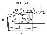
- FIG. 1 (a), 1 (b), and 1 (c) are cross-sectional views showing a nose portion of a threaded joint for pipes according to an embodiment of the present invention.
- FIG. 1 (a) shows a pin member 3; ) Shows the box member 1, and (c) shows a state in which the pin member 3 and the box member 1 are coupled.
- the pin member 3 is provided at an end portion of the steel pipe, and includes a male screw portion 7, a nose portion 8 connected to the pipe end side from the male screw portion 7, and a torque shoulder portion 12 provided at the tip of the nose portion 8.
- the box member 1 includes a female screw portion 5 that is screw-coupled with the male screw portion 7 of the pin member 3, and an outer peripheral surface (nose portion) of the nose portion 8 in a coupled state of the pin member 3 and the box member 1 by the screw coupling. It has a tapered surface 20 that is an inner peripheral surface of the box member 1 that faces the outer peripheral surface 30) and a shoulder portion 14 that abuts against the shoulder portion 12.
- the outer peripheral surface 30 of the nose portion has an outwardly convex curve in the axial sectional view of the pin member 3.
- the inner peripheral surface of the box member 1 facing the outer peripheral surface 30 of the nose portion is a tapered surface 20 (conical surface) having a constant inclination angle (referred to as a taper angle) ⁇ with respect to the axial direction of the threaded joint.
- the taper angle ⁇ is defined by the convex curve and the generatrix of the taper surface 20 in a sectional view in the axial direction of a threaded joint in a virtual non-interference connection state between the pin member 3 and the box member 1 (imaginary make up stage without interference). Are actually set to intersect at two points, and the seal portion 40 is actually formed within a range (interference area 40a) sandwiched between the two intersections.
- the convex curve formed on the outer peripheral surface 30 of the nose portion will be described using the case of a composite R curve with three arcs shown in FIG.
- This curve, composite obtained by sequentially connecting the circular arc N 1, N 2, N 3 having a curvature radius R 1, R 2, R 3 of different line segment N 0 is a generating line of the cylindrical portion adjacent to the male screw portion 7
- the R curve N has a curved shape in which the radius of curvature of the arc increases as the distance from the male thread 7 increases, that is, R 1 ⁇ R 2 ⁇ R 3 .
- the thickness (shoulder thickness) t of the shoulder portion 12 at the tip of the pin nose 8 can be increased.
- the composite R curve N has a curved shape in which the tangent line at the connection point of the arc coincides with that of the connection partner arc. For example, at the connection point between the arcs N 1 and N 2 and at the connection point between the arcs N 2 and N 3 , the tangents of both connected arcs are made to coincide. Therefore, the convex curve has a continuous curve shape with no inflection point on the curve, and unauthorized deformation of the nose portion is suppressed.
- the arcs to be connected may be directly connected to each other, or a line segment that overlaps a common tangent line between the arcs, or an arc having a sufficiently large radius that does not require substantial change in angle (the radius is It may be connected via 250 mm or more and 3 times or more of the adjacent arc.
- the length of the arc having a sufficiently large line segment or radius is preferably 2.5 mm or less.
- angles ⁇ 1 , ⁇ 2 , and ⁇ 3 formed by the arcs N 1 , N 2 , and N 3 are larger as the arc is closer to the male screw portion 7, that is, ⁇ 1 > ⁇ 2 > ⁇ 3. It is preferable that Otherwise, the length of the nose portion 8 of the limited pin member 3 (the pin nose length L in FIG. 1 (a)) or the length of the limited interference zone 40a (the seal contact length). It becomes difficult to design a composite R curve.
- connection point of the circular arc in the composite R curve for example, the connection point of the circular arcs N 1 and N 2 or the connection point of the circular arcs N 2 and N 3 is one of the tapered surface 20 of the box member 1. It is preferable to coincide with a contact start point that means a point to be contacted first.
- the contact surface pressure distribution of the seal portion includes a portion where R is large, the surface pressure is low, and the contact length is long, and R is small. A portion having a high contact pressure and a short contact length can be formed, and a leak path is hardly formed, and the sealing performance is improved.
- the inclination of the tangent line at the connection point of the arc is preferably made smaller than the inclination of the tapered surface of the box member in a range up to 0.5 degrees.
- deformation that causes the tip of the pin to taper due to radial interference between the pin and the box occurs, and the tangential slope of the pin surface at the time of tightening is greater than the design value. .
- the contact start point is preferably set to a distance x from the front end of the male screw portion (see FIG. 1C) of 0.7 L from the viewpoint of separating the seal portion from the front end of the nose.
- L is a pin nose length, and when the distance from the tip of the male screw portion at the contact start point is less than 0.2 L, interference between the seal portion and the screw portion is likely to occur during tightening, so 0.2 L or more. Is good. Furthermore, 0.3L or more is good for safety.
- the taper angle ⁇ (see FIG. 1B) of the tapered surface 20 of the box member 1 is preferably within 10 degrees. By making the taper angle ⁇ within 10 degrees, more preferably within 5 degrees, the radial seal method can be suitably realized, and the tightening torque dependency of the seal performance becomes relatively low.
- the pin nose length L (see FIG. 1A) is preferably 20 mm or more. According to this, the seal part is sufficiently separated from the tip of the pin nose, and as a result, damage (damage) to the seal part can be greatly reduced by elastic deformation within this separation distance range, which is effective in stabilizing the seal performance. Is. Since the seal performance is stabilized, the seal interference amount S (see FIG. 1C) can be relatively small as a radial seal method, and the galling risk is small.
- two or more types of R in the composite R curve are preferably 1 inch or less for a relatively small R, 2 inches or more for a relatively large R, and more preferably 3 inches or more.
- at least one of a plurality of Rs in the composite R curve is 2 inches or more (more preferably 3 inches or more), and at least one R is less than 2 inches (more preferably 1 inch or less). Is preferred.
- the number of arcs in the composite R curve may be two, may be three illustrated in FIG. 1A, or may be four or more.
- the seal contact length becomes larger and it is easier to improve the sealing performance.
- the load and dimension confirmation in actual manufacturing may increase, so the number of arcs is actually a threaded joint. It is better to design according to the performance required for the system.
- the cross-sectional area of the pin member at the contact start point is 35% or more of the cross-sectional area of the main body of the pipe that forms the joint at the tip (cross-sectional area of the unprocessed pin portion).
- the rigidity in the contact start point of a pin member increases, and it becomes easy to obtain especially high external pressure-proof performance.
- the cross-sectional area of the pin member at the contact start point is 40% or more of the cross-sectional area of the pipe body.
- any one or two or more of the load flank angle, the stub flank angle, and the screw gap are defined in a preferable range. It was confirmed that the overall sealing performance was further improved by the combined effect.
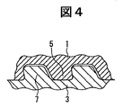
- the load flank angle is the load flank angle ⁇ shown in FIG. 5, that is, the angle ⁇ formed by the load flank surface 18 with respect to the joint axis orthogonal plane (meaning the plane orthogonal to the axial direction of the threaded joint; the same applies hereinafter). It is.
- the stub flank angle is a stub flank angle ⁇ shown in FIG.
- the screw gap is a screw gap G shown in FIG. 5, that is, a gap G between the thread 7a of the male screw and the screw groove 5a of the female screw meshing with the screw thread 7a.
- the preferable range of the load flank angle ⁇ is -5 ° to 4 °.
- the lower limit of the preferable range is determined from the viewpoint of galling resistance and tool life of the threaded portion, and the upper limit is determined from the viewpoint of bending resistance.
- the preferred range of the stub flank angle ⁇ is 0 ° to 30 °.
- the lower limit of the preferred range is from the viewpoint of the galling resistance and tool life of the threaded portion, the tightening property, and the upper limit is from the viewpoint of axial compression resistance. Respectively.
- the preferable range of the screw gap G is 0.01 to 0.1 mm.
- the lower limit of the preferable range is determined from the viewpoint of reducing the goring risk, and the upper limit is determined from the viewpoint of reducing the load on the pin tip during the axial compression load. It was.
- the screw gap G is preferably about 0.03 mm at least. Moreover, since it discovered that the screw gap G was about 0.045 mm and can exhibit sufficient performance effectively, it is good also as about 0.045 mm according to a condition.
- the overall effect of improving the sealing performance is particularly the axial tension + internal pressure or This is remarkable under conditions where external pressure is applied.
- the shoulder angle of the shoulder portion (the angle formed by the end surface of the shoulder portion in the joint axis direction with respect to the joint axis orthogonal surface, and the pin outer peripheral side of the interface protruding from the pin inner peripheral side to the outer side in the joint axial direction)
- the positive angle is preferably 0 to 20 degrees.
- the shoulder angle is less than 0 degree, it is disadvantageous in terms of sealing performance and tightening characteristics, while if it exceeds 20 degrees, it is disadvantageous in that plastic deformation of the box shoulder part and local deformation of the seal part are likely to occur. It becomes. Preferably it is 15 degrees or less. Furthermore, depending on the situation, 7 degrees or less is preferable.
- the contact area pressure is obtained by integrating the contact surface pressure in the seal contact area.
- This leak test is conducted for a threaded joint for pipes, with a biaxial stress and internal pressure corresponding to 95% of the yield condition of the material, and a biaxial stress or material yield condition of 95 corresponding to the Collapse condition described in ISO 10400: 2007.
- the load test based on the smaller biaxial stress of the biaxial stress corresponding to% and the external pressure is carried out, and the load is loaded with the history shown in FIG.
- an index indicating the risk of goling during screw tightening it is defined as the product of sliding distance (inch) and contact surface pressure (psi) at each position in the axial direction of the seal portion from the start to the end of tightening.
- the value of galling index (psi ⁇ inch) contact surface pressure ⁇ sliding distance was determined by FEM analysis. This is also obtained by integration calculation. It can be said that the smaller the Goring index, the smaller the Goring risk.
- Comparative Examples 1, 3, and 4 When the bus bar on the outer peripheral surface of the pin nose 8 is a convex curve having a single R (single R curve M indicated by a broken line in FIG.
- Table 1 shows the contact area pressure and goring index obtained by FEM calculation, and the maximum and minimum seal interference amounts obtained by actual physical tests and repeated tightening tests, together with the dimensions of each part of the threaded joint, for the inventive examples and comparative examples.
- the amount of seal interference in Tables 1 and 2 is a value per diameter, and is a value corresponding to the amount of seal interference S ⁇ 2 shown in FIG.
- the contact area pressure under the internal pressure condition in the FEM calculation is a minimum value (most leak occurs) in the vicinity of the load step (load step) _L3 and L18 (biaxial tensile stress + internal pressure) in the history of FIG. Equivalent to easy state).
- the minimum values of L3 and L18 are expressed as ratios relative to the minimum value of 100 in all examples of L3 and L18.
- the minimum value of L15 is expressed as a ratio with respect to the minimum value of 100 as the minimum value in all examples of L15.
- Tables 1 and 2 display the maximum value of the Goring index of each example as a relative maximum value (representing the maximum maximum value as 100 in all examples, and the other maximum values). did.
- the evaluation results at other sizes are shown in Table 3.
- the target materials have an outer diameter of 139.7 mm, a wall thickness of 7.72 mm, and 5 TPI, and an outer diameter of 346.08 mm, a wall thickness of 15.88 mm, and 4 TPI.
- the inventive examples showed excellent sealing properties after compression history and excellent galling resistance during tightening.
Landscapes
- Engineering & Computer Science (AREA)
- General Engineering & Computer Science (AREA)
- Mechanical Engineering (AREA)
- Mining & Mineral Resources (AREA)
- Life Sciences & Earth Sciences (AREA)
- Geology (AREA)
- Fluid Mechanics (AREA)
- Environmental & Geological Engineering (AREA)
- Physics & Mathematics (AREA)
- General Life Sciences & Earth Sciences (AREA)
- Geochemistry & Mineralogy (AREA)
- Non-Disconnectible Joints And Screw-Threaded Joints (AREA)
- Earth Drilling (AREA)
Abstract
Priority Applications (8)
| Application Number | Priority Date | Filing Date | Title |
|---|---|---|---|
| US13/807,883 US9194190B2 (en) | 2010-06-30 | 2011-06-22 | Threaded joint for pipe |
| MX2012014880A MX336628B (es) | 2010-06-30 | 2011-06-22 | Junta roscada para tubo. |
| RU2013103811/06A RU2522756C1 (ru) | 2010-06-30 | 2011-06-22 | Резьбовое соединение для труб |
| CA2801204A CA2801204C (fr) | 2010-06-30 | 2011-06-22 | Joint filete pour tuyau |
| BR112012033452-2A BR112012033452B1 (pt) | 2010-06-30 | 2011-06-22 | Junta rosqueada para tubo |
| EP17156626.8A EP3196524B1 (fr) | 2010-06-30 | 2011-06-22 | Raccord fileté pour tuyau |
| AU2011272607A AU2011272607B2 (en) | 2010-06-30 | 2011-06-22 | Threaded joint for pipe |
| EP11800871.3A EP2589846B1 (fr) | 2010-06-30 | 2011-06-22 | Couplage vissé de tuyau |
Applications Claiming Priority (6)
| Application Number | Priority Date | Filing Date | Title |
|---|---|---|---|
| JP2010149547 | 2010-06-30 | ||
| JP2010-149547 | 2010-06-30 | ||
| JP2010-289785 | 2010-12-27 | ||
| JP2010289785 | 2010-12-27 | ||
| JP2011-101329 | 2011-04-28 | ||
| JP2011101329A JP4930647B1 (ja) | 2010-06-30 | 2011-04-28 | 管用ねじ継手 |
Publications (1)
| Publication Number | Publication Date |
|---|---|
| WO2012002409A1 true WO2012002409A1 (fr) | 2012-01-05 |
Family
ID=45402114
Family Applications (1)
| Application Number | Title | Priority Date | Filing Date |
|---|---|---|---|
| PCT/JP2011/064862 WO2012002409A1 (fr) | 2010-06-30 | 2011-06-22 | Couplage vissé de tuyau |
Country Status (13)
| Country | Link |
|---|---|
| US (1) | US9194190B2 (fr) |
| EP (2) | EP3196524B1 (fr) |
| JP (1) | JP4930647B1 (fr) |
| CN (2) | CN202469289U (fr) |
| AR (1) | AR081782A1 (fr) |
| AU (1) | AU2011272607B2 (fr) |
| BR (1) | BR112012033452B1 (fr) |
| CA (1) | CA2801204C (fr) |
| MX (1) | MX336628B (fr) |
| MY (1) | MY156120A (fr) |
| RU (1) | RU2522756C1 (fr) |
| SA (1) | SA111320568B1 (fr) |
| WO (1) | WO2012002409A1 (fr) |
Cited By (4)
| Publication number | Priority date | Publication date | Assignee | Title |
|---|---|---|---|---|
| JP2014001820A (ja) * | 2012-06-20 | 2014-01-09 | Jfe Steel Corp | 鋼管用ねじ継手 |
| WO2014115191A1 (fr) * | 2013-01-28 | 2014-07-31 | Jfeスチール株式会社 | Accouplement à vis pour tuyau en acier |
| WO2014092605A3 (fr) * | 2012-12-13 | 2014-08-07 | Tmk-Premium Services Llc | Raccord fileté hermétiquement scellé pour tuyaux d'enveloppe (versions) |
| WO2017141538A1 (fr) * | 2016-02-19 | 2017-08-24 | Jfeスチール株式会社 | Joint fileté pour conduite de puits de pétrole |
Families Citing this family (23)
| Publication number | Priority date | Publication date | Assignee | Title |
|---|---|---|---|---|
| JP4930647B1 (ja) * | 2010-06-30 | 2012-05-16 | Jfeスチール株式会社 | 管用ねじ継手 |
| WO2012112570A1 (fr) | 2011-02-14 | 2012-08-23 | The Regents Of The University Of California | Dérivés de sorafénib utilisés en tant qu'inhibiteurs de la seh |
| JP5849749B2 (ja) * | 2011-02-28 | 2016-02-03 | Jfeスチール株式会社 | 管用ねじ継手 |
| JP5923911B2 (ja) * | 2011-03-22 | 2016-05-25 | Jfeスチール株式会社 | 鋼管用ねじ継手 |
| JP5891700B2 (ja) * | 2011-10-17 | 2016-03-23 | Jfeスチール株式会社 | 管のねじ継手 |
| RU2500875C1 (ru) * | 2012-07-20 | 2013-12-10 | Общество С Ограниченной Ответственностью "Тмк-Премиум Сервис" | Высокогерметичное резьбовое соединение насосно-компрессорных труб (варианты) |
| JP6020087B2 (ja) * | 2012-11-22 | 2016-11-02 | Jfeスチール株式会社 | 管用ねじ継手 |
| JP5803953B2 (ja) | 2013-02-18 | 2015-11-04 | Jfeスチール株式会社 | 管接続用ねじ継手 |
| CA2921411C (fr) | 2013-09-06 | 2018-07-10 | Nippon Steel & Sumitomo Metal Corporation | Raccord filete pour tuyau en acier |
| MX2017009201A (es) * | 2015-01-15 | 2018-04-24 | Jfe Steel Corp | Junta atornillada para tubo. |
| US10041307B2 (en) | 2015-01-22 | 2018-08-07 | National Oilwell Varco, L.P. | Balanced thread form, tubulars employing the same, and methods relating thereto |
| UA122027C2 (uk) * | 2016-08-24 | 2020-08-25 | ДжФЕ СТІЛ КОРПОРЕЙШН | Різьбове з'єднання для трубних виробів нафтопромислового сортаменту |
| FR3060701A1 (fr) * | 2016-12-16 | 2018-06-22 | Vallourec Oil And Gas France | Joint filete pour composant tubulaire |
| BR112019020896B1 (pt) * | 2017-05-22 | 2023-01-24 | Nippon Steel Corporation | Conexão roscada para tubos de aço |
| UA123131C2 (uk) * | 2017-11-09 | 2021-02-17 | Ніппон Стіл Корпорейшн | Нарізне з'єднання для сталевої труби |
| JP7012858B2 (ja) * | 2018-08-21 | 2022-01-28 | 日本製鉄株式会社 | 鋼管用ねじ継手 |
| CN109915667B (zh) * | 2019-04-15 | 2020-02-07 | 大连长之琳科技发展有限公司 | 一种内旋滚压式密封接头、轻型直通管接头及其应用 |
| CN110608322B (zh) * | 2019-09-11 | 2024-04-12 | 江苏璞腾油气装备有限公司 | 一种四线海洋隔水管接头 |
| AU2020423748B2 (en) | 2020-01-17 | 2023-09-07 | Nippon Steel Corporation | Threaded connection for pipe |
| AU2020422897B2 (en) * | 2020-01-17 | 2023-11-02 | Nippon Steel Corporation | Threaded connection for pipe |
| CN114761722B (zh) | 2020-01-17 | 2024-01-02 | 日本制铁株式会社 | 管用螺纹接头 |
| DE202020107520U1 (de) * | 2020-12-23 | 2021-02-01 | L.L.C. "Interpipe Management" | Dichte Metallrohrgewindeverbindung |
| FR3121492B1 (fr) * | 2021-03-31 | 2023-02-24 | Vallourec Oil & Gas France | Dimensionnement d’un jeu axial de filetage |
Citations (9)
| Publication number | Priority date | Publication date | Assignee | Title |
|---|---|---|---|---|
| JPS6144068A (ja) | 1984-08-07 | 1986-03-03 | 三菱電機株式会社 | 鉄道車両の蛇行動防止装置 |
| JPS6144068Y2 (fr) * | 1982-04-16 | 1986-12-12 | ||
| JP2705506B2 (ja) | 1993-03-24 | 1998-01-28 | 住友金属工業株式会社 | 油井管用ねじ継手 |
| JP2001124253A (ja) | 1999-10-29 | 2001-05-11 | Kawasaki Steel Corp | 鋼管用ネジ継手 |
| JP2002522713A (ja) * | 1998-07-31 | 2002-07-23 | マンネスマン・アクチエンゲゼルシャフト | 管継手 |
| JP4208192B2 (ja) | 2001-12-07 | 2009-01-14 | バローレック・マネスマン・オイル・アンド・ガス・フランス | 端部リップを備える少なくとも1つのねじ部分を含む高品質なねじ付き管継手 |
| WO2009083523A1 (fr) * | 2007-12-28 | 2009-07-09 | Vallourec Mannesmann Oil & Gas France | Raccord tubulaire fileté scellé résistant à des charges de pression successives |
| JP4300187B2 (ja) | 2002-09-06 | 2009-07-22 | テナリス・コネクシヨンズ・アクチエンゲゼルシヤフト | ねじ管継手 |
| JP4535064B2 (ja) | 2003-06-06 | 2010-09-01 | 住友金属工業株式会社 | 鋼管用ねじ継手 |
Family Cites Families (14)
| Publication number | Priority date | Publication date | Assignee | Title |
|---|---|---|---|---|
| DE1533619B2 (fr) * | 1967-04-28 | 1970-06-11 | ||
| US4588213A (en) * | 1983-10-05 | 1986-05-13 | Thread Technology International, Inc. | Threaded pipe connection |
| JPS6144068U (ja) | 1984-08-27 | 1986-03-24 | 株式会社 コスモ計器 | 絞り装置 |
| US5137310A (en) * | 1990-11-27 | 1992-08-11 | Vallourec Industries | Assembly arrangement using frustoconical screwthreads for tubes |
| FR2725773B1 (fr) * | 1994-10-13 | 1996-11-29 | Vallourec Oil & Gas | Assemblage filete pour tubes |
| FR2733570B1 (fr) * | 1995-04-28 | 1997-06-20 | Vallourec Oil & Gas | Assemblage filete pour tubes |
| FR2761450B1 (fr) * | 1997-03-27 | 1999-05-07 | Vallourec Mannesmann Oil & Gas | Joint filete pour tubes |
| MXPA02012145A (es) * | 2000-06-09 | 2004-08-19 | Sumitomo Metal Ind | Junta de tuberia. |
| FR2863681B1 (fr) * | 2003-12-11 | 2006-02-24 | Vallourec Mannesmann Oil & Gas | Joint tubulaire a filetages coniques resistant a la fatigue |
| JP2007205361A (ja) * | 2004-08-27 | 2007-08-16 | Sumitomo Metal Ind Ltd | 鋼管用ねじ継手 |
| FR2913746B1 (fr) * | 2007-03-14 | 2011-06-24 | Vallourec Mannesmann Oil & Gas | Joint filete tubulaire etanche pour sollicitations de pression interieure et exterieure |
| JP5250990B2 (ja) * | 2007-03-28 | 2013-07-31 | 新日鐵住金株式会社 | 油井管用ねじ継手 |
| BRPI0920855B1 (pt) * | 2008-10-20 | 2020-09-15 | Nippon Steel Corporation | Junta rosqueada para tubos de aço |
| JP4930647B1 (ja) * | 2010-06-30 | 2012-05-16 | Jfeスチール株式会社 | 管用ねじ継手 |
-
2011
- 2011-04-28 JP JP2011101329A patent/JP4930647B1/ja active Active
- 2011-06-22 US US13/807,883 patent/US9194190B2/en active Active
- 2011-06-22 CA CA2801204A patent/CA2801204C/fr active Active
- 2011-06-22 BR BR112012033452-2A patent/BR112012033452B1/pt active IP Right Grant
- 2011-06-22 RU RU2013103811/06A patent/RU2522756C1/ru active
- 2011-06-22 MY MYPI2012005551A patent/MY156120A/en unknown
- 2011-06-22 EP EP17156626.8A patent/EP3196524B1/fr active Active
- 2011-06-22 WO PCT/JP2011/064862 patent/WO2012002409A1/fr active Application Filing
- 2011-06-22 AU AU2011272607A patent/AU2011272607B2/en active Active
- 2011-06-22 EP EP11800871.3A patent/EP2589846B1/fr active Active
- 2011-06-22 MX MX2012014880A patent/MX336628B/es unknown
- 2011-06-29 SA SA111320568A patent/SA111320568B1/ar unknown
- 2011-06-29 AR ARP110102284A patent/AR081782A1/es active IP Right Grant
- 2011-06-30 CN CN2011202356277U patent/CN202469289U/zh not_active Expired - Fee Related
- 2011-06-30 CN CN201110189469.0A patent/CN102313085B/zh active Active
Patent Citations (9)
| Publication number | Priority date | Publication date | Assignee | Title |
|---|---|---|---|---|
| JPS6144068Y2 (fr) * | 1982-04-16 | 1986-12-12 | ||
| JPS6144068A (ja) | 1984-08-07 | 1986-03-03 | 三菱電機株式会社 | 鉄道車両の蛇行動防止装置 |
| JP2705506B2 (ja) | 1993-03-24 | 1998-01-28 | 住友金属工業株式会社 | 油井管用ねじ継手 |
| JP2002522713A (ja) * | 1998-07-31 | 2002-07-23 | マンネスマン・アクチエンゲゼルシャフト | 管継手 |
| JP2001124253A (ja) | 1999-10-29 | 2001-05-11 | Kawasaki Steel Corp | 鋼管用ネジ継手 |
| JP4208192B2 (ja) | 2001-12-07 | 2009-01-14 | バローレック・マネスマン・オイル・アンド・ガス・フランス | 端部リップを備える少なくとも1つのねじ部分を含む高品質なねじ付き管継手 |
| JP4300187B2 (ja) | 2002-09-06 | 2009-07-22 | テナリス・コネクシヨンズ・アクチエンゲゼルシヤフト | ねじ管継手 |
| JP4535064B2 (ja) | 2003-06-06 | 2010-09-01 | 住友金属工業株式会社 | 鋼管用ねじ継手 |
| WO2009083523A1 (fr) * | 2007-12-28 | 2009-07-09 | Vallourec Mannesmann Oil & Gas France | Raccord tubulaire fileté scellé résistant à des charges de pression successives |
Non-Patent Citations (1)
| Title |
|---|
| See also references of EP2589846A4 |
Cited By (11)
| Publication number | Priority date | Publication date | Assignee | Title |
|---|---|---|---|---|
| JP2014001820A (ja) * | 2012-06-20 | 2014-01-09 | Jfe Steel Corp | 鋼管用ねじ継手 |
| WO2014092605A3 (fr) * | 2012-12-13 | 2014-08-07 | Tmk-Premium Services Llc | Raccord fileté hermétiquement scellé pour tuyaux d'enveloppe (versions) |
| EA031821B1 (ru) * | 2012-12-13 | 2019-02-28 | Общество С Ограниченной Ответственностью "Тмк-Премиум Сервис" | Высокогерметичное резьбовое соединение обсадных труб |
| WO2014115191A1 (fr) * | 2013-01-28 | 2014-07-31 | Jfeスチール株式会社 | Accouplement à vis pour tuyau en acier |
| JP5949953B2 (ja) * | 2013-01-28 | 2016-07-13 | Jfeスチール株式会社 | 鋼管用ねじ継手 |
| US10202809B2 (en) | 2013-01-28 | 2019-02-12 | Jfe Steel Corporation | Threaded joint for steel pipes |
| WO2017141538A1 (fr) * | 2016-02-19 | 2017-08-24 | Jfeスチール株式会社 | Joint fileté pour conduite de puits de pétrole |
| JP6187724B1 (ja) * | 2016-02-19 | 2017-08-30 | Jfeスチール株式会社 | 油井管用ねじ継手 |
| AU2016393093B2 (en) * | 2016-02-19 | 2019-05-02 | Jfe Steel Corporation | Threaded joint for oil well tubing |
| RU2692177C1 (ru) * | 2016-02-19 | 2019-06-21 | ДжФЕ СТИЛ КОРПОРЕЙШН | Резьбовое соединение насосно-компрессорных труб для нефтяных скважин |
| US10900595B2 (en) | 2016-02-19 | 2021-01-26 | Jfe Steel Corporation | Threaded joint for oil well tubing |
Also Published As
| Publication number | Publication date |
|---|---|
| US9194190B2 (en) | 2015-11-24 |
| SA111320568B1 (ar) | 2014-05-21 |
| RU2522756C1 (ru) | 2014-07-20 |
| BR112012033452B1 (pt) | 2020-09-29 |
| AU2011272607B2 (en) | 2015-03-12 |
| EP3196524B1 (fr) | 2021-06-09 |
| CN202469289U (zh) | 2012-10-03 |
| JP4930647B1 (ja) | 2012-05-16 |
| US20130181442A1 (en) | 2013-07-18 |
| AR081782A1 (es) | 2012-10-17 |
| JP2012149760A (ja) | 2012-08-09 |
| BR112012033452A2 (pt) | 2016-12-13 |
| EP3196524A1 (fr) | 2017-07-26 |
| CN102313085A (zh) | 2012-01-11 |
| MX336628B (es) | 2016-01-26 |
| MX2012014880A (es) | 2013-01-24 |
| MY156120A (en) | 2016-01-15 |
| AU2011272607A1 (en) | 2012-12-20 |
| CN102313085B (zh) | 2015-10-14 |
| EP2589846B1 (fr) | 2017-06-14 |
| CA2801204A1 (fr) | 2012-01-05 |
| CA2801204C (fr) | 2016-08-09 |
| EP2589846A1 (fr) | 2013-05-08 |
| EP2589846A4 (fr) | 2015-04-01 |
Similar Documents
| Publication | Publication Date | Title |
|---|---|---|
| WO2012002409A1 (fr) | Couplage vissé de tuyau | |
| JP5660308B2 (ja) | 鋼管用ねじ継手 | |
| JP5849749B2 (ja) | 管用ねじ継手 | |
| CN107101054B (zh) | 油井管用螺纹接头 | |
| JP7120179B2 (ja) | 油井管用ねじ継手 | |
| WO2012128015A1 (fr) | Joint à vis pour canalisation en acier | |
| JP6103137B2 (ja) | 管用ねじ継手 | |
| WO2020075342A1 (fr) | Assemblage fileté | |
| JP5673089B2 (ja) | 鋼管用ねじ継手 | |
| JP6020087B2 (ja) | 管用ねじ継手 | |
| JP5906588B2 (ja) | 鋼管用ねじ継手の製造方法 | |
| JP5776222B2 (ja) | 鋼管用ねじ継手 | |
| JP5673090B2 (ja) | 鋼管用ねじ継手 | |
| JP6051811B2 (ja) | 管用ねじ継手 | |
| WO2014125545A1 (fr) | Joint fileté pour un tuyau | |
| JP5906587B2 (ja) | 鋼管用ねじ継手の製造方法 |
Legal Events
| Date | Code | Title | Description |
|---|---|---|---|
| 121 | Ep: the epo has been informed by wipo that ep was designated in this application |
Ref document number: 11800871 Country of ref document: EP Kind code of ref document: A1 |
|
| WWE | Wipo information: entry into national phase |
Ref document number: 3667/KOLNP/2012 Country of ref document: IN |
|
| ENP | Entry into the national phase |
Ref document number: 2801204 Country of ref document: CA |
|
| WWE | Wipo information: entry into national phase |
Ref document number: MX/A/2012/014880 Country of ref document: MX |
|
| ENP | Entry into the national phase |
Ref document number: 2011272607 Country of ref document: AU Date of ref document: 20110622 Kind code of ref document: A |
|
| NENP | Non-entry into the national phase |
Ref country code: DE |
|
| ENP | Entry into the national phase |
Ref document number: 2013103811 Country of ref document: RU Kind code of ref document: A |
|
| REEP | Request for entry into the european phase |
Ref document number: 2011800871 Country of ref document: EP |
|
| WWE | Wipo information: entry into national phase |
Ref document number: 2011800871 Country of ref document: EP |
|
| WWE | Wipo information: entry into national phase |
Ref document number: 13807883 Country of ref document: US |
|
| REG | Reference to national code |
Ref country code: BR Ref legal event code: B01A Ref document number: 112012033452 Country of ref document: BR |
|
| ENP | Entry into the national phase |
Ref document number: 112012033452 Country of ref document: BR Kind code of ref document: A2 Effective date: 20121227 |