WO2012118071A1 - 流体制御弁 - Google Patents
流体制御弁 Download PDFInfo
- Publication number
- WO2012118071A1 WO2012118071A1 PCT/JP2012/054918 JP2012054918W WO2012118071A1 WO 2012118071 A1 WO2012118071 A1 WO 2012118071A1 JP 2012054918 W JP2012054918 W JP 2012054918W WO 2012118071 A1 WO2012118071 A1 WO 2012118071A1
- Authority
- WO
- WIPO (PCT)
- Prior art keywords
- valve
- load
- pressure
- valve body
- flexible member
- Prior art date
- Legal status (The legal status is an assumption and is not a legal conclusion. Google has not performed a legal analysis and makes no representation as to the accuracy of the status listed.)
- Ceased
Links
Images




Classifications
-
- F—MECHANICAL ENGINEERING; LIGHTING; HEATING; WEAPONS; BLASTING
- F16—ENGINEERING ELEMENTS AND UNITS; GENERAL MEASURES FOR PRODUCING AND MAINTAINING EFFECTIVE FUNCTIONING OF MACHINES OR INSTALLATIONS; THERMAL INSULATION IN GENERAL
- F16K—VALVES; TAPS; COCKS; ACTUATING-FLOATS; DEVICES FOR VENTING OR AERATING
- F16K31/00—Actuating devices; Operating means; Releasing devices
- F16K31/12—Actuating devices; Operating means; Releasing devices actuated by fluid
- F16K31/122—Actuating devices; Operating means; Releasing devices actuated by fluid the fluid acting on a piston
- F16K31/1221—Actuating devices; Operating means; Releasing devices actuated by fluid the fluid acting on a piston one side of the piston being spring-loaded
-
- F—MECHANICAL ENGINEERING; LIGHTING; HEATING; WEAPONS; BLASTING
- F16—ENGINEERING ELEMENTS AND UNITS; GENERAL MEASURES FOR PRODUCING AND MAINTAINING EFFECTIVE FUNCTIONING OF MACHINES OR INSTALLATIONS; THERMAL INSULATION IN GENERAL
- F16K—VALVES; TAPS; COCKS; ACTUATING-FLOATS; DEVICES FOR VENTING OR AERATING
- F16K41/00—Spindle sealings
- F16K41/10—Spindle sealings with diaphragm, e.g. shaped as bellows or tube
- F16K41/103—Spindle sealings with diaphragm, e.g. shaped as bellows or tube the diaphragm and the closure member being integrated in one member
Definitions
- the present invention relates to a general purpose fluid control valve, and more particularly to a fluid control valve used for controlling chemicals and pure water used for manufacturing parts of products such as semiconductors, flat panel displays and solar cells.
- single-acting and double-acting diaphragm valves may be used to control the flow rate of chemicals used in semiconductor manufacturing.
- the diaphragm valve body is urged in the valve closing direction, while a driving force is applied in the valve opening direction, and the valve opening is operated by a balance between the urging force and the driving force.
- the valve opening degree is operated by a balance between driving forces in the valve opening direction and the valve closing direction.
- the present inventors have proposed a method for reducing the biasing force and suppressing the water hammer phenomenon by changing the shape of the diaphragm valve (Patent Document 1). Specifically, the position of the base of the membrane portion of the diaphragm valve body is set inside the diameter of the valve seat, and the outer dimension of the diaphragm valve body is reduced. The outer dimensions of the diaphragm valve body receive the pressure of the chemical solution and counteract the urging force, and also serve as a pressure-receiving surface for the water hammer phenomenon, so that the problem is solved by reducing it. That is, the present inventors have found a method of suppressing the problem of the diaphragm valve body that receives a driving force by the pressure of the chemical liquid by reducing the pressure receiving area of the chemical liquid.
- the present inventor is not satisfied with the above-mentioned result, and further eliminates the problem of the diaphragm valve body that receives the driving force by the pressure of the chemical solution by reducing not only the pressure receiving area but also in principle. It worked on the development of.
- the present invention was created to solve the above-described conventional problems, and aims to provide a technique for improving the operability of a control valve that controls the flow of fluid.
- a valve main body provided with a main body side valve seat surface surrounding the communication port of the first flow path and the second flow path, the first flow path and the second flow path communicating with each other;
- the valve body side valve seat surface is seated on the main body side valve seat surface, and the valve body side valve seat surface is seated on the main body side valve seat surface and the valve body side valve seat surface is separated from the main body side valve seat surface.
- a valve body portion that is displaced so as to be in a state, the valve body portion having flexibility, and a first flexible member that seals the first flow path from the outside of the valve body;
- a second flexible member having flexibility and sealing the second flow path from the outside of the valve body; and connected to the first flexible member and the second flexible member.
- Comprising The 1 flexible member has a valve opening direction load that is a load in a valve opening direction that separates the valve body side valve seat surface from the main body side valve seat surface in accordance with a first pressure in the first flow path.
- the second flexible member is closed by a valve closing load that causes the valve-side valve seat surface to seat on the main-body-side valve seat surface in accordance with the second pressure in the second flow path.
- a valve direction load is applied to the valve body portion, and the valve seat portion applies a first reduced load that is a load in a direction to reduce the valve opening direction load according to the first pressure during the seating.
- a fluid control valve characterized by applying a second reduced load, which is a load in a direction to reduce the valve closing direction load in accordance with the second pressure, to the valve body portion.
- Means 1 includes a valve seat portion that generates a first reduced load that is a load in a direction that reduces the load in the valve opening direction and a second reduced load that is a load in the direction that reduces the load in the valve closing direction.
- first pressure or second pressure the load applied to the valve body can be canceled in principle by the pressure in the flow path (first pressure or second pressure), so the required specification of this load can be set in the setting of the driving force specification.
- the present inventor succeeded in halving the driving pressure and the consumption of the working air by driving the valve body part with the working air in a single-acting fluid control valve. This means can also be applied to a dynamic type.
- the occurrence of the water hammer phenomenon can be effectively suppressed.
- the occurrence of the water hammer phenomenon is caused by the valve body portion being accelerated due to the load applied to the valve body portion by the fluid pressure, and the flow path being suddenly shut off.
- the means 1 since the load applied to the valve body portion by the pressure of the fluid is reduced by cancellation, acceleration of the valve body portion can be effectively suppressed.
- valve opening direction load and the valve closing direction load mean loads applied to the valve body portion among loads generated by the fluid pressure by the first flexible member and the second flexible member, respectively. Therefore, it does not mean all the loads generated by the first flexible member or the second flexible member, but has a meaning as a shared load that the valve body side takes on among the loads.
- the shared load defines the area of the pressure receiving surface corresponding to the load (applied load) flowing on the valve body side of the pressure receiving surfaces of the first flexible member and the second flexible member as an effective pressure receiving area, You may make it design a valve seat part on the basis of the area.
- this means is not only a so-called normally closed type fluid control valve, that is, a fluid control valve that is closed when no driving force is applied, but also a so-called normally open type fluid control valve, that is, a drive.
- the present invention can also be applied to a fluid control valve that is in a valve open state when no force is applied.
- the first reduced load is set within a range of 0.8 to 1.2 times the valve opening direction load, and the second reduced load is 0.8 to 1.2 times the valve closing direction load.
- the valve body can be operated. As a result, smooth shut-off operation and precise operation of the valve opening (valve lift amount) can be made possible.
- Means 3 The fluid control valve according to means 1 or 2, wherein the valve-opening direction load is set within a range of 0.8 to 1.2 times the valve-closing direction load when the valve body portion is opened.
- the load applied to the valve body portion is canceled even in the valve open state where the first reduced load and the second reduced load are not generated.
- the transition between the valve closed state and the valve open state (valve open operation and valve close operation) can be further smoothed, so that a smooth shut-off operation and precise operation of the valve opening (valve lift amount) are possible.
- the numerical value is a value determined by the inventor's analysis, simulation (simulation experiment), or the like.
- Means 4 In a state before the first pressure and the second pressure are applied, an initial load is generated on the valve body, and a pressure receiving area of the first flexible member is set to be equal to that of the second flexible member. By setting either the pressure receiving area less than 0.7 times or 1.3 times or more, the valve opening direction load is within the range of 0.8 to 1.2 times the valve closing direction load.
- the valve opening direction load is set by setting the pressure receiving area of the first flexible member to less than 0.7 times or 1.3 times or more of the pressure receiving area of the second flexible member.
- the load was in the range of 0.8 to 1.2 times the valve closing load at the time of sitting. Therefore, for example, even in a configuration in which an initial load is generated in advance before the first pressure or the second pressure is applied, the initial load can be reduced to achieve a load balance at the time of sitting.
- Means 5 The device according to claim 1, further comprising: an urging portion that urges the valve body portion in the valve closing direction; and a driving portion that applies a driving force in the valve opening direction to the valve body portion. Fluid control valve.
- the means 5 can suppress the sinking of the valve seat due to the urging force between the manufacture and use of the fluid control valve. This is because during the period from manufacture to use of the fluid control valve, the valve seat may sink due to the seating of the valve body due to the biasing force, but the seating load can be reduced by reducing the biasing force. .
- Means 6 The fluid control valve according to any one of means 1 to 5, further comprising an electromagnetic drive unit for driving the valve body part by electromagnetic force.
- Means 7 The fluid control valve according to any one of means 1 to 5, further comprising a manual input mechanism for manually driving the valve body portion.
- the means 7 can suppress the occurrence of unexpected driving force on the valve body due to the fluid flow, it is possible to realize a manual type fluid control valve that does not cause unpleasant reaction in human hands. it can.
- Means 8 Any one of means 1 to 7 having a blocking function for blocking a flow of fluid in the first flow path and the second flow path when the valve body side valve seat surface is seated on the main body side valve seat surface. The fluid control valve described.
- Means 8 is an on-off valve having a blocking function for blocking the flow of fluid.
- the on-off valve is desired to be small and light.
- a large driving force has been required to maintain the valve open state in order to cope with the generation of a load on the valve body due to the pressure of the fluid. With this means, the valve open state can be maintained with a small driving force, and the drive unit and the like can be downsized.
- the valve seat portion includes a first pressure receiving surface facing the first flexible member side and a second pressure receiving surface facing the second flexible member side, and the first reduced load is the first reducing load.
- the pressure receiving surface is set according to the amount of protrusion in the radial direction from the shaft portion, and the second reduction load is set according to the amount of protrusion of the second pressure receiving surface from the shaft portion in the radial direction.
- the fluid control valve according to any one of means 1 to 8.
- the first reduced load and the second reduced load can be set according to the protruding amount of the first pressure receiving surface and the second pressure receiving surface from the shaft portion.
- Means 10 The fluid control valve according to claim 9, wherein the protruding amount of the first pressure receiving surface and the pressure receiving area of the first flexible member are set so that the first reduction load and the valve opening direction load substantially coincide.
- the load on the valve body portion based on the first pressure is canceled so that the first reduced load and the valve opening direction load substantially coincide with each other, so that the influence on the valve body portion due to the first pressure is eliminated. be able to.
- Means 11 The fluid control valve according to claim 9 or 10, wherein the protruding amount of the second pressure receiving surface and the pressure receiving area of the second flexible member are set so that the second mitigation load and the valve closing direction load substantially coincide with each other. .
- the means 11 eliminates the influence of the second pressure on the valve body portion because the load on the valve body portion based on the second pressure is canceled so that the second reduced load and the valve closing direction load are substantially matched. be able to.
- Means 12 The pressure receiving area of the first flexible member and the pressure receiving area of the second flexible member are any one of means 1 to 11 configured such that the valve opening direction load and the valve closing direction load substantially coincide with each other. 2.
- the means 12 can sufficiently suppress the load that the valve body receives from the fluid not only in the valve open state but also in the valve open state by making the valve opening direction load and the valve closing direction load substantially coincide with each other. . Therefore, in the transition operation between the valve closed state and the valve open state, unexpected acceleration / deceleration caused by the fluid of the valve body portion can be suppressed.
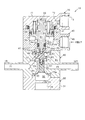
- Sectional drawing which shows the structure of the fluid control valve 10 at the time of valve closing Sectional drawing which shows the structure of the fluid control valve 10 at the time of valve opening.
- the expanded sectional view which shows the structure of the valve body part 50 at the time of valve closing.
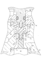
- Sectional drawing which shows the pressure state of the vicinity of the valve body part 50 at the time of valve closing static state.
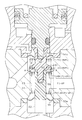
- Sectional drawing which shows the pressure state of the vicinity of the valve body part 50 at the time of valve opening static state.
- FIG. 1 is a cross-sectional view showing the configuration of the fluid control valve 10 when the valve is closed.
- FIG. 2 is a cross-sectional view showing the configuration of the fluid control valve 10 when the valve is open.
- FIG. 3 is an enlarged cross-sectional view showing the configuration of the valve body 50 when the valve is closed.
- the fluid control valve 10 is an open / close valve that turns on and off the flow of a chemical used in a semiconductor manufacturing process. When the fluid control valve 10 is on (valve open state), it is desired that the chemical liquid flows with a small pressure loss, and when the fluid control valve 10 is off (valve closed state), the chemical liquid is surely shut off. Such characteristics are realized by the configuration described below.
- the fluid control valve 10 includes a valve body portion 50, a valve housing 80 that houses the valve body portion 50, a valve cover 30, an actuator 60 that drives the valve body portion 50, an actuator housing 40 that houses the actuator 60, And an actuator cover 70.
- the valve housing 80 is assembled between the actuator housing 40 and the valve cover 30.
- the actuator housing 40 is assembled between the valve housing 80 and the actuator cover 70.
- the valve housing 80 is also called a valve body.
- the valve housing 80 and the valve body 50 can be manufactured as molded parts made of a material having high corrosion resistance to chemicals, for example, a fluorine-based synthetic resin.
- the other components that is, the valve cover 30, the actuator 60, the actuator housing 40, and the actuator cover 70 can be manufactured, for example, as molded parts of polypropylene resin.
- the valve housing 80 and the valve body portion 50 form a chemical flow path as shown in FIGS.
- the chemical liquid flow path is connected to the chemical liquid inlet 21 into which the chemical liquid flows, the upstream valve chamber 23, the connection flow path 22 communicating with the chemical liquid inlet 21 and the upstream valve chamber 23, and the upstream valve chamber 23. It has a downstream valve chamber 24 that communicates, and a chemical solution outlet 25 that communicates with the downstream valve chamber 24 and flows out of the chemical solution.
- the chemical liquid flow path is configured to turn on and off the flow of the chemical liquid by operating (opening and closing) the communication state between the upstream valve chamber 23 and the downstream valve chamber 24 by the valve body portion 50.
- the upstream valve chamber 23 and the downstream valve chamber 24 are also referred to as a first flow path and a second flow path, respectively. Further, in the present embodiment, in order to make the explanation easy to understand, it is assumed that the chemical solution flows in the direction from the upstream valve chamber 23 to the downstream valve chamber 24, but the flow direction of the chemical solution is reversed. May be. That is, the fluid control valve 10 may be used so as to flow from the downstream valve chamber 24 toward the upstream valve chamber 23. Similar effects can be obtained even in such use.
- the chemical solution inlet 21 and the chemical solution outlet 25 are formed in a direction substantially perpendicular to the assembly direction of the valve housing 80, the actuator housing 40, and the valve cover 30, and share the central axis.
- the upstream valve chamber 23 is disposed at a position offset toward the actuator housing 40 from the central axes of the chemical solution inlet 21 and the chemical solution outlet 25.
- the connection flow path 22 extends obliquely from the chemical solution inlet 21 toward the upstream valve chamber 23.
- the upstream valve chamber 23 is stored in an upstream inner hole 83 that forms a cylindrical space formed in the valve housing 80 and a part of the upstream inner hole 83. It is prescribed
- FIG. The upstream side inner hole 83 is connected to a main body side valve seat surface 85 formed as a flat surface forming the bottom surface thereof.
- the upstream inner hole 83 communicates with the downstream inner hole 84 through a communication port 86 surrounded by the main body side valve seat surface 85.
- the downstream inner hole 84 is set to have a sufficiently large diameter so that a sufficient flow path (gap) is formed between the downstream inner hole 84 and the upstream shaft portion 58 described later, and excessive pressure loss does not occur.
- the inner diameter of the downstream inner hole 84 is set so as to have a cross-sectional area equal to or larger than the cross-sectional areas of the chemical liquid inlet 21 and the chemical liquid outlet 25.
- the valve body 50 has a cylindrical upstream shaft (shaft) 58 and a flexible donut-shaped (film-like) connected to the upstream shaft 58 within the upstream inner hole 83.
- the diaphragm 54, the donut-shaped diaphragm support portion 54 a connected over the outer periphery of the diaphragm 54, and the outer peripheral surface of the upstream shaft portion 58 extend in a direction inclined toward the main body side valve seat surface 85 in the radial direction.
- An upstream pressure receiving surface (first pressure receiving surface) 51, a downstream pressure receiving surface (second pressure receiving surface) 52 extending perpendicularly from the outer peripheral surface of the upstream shaft 58 in the radial direction, and a downstream pressure receiving surface 52.
- annular protrusion 53 which is an annular protrusion formed on the surface.
- the annular protrusion 53 protrudes from the downstream pressure receiving surface 52 in the central axis direction of the upstream shaft portion 58.
- the central axis of the upstream shaft part 58 is also called a drive axis.
- the upstream pressure receiving surface 51, the downstream pressure receiving surface 52, and the annular protrusion 53 are also referred to as valve seats.
- the diaphragm 54 is also called a first flexible member.
- the annular protrusion 53 is also called a valve body side valve seat surface. Further, the annular protrusion 53 may be provided on the main body side valve seat surface 85 side. In this case, the surface (the surface of the downstream pressure receiving surface 52) with which the annular protrusion 53 provided on the main body side valve seat surface 85 abuts on the downstream pressure receiving surface 52 is called the valve body side valve seat surface. Become.
- the upstream valve chamber 23 is sealed from the actuator housing 40 side (outside of the valve housing 80) assembled to the valve housing 80 by the diaphragm 54, the diaphragm support portion 54 a, and the upstream shaft portion 58. .
- the diaphragm support portion 54a is sandwiched between the main body member 81 of the valve housing 80 and the main body member 41 of the actuator housing 40, and functions as a sealing member (gasket).
- An upstream shaft portion 58 is connected to the diaphragm support portion 54 a via the diaphragm 54.
- the diaphragm 54 is connected to the diaphragm support portion 54a so that the upstream shaft portion 58 can move in the axial direction thereof, and restricts the radial position of the upstream shaft portion 58.
- the diaphragm 54 defines a retreat space 49 for the diaphragm 54 to move between the main body member 41 of the actuator housing 40.
- the retreat space 49 is open to the atmosphere via a port 48 and an outside air flow path 47. Thereby, the diaphragm 54 can be smoothly changed (displaced / deformed) by changing the internal volume of the retreat space 49.
- the downstream valve chamber 24 is partly stored in a downstream inner hole 84 that forms a cylindrical space formed in the valve housing 80 and a downstream inner hole 84. It is prescribed
- FIG. The valve body 50 has a downstream shaft 56 that is screwed into the upstream shaft 58 with a screw 57 in the downstream inner hole 84, and a flexible member that is connected to the downstream shaft 56.
- a doughnut-shaped (film-like) diaphragm 55 and a donut-shaped diaphragm support portion 55 a connected over the outer periphery of the diaphragm 55 are provided.
- the downstream valve chamber 24 is sealed from the valve cover 30 side (the outside of the valve housing 80) assembled to the valve housing 80 by the diaphragm 55, the diaphragm support portion 55 a, and the downstream shaft portion 56. .
- the diaphragm support portion 55a is sandwiched between the main body member 81 of the valve housing 80 and the main body member 31 of the valve cover 30, and functions as a sealing member (gasket).
- a downstream shaft portion (shaft portion) 56 is connected to the diaphragm support portion 55 a via the diaphragm 55.
- the diaphragm 55 connects the downstream shaft portion 56 to the diaphragm support portion 55a so as to be movable in the axial direction, and constrains the position of the downstream shaft portion 56 in the radial direction.
- the central axis of the downstream shaft portion 56 is also called a drive axis, and is common with the central axis of the upstream shaft portion 58.
- the diaphragm 55 defines a retreat space 32 for movement of the diaphragm 55 between the main body member 31 of the valve cover 30.
- the retreat space 32 is open to the atmosphere via an outside air flow path 33 and an outside air port 34. Thereby, the diaphragm 55 can be smoothly changed (displaced / deformed) by changing the internal volume of the retreat space 32.
- the diaphragm 55 has a donut shape having the same inner diameter and outer diameter as the diaphragm 54.
- the diaphragm 55 is also called a second flexible member.
- valve body 50 is equipped such that the position in the radial direction is constrained between the upstream shaft portion 58 and the downstream shaft portion 56 and is movable in the axial direction. Thereby, the valve body part 50 can move without excessively inclining with respect to the axis line within a range in which the two diaphragms 54 and 55 can be deformed.
- the valve body 50 can turn on and off the communication state of the upstream inner hole 83 and the downstream inner hole 84 by moving in the axial direction.
- the valve body 50 is driven by an actuator 60.
- the actuator 60 includes an actuator body 61, two packings 67 and 68, and one gasket 66.
- the actuator body 61 has a drive shaft portion 64 screwed to the valve body portion 50 by a screw portion 59 and a piston 65 extending in a radial direction perpendicular to the drive axis line of the drive shaft portion 64. .
- the piston 65 divides an inner hole 43 formed in the actuator housing 40 to form an operation chamber 63 and a retreat space 69.
- the working chamber 63 is connected to an output port of an electropneumatic control valve (not shown) through a working air distribution space 44 that is a donut-shaped recess, a working air flow path 45, and a working air port 46.
- the retreat space 69 is opened to the atmosphere via the insertion flow path 72 and the outside air port 73.
- the actuator 60 includes a biasing spring 62 that biases the valve body 50 in the valve closing direction.
- the urging spring 62 urges the actuator body 61 to abut (seat) the annular protrusion 53 of the valve body 50 against the body-side valve seat surface 85, so that the upstream inner hole 83 and the downstream inner hole are in contact with each other. 84 communication states can be blocked.
- the actuator 60 is driven in the valve opening direction by pressurizing the working chamber 63 with the working air supplied from the working air port 46.
- the urging force of the urging spring 62 is set to such a magnitude that the fluid control valve 10 is not opened by the pressure of the chemical solution in the assumed operation state. Thereby, the unexpected leakage in the fluid control valve 10 can be prevented, and a reliable shut-off function can be realized.
- the supply pressure of the working air to the working chamber 63 is required to be large enough to drive the valve body 50 against the urging force of the urging spring 62.
- the fluid control valve 10 of the present embodiment can solve this trade-off problem and reduce the biasing force of the biasing spring 62. As a result, the operating life of the fluid control valve 10 can be extended and the driving power can be reduced.
- FIG. 4 is a cross-sectional view showing a pressure state in the vicinity of the valve body 50 when the valve is closed (static state).
- a cylinder C1 is a cylinder formed by extending the outer shapes of two diaphragms 54 and 55 in the direction of the drive axis.
- the cylinder C ⁇ b> 2 is a cylinder including the outer surfaces of the upstream shaft portion 58 and the downstream shaft portion 56.
- the cylinder C3 is a cylinder set based on the load sharing ratio between the upstream shaft portion 58 and the diaphragm support portion 54a and the load sharing ratio between the downstream shaft portion 56 and the diaphragm support portion 55a.
- the load sharing ratio is a ratio in which the upstream shaft portion 58 and the downstream shaft portion 56 share the load applied by the chemical solution to the diaphragms 54 and 55.
- the cylinder C3 has an area S (effective pressure receiving area S) of the bottom surface of the cylinder C3 so that a product of a supply pressure P1 and an effective pressure receiving area S, which will be described later, coincides with a load shared by the upstream shaft 58 and the downstream shaft 56.
- the diaphragm 54 flows the load generated by the pressure of the chemical solution in two directions.
- the first direction is a direction in which the main body member 81 of the valve housing 80 flows through the diaphragm support portion 54a.
- the load flowing in the first direction is defined as described above as the load applied to the pressure receiving area between the cylinder C1 and the cylinder C3.
- the second direction is a direction that flows through the upstream shaft portion 58.
- the load flowing in the second direction is defined as described above as the load applied to the pressure receiving area (effective pressure receiving area S) between the cylinder C3 and the cylinder C2.
- the diaphragm 55 also applies a load in two directions.
- the upstream valve opening direction load F1 is a load shared by the upstream shaft portion 58 among the total load generated by the diaphragm 54 in accordance with the supply pressure P1.
- the remaining load is shared by the diaphragm support portion 54a.
- the load sharing ratio can be obtained by simulation (simulation experiment) or experiment.
- the diaphragm 54 applies the upstream valve opening direction load F1 to the upstream shaft portion 58 in accordance with the supply pressure P1.
- the valve body 50 generates an upstream side reduced load F2 according to the supply pressure P1.
- the upstream side reduced load F ⁇ b> 2 is generated according to the supply pressure P ⁇ b> 1 in the upstream side valve chamber 23. Therefore, the upstream side reduced load F2 is determined by the area of the region (region in the cylinder C3) surrounded by the contact between the annular protrusion 53 and the main body side valve seat surface 85, and the inside of the upstream side shaft portion 58 and the downstream side shaft portion 56. It has a size obtained by multiplying the difference from the area of the area (area in the cylinder C2) by the supply pressure P1. This is because the supply pressure P1 is not applied to the downstream region (region on the downstream valve chamber 24 side) surrounded by the contact between the annular protrusion 53 and the main body side valve seat surface 85.
- the valve body 50 is configured such that the upstream side reduced load F2 matches the upstream side valve opening direction load F1. That is, the valve body 50 is set so as to generate the upstream side reduced load F2 in which the area of the region surrounded by the contact between the annular protrusion 53 and the main body side valve seat surface 85 coincides with the upstream valve opening direction load F1.
- the fluid control valve 10 sets the length (or the outer shape) in which the upstream pressure receiving surface 51 and the downstream pressure receiving surface 52 of the valve body portion 50 extend in the radial direction from the drive axis, and thereby the upstream side.
- the side reduction load F2 is made to coincide (or substantially coincide) with the upstream valve opening direction load F1.
- the diaphragm 55 generates a downstream valve closing direction load F4 that is a load in the axial valve closing direction (lower side in FIG. 4) in response to the increase in the discharge pressure P2.
- the downstream valve closing direction load F4 is a load shared by the downstream shaft portion 56 of the total load generated by the diaphragm 55 in response to an increase in the discharge pressure P2.
- the remaining load is shared by the diaphragm support portion 55a.
- the internal pressure of the downstream valve chamber 24 is also referred to as a second pressure.
- the downstream valve closing direction load F4 shared by the downstream shaft portion 56 matches the upstream valve opening direction load F1 shared by the upstream shaft portion 58. Will do. Therefore, if the valve body 50 is set to generate the upstream side reduction load F2 that matches the upstream side valve opening direction load F1, the downstream side reduction that matches (substantially matches) the downstream side valve closing direction load F4. This means that the load F3 is generated.
- the upstream side valve opening direction load F1, the upstream side reduction load F2, the downstream side reduction load F3, and the downstream side valve closing direction load F4 are the valve opening direction load, the first reduction load, the second reduction load, and the closing, respectively. Also called valve load.
- valve body 50 of the present embodiment when the valve body 50 of the present embodiment is closed, the load on the valve body 50 that is generated according to the pressure of the chemical solution in both the upstream valve chamber 23 and the downstream valve chamber 24. Are offset (balanced). As a result, the valve body 50 is not affected even when pressure fluctuations occur individually in the upstream valve chamber 23 and the downstream valve chamber 24 when the valve is closed, and the shut-off state is reliably maintained. You can see that
- FIG. 5 is a cross-sectional view showing the pressure state in the vicinity of the valve body 50 when the valve is open (static state).
- P1 gauge pressure
- the chemical solution supply pressure P1 gauge pressure
- the discharge pressure P2 substantially matches the chemical supply pressure P1 (gauge pressure). Therefore, the same supply pressure P ⁇ b> 1 is generated in the upstream valve chamber 23 and the downstream valve chamber 24.
- the diaphragm 54 generates an upstream valve opening direction load F1 that is a load in the valve opening direction in the axial direction according to the supply pressure P1.
- the diaphragm 55 generates a downstream valve closing direction load F4 that is a load in the valve opening direction in the axial direction in accordance with the supply pressure P1. Since the diaphragm 55 has the same configuration as the diaphragm 54, the upstream valve opening direction load F1 and the downstream valve closing direction load F4 coincide (or substantially coincide).
- the load balance is realized by making the pressure receiving areas of the two diaphragms 54 and 55 the same, but the load balance is realized by making the pressure receiving areas of the two diaphragms 54 and 55 different. It is also possible. For example, in a configuration in which an initial load is generated in advance in a state in which no chemical supply pressure is applied to the upstream valve chamber 23 or the downstream valve chamber 24, the pressure receiving areas of the two diaphragms 54 and 55 are different from each other. It is preferable to reduce the initial load. This finding has been confirmed by experiments by the inventors.
- an initial load is generated in the valve opening direction in advance by the elasticity of the two diaphragms 54 and 55 when the valve is closed.
- the pressure receiving area of the diaphragm 55 can be set to about 1.5 times the pressure receiving area of the diaphragm 54, and the initial load can be offset.
- FIG. 6 is a cross-sectional view showing a pressure state in the vicinity of the valve body 50 during the valve opening operation (transition state).
- a minute gap is generated in a region A between the annular protrusion 53 and the main body side valve seat surface 85, and an orifice is formed.
- the orifice generates a pressure loss ⁇ P and allows the chemical liquid to pass through.
- the pressure loss ⁇ P decreases as the valve opening operation progresses, that is, as the distance between the annular protrusion 53 and the main body side valve seat surface 85 increases.
- the inside of the upstream valve chamber 23 and the downstream downstream valve chamber 24 arranged upstream of the orifice are in a substantially uniform pressure state because no pressure loss occurs.
- the pressure loss ⁇ P depends on the load balance in the upstream valve chamber 23 (the relationship between the upstream valve opening direction load F1 and the upstream reduction load F2) and the load balance in the downstream valve chamber 24 (downstream reduction load F3). And the downstream valve closing direction load F4).
- valve body portion 50 is generated according to the pressure of the chemical solution in each of the upstream side valve chamber 23 and the downstream side valve chamber 24. It is comprised so that the load to may be offset.
- FIG. 7 is a cross-sectional view showing a pressure state in the vicinity of the valve body 50 during the valve closing operation (transition state).
- a transition is made from a state in which there is a gap between the annular protrusion 53 and the main body side valve seat surface 85 to a state in which the gap has disappeared (contact state).
- a load corresponding to an impulse corresponding to the momentum of the chemical solution in the chemical solution flow path is applied to the flow channel due to a rapid change in the flow rate of the chemical solution in the incompressible chemical flow channel. The phenomenon is seen. This phenomenon is also referred to as a water hammer phenomenon, and causes excessive vibration or damage to the chemical piping.
- the water hammer phenomenon occurs by the following mechanism.
- the gap between the annular protrusion 53 of the valve body 50 and the main body side valve seat surface 85 becomes small, and the state changes to the contact state.
- the pressure in the downstream valve chamber 24 decreases due to the pressure loss ⁇ P (see FIG. 6) due to the orifice effect.
- the diaphragm 55 is not equipped, the valve body 50 is sucked to the downstream valve chamber 24 side, so that it is accelerated rapidly in the vicinity of the contact state, so that the annular protrusion 53 becomes the main body side valve. It will collide with the seating surface 85.
- Such a rapid shut-off operation causes a rapid change in the flow rate of the chemical solution in the incompressible chemical solution flow path, and a water hammer phenomenon occurs.
- the fluid control valve 10 of the present embodiment has the diaphragm 55 and can generate a load that opposes the suction of the valve body 50 caused by the pressure loss ⁇ P. Can prevent the occurrence of water hammer phenomenon.
- the pressure increase ⁇ P1 is upstream of the gap between the annular protrusion 53 of the valve body 50 and the main body side valve seat surface 85.
- a pressure drop ⁇ P2 occurs on the downstream side of the gap.
- the fluid control valve 10 of the present embodiment is canceled in the same manner as the pressure state when the valve is closed as a static state (see FIG. 4). For this reason, the unexpected drive force resulting from the pressure of a chemical
- the technique found in Japanese Patent Application Laid-Open No. 2007-178006 and Japanese Patent Application Laid-Open No. 2003-278927 is equipped with a diaphragm as a suck back valve on the downstream side for the purpose of preventing dripping. .
- a diaphragm as a suck back valve on the downstream side for the purpose of preventing dripping.
- the diameter of the diaphragm is significantly larger than the diameter of the blocking position (cylinder C3: the contact position of the annular protrusion 53 and the main body side valve seat surface 85).
- the suction by the suck back valve (diaphragm) needs to be set sufficiently smaller than the amount of the chemical liquid pushed out by the downstream pressure receiving surface 52. Therefore, it is necessary to make the diameter of the contact position between the annular projection 53 and the main body side valve seat surface 85 significantly smaller than the diameter of the suck back valve (diaphragm), and to increase the difference between both diameters.
- the fluid control valve 10 since the downstream side reducing load F3 and the downstream valve closing direction load F4 are made closer, the diameters of the diaphragms 54 and 55 are made close to each other.
- Such a philosophical difference is manifested structurally as a difference between the diameter of the suck-back valve (diaphragm) and the diameter of the shut-off surface of the valve body.
- the diameter of the shut-off surface of the valve body is set to be negligible with respect to the diameter of the suck back valve (diaphragm).
- a technique found in JP 2010-169200 A is a pilot regulator.
- the pilot regulator drives the valve body in accordance with the pressure of the downstream chemical solution and drives in the valve closing direction with respect to the pressure increase on the downstream side, while driving in the valve opening direction with respect to the pressure decrease on the downstream side.
- This driving force is generated according to the difference between the pressure receiving area of the diaphragm and the counter area to the downstream side of the valve body.
- it functions as a pilot regulator. It ca n’t be done.
- Such a difference in the idea is structurally manifested as a difference between the diameter of the diaphragm and the diameter of the shut-off surface of the valve body as in the first prior art.
- the diameter of the shut-off surface of the valve body is set to be negligible with respect to the diameter of the diaphragm.
- the first reduced load and the valve opening direction load coincide with each other
- the second reduced load and the valve closing direction load coincide with each other.
- the first reduced load and the valve closing direction load coincide with each other. You don't have to.
- the upstream side reduced load F2 (first reduced load) is closer to the upstream valve opening direction load F1 (valve opening direction load) than the state where the load is zero (a state that can be ignored as described above) ( Set).
- the downstream side reduced load F3 (second reduced load) is configured (set) so as to be closer to the downstream side valve closing direction load F4 (valve closing direction load) than the zero load state (negligible state as described above).
- the first reduced load is set within a range of 0.5 to 1.5 times the valve opening direction load
- the second reduced load is 0.5 to 1.5 times the valve closing direction load. It only needs to be set within the range.
- the embodiment described above has the following advantages. (1) Since the urging force of the urging spring 62 can be reduced, creep of the valve seat surface can be suppressed and the operation life can be extended. (2) The driving power can be reduced by lowering the supply pressure of the working air. (3) The decrease in driving force contributes to the realization of downsizing of the actuator. (4) Since the unexpected operation of the valve body 50 due to the flow of the chemical solution is suppressed, the control for keeping the valve opening constant can be easily stabilized. (5) Since the acceleration at the time of valve closing can be suppressed, a slow valve closing operation (slow shut) can be realized to suppress the water hammer phenomenon. (6) The outer diameter of the diaphragm can be reduced to contribute to downsizing of the fluid control valve 10.
- the upstream side reduced load F2 (first reduced load) is within a range of 0.8 to 1.2 times the upstream side valve opening direction load F1 (valve opening direction load) ( Or 0.8 to 1.0 times), and the downstream side reduction load F3 (second reduction load) is 0.8 to 1.2 times the downstream side valve closing direction load F4 (valve closing direction load) (or It has been found that the effect is obtained if it is set within the range of 0.8 to 1.0 times.
- the upstream side reduction load F2 is set within a range of 0.85 to 1.15 times the upstream side valve opening direction load F1, and the downstream side reduction load F3 (second reduction load) is set to the downstream side valve closing direction load F4. It has been found that a remarkable effect can be obtained if it is set within the range of 0.85 to 1.15 times the (valve closing direction load). Further, the upstream side reduction load F2 is set within a range of 0.9 to 1.1 times the upstream side valve opening direction load F1, and the downstream side reduction load F3 (second reduction load) is set to the downstream side valve closing direction load F4. It was confirmed that the effect began to saturate when it was within the range of 0.9 to 1.1 times the (valve closing direction load).
- the load in the valve opening direction and the load in the valve closing direction mean loads applied to the valve body portion among loads generated by the fluid pressure by the first flexible member and the second flexible member, respectively. Therefore, it does not mean all the loads generated by the first flexible member or the second flexible member, but has a meaning as a shared load that the valve body side takes on among the loads.
- the shared load is the effective pressure receiving area of the pressure receiving surface corresponding to the load (applied load) flowing on the valve body side among the pressure receiving surfaces of the first flexible member and the second flexible member. It may be defined as S, and the valve seat portion may be designed on the basis of the area.
- the fluid control valve 10 can operate the valve body 50 without being affected by the fluid and can effectively suppress the occurrence of the water hammer phenomenon.
- the urging force of the urging spring 62 can be remarkably reduced to significantly reduce the driving power, and a smooth shut-off operation and a precise operation of the valve opening (valve lift amount) can be made possible. .
- the fluid control valve 10 is an on-off valve.
- various valves such as an adjustment valve capable of continuously adjusting the flow rate and pressure loss by adjusting the valve opening, or a pressure adjustment valve and a needle valve. It can also be applied to.
- the operability is enhanced by suppressing the influence on the valve element drive caused by the flow of the chemical liquid, it is possible to provide a control valve that achieves both a high adjustment function and shut-off.
- the upstream valve opening direction load F1 (valve opening direction load) and the downstream side valve closing direction load F4 (valve closing direction load) are configured to match, but they do not necessarily match. It is not necessary to be configured as such. Even if the valve opening direction load and the valve closing direction load do not match, the first reduction load is set to be closer to the valve opening direction load than the zero value, and the second reduction load is set to the valve closing direction from the zero value. If it is set to be close to the load, the load received from the fluid when the valve is closed can be reduced.
- valve opening direction load and the valve closing direction load are close to each other, the load that the valve body receives from the fluid can be sufficiently suppressed not only in the valve closed state but also in the valve open state.
- transition operation valve closing operation or valve opening operation
- valve closing operation or valve opening operation makes it possible to sufficiently suppress the load that the valve body receives from the fluid not only in the valve closed state but also in the valve open state. Therefore, in the transition operation (valve closing operation or valve opening operation) between the valve closed state and the valve open state, the valve body portion suppresses unexpected acceleration / deceleration due to driving by the fluid, and the valve opening operation or valve closing operation is suppressed. The operation can be further facilitated.
- the valve opening direction load is set within a range of 0.8 to 1.2 times the valve closing direction load. However, the effect becomes remarkable if it is set within the range of 0.85 to 1.15 times the valve closing direction load, and the effect becomes effective when it is within the range of 0.9 to 1.1 times the valve closing direction load. Start to saturate.
- the valve body 50 is driven by the working air, but it may be driven by electromagnetic force or manual operation, for example.
- electromagnetic force an excessive driving force is not required due to the flow of the chemical solution, so there is almost no fear of overheating due to the electromagnetic driving.
- manual operation can suppress the occurrence of unexpected driving force on the valve body due to the flow of the chemical solution, it is possible to realize a manual type fluid control valve that does not cause unpleasant reaction in human hands. Can do.
- a so-called normally closed type fluid control valve that is, a fluid control valve that is in a closed state when no driving force is applied
- the present invention can also be applied to a so-called normally open fluid control valve, that is, a fluid control valve that is in a valve open state when no driving force is applied. This is because the normally open type fluid control valve can obtain the effects of reducing the driving force and suppressing the water hammer phenomenon, similarly to the normally closed type fluid control valve.
- a single-acting fluid control valve is illustrated, but the present invention can also be applied to a double-acting fluid control valve. This is because even in the double-acting fluid control valve, as in the single-acting fluid control valve, effects such as a reduction in driving force and suppression of the water hammer phenomenon can be obtained.
- the chemical liquid is flowed through the fluid control valve 10, but it may be pure water, for example.
- This fluid control valve can be generally applied to those that control the flow of fluid.
Landscapes
- Engineering & Computer Science (AREA)
- General Engineering & Computer Science (AREA)
- Mechanical Engineering (AREA)
- Fluid-Driven Valves (AREA)
Abstract
本発明は、薬液の流れを制御する制御弁の操作性を改善する技術を提供する。流体制御弁10は、弁本体80と、可撓性を有して第1流路21を封止する第1可撓性部材54と、可撓性を有して第2流路25を封止する第2可撓性部材55とを有する弁体部50とを備える。弁体部50は、第1可撓性部材54と第2可撓性部材55とに接続された軸部56,58と、弁座部52,53,86とを備える。弁座部52,53,86は、第1圧力に応じて開弁方向荷重を軽減させる方向の荷重である第1軽減荷重を弁体部50に印加し、第2圧力に応じて閉弁方向荷重を軽減させる方向の荷重である第2軽減荷重を弁体部50に印加させる。
Description
本発明は、汎用用途の流体制御弁、特に半導体やフラットパネルディスプレイ、太陽電池といった製品の部品の製造に使用される薬液や純水の制御に使用される流体制御弁に関する。
半導体製造に使用される薬液の流量制御には、従来から単動式や複動式のダイアフラム弁が使用される場合がある。単動式のダイアフラム弁では、ダイアフラム弁体を閉弁方向に付勢する一方、開弁方向に駆動力を印加し、付勢力と駆動力のバランスによって弁開度が操作される。複動式のダイアフラム弁では、開弁方向と閉弁方向の駆動力のバランスによって弁開度が操作される。ダイアフラム弁において確実な遮断状態を実現するためには、弁座面における漏洩防止やウォーターハンマ現象の防止が要請されることになる。漏洩防止は、短期的には付勢力(複動式では駆動力)の増大が封止性を高める一方、長期的には付勢力(複動式では駆動力)の増大が弁座の沈み込み等の原因となって経時的変形を生じさせて漏洩の原因となり、トレードオフの問題を有していた。一方、ウォーターハンマ現象は、薬液の慣性力(運動量保存)によってダイアフラム弁体を駆動して不意の開弁を生じさせる。ウォーターハンマ現象は、さらに配管等の損傷の原因ともなるという問題があった。
本問題に対しては、ダイアフラム弁体の形状を変更して付勢力の減少とウォーターハンマ現象の抑制を実現する方法が本発明者らによって提案されている(特許文献1)。具体的には、ダイアフラム弁体の膜部の付け根の位置を弁座の径よりも内側に設定し、ダイアフラム弁体の外形寸法を小さくしている。ダイアフラム弁体の外形寸法は、薬液の圧力を受けて付勢力に対抗するとともに、ウォーターハンマ現象の受圧面ともなるので、それを小さくすることによって問題が解決されている。すなわち、本発明者らは、薬液の圧力によって駆動力を受けるというダイアフラム弁体の問題を、薬液の受圧面積を小さくすることによって抑制する方法を見出したのである。
しかしながら、本発明者は、上述の成果に満足することなく、さらに薬液の圧力によって駆動力を受けるというダイアフラム弁体の問題を、受圧面積を低減して抑制するだけでなく原理的に消滅させる方法の開発に取り組んだのである。
本発明は、上述の従来の課題を解決するために創作されたものであり、流体の流れを制御する制御弁の操作性を改善する技術の提供を目的とする。
以下、上記課題を解決するのに有効な手段等につき、必要に応じて効果等を示しつつ説明する。
手段1.相互に連通する第1流路と第2流路とが内部に形成され、前記第1流路と前記第2流路との連通口を囲む本体側弁座面が設けられた弁本体と、前記本体側弁座面に着座する弁体側弁座面を有し、前記弁体側弁座面が本体側弁座面に着座した状態と該弁体側弁座面が本体側弁座面から離間した状態とになるよう変位する弁体部とを備え、前記弁体部は、可撓性を有し、前記第1流路を前記弁本体の外部から封止する第1可撓性部材と、可撓性を有し、前記第2流路を前記弁本体の外部から封止する第2可撓性部材と、前記第1可撓性部材と前記第2可撓性部材とに接続された軸部と、前記第1可撓性部材および前記第2可撓性部材の間において前記軸部から径方向に突出するよう形成され、前記弁体側弁座面が形成された弁座部とを備え、前記第1可撓性部材は、前記第1流路内の第1圧力に応じて前記弁体側弁座面を本体側弁座面から離間させる開弁方向の荷重である開弁方向荷重を前記弁体部に印加し、前記第2可撓性部材は、前記第2流路内の第2圧力に応じて前記弁体側弁座面を本体側弁座面に着座させる閉弁方向の荷重である閉弁方向荷重を前記弁体部に印加し、前記弁座部は、前記着座時において、前記第1圧力に応じて前記開弁方向荷重を軽減させる方向の荷重である第1軽減荷重を前記弁体部に印加すると共に、前記第2圧力に応じて前記閉弁方向荷重を軽減させる方向の荷重である第2軽減荷重を前記弁体部に印加することを特徴とする流体制御弁。
手段1は、開弁方向荷重を軽減させる方向の荷重である第1軽減荷重と、閉弁方向荷重を軽減させる方向の荷重である第2軽減荷重と、を発生させる弁座部を弁体部に備えている。これにより、流路内の圧力(第1圧力や第2圧力)によって弁体部に印加される荷重を原理的に相殺することができるので、駆動力の仕様の設定において本荷重の要求仕様を緩和することができる。本発明者は、一つの例として単動式の流体制御弁において、作動エアで弁体部の駆動を行って実験し、駆動圧力並びに作動エアの消費量を半減させることに成功したが、複動式にも本手段は適用可能である。
さらに、本発明者の解析によれば、ウォーターハンマ現象の発生が効果的に抑止できることも確認された。ウォーターハンマ現象の発生は、流体圧力で弁体部に印加される荷重に起因して弁体部が加速し、急激に流路が遮断されることに起因している。これに対して、手段1では、流体の圧力によって弁体部に印加される荷重が相殺によって軽減されているので、弁体部の加速を効果的に抑制することができるからである。
なお、開弁方向荷重や閉弁方向荷重は、それぞれ第1可撓性部材や第2可撓性部材が流体圧力によって発生させる荷重のうち弁体部側に印加される荷重を意味する。したがって、第1可撓性部材や第2可撓性部材が発生させる全ての荷重を意味するものではなく、その荷重のうち弁体部側が受け持つ分担荷重としての意味を有している。分担荷重は、第1可撓性部材や第2可撓性部材の受圧面のうち弁体部側に流れる荷重(印加される荷重)に対応する受圧面の面積を有効受圧面積として定義し、その面積を基準として弁座部を設計するようにしてもよい。
また、本手段は、いわゆるノーマルクローズ型の流体制御弁、すなわち、駆動力が印加されていないときに弁閉状態となる流体制御弁だけでなく、いわゆるノーマルオープン型の流体制御弁、すなわち、駆動力が印加されていないときに弁開状態となる流体制御弁にも適用することができる。
手段2.前記第1軽減荷重は、前記開弁方向荷重の0.8乃至1.2倍の範囲内に設定され、前記第2軽減荷重は、前記閉弁方向荷重の0.8乃至1.2倍の範囲内に設定されている手段1記載の流体制御弁。
手段2では、第1軽減荷重や第2軽減荷重が開弁方向荷重や閉弁方向荷重に極めて近い値に設定されているので、本発明者の解析等によって、流体からの影響を受けることなく弁体部を操作することができることが確認された。これにより、スムーズな遮断操作や弁開度(弁リフト量)の精密な操作を可能とすることができる。
手段3.前記弁体部の弁開時において、前記開弁方向荷重は、前記閉弁方向荷重の0.8乃至1.2倍の範囲内に設定されている手段1又は2に記載の流体制御弁。
手段3では、第1軽減荷重や第2軽減荷重が発生しない弁開状態でも弁体部に印加される荷重が相殺されることになる。これにより、弁閉状態と弁開状態の間の遷移(弁開動作や弁閉動作)をさらに円滑化することができるので、スムーズな遮断操作や弁開度(弁リフト量)の精密な操作を可能とすることができる。なお、数値は、本発明者の解析やシミュレーション(模擬実験)等によって決定された値である。
手段4.前記第1圧力および前記第2圧力が印加される前の状態において、前記弁体部に初期荷重が生ずるよう構成され、前記第1可撓性部材の受圧面積を前記第2可撓性部材の受圧面積の0.7倍未満または1.3倍以上のいずれか一方に設定することで、前記開弁方向荷重は、前記閉弁方向荷重の0.8乃至1.2倍の範囲内とされる手段3記載の流体制御弁。
手段4では、開弁方向荷重は、第1可撓性部材の受圧面積を第2可撓性部材の受圧面積の0.7倍未満と1.3倍以上のいずれか一方に設定することによって、着座時における閉弁方向荷重の0.8乃至1.2倍の範囲内とした。従って、たとえば第1圧力や第2圧力が印加される前の状態において予め初期荷重が発生するような構成においても、初期荷重を減殺して着座時の荷重バランスを実現することができる。
手段5.前記弁体部を前記閉弁方向に付勢する付勢部と、前記開弁方向の駆動力を前記弁体部に印加する駆動部と、を備える手段1乃至4のいずれか1項に記載の流体制御弁。
手段5では、流体制御弁の製造から使用までの間における付勢力に起因する弁座の沈み込みを抑制することができる。流体制御弁の製造から使用までの間においては、付勢力による弁体部の着座によって弁座が沈み込むおそれがあるが、付勢力の低減によって着座時の荷重を小さくすることができるからである。
手段6.前記流体制御弁は、さらに前記弁体部を電磁気力によって駆動するための電磁駆動部を備える手段1乃至5のいずれか1項に記載の流体制御弁。
手段6では、弁体部が流体から受ける過度の荷重を考慮する必要がなくなるので、比較的小さな付勢力を設定して小さい駆動力で弁体部を操作できる。さらに、本手段では、流体の流れに起因して過度の駆動力が必要とされることもないので、電磁駆動に起因する過熱の心配が殆ど無い。これにより、電磁駆動方式の小型の流体制御弁を実現することができる。
手段7.前記流体制御弁は、さらに前記弁体部を手動によって駆動するための手動入力機構を備える手段1乃至5のいずれか1項に記載の流体制御弁。
手段7では、流体の流れに起因する弁体部への不意の駆動力の発生を抑制することができるので、人間の手に不快な反動を発生させない手動方式の流体制御弁を実現することができる。
手段8.前記弁体側弁座面が前記本体側弁座面に着座した際に、前記第1流路および第2流路の流体の流れを遮断する遮断機能を有する手段1乃至7のいずれか1項に記載の流体制御弁。
手段8は、流体の流れを遮断する遮断機能を有する開閉弁である。開閉弁は、小型軽量であることが望まれる。しかし、従来は、流体の圧力に起因する弁体部への荷重発生に対応するために弁開状態の維持に大きな駆動力を要していた。本手段では、弁開状態の維持を小さな駆動力で実現し、駆動部等の小型化も実現可能である。
手段9.前記弁座部は、前記第1可撓性部材側に臨む第1受圧面と、前記第2可撓性部材側に臨む第2受圧面とを備え、前記第1軽減荷重は、前記第1受圧面における前記軸部からの径方向への突出量に応じて設定され、前記第2軽減荷重は、前記第2受圧面における前記軸部からの径方向への突出量に応じて設定される手段1乃至8のいずれか1項に記載の流体制御弁。
手段9では、第1受圧面および第2受圧面の軸部からの突出量に応じて第1軽減荷重および第2軽減荷重を設定することができる。
手段10.前記第1受圧面の突出量および第1可撓性部材の受圧面積は、前記第1軽減荷重および前記開弁方向荷重が略一致するように設定される手段9記載の流体制御弁。
手段10では、第1軽減荷重および開弁方向荷重が略一致するようにして、第1圧力に基く弁体部への荷重が相殺されるから、第1圧力による弁体部への影響をなくすことができる。
手段11.前記第2受圧面の突出量および第2可撓性部材の受圧面積は、前記第2軽減荷重および前記閉弁方向荷重が略一致するように設定される手段9または10に記載の流体制御弁。
手段11では、第2軽減荷重および閉弁方向荷重が略一致するようにして、第2圧力に基く弁体部への荷重が相殺されるから、第2圧力による弁体部への影響をなくすことができる。
手段12.前記第1可撓性部材の受圧面積および前記第2可撓性部材の受圧面積は、前記開弁方向荷重および前記閉弁方向荷重が略一致するように構成される手段1乃至11のいずれか1項に記載の流体制御弁。
手段12では、開弁方向荷重および閉弁方向荷重が略一致するようすることで、弁開状態だけでなく、弁開状態においても弁体部が流体から受ける荷重を十分に抑制することができる。従って、弁閉状態と弁開状態との間の遷移動作において弁体部が流体に起因する不意の加減速を抑制することができる。
以下、本発明を具体化した実施形態を図面に従って説明する。本実施形態は、半導体製造装置に使用される開閉弁について具体化している。
(開閉弁の構成)
図1は、弁閉時の流体制御弁10の構成を示す断面図である。図2は、弁開時の流体制御弁10の構成を示す断面図である。図3は、弁閉時の弁体部50の構成を示す拡大断面図である。流体制御弁10は、半導体の製造プロセスに使用される薬液の流れをオンオフする開閉弁である。流体制御弁10は、オン(弁開状態)では小さな圧力損失で薬液を流し、オフ(弁閉状態)では確実に薬液を遮断することが望まれる。このような特性は、以下に説明される構成によって実現される。
図1は、弁閉時の流体制御弁10の構成を示す断面図である。図2は、弁開時の流体制御弁10の構成を示す断面図である。図3は、弁閉時の弁体部50の構成を示す拡大断面図である。流体制御弁10は、半導体の製造プロセスに使用される薬液の流れをオンオフする開閉弁である。流体制御弁10は、オン(弁開状態)では小さな圧力損失で薬液を流し、オフ(弁閉状態)では確実に薬液を遮断することが望まれる。このような特性は、以下に説明される構成によって実現される。
流体制御弁10は、弁体部50と、弁体部50を格納するバルブハウジング80と、バルブカバー30と、弁体部50を駆動するアクチュエータ60と、アクチュエータ60を格納するアクチュエータハウジング40と、アクチュエータカバー70と、を備えている。バルブハウジング80は、アクチュエータハウジング40とバルブカバー30との間に組みつけられている。アクチュエータハウジング40は、バルブハウジング80とアクチュエータカバー70との間に組みつけられている。なお、バルブハウジング80は、弁本体とも呼ばれる。
バルブハウジング80及び弁体部50は、薬液に対する耐腐食性が高い材料、たとえばフッ素系合成樹脂の成形部品として製造することができる。一方、他の構成要素、すなわち、バルブカバー30、アクチュエータ60、アクチュエータハウジング40、及びアクチュエータカバー70は、たとえばポリプロピレン樹脂の成形部品として製造することができる。なお、バルブハウジング80及び弁体部50は、たとえばゴムダイアフラムや汎用エンプラ、金属といった材料で製造してもよい。
バルブハウジング80及び弁体部50は、図1乃至図3に示されるように、薬液流路を形成している。薬液流路は、薬液が流入する薬液流入口21と、上流側弁室23と、薬液流入口21と上流側弁室23とに連通している接続流路22と、上流側弁室23に連通している下流側弁室24と、下流側弁室24に連通して薬液が流出する薬液流出口25とを有している。本薬液流路は、上流側弁室23と下流側弁室24との間の連通状態を弁体部50によって操作(開閉)することによって薬液の流れをオンオフ制御するように構成されている。
なお、上流側弁室23と下流側弁室24とは、それぞれ第1流路と第2流路とも呼ばれる。また、本実施形態では、説明を分かり易くするために薬液が上流側弁室23から下流側弁室24の方向に流れることを想定して説明されているが、薬液の流れる方向が逆であってもよい。すなわち、流体制御弁10は、下流側弁室24から上流側弁室23の方向に流すように使用しても良い。このような使用においても同様の効果を得ることができる。
薬液流入口21及び薬液流出口25は、バルブハウジング80とアクチュエータハウジング40とバルブカバー30との組み付け方向に略垂直な方向に形成され、中心軸線を共有している。上流側弁室23は、薬液流入口21及び薬液流出口25の中心軸線からアクチュエータハウジング40側にオフセットされた位置に配置されている。接続流路22は、薬液流入口21から上流側弁室23に向かって斜めに延びている。
上流側弁室23は、図3に示されるように、バルブハウジング80に形成されている円柱状の空間をなす上流側内孔83と、上流側内孔83にその一部が格納されている弁体部50とによって規定されている。上流側内孔83は、その底面をなす平面として形成されている本体側弁座面85に接続されている。上流側内孔83は、本体側弁座面85によって囲まれている連通口86を介して下流側内孔84に連通している。下流側内孔84は、後述する上流側軸部58との間に十分な流路(隙間)を形成して過度の圧力損失が発生しないように十分に大きな径に設定されている。具体的には、下流側内孔84の内径は、薬液流入口21や薬液流出口25の断面積以上の断面積を有するように設定されている。
弁体部50は、上流側内孔83の内部において、円柱状の上流側軸部(軸部)58と、上流側軸部58に接続されている可撓性のドーナツ状(膜状)のダイアフラム54と、ダイアフラム54の外周に渡って接続されているドーナツ状のダイアフラム支持部54aと、上流側軸部58の外周面から径方向において本体側弁座面85側の方向に傾斜して延びている上流側受圧面(第1受圧面)51と、上流側軸部58の外周面から径方向に垂直に延びている下流側受圧面(第2受圧面)52と、下流側受圧面52に形成されている環状の突起である環状突起53とを備えている。環状突起53は、上流側軸部58の中心軸線方向に下流側受圧面52から突起している。上流側軸部58の中心軸線は、駆動軸線とも呼ばれる。上流側受圧面51、下流側受圧面52、及び環状突起53は、弁座部とも呼ばれる。
なお、ダイアフラム54は、第1可撓性部材とも呼ばれる。環状突起53は、弁体側弁座面とも呼ばれる。また、環状突起53は、本体側弁座面85の側に設けられていても良い。この場合には、下流側受圧面52において本体側弁座面85の側に設けられている環状突起53が当接する面(下流側受圧面52の面)が弁体側弁座面と呼ばれることになる。
上流側弁室23は、ダイアフラム54とダイアフラム支持部54aと上流側軸部58とによって、バルブハウジング80に組みつけられているアクチュエータハウジング40側(バルブハウジング80の外部側)から封止されている。ダイアフラム支持部54aは、バルブハウジング80の本体部材81とアクチュエータハウジング40の本体部材41との間に挟持され、封止部材(ガスケット)として機能している。ダイアフラム支持部54aには、ダイアフラム54を介して上流側軸部58が接続されている。ダイアフラム54は、上流側軸部58をその軸線方向に移動可能にダイアフラム支持部54aに接続され、上流側軸部58の径方向の位置を拘束している。
一方、ダイアフラム54は、アクチュエータハウジング40の本体部材41との間にダイアフラム54が移動するための退避空間49を規定している。退避空間49には、ポート48と外気流路47とを介して大気開放されている。これにより、ダイアフラム54は、退避空間49の内部容積を変化させて円滑に変動(変位・変形)することができる。
下流側弁室24は、図3に示されるように、バルブハウジング80に形成されている円柱状の空間をなす下流側内孔84と、下流側内孔84にその一部が格納されている弁体部50とによって規定されている。弁体部50は、下流側内孔84の内部において、上流側軸部58に螺合部57で螺合している下流側軸部56と、下流側軸部56に接続されている可撓性のドーナツ状(膜状)のダイアフラム55と、ダイアフラム55の外周に渡って接続されているドーナツ状のダイアフラム支持部55aと、を備えている。
下流側弁室24は、ダイアフラム55とダイアフラム支持部55aと下流側軸部56とによって、バルブハウジング80に組みつけられているバルブカバー30側(バルブハウジング80の外部側)から封止されている。ダイアフラム支持部55aは、バルブハウジング80の本体部材81とバルブカバー30の本体部材31との間に挟持され、封止部材(ガスケット)として機能している。ダイアフラム支持部55aには、ダイアフラム55を介して下流側軸部(軸部)56が接続されている。ダイアフラム55は、下流側軸部56をその軸線方向に移動可能にダイアフラム支持部55aに接続し、下流側軸部56の径方向の位置を拘束している。下流側軸部56の中心軸線は、駆動軸線とも呼ばれ、上流側軸部58の中心軸線と共通している。
一方、ダイアフラム55は、バルブカバー30の本体部材31との間にダイアフラム55が移動するための退避空間32を規定している。退避空間32には、外気流路33と外気ポート34とを介して大気開放されている。これにより、ダイアフラム55は、退避空間32の内部容積を変化させて円滑に変動(変位・変形)することができる。
なお、ダイアフラム55は、ダイアフラム54と同一の内径と外径とを有するドーナツ形状を有している。ダイアフラム55は、第2可撓性部材とも呼ばれる。
このように、弁体部50は、上流側軸部58と下流側軸部56とにおいて径方向の位置が拘束され、その軸線方向に移動可能に装備されている。これにより、弁体部50は、2個のダイアフラム54,55が変形可能な範囲において、その軸線に対して過度に傾斜することなく移動することができる。弁体部50は、その軸線方向の移動によって上流側内孔83と下流側内孔84の連通状態をオンオフ操作することができる。弁体部50は、アクチュエータ60によって駆動される。
アクチュエータ60は、図1及び図2に示されるように、アクチュエータ本体61と、2個のパッキン67,68と、1個のガスケット66と、を備えている。アクチュエータ本体61は、弁体部50に螺合部59で螺合されている駆動軸部64と、駆動軸部64の駆動軸線に垂直な径方向に延びているピストン65とを有している。ピストン65は、アクチュエータハウジング40の内部に形成されている内孔43を区画して作動室63と退避空間69とを形成している。作動室63は、ドーナツ状の凹部である作動エア分配空間44と作動エア流路45と作動エアポート46とを介して図示しない電空制御弁の出力ポートに接続されている。一方、退避空間69は、挿通流路72と外気ポート73とを介して大気開放されている。
アクチュエータ60は、弁体部50を閉弁方向に付勢する付勢バネ62を備えている。付勢バネ62は、アクチュエータ本体61を付勢して弁体部50が有する環状突起53を本体側弁座面85に当接(着座)させることによって、上流側内孔83と下流側内孔84の連通状態を遮断させることができる。アクチュエータ60は、作動エアポート46から供給される作動エアによって作動室63を加圧することで、開弁方向に駆動される。
付勢バネ62の付勢力は、想定される運用状態での薬液の圧力によって流体制御弁10が開弁しない大きさに設定される。これにより、流体制御弁10における不意の漏洩を防止し、確実な遮断機能を実現することができる。一方、作動室63への作動エアの供給圧力は、付勢バネ62の付勢力に対抗して弁体部50を駆動し得る大きさであることが要請される。
しかしながら、流体制御弁10の確実な遮断のための付勢力の増大は、弁体部50が有する環状突起53の経時的変形(クリープ)や本体側弁座面85の経時的変形(沈み込みのクリープ)により、流体制御弁10の寿命が短くなる要因となっていた。一方、作動エアの供給圧力の上昇は、駆動動力の増大の原因となっていた。このように、流体制御弁10の確実な動作の実現と、その運用寿命や駆動動力との間には、トレードオフの問題が発生していた。
本実施形態の流体制御弁10は、このトレードオフの問題を解決し、付勢バネ62の付勢力を小さくすることができる。この結果、流体制御弁10の運用寿命を長くするとともに駆動動力を低減させることができる。
(流体制御弁10の動作と圧力状態)
図4は、弁閉時(静的状態)の弁体部50の近傍の圧力状態を示す断面図である。本図において、円筒C1は、2個のダイアフラム54,55の外形を駆動軸線の方向に延ばすことによって形成される円筒である。円筒C2は、上流側軸部58と下流側軸部56の外表面を含む円筒である。
図4は、弁閉時(静的状態)の弁体部50の近傍の圧力状態を示す断面図である。本図において、円筒C1は、2個のダイアフラム54,55の外形を駆動軸線の方向に延ばすことによって形成される円筒である。円筒C2は、上流側軸部58と下流側軸部56の外表面を含む円筒である。
円筒C3は、上流側軸部58とダイアフラム支持部54aの荷重分担率並びに下流側軸部56とダイアフラム支持部55aの荷重分担率に基づいて設定されている円筒である。荷重分担率は、薬液がダイアフラム54,55に印加している荷重を上流側軸部58や下流側軸部56が分担する割合である。円筒C3は、後述する供給圧力P1と有効受圧面積Sの積が上流側軸部58や下流側軸部56が分担する荷重に一致するように円筒C3の底面の面積S(有効受圧面積S)が設定された円筒として定義することもできる。
換言すれば、ダイアフラム54は、薬液の圧力によって発生した荷重を2つの方向に流している。第1の方向は、ダイアフラム支持部54aを介してバルブハウジング80の本体部材81に流す方向である。第1の方向に流れる荷重は、円筒C1と円筒C3の間の受圧面積に印加される荷重として前述のように定義されている。第2の方向は、上流側軸部58に流す方向である。第2の方向に流れる荷重は、円筒C3と円筒C2との間の受圧面積(有効受圧面積S)に印加される荷重として前述のように定義されている。ダイアフラム55についてもダイアフラム54と同様に荷重を2つの方向に流している。
弁閉時において、薬液流入口21には、非圧縮性流体である薬液の供給圧力P1(ゲージ圧)が印加され、薬液流出口25の吐出圧力P2が大気開放(ゲージ圧ゼロ)と仮定する。本状態の弁閉時においては、薬液流入口21から上流側弁室23までの流路で薬液は静止しているため、圧力損失は発生せず、上流側弁室23の内圧は薬液の供給圧力P1と同一の圧力となる。なお、上流側弁室23の内圧は、第1圧力とも呼ばれる。
ダイアフラム54は、供給圧力P1に応じて軸線方向の開弁方向(図4では上側)の荷重である上流側開弁方向荷重F1(=有効受圧面積S×供給圧力P1)を上流側軸部58に印加する。上流側開弁方向荷重F1は、供給圧力P1に応じてダイアフラム54が発生させる総荷重のうち上流側軸部58が分担する荷重である。残りの荷重は、ダイアフラム支持部54aが分担することになる。荷重の分担率については、シミュレーション(模擬実験)や実験によって求めることができる。このように、ダイアフラム54は、供給圧力P1に応じて上流側開弁方向荷重F1を上流側軸部58に印加することになる。
一方、弁体部50は、供給圧力P1に応じて上流側軽減荷重F2を発生させている。上流側軽減荷重F2は、上流側弁室23内の供給圧力P1に応じて発生する。したがって、上流側軽減荷重F2は、環状突起53と本体側弁座面85の当接によって囲まれる領域(円筒C3内の領域)の面積と、上流側軸部58と下流側軸部56の内部領域(円筒C2内の領域)の面積との差に供給圧力P1を乗じた大きさを有することになる。環状突起53と本体側弁座面85の当接によって囲まれる下流領域(下流側弁室24側の領域)には、供給圧力P1が印加されないからである。
弁体部50は、上流側軽減荷重F2が上流側開弁方向荷重F1に一致するように構成されている。すなわち、弁体部50は、その環状突起53と本体側弁座面85の当接によって囲まれる領域の面積が上流側開弁方向荷重F1に一致する上流側軽減荷重F2を発生させるように設定されている。具体的には、流体制御弁10は、弁体部50の上流側受圧面51や下流側受圧面52が駆動軸線から径方向に延びている長さ(あるいは外形)を設定することによって、上流側軽減荷重F2が上流側開弁方向荷重F1に一致(または略一致)させられている。
次に、下流側弁室24において何らかの要因によって圧力の上昇が発生した場合を想定する。すなわち、吐出圧力P2が上昇した状態を想定する。この場合には、ダイアフラム55は、吐出圧力P2の上昇に応じて軸線方向の閉弁方向(図4では下側)の荷重である下流側閉弁方向荷重F4を発生させる。下流側閉弁方向荷重F4は、吐出圧力P2の上昇に応じてダイアフラム55が発生させる総荷重のうち下流側軸部56が分担する荷重である。残りの荷重は、ダイアフラム支持部55aが分担することになる。なお、下流側弁室24の内圧は、第2圧力とも呼ばれる。
ダイアフラム55はダイアフラム54と同一の構成を有しているので、下流側軸部56が分担する下流側閉弁方向荷重F4は、上流側軸部58が分担する上流側開弁方向荷重F1と一致することになる。したがって、弁体部50が上流側開弁方向荷重F1に一致する上流側軽減荷重F2を発生させるように設定されていれば、下流側閉弁方向荷重F4に一致(略一致)する下流側軽減荷重F3を発生させるように構成されていることになる。なお、上流側開弁方向荷重F1、上流側軽減荷重F2、下流側軽減荷重F3、及び下流側閉弁方向荷重F4は、それぞれ開弁方向荷重、第1軽減荷重、第2軽減荷重、及び閉弁方向荷重とも呼ばれる。
このように、本実施形態の弁体部50は、弁閉時においては、上流側弁室23と下流側弁室24のいずれにおいても薬液の圧力に応じて発生する弁体部50への荷重が相殺(バランス)されるように構成されている。これにより、弁体部50は、弁閉時において上流側弁室23と下流側弁室24のそれぞれで個別に圧力変動が発生しても影響を受けることはなく、遮断状態を確実に維持することができることがわかる。
図5は、弁開時(静的状態)の弁体部50の近傍の圧力状態を示す断面図である。弁開時においては、薬液流入口21には、非圧縮性流体である薬液の供給圧力P1(ゲージ圧)が印加されているものと仮定する。弁開時には、上流側弁室23や下流側弁室24において圧力損失が殆ど発生しないので、吐出圧力P2は、薬液の供給圧力P1(ゲージ圧)に略一致することになる。したがって、上流側弁室23と下流側弁室24とには、同一の供給圧力P1が発生していることになる。
ダイアフラム54は、供給圧力P1に応じて軸線方向の開弁方向の荷重である上流側開弁方向荷重F1を発生させる。一方、ダイアフラム55は、供給圧力P1に応じて軸線方向の開弁方向の荷重である下流側閉弁方向荷重F4を発生させる。ダイアフラム55はダイアフラム54と同一の構成を有しているので、上流側開弁方向荷重F1と下流側閉弁方向荷重F4とは一致(または略一致)することになる。
ただし、本実施形態では、2個のダイアフラム54、55の受圧面積を同一として荷重バランスを実現しているが、敢えて2個のダイアフラム54、55の受圧面積を相違させることで荷重バランスを実現させることも可能である。たとえば上流側弁室23や下流側弁室24に薬液の供給圧力が印加されていない状態において、予め初期荷重が発生するような構成では、2個のダイアフラム54、55の受圧面積を相互に相違させて初期荷重を軽減させることが好ましい。本知見は、発明者による実験によって確認されたものである。
具体的には、流体制御弁10に薬液の供給圧力が印加されていない状態において、弁閉状態で2個のダイアフラム54、55の弾性によって弁開方向に予め初期荷重が発生するような構成する。この場合、たとえばダイアフラム55の受圧面積をダイアフラム54の受圧面積の1.5倍程度として、その初期荷重を相殺するといった調整を実現することもできる。
このように、本実施形態の弁体部50は、弁開時においても上流側弁室23と下流側弁室24の内部の薬液の圧力に応じて発生する弁体部50への荷重が相殺されるように構成されていればよいことになる。荷重バランスは、流体制御弁10の構成に応じて、2個のダイアフラム54、55の受圧面積を同一として実現するようにしてもよい。あるいは、弁閉時の初期荷重を相殺するように2個のダイアフラム54、55の受圧面積を相違させて実現してもよい。
なお、初期荷重の大きさが弁体部50の位置によって変動する場合には、着座位置において荷重バランスを実現するように構成することが好ましい。こうすれば、着座位置近傍でのリフト量の円滑な操作の実現や、ウォーターハンマ現象の軽減に顕著な効果を奏するからである。ただし、他の位置での荷重バランスを実現するように構成してもよい。
図6は、開弁動作時(遷移状態)の弁体部50の近傍の圧力状態を示す断面図である。開弁動作時においては、環状突起53と本体側弁座面85との間の領域Aに微小な隙間が発生してオリフィスが形成された状態となる。このオリフィスは、圧力損失δPを発生させて薬液を通過させる。圧力損失δPは、開弁動作の進行に応じて、すなわち環状突起53と本体側弁座面85との間の距離の拡大に応じて小さくなる。一方、本オリフィスの上流に配置されている上流側弁室23の内部や下流の下流側弁室24の内部は、圧力損失が発生しないので略均一な圧力状態となっている。
上流側弁室23では、圧力損失δPが発生せず、上流側開弁方向荷重F1(=有効受圧面積S×供給圧力P1)と上流側軽減荷重F2(=有効受圧面積S×供給圧力P1)とが釣り合った状態が維持される。一方、下流側弁室24では、圧力損失δPが発生するが、下流側閉弁方向荷重F4(=有効受圧面積S×(供給圧力P1-圧力損失δP))と、下流側軽減荷重F3(=有効受圧面積S×(供給圧力P1-圧力損失δP))と、で釣り合った状態が維持されている。
このように、圧力損失δPは、上流側弁室23における荷重バランス(上流側開弁方向荷重F1と上流側軽減荷重F2の関係)や、下流側弁室24おける荷重バランス(下流側軽減荷重F3と下流側閉弁方向荷重F4の関係)に影響を与えないことが分かる。
このように、開弁動作時においては、オリフィス効果によって圧力損失δPが発生しても、上流側弁室23と下流側弁室24の各内部の薬液の圧力に応じて発生する弁体部50への荷重が相殺されるように構成されていることになる。
図7は、閉弁動作時(遷移状態)の弁体部50の近傍の圧力状態を示す断面図である。閉弁動作時においては、環状突起53と本体側弁座面85との間に隙間が存在する状態から隙間が消滅した状態(当接状態)に遷移することなる。閉弁動作時においては、非圧縮性の薬液流路内の薬液の流速が急激に変化することで、薬液流路内の薬液の運動量に相当する力積に対応する荷重が流路に印加される現象が見られる。本現象は、ウォーターハンマ現象とも呼ばれ、薬液配管等に過度な振動の発生や破損を与える原因となっている。
ウォーターハンマ現象は、本発明者の解析によれば以下のようなメカニズムによって発生する。閉弁動作時においては、弁体部50の環状突起53と本体側弁座面85との間の隙間が小さくなって当接状態に遷移する。この隙間が小さくなってくると、オリフィス効果による圧力損失δP(図6参照)で下流側弁室24の圧力が低下することになる。この際に、仮にダイアフラム55が装備されていなければ、下流側弁室24側に弁体部50が吸引されることによって、当接状態の近傍で急激に加速して環状突起53が本体側弁座面85に衝突することになる。このような急激な遮断動作によって、非圧縮性の薬液流路内の薬液の流速が急激に変化してウォーターハンマ現象が発生することになる。
しかしながら、本実施形態の流体制御弁10は、ダイアフラム55を有し、圧力損失δPに起因する弁体部50の吸引に対抗する荷重を発生させることができるので、これにより弁体部50の急激な加速を防止してウォーターハンマ現象の発生を抑制することができる。
一方、ウォーターハンマ現象の発生までには至らなくても、閉弁動作時においては、弁体部50の環状突起53と本体側弁座面85との間の隙間の上流側で圧力上昇δP1が発生する一方、その隙間の下流側で圧力降下δP2が発生することになる。しかしながら、本実施形態の流体制御弁10は、静的状態としての弁閉時(図4の参照)の圧力状態と同じように相殺される。このため、薬液の圧力に起因する不意の駆動力が弁体部50に発生せず、不意の開弁等の発生を防止して安定した動作を維持することができる。
このように、静的な閉弁時および開弁時や動的な開弁動作および閉弁動作においても、薬液の圧力に応じた荷重が弁体部50に発生しないことがわかる。
(特定の従来技術との技術的思想としての差異)
従来技術として、上流側と下流側の双方にダイアフラムを有する構成も見られる(特開2007-178006号公報、特開2003-278927号公報、及び特開2010-169200号公報)。しかし、これらは技術的な思想が本質的に相違するので、本実施形態の流体制御弁10の創作の基礎とはならない。以下では、その理由を説明する。
従来技術として、上流側と下流側の双方にダイアフラムを有する構成も見られる(特開2007-178006号公報、特開2003-278927号公報、及び特開2010-169200号公報)。しかし、これらは技術的な思想が本質的に相違するので、本実施形態の流体制御弁10の創作の基礎とはならない。以下では、その理由を説明する。
第1の従来技術として、特開2007-178006号公報や特開2003-278927号公報に見られる技術は、液だれの防止を目的として、下流側にサックバック弁としてのダイアフラムが装備されている。しかしながら、サックバック弁として機能するためには、ダイアフラムの直径が遮断位置(円筒C3:環状突起53と本体側弁座面85の当接位置)の直径よりも顕著に大きいことが要請される。従来技術のサックバック弁は、弁体の動きによって薬液を吸引させる役割を果たすが、下流側受圧面52が薬液を下流側に押すため、サックバックの効果を減殺させることになるからである。
このように、第1の従来技術では、サックバック弁(ダイアフラム)による吸引が下流側受圧面52によって押し出される薬液の量よりも十分に小さく設定されている必要がある。そのため、環状突起53と本体側弁座面85の当接位置の直径をサックバック弁(ダイアフラム)の直径よりも顕著に小さくして、両直径の差を大きくする必要がある。これに対して、流体制御弁10は、下流側軽減荷重F3と下流側閉弁方向荷重F4を近づけるため、ダイアフラム54,55の直径を近づけているので、技術的思想として完全に逆である。
このような思想上の相違は、サックバック弁(ダイアフラム)の直径と弁体の遮断面の直径の差として構成的に顕在化している。具体的には、第1の従来技術では、弁体の遮断面の直径は、サックバック弁(ダイアフラム)の直径に対して無視できるほどに小さく設定されている。
一方、第2の従来技術として、特開2010-169200号公報に見られる技術は、パイロットレギュレータである。パイロットレギュレータは、下流側の薬液の圧力に応じて弁体を駆動し、下流側の圧力上昇に対して閉弁方向に駆動する一方、下流側の圧力下降に対して開弁方向に駆動する。本駆動力は、ダイアフラムの受圧面積と弁体の下流側への対抗面積との差に応じて発生する。本原理では、ダイアフラムの受圧面積と弁体の下流側への対抗面積との差が無くなると駆動しなくなるので、第2の従来技術に対して実施形態の技術的思想を適用するとパイロットレギュレータとして機能しえなくなる。
このような思想上の相違は、第1の従来技術と同様にダイアフラムの直径と弁体の遮断面の直径の差として構成的に顕在化している。具体的には、第2の従来技術においても弁体の遮断面の直径は、ダイアフラムの直径に対して無視できるほどに小さく設定されている。
ただし、上記実施形態では、第1軽減荷重と開弁方向荷重とが一致するとともに、第2軽減荷重と閉弁方向荷重とが一致するように構成されているが、必ずしも一致するように構成されている必要はない。
具体的には、たとえば上流側軽減荷重F2(第1軽減荷重)が荷重ゼロの状態(上述のような無視できる状態)よりも上流側開弁方向荷重F1(開弁方向荷重)に近く構成(設定)されていればよい。また、下流側軽減荷重F3(第2軽減荷重)が荷重ゼロの状態(上述のような無視できる状態)よりも下流側閉弁方向荷重F4(閉弁方向荷重)に近くなるように構成(設定)されていればよい。換言すれば、第1軽減荷重は開弁方向荷重の0.5倍乃至1.5倍の範囲内に設定され、第2軽減荷重は閉弁方向荷重の0.5倍乃至1.5倍の範囲内に設定されていればよいことになる。
以上詳述した本実施形態は以下の利点を有する。
(1)付勢バネ62の付勢力を小さくすることが可能なので、弁座面のクリープを抑制して運用寿命を長くすることができる。
(2)作動エアの供給圧力を低下させて駆動動力を低減させることができる。
(3)駆動力の低下はアクチュエータの小型化の実現に寄与する。
(4)薬液の流れに起因する弁体部50の不意の動作が抑制されるので、弁の開度を一定に保つ制御を簡易に安定させることができる。
(5)弁閉時の加速を抑制することができるので、ゆっくりとした弁閉動作(スローシャット)を実現させてウォーターハンマ現象を抑制することができる。
(6)ダイアフラムの外径を小さくして流体制御弁10の小型化に寄与することができる。
(1)付勢バネ62の付勢力を小さくすることが可能なので、弁座面のクリープを抑制して運用寿命を長くすることができる。
(2)作動エアの供給圧力を低下させて駆動動力を低減させることができる。
(3)駆動力の低下はアクチュエータの小型化の実現に寄与する。
(4)薬液の流れに起因する弁体部50の不意の動作が抑制されるので、弁の開度を一定に保つ制御を簡易に安定させることができる。
(5)弁閉時の加速を抑制することができるので、ゆっくりとした弁閉動作(スローシャット)を実現させてウォーターハンマ現象を抑制することができる。
(6)ダイアフラムの外径を小さくして流体制御弁10の小型化に寄与することができる。
さらに、本発明者の解析等によれば、上流側軽減荷重F2(第1軽減荷重)が上流側開弁方向荷重F1(開弁方向荷重)の0.8乃至1.2倍の範囲内(あるいは0.8乃至1.0倍)に設定され、下流側軽減荷重F3(第2軽減荷重)が下流側閉弁方向荷重F4(閉弁方向荷重)の0.8乃至1.2倍(あるいは0.8乃至1.0倍)の範囲内に設定されていれば効果を奏することが見出された。
ただし、上流側軽減荷重F2が上流側開弁方向荷重F1の0.85乃至1.15倍の範囲内に設定され、下流側軽減荷重F3(第2軽減荷重)が下流側閉弁方向荷重F4(閉弁方向荷重)の0.85乃至1.15倍の範囲内に設定されていれば顕著な効果を奏することが見出された。また、上流側軽減荷重F2が上流側開弁方向荷重F1の0.9乃至1.1倍の範囲内に設定され、下流側軽減荷重F3(第2軽減荷重)が下流側閉弁方向荷重F4(閉弁方向荷重)の0.9乃至1.1倍の範囲内に入ると効果が飽和し始めることが確認された。
ここで、開弁方向荷重や閉弁方向荷重は、それぞれ第1可撓性部材や第2可撓性部材が流体圧力によって発生させる荷重のうち弁体部側に印加される荷重を意味する。したがって、第1可撓性部材や第2可撓性部材が発生させる全ての荷重を意味するものではなく、その荷重のうち弁体部側が受け持つ分担荷重としての意味を有している。分担荷重は、前述のように第1可撓性部材や第2可撓性部材の受圧面のうち弁体部側に流れる荷重(印加される荷重)に対応する受圧面の面積を有効受圧面積Sとして定義し、その面積を基準として弁座部を設計するようにしてもよい。
こうすれば、流体制御弁10は、流体からの影響を受けることなく弁体部50を操作することができるとともに、ウォーターハンマ現象の発生を効果的に抑止できることが確認された。これにより、付勢バネ62の付勢力を顕著に軽減して駆動動力の大幅な低減が図れるとともに、スムーズな遮断操作や弁開度(弁リフト量)の精密な操作を可能とすることができる。
(他の実施形態)
本発明は上記実施形態に限らず、例えば次のように実施されてもよい。
本発明は上記実施形態に限らず、例えば次のように実施されてもよい。
(1)上記実施形態では、流体制御弁10は開閉弁であるが、たとえば弁開度の調整によって流量や圧力損失を連続的に調整可能な調整弁、あるいは圧力調整弁、ニードル弁といった各種弁にも適用することができる。本発明は、薬液の流れに起因する弁体駆動への影響を抑制して操作性が高められているので、高い調整機能と遮断とを両立する制御弁の提供が可能である。
(2)上記実施形態では、上流側開弁方向荷重F1(開弁方向荷重)と下流側閉弁方向荷重F4(閉弁方向荷重)とが一致するように構成されているが、必ずしも一致するように構成されている必要はない。開弁方向荷重と閉弁方向荷重とが一致しなくても、第1軽減荷重がゼロ値よりも開弁方向荷重に近くなるように設定され、第2軽減荷重がゼロ値よりも閉弁方向荷重に近くなるように設定されていれば、閉弁時に流体から受ける荷重を軽減することができる。
ただし、開弁方向荷重と閉弁方向荷重とを相互に近づければ、弁閉状態でだけでなく、弁開状態においても弁体部が流体から受ける荷重を十分に抑制することができる。その結果、弁閉状態と弁開状態との間の遷移動作(弁閉動作や弁開動作)において、弁体部が流体による駆動に起因する不意の加減速を抑制することができる。
これにより、弁閉状態でだけでなく、弁開状態においても弁体部が流体から受ける荷重を十分に抑制することができる。従って、弁閉状態と弁開状態との間の遷移動作(弁閉動作や弁開動作)において、弁体部が流体による駆動に起因する不意の加減速を抑制し、弁開動作や弁閉動作をさらに円滑化することができる。なお、本発明者の解析やシミュレーション(模擬実験)等によれば、開弁方向荷重は、閉弁方向荷重の0.8乃至1.2倍の範囲内に設定されていることが望ましい。ただし、閉弁方向荷重の0.85乃至1.15倍の範囲内に設定されていれば効果が顕著となり、閉弁方向荷重の0.9乃至1.1倍の範囲内に入ると効果が飽和し始める。
(3)上記実施形態では、作動エアで弁体部50が駆動されているが、たとえば電磁気力や手動によって駆動するようにしてもよい。電磁気力の駆動では、薬液の流れに起因して過度の駆動力が必要とされることもないので、電磁駆動に起因する過熱の心配が殆ど無い。これにより、電磁駆動方式の小型の流体制御弁を実現することができる。一方、手動では、薬液の流れに起因する弁体部への不意の駆動力の発生を抑制することができるので、人間の手に不快な反動を発生させない手動方式の流体制御弁を実現することができる。
(4)上記実施形態では、いわゆるノーマルクローズ型の流体制御弁、すなわち、駆動力が印加されていないときに弁閉状態となる流体制御弁で説明した。しかしながら、いわゆるノーマルオープン型の流体制御弁、すなわち、駆動力が印加されていないときに弁開状態となる流体制御弁にも本発明は適用することができる。ノーマルオープン型の流体制御弁においても、ノーマルクローズ型の流体制御弁と同様に、駆動力の低減やウォーターハンマ現象の抑制といった効果を得ることができるからである。
(5)上記実施形態では、単動式の流体制御弁を例示しているが、複動式の流体制御弁にも本発明は適用することができる。複動式の流体制御弁においても、単動式の流体制御弁と同様に、駆動力の低減やウォーターハンマ現象の抑制といった効果を得ることができるからである。
(6)上記実施形態では、流体制御弁10には薬液が流されているが、たとえば純水であってもよい。本流体制御弁は、一般に流体の流れを制御するものに適用することができる。
10…流体制御弁、21…薬液流入口、23…上流側弁室、24…下流側弁室、25…薬液流出口、30…バルブカバー、40…アクチュエータハウジング、45…作動エア流路、46…作動エアポート、50…弁体部、51…上流側受圧面、52…下流側受圧面、53…環状突起、54…ダイアフラム、54a…ダイアフラム支持部、55…ダイアフラム、55a…ダイアフラム支持部、56…下流側軸部、58…上流側軸部、60…アクチュエータ、70…アクチュエータカバー、80…バルブハウジング、85…本体側弁座面。
Claims (12)
- 相互に連通する第1流路と第2流路とが内部に形成され、前記第1流路と前記第2流路との連通口を囲む本体側弁座面が設けられた弁本体と、
前記本体側弁座面に着座する弁体側弁座面を有し、前記弁体側弁座面が本体側弁座面に着座した状態と該弁体側弁座面が本体側弁座面から離間した状態とになるよう変位する弁体部とを備え、
前記弁体部は、
可撓性を有し、前記第1流路を前記弁本体の外部から封止する第1可撓性部材と、
可撓性を有し、前記第2流路を前記弁本体の外部から封止する第2可撓性部材と、
前記第1可撓性部材と前記第2可撓性部材とに接続された軸部と、
前記第1可撓性部材および前記第2可撓性部材の間において前記軸部から径方向に突出するよう形成され、前記弁体側弁座面が形成された弁座部とを備え、
前記第1可撓性部材は、前記第1流路内の第1圧力に応じて前記弁体側弁座面を本体側弁座面から離間させる開弁方向の荷重である開弁方向荷重を前記弁体部に印加し、
前記第2可撓性部材は、前記第2流路内の第2圧力に応じて前記弁体側弁座面を本体側弁座面に着座させる閉弁方向の荷重である閉弁方向荷重を前記弁体部に印加し、
前記弁座部は、前記着座時において、前記第1圧力に応じて前記開弁方向荷重を軽減させる方向の荷重である第1軽減荷重を前記弁体部に印加すると共に、前記第2圧力に応じて前記閉弁方向荷重を軽減させる方向の荷重である第2軽減荷重を前記弁体部に印加する
ことを特徴とする流体制御弁。 - 前記第1軽減荷重は、前記開弁方向荷重の0.8乃至1.2倍の範囲内に設定され、
前記第2軽減荷重は、前記閉弁方向荷重の0.8乃至1.2倍の範囲内に設定されている請求項1記載の流体制御弁。 - 前記弁体部の弁開時において、前記開弁方向荷重は、前記閉弁方向荷重の0.8乃至1.2倍の範囲内に設定されている請求項1又は2に記載の流体制御弁。
- 前記第1圧力および前記第2圧力が印加される前の状態において、前記弁体部に初期荷重が生ずるよう構成され、
前記第1可撓性部材の受圧面積を前記第2可撓性部材の受圧面積の0.7倍未満または1.3倍以上のいずれか一方に設定することで、前記開弁方向荷重は、前記閉弁方向荷重の0.8乃至1.2倍の範囲内とされる請求項3記載の流体制御弁。 - 前記弁体部を前記閉弁方向に付勢する付勢部と、
前記開弁方向の駆動力を前記弁体部に印加する駆動部と、
を備える請求項1乃至4のいずれか1項に記載の流体制御弁。 - 前記弁体部を電磁気力によって駆動するための電磁駆動部を備える請求項1乃至5のいずれか1項に記載の流体制御弁。
- 前記弁体部を手動によって駆動するための手動入力機構を備える請求項1乃至5のいずれか1項に記載の流体制御弁。
- 前記弁体側弁座面が前記本体側弁座面に着座した際に、前記第1流路および第2流路の流体の流れを遮断する遮断機能を有する請求項1乃至7のいずれか1項に記載の流体制御弁。
- 前記弁座部は、
前記第1可撓性部材側に臨む第1受圧面と、前記第2可撓性部材側に臨む第2受圧面とを備え、
前記第1軽減荷重は、前記第1受圧面における前記軸部からの径方向への突出量に応じて設定され、
前記第2軽減荷重は、前記第2受圧面における前記軸部からの径方向への突出量に応じて設定される請求項1乃至8のいずれか1項に記載の流体制御弁。 - 前記第1受圧面の突出量および第1可撓性部材の受圧面積は、前記第1軽減荷重および前記開弁方向荷重が略一致するように設定される請求項9記載の流体制御弁。
- 前記第2受圧面の突出量および第2可撓性部材の受圧面積は、前記第2軽減荷重および前記閉弁方向荷重が略一致するように設定される請求項9または10に記載の流体制御弁。
- 前記第1可撓性部材の受圧面積および前記第2可撓性部材の受圧面積は、前記開弁方向荷重および前記閉弁方向荷重が略一致するように構成される請求項1乃至11のいずれか1項に記載の流体制御弁。
Priority Applications (1)
| Application Number | Priority Date | Filing Date | Title |
|---|---|---|---|
| JP2013502363A JPWO2012118071A1 (ja) | 2011-03-03 | 2012-02-28 | 流体制御弁 |
Applications Claiming Priority (2)
| Application Number | Priority Date | Filing Date | Title |
|---|---|---|---|
| JP2011046846 | 2011-03-03 | ||
| JP2011-046846 | 2011-03-03 |
Publications (1)
| Publication Number | Publication Date |
|---|---|
| WO2012118071A1 true WO2012118071A1 (ja) | 2012-09-07 |
Family
ID=46758003
Family Applications (1)
| Application Number | Title | Priority Date | Filing Date |
|---|---|---|---|
| PCT/JP2012/054918 Ceased WO2012118071A1 (ja) | 2011-03-03 | 2012-02-28 | 流体制御弁 |
Country Status (3)
| Country | Link |
|---|---|
| JP (1) | JPWO2012118071A1 (ja) |
| TW (1) | TW201243192A (ja) |
| WO (1) | WO2012118071A1 (ja) |
Cited By (3)
| Publication number | Priority date | Publication date | Assignee | Title |
|---|---|---|---|---|
| US9829112B2 (en) | 2013-02-26 | 2017-11-28 | Parker-Hannifin Corporation | Diaphragm valve with dual point seal and floating diaphragm web |
| JP2023502660A (ja) * | 2019-11-19 | 2023-01-25 | バット ホールディング アーゲー | 真空プロセスチャンバのための気体流入弁 |
| CN115854102A (zh) * | 2022-11-23 | 2023-03-28 | 深圳市佳迈自动化股份有限公司 | 一种气控真空比例阀 |
Families Citing this family (1)
| Publication number | Priority date | Publication date | Assignee | Title |
|---|---|---|---|---|
| JP6180267B2 (ja) * | 2013-09-30 | 2017-08-16 | Ckd株式会社 | 流体駆動式遮断弁 |
Citations (5)
| Publication number | Priority date | Publication date | Assignee | Title |
|---|---|---|---|---|
| JPS5850381U (ja) * | 1981-10-02 | 1983-04-05 | シ−ケ−デイコントロ−ルズ株式会社 | 電磁弁 |
| JPH0469473A (ja) * | 1990-07-05 | 1992-03-04 | Matsushita Electric Ind Co Ltd | 流量制御弁 |
| JPH04269976A (ja) * | 1991-02-26 | 1992-09-25 | Nohmi Bosai Ltd | 消火栓装置の自動調圧式開閉弁 |
| JP2004013791A (ja) * | 2002-06-11 | 2004-01-15 | Saginomiya Seisakusho Inc | 流量制御弁 |
| JP2007024069A (ja) * | 2005-07-12 | 2007-02-01 | Advance Denki Kogyo Kk | 空圧式流量調節弁 |
-
2012
- 2012-02-28 JP JP2013502363A patent/JPWO2012118071A1/ja active Pending
- 2012-02-28 WO PCT/JP2012/054918 patent/WO2012118071A1/ja not_active Ceased
- 2012-03-02 TW TW101106941A patent/TW201243192A/zh unknown
Patent Citations (5)
| Publication number | Priority date | Publication date | Assignee | Title |
|---|---|---|---|---|
| JPS5850381U (ja) * | 1981-10-02 | 1983-04-05 | シ−ケ−デイコントロ−ルズ株式会社 | 電磁弁 |
| JPH0469473A (ja) * | 1990-07-05 | 1992-03-04 | Matsushita Electric Ind Co Ltd | 流量制御弁 |
| JPH04269976A (ja) * | 1991-02-26 | 1992-09-25 | Nohmi Bosai Ltd | 消火栓装置の自動調圧式開閉弁 |
| JP2004013791A (ja) * | 2002-06-11 | 2004-01-15 | Saginomiya Seisakusho Inc | 流量制御弁 |
| JP2007024069A (ja) * | 2005-07-12 | 2007-02-01 | Advance Denki Kogyo Kk | 空圧式流量調節弁 |
Cited By (4)
| Publication number | Priority date | Publication date | Assignee | Title |
|---|---|---|---|---|
| US9829112B2 (en) | 2013-02-26 | 2017-11-28 | Parker-Hannifin Corporation | Diaphragm valve with dual point seal and floating diaphragm web |
| JP2023502660A (ja) * | 2019-11-19 | 2023-01-25 | バット ホールディング アーゲー | 真空プロセスチャンバのための気体流入弁 |
| JP7611913B2 (ja) | 2019-11-19 | 2025-01-10 | バット ホールディング アーゲー | 真空プロセスチャンバのための気体流入弁 |
| CN115854102A (zh) * | 2022-11-23 | 2023-03-28 | 深圳市佳迈自动化股份有限公司 | 一种气控真空比例阀 |
Also Published As
| Publication number | Publication date |
|---|---|
| TW201243192A (en) | 2012-11-01 |
| JPWO2012118071A1 (ja) | 2014-07-07 |
Similar Documents
| Publication | Publication Date | Title |
|---|---|---|
| JP5049296B2 (ja) | ドームロード型圧力調整器 | |
| EP2166424B1 (en) | Fluid regulator | |
| CN111720580A (zh) | 流体控制阀 | |
| KR20100018442A (ko) | 버터플라이식 압력제어 밸브 | |
| EP2923126B1 (en) | Apparatus and method for reducing actuator thrust requirements in a control valve | |
| JP2004162918A (ja) | 圧力バランス取りピストンを備える弁およびそれに関わる方法 | |
| JP2008039083A (ja) | 閉鎖力増強機構付きダイヤフラム型電磁弁 | |
| US9372487B2 (en) | Fluidic actuator | |
| US9109718B2 (en) | Pilot relay | |
| JP2015224649A (ja) | 二段パイロット式電磁弁 | |
| JPWO2012118071A1 (ja) | 流体制御弁 | |
| EP4553358A3 (en) | Fluid control valve | |
| JP2009259136A (ja) | 流体圧機器に用いられる絞り構造 | |
| CN111561592B (zh) | 调节器 | |
| WO2017047359A1 (ja) | ソレノイドバルブ | |
| JP2017126269A (ja) | 圧力調整弁 | |
| WO2019009107A1 (ja) | アクチュエータ、バルブ、および半導体製造装置 | |
| JP4801375B2 (ja) | エアオペレイトバルブ | |
| JP2005129427A (ja) | 燃料電池用ガス減圧弁及び燃料電池発電システム | |
| WO2019009106A1 (ja) | アクチュエータ、バルブ、流体供給システム、および半導体製造装置 | |
| JP2002071048A (ja) | 自動圧力調整弁 | |
| JP2020106067A (ja) | エア駆動バルブ | |
| WO2002077737A1 (en) | Liquid control valve | |
| JP7781730B2 (ja) | 流体制御機器 | |
| JP5712092B2 (ja) | パイロット機能付き弁 |
Legal Events
| Date | Code | Title | Description |
|---|---|---|---|
| 121 | Ep: the epo has been informed by wipo that ep was designated in this application |
Ref document number: 12752601 Country of ref document: EP Kind code of ref document: A1 |
|
| ENP | Entry into the national phase |
Ref document number: 2013502363 Country of ref document: JP Kind code of ref document: A |
|
| NENP | Non-entry into the national phase |
Ref country code: DE |
|
| 122 | Ep: pct application non-entry in european phase |
Ref document number: 12752601 Country of ref document: EP Kind code of ref document: A1 |