WO2012117921A1 - 樹脂被覆基板の製造装置および製造方法 - Google Patents
樹脂被覆基板の製造装置および製造方法 Download PDFInfo
- Publication number
- WO2012117921A1 WO2012117921A1 PCT/JP2012/054342 JP2012054342W WO2012117921A1 WO 2012117921 A1 WO2012117921 A1 WO 2012117921A1 JP 2012054342 W JP2012054342 W JP 2012054342W WO 2012117921 A1 WO2012117921 A1 WO 2012117921A1
- Authority
- WO
- WIPO (PCT)
- Prior art keywords
- flow path
- fluid
- resin
- roll
- channel
- Prior art date
- Legal status (The legal status is an assumption and is not a legal conclusion. Google has not performed a legal analysis and makes no representation as to the accuracy of the status listed.)
- Ceased
Links
Images






Classifications
-
- B—PERFORMING OPERATIONS; TRANSPORTING
- B32—LAYERED PRODUCTS
- B32B—LAYERED PRODUCTS, i.e. PRODUCTS BUILT-UP OF STRATA OF FLAT OR NON-FLAT, e.g. CELLULAR OR HONEYCOMB, FORM
- B32B37/00—Methods or apparatus for laminating, e.g. by curing or by ultrasonic bonding
- B32B37/14—Methods or apparatus for laminating, e.g. by curing or by ultrasonic bonding characterised by the properties of the layers
- B32B37/15—Methods or apparatus for laminating, e.g. by curing or by ultrasonic bonding characterised by the properties of the layers with at least one layer being manufactured and immediately laminated before reaching its stable state, e.g. in which a layer is extruded and laminated while in semi-molten state
- B32B37/153—Methods or apparatus for laminating, e.g. by curing or by ultrasonic bonding characterised by the properties of the layers with at least one layer being manufactured and immediately laminated before reaching its stable state, e.g. in which a layer is extruded and laminated while in semi-molten state at least one layer is extruded and immediately laminated while in semi-molten state
-
- B—PERFORMING OPERATIONS; TRANSPORTING
- B29—WORKING OF PLASTICS; WORKING OF SUBSTANCES IN A PLASTIC STATE IN GENERAL
- B29C—SHAPING OR JOINING OF PLASTICS; SHAPING OF MATERIAL IN A PLASTIC STATE, NOT OTHERWISE PROVIDED FOR; AFTER-TREATMENT OF THE SHAPED PRODUCTS, e.g. REPAIRING
- B29C48/00—Extrusion moulding, i.e. expressing the moulding material through a die or nozzle which imparts the desired form; Apparatus therefor
- B29C48/001—Combinations of extrusion moulding with other shaping operations
- B29C48/0013—Extrusion moulding in several steps, i.e. components merging outside the die
- B29C48/0014—Extrusion moulding in several steps, i.e. components merging outside the die producing flat articles having components brought in contact outside the extrusion die
-
- B—PERFORMING OPERATIONS; TRANSPORTING
- B29—WORKING OF PLASTICS; WORKING OF SUBSTANCES IN A PLASTIC STATE IN GENERAL
- B29C—SHAPING OR JOINING OF PLASTICS; SHAPING OF MATERIAL IN A PLASTIC STATE, NOT OTHERWISE PROVIDED FOR; AFTER-TREATMENT OF THE SHAPED PRODUCTS, e.g. REPAIRING
- B29C48/00—Extrusion moulding, i.e. expressing the moulding material through a die or nozzle which imparts the desired form; Apparatus therefor
- B29C48/03—Extrusion moulding, i.e. expressing the moulding material through a die or nozzle which imparts the desired form; Apparatus therefor characterised by the shape of the extruded material at extrusion
- B29C48/07—Flat, e.g. panels
- B29C48/08—Flat, e.g. panels flexible, e.g. films
-
- B—PERFORMING OPERATIONS; TRANSPORTING
- B29—WORKING OF PLASTICS; WORKING OF SUBSTANCES IN A PLASTIC STATE IN GENERAL
- B29C—SHAPING OR JOINING OF PLASTICS; SHAPING OF MATERIAL IN A PLASTIC STATE, NOT OTHERWISE PROVIDED FOR; AFTER-TREATMENT OF THE SHAPED PRODUCTS, e.g. REPAIRING
- B29C48/00—Extrusion moulding, i.e. expressing the moulding material through a die or nozzle which imparts the desired form; Apparatus therefor
- B29C48/15—Extrusion moulding, i.e. expressing the moulding material through a die or nozzle which imparts the desired form; Apparatus therefor incorporating preformed parts or layers, e.g. extrusion moulding around inserts
- B29C48/154—Coating solid articles, i.e. non-hollow articles
- B29C48/155—Partial coating thereof
-
- B—PERFORMING OPERATIONS; TRANSPORTING
- B29—WORKING OF PLASTICS; WORKING OF SUBSTANCES IN A PLASTIC STATE IN GENERAL
- B29C—SHAPING OR JOINING OF PLASTICS; SHAPING OF MATERIAL IN A PLASTIC STATE, NOT OTHERWISE PROVIDED FOR; AFTER-TREATMENT OF THE SHAPED PRODUCTS, e.g. REPAIRING
- B29C48/00—Extrusion moulding, i.e. expressing the moulding material through a die or nozzle which imparts the desired form; Apparatus therefor
- B29C48/03—Extrusion moulding, i.e. expressing the moulding material through a die or nozzle which imparts the desired form; Apparatus therefor characterised by the shape of the extruded material at extrusion
- B29C48/07—Flat, e.g. panels
Definitions
- the present invention relates to a manufacturing apparatus and a manufacturing method for manufacturing a resin-coated substrate in which a substrate is coated with a resin film by melting the resin and extruding it from a die and sandwiching the extruded molten resin and the substrate with a pair of laminate rolls. It is about.
- the molten resin extruded from the die outlet is subjected to elongational flow deformation that forms its shape on the free surface in the space (air gap) to the nip clamping part of the pair of laminate rolls below it It is generally known to receive.
- the molten resin often shows a narrowing behavior called neck-in. It is known that due to this neck-in, the end of the resin film becomes relatively thicker than the center.
- This resin-coated neck-in will be described in more detail. This is the period from when the molten resin extruded from the die outlet reaches a pair of laminate rolls, where it is sandwiched with the substrate and cooled and solidified. Occurs. Strictly speaking, the occurrence of this neck-in is caused by the difference in the flow form of the molten resin as follows.
- the central part of the resin film (part to be a product), which is a fixed part, becomes a plane elongation flow, and force acts not only in the longitudinal direction but also in the width direction.
- the flow form at both ends of the resin coating is a uniaxial extension flow that freely shrinks, but in addition to this, the neck-in is affected by the force of the flow in the width direction of the plane extension flow at the center of the resin coating. Arise. Due to the occurrence of this neck-in, a distribution of thickness occurs in the width direction of the resin film, and both ends of the resin film shrink freely, resulting in a portion that becomes thick at both ends.
- both ends of the resin coating may be thinned by receiving pressure from both at the boundary between the uniaxial extension flow and the plane extension flow at the center.
- the substrate is laminated with the coating resin having a uniform thickness in the conventional manufacturing apparatus.
- the exit width of the die or mold had to be set to a considerably larger dimension than the metal plate to be resin-coated.
- the thickness of both ends of the molded resin film also increases, and the amount of resin to be trimmed increases, which further promotes a decrease in resin utilization efficiency. .
- an air gap is generally formed in the space between the die or mold outlet and the nip position of the laminate roll.
- extrusion laminating a pair of laminating rolls are used, and a metal substrate is supplied in addition to molten resin at the nip position of the laminating roll. There is a limit to shortening the gap.
- Patent Literature 1 discloses a technology in which high-pressure gas is blown to both ends of the melt film in the air gap as a technique for suppressing the neck-in of the melt film and preventing the film from shaking. It is disclosed.
- this technology uses the dynamic pressure of high-pressure gas, it is difficult to adjust the direction and amount of high-pressure gas blowout, and the risk that the blown-out gas induces and promotes film shaking. There is.
- Patent Document 2 discloses a technique for sucking both ends of a melt film in an air gap.
- this technique requires adjustment of the suction force so as to balance the force with which the molten resin necks in, and lacks stability against disturbances such as air pressure and turbulence around the laminate. That is, once the balance is lost, the neck-in prevention effect is lost, and the apparatus needs to be adjusted again, resulting in an increase in the loss of the metal substrate and the resin.
- Patent Documents 1 and 2 do not actively shorten the air gap, but how to suppress the neck-in while allowing a long air gap. Is.
- Patent Document 3 discloses a technique in which a pre-roll is disposed between a die or mold outlet and a laminate roll.
- a metal cooling roll called a pre-roll is arranged in the air gap, the molten resin film is first received by the pre-roll, and then supplied to the laminating roll, thereby suppressing excessive neck-in and preventing film shaking.
- a molten resin film is once cooled by a pre-roll to form a semi-molten resin film, and this semi-molten resin film is supplied to a laminate roll.
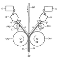
- the extrusion laminating apparatus shown in the figure includes two sets of extruders E, a die D communicating therewith, pre-rolls PR1 and PR2 disposed below an outlet D ′ of each die D, and a pair of laminating rolls CR1 and CR2.
- the molten resin fl is extruded downward from the outlet D ′ of both dies D, and comes into contact with the pre-rolls PR1 and PR2 that are freely rotatable (X1 direction, X1 ′ direction) below the outlet D ′ to be in a semi-molten state 2
- the resin of the layer is integrated so as to sandwich the metallic substrate BP conveyed downward (Y direction) between the two sets of dies D, and these are sandwiched by a pair of laminate rolls CR1 and CR2, and are semi-molten
- the resin in the state is cooled and solidified on the surface of the substrate BP, thereby manufacturing a resin-coated substrate in which the substrate BP is coated with the resin coatings FL and FL.
- the spatial distance: t between the outlet D ′ and the pre-rolls PR1 and PR2 can be shortened.
- the molten resin fl extruded from the outlet D ′ of the die D is actually drawn in the rotation direction of the pre-rolls PR1 and PR2, in other words, due to the tension to be drawn in the tangential direction of the pre-rolls PR1 and PR2.
- the molten resin fl Since the molten resin fl is drawn in an oblique direction inclined in the rotational direction from the vertically lower side, the actual air gap t1 (distance from the outlet D ′ to the contact points of the pre-rolls PR1 and PR2) of the molten resin fl becomes longer. Furthermore, by pulling the molten resin in an oblique direction in this way, so-called “meani” (resin deposit) tends to adhere to the exit of the die, and the surface of the coating resin has streak-like chipping and quality. It becomes the problem above.
- the die D is actually arranged with an inclination as shown in FIG. 13 in order to prevent the adhesion of the sealant to the die outlet while reducing the air gap as much as possible.
- the spatial distance t2 between the outlet D ′ and the pre-rolls PR1 and PR2 is made shorter than the spatial distance t1 shown in FIG.
- the temperature of the molten resin is controlled by the preset temperature of the pre-roll. From the viewpoint of the adhesion between the substrate and the molten resin, it is preferable to keep the temperature of the molten resin at the nip position of the laminating roll at a high temperature, but if the temperature of the molten resin is too high, The amount of neck-in in the space length between the pre-roll and the space length (t2 in FIG. 13) and the space length between the pre-roll and the laminate roll (t3 in FIG. 13) increases. Accordingly, it is desirable that the space length t3 between the pre-roll and the laminate roll is also short, but in practice, this spatial distance is limited by the relationship between the laminate roll diameter and the pre-roll diameter.
- the resin-coated substrate is produced by setting the exit width of the die or mold to be considerably larger than the width of the metal substrate, and therefore the amount of resin loss is large and the production speed is high.
- the reality is that it is restricted.
- the present invention has been made in view of the above-described problems, and is a resin in which a resin film is coated on the surface of a substrate by sandwiching a molten resin together with the substrate at a nip clamping portion of a pair of laminate rolls and cooling and solidifying the resin.
- Manufacturing apparatus and manufacturing method for manufacturing a coated substrate Production of a resin-coated substrate that is excellent in neck-in suppression effect and film sway suppression effect, and also in the suppression effect of maine in a trade-off relationship with neck-in suppression An object is to provide an apparatus and a manufacturing method.
- a resin-coated substrate manufacturing apparatus includes a molten resin extruded downward from an outlet opened on a lower end surface of a die, together with a metal substrate, positioned below the outlet.
- a pre-roll is provided between the outlet and the laminating roll, and the molten resin extruded from the outlet is grounded to the pre-roll and then sent between a pair of laminating rolls.
- a fluid chamber for providing fluid to a space between the lower pre-rolls the fluid chamber having an opposing surface facing the space and the pre-rolls;
- the fluid provided from the fluid chamber tends to be taken up while the molten resin existing in the space is displaced in the rotation direction of the pre-roll while flowing in the fluid flow path along the facing surface to the die side.
- the fluid pressure is applied in the direction of pushing back.
- a pre-roll is disposed between a die outlet and a pair of laminate rolls positioned below and sandwiching the molten resin, and pressure is applied to a space (air gap) between the die outlet and the pre-roll. It is equipped with a fluid chamber that provides fluid such as air, and the molten resin that is pushed out from the outlet and grounded to a rotatable pre-roll is pulled in the direction of rotation of the pre-roll and tries to deform in an oblique direction, for example.
- the posture of the molten resin in the space particularly in the vicinity of the die outlet, can be set to a posture extending vertically downward from the die outlet as much as possible.
- Neck-in can be suppressed by reducing the length of the molten resin in the space as much as possible while effectively suppressing it.
- a device capable of reducing the loss amount of the resin may occur in the process of coating the resin film on the plate surface to produce a resin-coated substrate. That is, by arranging a pre-roll between the die outlet and the laminate roll, the air gap can be shortened, so that both neck-in and film shaking can be suppressed. By providing fluid from the chamber, the air gap can be further shortened by bending the attitude of the molten resin being conveyed in a non-contact state as desired, and film fluctuations caused by air turbulence and draw resonance can be avoided. It is a device that can suppress the adhesion of the main body.
- the fluid chamber has a facing surface facing the space and the pre-roll described above, and the fluid provided from the fluid chamber flows through the fluid flow path along the facing surface to the die side and is pushed into the space.
- the molten resin is provided from the space to the pre-roll through the fluid flow so as to follow the alignment of the opposing surface, and is in a semi-molten state on the pre-roll surface, for example. Neck-in is suppressed, and the resin in a semi-molten state is transported downward and is sandwiched between the nips of a pair of laminate rolls that rotate together with a separately transported metal substrate, and the molten resin is cooled and solidified.
- a resin-coated substrate is produced by coating the surface of the substrate with a resin film.
- the fluid When the pre-rolled molten resin is pulled in the rotational direction of the pre-roll, the fluid conforms to the shape of the opposing surface. By receiving fluid pressure from the fluid flowing through the flow path, the molten resin in the space can form an extending posture along the facing surface.
- the fluid chamber is provided with a first heating unit for heating the fluid to adjust its temperature and generating a fluid whose temperature is adjusted.
- a second heating unit for adjusting the temperature of the pre-roll is provided.
- the temperature of the molten resin at the time of clamping at the nip clamping part between the laminate rolls is important, but in order to increase the adhesion between the substrate and the resin film, the gap between the pre-roll and the pair of laminate rolls is important. It is desirable to raise the temperature of the molten resin within a range in which excessive neck-in does not occur in this space.
- a measure to reduce the pre-roll diameter is preferable from the viewpoint of reducing geometric constraints, but the cooling ability of the pre-roll is also reduced. Therefore, a first heating unit such as a heater is provided in the fluid chamber, and the temperature of the fluid provided from the fluid chamber to the space is adjusted by heating. By providing the resulting fluid to the molten resin passing through the space, the cooling amount of the molten resin grounded on the pre-roll surface can be adjusted as desired.
- a second heating unit such as a heater is provided on the pre-roll, and the molten resin grounded here is heated on the surface of the pre-roll whose temperature has been adjusted, so that the cooling amount of the molten resin is similarly adjusted as desired.
- a second heating unit such as a heater is provided on the pre-roll, and the molten resin grounded here is heated on the surface of the pre-roll whose temperature has been adjusted, so that the cooling amount of the molten resin is similarly adjusted as desired.
- a third heating unit is provided between the pre-roll and the pair of laminate rolls, on the conveyance path where the molten resin is sent to the pre-roll while being grounded.
- the neck-in of the space from the die outlet to the pre-roll can be suppressed, and film shaking can be prevented.
- the pressure of the fluid chamber increases the adhesion of the molten resin on the surface of the pre-roll, and the molten resin is easily cooled due to the cooling effect of the chamber fluid.
- the neck-in suppressing effect is increased, the film shaking preventing effect is increased, and further, the laminating speed is improved.
- the temperature of the molten resin is too low, there is a risk that the adhesion between the substrate to be laminated and the resin film will be reduced.
- a third heating unit is provided in a space from the pre-roll to the nip pressing part of the pair of laminate rolls in order to guarantee the temperature of the molten resin at the nip pressing part.
- the third heating unit include a heater (including an IR heater) and an oven furnace.
- the opposing surface has a first region having a shape complementary to the roll surface of the pre-roll, and the upper end of the fluid chamber bent from the first region to the outlet side of the die.
- the fluid flow path includes a first flow path between the first area and the molten resin on the roll surface, a second area and a lower area of the outlet.
- a fluid passage cross-sectional width of the first fluid passage that is continuous with the second fluid passage and is located upstream of the fluid flow. It is preferably narrower than the channel.
- the channel cross-sectional width of the first channel continuous to the second channel is narrowed (the channel cross-section of the second channel is the internal channel of the fluid chamber). Is narrowed in comparison with that of the second channel), so that a throttling effect of the fluid flowing through the second flow path corresponding to the second region is obtained, and the second flow path is a cross section of the flow path reaching the upper end of the fluid chamber.
- the width the gap width from the facing surface to the pre-roll, more strictly, the gap width from the facing surface to the molten resin that is in close contact with the pre-roll and the fluid flows through
- the molten resin can be given self-stability against change.
- the molten resin moves in the direction of widening the cross-sectional width of the second flow channel due to disturbance (turbulence of the outside air, etc.).
- the flow rate from the fluid chamber increases due to the decrease in the flow path resistance of the flow path, and since the cross-sectional width of the first flow path is constant (the flow path resistance is constant), the pressure loss increases as the flow rate increases.
- the static pressure in the second flow path decreases and the second flow path of the molten resin returns to the direction of narrowing.
- the molten resin moves in the direction of narrowing the channel cross-sectional width of the second channel, the flow rate from the fluid chamber decreases due to an increase in the channel resistance of the fluid channel, and the flow of the first channel Since the cross-sectional width is constant (the flow path resistance is constant), the pressure loss is reduced by the increase in flow velocity, the static pressure in the second flow path is increased, and the second flow path of the molten resin is widened. Return to the direction. Thus, in the process in which the channel cross-sectional width changes in the second channel, the molten resin has self-stability with respect to this change.
- the channel resistance of the first channel is 0.3 times or more of the channel resistance of the second channel.
- the inlet (boundary with the first channel) and the outlet (second channel) of the second channel having channel resistance that fluctuates due to disturbance.
- Self-stability increases as the ratio of the static pressure difference between the inlet and outlet of the first channel having a constant channel resistance with respect to the difference in static pressure at the boundary of the fluid chamber and the upper end surface of the fluid chamber increases. That is, the larger the value of the channel resistance of the first channel / the channel resistance of the second channel in the steady state, the higher the self-stability of the second channel. That is, this ratio must be increased and adjusted so that at least the influence of the change in the static pressure is greater than the influence of the change in the radius of curvature.
- the self-stability can be evaluated by the magnitude of the pressure change amount when the pressure change occurs and the magnitude of the flow rate change amount with respect to the change in the channel cross-sectional width of the second channel.
- the chamber original pressure increases when the required static pressure at the inlet of the second flow path is the same.
- the channel cross-sectional width changes, the amount of change in the required static pressure is large, and the amount of change in the flow rate is small.
- the self-restoring force increases by increasing the channel resistance of the first channel.
- the channel resistance of the first channel is preferably high, but in the relational expression between the flow rate and the pressure loss, the channel resistance is proportional to the channel length and inversely proportional to the cube of the channel cross-sectional width. If the channel length of the first channel is increased, the channel resistance increases, but the position where the molten resin is pressed against the pre-roll by the pressure in the fluid chamber is far from the die outlet. That is, the molten resin comes in contact with the pre-roll surface in close contact and is disadvantageous from the viewpoint of cooling and solidifying, and the neck-in amount increases. On the other hand, reducing the channel cross-sectional width is effective because the channel resistance increases to the third power.
- the thickness of both end portions of the resin on the surface of the laminate roll is large, and the flow path cross-sectional width cannot be reduced.
- the neck-in is small. Since the thickness increase at both end portions of the resin on the pre-roll surface and the laminate roll surface is reduced, the cross-sectional width of the flow path can be reduced.
- the dimension of the channel cross-sectional width (a 1 ) it has been found that 1 mm or less is practically applied, and 0.5 mm or less is more preferable.
- the larger the value of the channel resistance of the first channel / the channel resistance of the second channel the better.
- the upper end surface of the fluid chamber forms a flat surface
- the radius of curvature of the second region of the opposing surface is an intersection with the upper end surface.
- the radius of curvature is set at the outlet side, that is, in the fluid chamber. It is necessary to increase toward the upper end side.
- the curvature radius of the second channel is increased by increasing the radius of curvature of the second region of the opposing surface toward the intersection with the upper end surface.
- the second region includes a curved portion that bends from the first region to the exit side of the die, and the curved portion continuously with the curved portion. It has a straight part perpendicular to the upper end surface.
- the static pressure at the outlet of the second flow path is atmospheric pressure
- p 2out is zero and r is infinite, that is, a straight line.
- the static pressure at the outlet of the second flow path can be adjusted to about atmospheric pressure by configuring the straight portion that is continuous with the curved portion and orthogonal to the upper end surface.
- the second region includes a curved portion that bends from the first region to the outlet side of the die, and a second portion continuous with the curved portion. And a linear portion that is inclined in a direction of enlarging the cross section of the flow path of 2 and away from the outlet and intersects the upper end surface.
- the dynamic pressure at the outlet of the second flow path When the dynamic pressure is not negligible near the outlet in the second flow path, that is, when the negative pressure at the outlet has a great influence on the extended posture of the molten resin in the space, the dynamic pressure at the outlet of the second flow path In order to reduce the dynamic pressure (flow velocity), the flow path at the outlet can be enlarged.
- the lower end surface of the die facing the outlet and the upper end surface of the fluid chamber are both flat, and the upper end surface of the fluid chamber and the die A fluid flow path extending along the facing surface extends between the lower end surfaces of the second flow path to further form a third flow path, and the fluid flowing through the third flow path is less than the third flow path. Is also discharged in a large downstream direction of the cross section of the flow path.
- the dynamic pressure can be reduced by increasing the channel cross-sectional width of the third channel toward the outlet side to increase the channel cross-section.
- the flow path cross-sectional area of the third flow path is adjusted so that the fluid pressure in the third flow path is greater than atmospheric pressure. It is what.
- the negative pressure on the molten resin near the outlet of the die is adjusted by adjusting the cross-sectional width of the third flow path that continues from the second flow path so that the fluid pressure in the third flow path is greater than atmospheric pressure. The influence of can be eliminated. In this case, since the generation of the negative pressure moves to the outlet position of the third flow path, the molten resin extending in the space is not affected by the negative pressure.
- fluids having at least two kinds of fluid pressures are provided from the fluid chamber, and are provided from an end region in the width direction of the fluid chamber.
- the fluid pressure of the fluid is adjusted to be relatively high compared to the fluid pressure of the fluid provided from the inner region.
- the fluid provided from the fluid chamber to the fluid flow path is actually in the middle of the flow path in the width direction of the molten resin in any of the first flow path, the second flow path, and the third flow path. It leaks outward from both ends of the resin coating (this is the width direction of the resin coating).
- the pressure in the end region in the width direction of the fluid chamber that is, the portion where both ends of the molten resin pass can be set to a high pressure with respect to the inner region.
- a fluid chamber width end region and an inner region thereof may be defined, and high pressure fluid may be provided from the fluid chamber width end region.
- the high-pressure air at both ends can replenish air that leaks from the end of each channel after the first channel. Furthermore, since the effect
- the fluid chamber includes an internal flow path and a cylindrical portion around the internal flow path, and the internal flow path faces the facing surface.
- a part of the end surface of the cylindrical portion communicates with the opening and serves as the second region of the opposing surface, and the end portion region in the width direction of the cylindrical portion includes one end surface of the cylindrical portion.
- An opening facing the portion and a separate flow path communicating with the opening are formed, fluid is provided from the internal flow path of the fluid chamber and flows through the fluid flow path, and the fluid flows from the separate flow path. Further fluid is provided to the flow path.
- a separate channel with a narrowed channel cross-section for providing a fluid independent of the fluid supplied from the fluid chamber and flowing through the fluid channel is provided in the end portion in the width direction of the cylindrical portion.
- the fluid provided from the above can replenish the air leaking from the end of each flow path after the second flow path, and ensure the static pressure necessary to balance the curvature radius and take-up tension of the molten resin. .
- the temperature of the fluid provided from the separate flow path is higher than the temperature of the fluid flowing through the fluid flow path. Is.
- the temperature of the fluid provided from the separate flow path By making the temperature of the fluid provided from the separate flow path relatively high, the temperature of the molten resin can be kept high, and the take-up tension in the entire width direction can be lowered.
- the fluid chamber is composed of an internal flow path and a cylindrical portion around the internal flow path, and two side surfaces in the width direction of the cylindrical portion.
- a roller is attached to the roller, and the roller is in contact with the pre-roller so as to be rotatable so as to guarantee at least a channel cross-sectional width of the first channel.
- rollers By arranging rollers on the two side surfaces (side plates) of the fluid chamber and allowing them to contact each other in a rotatable manner with the roll surface of the pre-roll, it is possible to ensure the cross-sectional width of the first flow path with high accuracy. Furthermore, the channel cross-sectional width of the first channel can be easily changed by adjusting the position of the roller.
- the present invention extends to a method for producing a resin-coated substrate, and the method for producing a resin-coated substrate according to the present invention is a method in which a molten resin extruded downward from an outlet opened on a lower end surface of a die is made of a metal.
- Resin-coated substrate for producing a resin-coated substrate in which a molten resin is cooled and solidified by being sandwiched between a pair of laminating rolls that are positioned below the outlet and rotated together with the substrate, and the surface of the substrate is coated with a resin film
- a pre-roll between the outlet and the laminating roll in the process of grounding the molten resin extruded from the outlet to the pre-roll and then feeding the molten resin between the pair of laminating rolls, A fluid is supplied from a chamber to a space between the outlet and the pre-roll below the outlet, and faces the space and the pre-roll of the fluid chamber.
- the fluid is flowed to the die side through a fluid flow path along the direction, and fluid pressure is applied in a direction to push back the molten resin existing in the space to be displaced in the rotation direction of the pre-roll.
- the molten resin is grounded to the pre-roll, and then the molten resin and the substrate are pressed between the laminate rolls, and the molten resin is cooled and solidified to produce a resin-coated substrate in which the surface of the substrate is coated with a resin film. is there.
- a method may be adopted in which a pressure is sandwiched between a pair of laminate rolls in a sandwiched posture.
- the fluid is heated to adjust its temperature, and the heated temperature-controlled fluid is provided from the fluid chamber to the space, or the pre-roll is heated to adjust the surface temperature. It is preferable that the molten resin is grounded to the pre-roll surface that is heated and adjusted.
- the opposing surface includes a first region that has a complementary shape to the roll surface of the pre-roll, and a second region that bends from the first region to the outlet side of the die and reaches the upper end of the fluid chamber.
- the fluid flow path is between the first flow path between the first area and the molten resin on the roll surface, and between the second area and the molten resin in the space below the outlet.
- the flow path cross-sectional width of the 1st flow path which consists of a 2nd flow path and is continuous with the 2nd flow path is narrow compared with the internal flow path of the fluid chamber which is an upstream of the flow of a fluid. Is preferred.
- the upper end surface of the fluid chamber forms a flat surface, and the radius of curvature of the second region of the opposing surface increases toward the intersection with the upper end surface, and the molten resin extruded from the outlet While applying the fluid pressure, the molten resin is allowed to reach the roll surface along the second region via the second flow path after extending to the space below. It is preferable to adhere to the roll surface along the first region via one flow path.
- the second region is orthogonal to the upper end surface, and the molten resin is applied while applying the fluid pressure to the molten resin extruded from the outlet. Is extended vertically downward in the space to reach the roll surface along the second region via the second flow path, and the first flow path via the first flow path. It may be in close contact with the roll surface so as to follow the region.
- the second region has a curved portion that bends from the first region to the outlet side of the die, and a straight portion that is continuous to the curved portion and orthogonal to the upper end surface. It may be.
- the second region includes a curved portion that bends from the first region to the outlet side of the die, and a flow of the second flow path continuously to the curved portion. It may have a straight portion that is inclined in the direction of increasing the road cross section and away from the exit and intersecting the upper end surface.
- the lower end surface of the die facing the outlet and the upper end surface of the fluid chamber are both flat, and the upper end surface of the fluid chamber and the lower end surface of the die are formed.
- a fluid channel extending along the opposing surface extends to form a third channel, and a fluid is allowed to flow through the third channel next to the second channel.
- the fluid may be discharged in a downstream direction having a larger flow path cross section than the path.
- the flow path cross-sectional area of the third flow path may be adjusted so that the fluid pressure in the third flow path is greater than atmospheric pressure.
- the flow path resistance of the first flow path may be adjusted to 0.3 times or more the flow path resistance of the second flow path.
- At least two kinds of fluid pressure fluids are provided from the fluid chamber, and the fluid pressure of the fluid provided from the end region in the width direction of the fluid chamber. May be adjusted so as to have a relatively high pressure compared to the fluid pressure of the fluid provided from the inner region.
- the fluid chamber is composed of an internal flow path and a cylindrical portion around the internal flow path, and the internal flow path communicates with an opening facing the opposing surface, and A part of the end surface of the cylindrical part is the second region of the opposing surface, and an opening facing the part of the end surface of the cylindrical part is formed in the end region in the width direction of the cylindrical part.
- a separate flow channel is formed, and fluid is supplied from the internal flow channel of the fluid chamber to the fluid flow channel, and further fluid is supplied from the separate flow channel to the fluid flow channel. You may do.
- the temperature of the fluid provided from the separate flow path is set higher than the temperature of the fluid flowing through the fluid flow path.
- the fluid chamber is composed of an internal flow path and a cylindrical portion around the internal flow path, and rollers are attached to two side surfaces in the width direction of the cylindrical portion. It is preferable that the roller is in contact with the pre-roller so as to be rotatable so as to ensure at least the channel cross-sectional width of the first channel.
- a pre-roll is arranged between the lower part of the die outlet and the pair of laminate rolls, and between the pre-roll and the die outlet.
- the fluid provided from the fluid chamber is caused to flow along the fluid flow path along the facing surface of the fluid chamber facing the space and the pre-roll, and the molten resin existing in the space is displaced in the rotation direction of the pre-roll and is taken up.
- the molten resin extruded vertically downward from the outlet can be extended vertically downward as much as possible.
- the length of the existing molten resin can be made as short as possible. Therefore, while exhibiting a high neck-in suppressing effect, it is possible to effectively suppress film fluctuations, and it is also possible to effectively suppress the mains in a trade-off relationship with this neck-in suppression.
- FIG. 2 is an enlarged view of part II of FIG. 1 showing an embodiment of a space between a die outlet and a pre-roll and a fluid chamber, wherein (a) is a melting of the space between the die outlet and the pre-roll. It is a figure explaining the state which the fluid pressure of the fluid which flows through a fluid flow path acts in the direction which pushes back deformation
- (A) is a figure explaining other embodiment of the fluid chamber, (b) is a bb arrow line view of (a).
- (A) is the figure explaining further another embodiment of the fluid chamber, (b) is a bb arrow line view of (a).
- (A) is the figure explaining further another embodiment of the fluid chamber, (b) is a bb arrow line view of (a). It is the figure explaining one Embodiment of the manufacturing apparatus of the conventional resin coating board
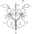
- FIG. 1 is a schematic view showing an embodiment of the apparatus for producing a resin-coated substrate of the present invention.
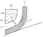
- FIG. 2 is an enlarged view of a portion II in FIG. 1, and a space between a die outlet and a pre-roll and a fluid chamber.
- FIG. 2A is a diagram showing an embodiment of the present invention, in which FIG. 2A shows a state in which the fluid pressure of the fluid flowing through the fluid flow path acts in a direction to push back the deformation of the molten resin in the space between the die outlet and the preroll
- FIG. 2B is a view taken along the line bb in FIG. 2A.
- the illustrated manufacturing apparatus 10 includes an extruder 2 that extrudes molten resin, a die 1 that communicates with the extruder 2 and has an outlet 1a having a predetermined width, and is positioned below the die 1 at a predetermined rotational speed.
- a resin which is freely rotatable (X2 direction, X3 direction) and the molten resin sent and the metal substrate BP are sandwiched, the molten resin fl is cooled and solidified, and the resin film FL is coated on the surface of the substrate BP.
- the fluid providing unit 7 includes a compressor 6 that forms pressure air and a fluid chamber 5 that provides pressure air.
- the fluid chamber 5 includes a rectangular frame-shaped cylindrical portion (top plate 5a, side plate 5b, bottom plate 5c) and a central flow path 5d.
- the pre-roll 3A is formed.
- the side facing surface has a complementary shape to the pre-roll 3A.
- the opposed surface of the top plate 5a of the cylindrical portion facing the pre-roll 3A and the space K is substantially linear (including both curved and straight lines) having a complementary shape to the pre-roll 3A.
- the first region 5a1 and the second region 5a2 which is bent from the first region 5a1 to the outlet 1a side of the die 1 and is orthogonal to the upper end surface 5a3 of the fluid chamber 5.
- intersection of the second region 5a2 and the upper end surface 5a3 orthogonal to each other is disposed at a position set back by a predetermined width with respect to the outlet 1a facing the flat lower end surface 1b of the die 1.
- the molten resin fl extruded downward from the outlet 1a extends through the space K, contacts the pre-roll 3A, and is further pressed downward and pinched together with the substrate BP by the pair of laminating rolls 3B and 3C.
- a resin-coated substrate in which a resin film FL formed by cooling and solidifying fl covers the substrate BP is manufactured.
- the fluid fd generated by the compressor 6 is provided from the internal flow path 5d to the molten resin fl on the surface of the pre-roll 3A.
- the fluid fd is provided between the molten resin fl and the fluid chamber 5.
- the gap S fluid channel
- the fluid fd flowing upward applies a fluid pressure p to the molten resin fl extending into the space K below from the outlet 1a in the process of flowing through the fluid flow path along the facing surface, thereby exiting the outlet 1a.
- the molten resin extruded vertically downward in the space K in the vicinity of the outlet 1a extends vertically downward, and reaches the roll surface along the second region 5a2 via the fluid flow path. Then, it closely adheres to the roll surface along the first region 5a1 via the fluid flow path.
- FIG. 3 shows another embodiment of the resin-coated substrate manufacturing apparatus of the present invention.
- the illustrated manufacturing apparatus 10 ⁇ / b> A includes two extruders 2 and two dies 1 that communicate with the extruder 2, and further includes a corresponding pre-roll 3 ⁇ / b> A below each die 1.
- the molten resin fl extruded downward from the outlet 1a of each die 1 contacts the corresponding pre-roll 3A, and the semi-molten resin fl after contacting the two pre-rolls 3A passes between the two dies 1 and 1. It is sent between a pair of laminating rolls 3B and 3C so as to sandwich both sides of the substrate BP conveyed downward (Y direction), and is sandwiched between the substrates BP and resin coatings FL and FL on both sides thereof. A substrate is manufactured.
- FIG. 4 shows another embodiment of the apparatus for producing a resin-coated substrate of the present invention.
- the illustrated manufacturing apparatus 10 ⁇ / b> B includes a fluid chamber 5 in which a first heating unit 8 ⁇ / b> A such as a heater is built.
- the fluid fd generated by the compressor 6 by the first heating unit 8A can be adjusted to a desired heating temperature, and the heated temperature-controlled fluid can be provided to the molten resin fl in the space K.
- the first heating unit 8 ⁇ / b> A is built in the compressor 6 in addition to being built in the fluid chamber 5, and is built in a flow path connecting the compressor 6 and the fluid chamber 5. It may be.
- the nip of the laminate rolls 3B and 3C is suppressed by suppressing the excessive cooling of the molten resin by the heated temperature-controlled fluid. It is possible to control the temperature of the molten resin fl in the clamping portion so as to be a temperature necessary for the substrate BP and the resin coating FL to be integrated with high adhesion.
- FIG. 5 shows another embodiment of the resin-coated substrate manufacturing apparatus of the present invention.
- the illustrated manufacturing apparatus 10 ⁇ / b> C includes a pre-roller 3 ⁇ / b> A in which a second heating unit 8 ⁇ / b> B such as a heater is built.
- the temperature of the molten resin fl at the nip clamping portion of the laminate rolls 3B and 3C is such that the substrate BP and the resin coating FL have a high adhesion force by the second heating unit 8B built in the pre-roll 3A.
- the temperature can be controlled to be necessary for integration.
- FIG. 6 shows another embodiment of the apparatus for producing a resin-coated substrate of the present invention.
- the manufacturing apparatus 10D shown in the figure is between a pre-roll 3A and a pair of laminating rolls 3B and 3C, and a heater (including an IR heater) or an oven is placed on a conveying path that is grounded to the pre-roll 3A and the molten resin fl is sent downward.
- a third heating unit 9 such as a furnace is provided.
- a third heating unit 9 is provided in the space from the pre-roll 3A to the nip pressing portions of the pair of laminate rolls 3B and 3C. Thereby, the high adhesive force between a board
- 6 may be a separate manufacturing apparatus in which the first heating unit 8A shown in FIG. 4 and the second heating unit 8B shown in FIG. 5 are further applied to the manufacturing apparatus 10D shown in FIG.
- FIG. 8 is a figure explaining that a local convex part is formed in molten resin in a 2nd flow path.
- the fluid flow path is such that the gap S area corresponding to the first area 5a1 on the opposite surface is the first flow path, and then the gap S area corresponding to the second area 5a2 is the second flow path.
- the gap between the upper end surface 5a3 of the fluid chamber 5 and the lower end surface 1b of the die 1 is a third flow path.
- r radius of curvature of the opposite surface of the inlet of the second channel corresponding to the second region
- A position of the inlet of the first channel
- B of the first channel Channel outlet position (or channel inlet position of the second channel)
- C Channel outlet position of the second channel (or channel inlet position of the third channel)
- D Third flow Channel outlet position of the channel
- p C chamber pressure
- p 0 atmospheric pressure
- p 2in channel inlet pressure of the second channel
- Q flow rate
- T take-up tension
- L 1 length
- a 1 channel cross-sectional width (gap)
- v 1 Flow velocity
- Re 1 Reynolds number
- a 2 Flow path cross-sectional width (gap)
- the molten resin fl facing the second flow path has a curved surface, it is rigid and local unevenness is unlikely to occur.
- the radius of curvature of the base portion of the convex portion fl ′ must be negative. I must. At this time, a portion with a negative curvature radius cannot exist due to the pressure of the second flow path, and the curvature radius becomes large and gentle.
- the flow path cross-sectional width a2 of the second flow path is increased, but the molten resin fl moves in a direction in which the flow path cross-sectional width of the second flow path becomes narrower due to self-restoration to be described later.
- the road cross section width a 2 returns to the curvature radius r + a 2 .
- the radius of curvature of the molten resin fl along the second flow path can be set in a wide range, and the smaller the radius of curvature, the smaller the distance from the exit 1a of the die 1 to the pre-roll 3A, Neck-in can be effectively suppressed.
- the cross-sectional width of the first flow path continuous to the second flow path is narrowed, a throttling effect of the fluid fd flowing through the second flow path corresponding to the second region 5a2 is obtained.
- the molten resin can be provided with self-stability against this change.
- the pressure of the fluid provided from the fluid chamber 5 is constant and the molten resin moves in the direction of widening the cross-sectional width of the second flow path due to disturbance (turbulence of outside air, etc.)
- the flow rate from the fluid chamber 5 increases due to the decrease in the flow path resistance of the fluid flow path, and the flow path cross-sectional width of the first flow path is constant (the flow path resistance is constant).
- the static pressure in the second flow path increases, and the second flow path of the molten resin returns to the direction of narrowing.
- the molten resin moves in the direction of narrowing the channel cross-sectional width of the second channel, the flow rate from the fluid chamber decreases due to an increase in the channel resistance of the fluid channel, and the flow of the first channel Since the cross-sectional width is constant (the flow path resistance is constant), the pressure loss is reduced by the increase in flow velocity, the static pressure in the second flow path is increased, and the second flow path of the molten resin is widened. Return to the direction. Thus, in the process in which the channel cross-sectional width changes in the second channel, the molten resin has self-stability with respect to this change.
- the original pressure in the chamber becomes the pressure in the second channel.
- the molten resin moves in the direction in which the channel cross-sectional width increases, and the self-stability of the fluid channel is lost. For this reason, the 1st flow path by which the cross-sectional width of the flow path was narrowed with respect to the stability of the fluid flow path is a necessary condition.
- the channel cross-sectional width of the second channel is increased, the radius of curvature of the molten resin is increased, and the take-up tension is balanced with a small static pressure.
- the first flow is set so that the decrease in the static pressure in the second flow path is larger than the decrease in the required static pressure due to the increase in the radius of curvature of the molten resin. What is necessary is just to determine the shape of both a path
- the first flow path makes it possible to reduce the flow rate flowing through the flow path, and the effect of preventing film shaking is also enhanced.
- the inlet B (boundary with the first channel) and the outlet C (second channel) of the second channel whose channel resistance varies due to disturbance
- the self-stability can be evaluated by the magnitude of the pressure change amount when the pressure change occurs and the magnitude of the flow rate change amount with respect to the change in the channel cross-sectional width of the second channel.
- the first flow path the flow path resistance of the second flow path is increased, if necessary static pressure at the inlet B of the second channel are the same, the chamber base pressure p C increases, the second If the flow path cross-sectional width a 2 of the flow path is changed, the pressure variation of the required static pressure is large, the variation of the flow rate is small.
- the self-restoring force increases by increasing the channel resistance of the first channel.
- the channel resistance of the first channel is preferably high, but in the relational expression between the flow rate Q and the pressure loss, the channel resistance is proportional to the channel length and inversely proportional to the cube of the channel cross-sectional width. If the channel length L1 of the first channel is increased, the channel resistance increases, but the position where the molten resin is pressed against the pre-roll 3A by the pressure in the fluid chamber 5 is far from the die outlet 1a. . That is, the molten resin comes in contact with the surface of the pre-roll 3A and comes into close contact with it, which is disadvantageous from the viewpoint of cooling and solidifying, and the neck-in amount increases.
- the channel cross-sectional width a 1 is effective because the channel resistance increases to the third power.
- the thickness of both end portions of the resin on the surface of the laminate roll is large, and the cross-sectional width of the flow path cannot be narrowed. can be narrowed the passage cross-sectional width a 1 since the thickness increment of the end portions of the resin 3A surface and laminating roll 3B surface decreases.
- the dimensions of the flow path cross-sectional width a 1 is applied practically 1mm or less, it is confirmed that more preferably 0.5mm or less.
- the larger the value of the channel resistance of the first channel / the channel resistance of the second channel the better, but it is desirable to ensure 0.3 times or more practically.
- the radius of curvature r is set to the outlet. It is necessary to increase toward the side, that is, the intersection with the upper end surface 5a3 of the fluid chamber 5.
- r radius of curvature (m) of second channel
- a 2 channel cross-sectional width (m) of second channel
- r + a 2 radius of curvature of molten resin (m)
- T unit flow Take-up tension per road section width (N / m)
- p 2in static pressure at the inlet of the second channel (Pa)
- p 2out static pressure at the outlet of the second channel (Pa)
- L 2 Length of the second flow path
- x distance from the inlet in the second flow path (0 ⁇ x ⁇ L 2 )
- Equation 2 if the static pressure at the outlet C of the second flow path is atmospheric pressure, p 2out becomes zero and r becomes infinite, that is, a straight line.
- the second flow path is formed by configuring the facing surface of the curved portion 5a2 ′ and the straight portion 5a2 ′′ that is continuous with the curved portion 5a2 ′ and orthogonal to the upper end surface 5a3.
- the static pressure at the outlet C can be adjusted to about atmospheric pressure.
- the second flow path In order to reduce the dynamic pressure at the outlet C, the dynamic pressure (flow velocity) can be reduced by expanding the flow path at the outlet C. That is, the second region on the opposite surface of the fluid chamber 5B shown in FIG. 7c is a curved portion 5a2 ′ that bends from the first region to the outlet 1a side of the die 1 and the curved portion 5a2 ′ continues to the second region.
- the straight line portion 5a2 ′ ′′ that inclines in the direction of enlarging the cross section of the flow path and away from the outlet 1a and intersects the upper end surface 5a3.
- a third flow path is formed between the flat lower end face 1b of the die 1 and the flat upper end face 5a3 of the fluid chamber 5, and the fluid flowing through the fluid flow path is Then, after flowing through the third flow path, it is discharged to the downstream side having a flow path cross-sectional width larger than that of the third flow path and communicating with the atmosphere (released fluid fd1 in FIG. 2).
- the dynamic pressure flow velocity
- the dynamic pressure can be reduced by increasing the channel cross-sectional width a3 of the third channel toward the outlet D side to increase the channel cross-section.
- the flow path cross-sectional area of the third flow path is adjusted such that the fluid pressure in the third flow path is greater than the atmospheric pressure.
- the channel cross-sectional width a 3 of the third channel continuing from the second channel the channel cross-sectional area is adjusted, and the influence of the negative pressure on the molten resin in the vicinity of the outlet 1a of the die 1 is affected. It can be lost. In this case, since the generation of the negative pressure moves to the outlet D side of the third flow path, the molten resin extending in the space K is not affected by the negative pressure.
- the adjustment of the fluid pressure p, the rotation speed of the laminate rolls 3B and 3C, the extrusion speed of the molten resin, and the like can be adjusted by a control computer (not shown).
- a device that illustrates a CCD camera or a video camera that can visually recognize the extended orientation (such as the vertical direction) of the molten resin in the space K may be provided.
- the laminate roll is rotated at a predetermined rotational speed.
- the molten resin fl is quickly pressed against and closely adhered to the pre-roll 3A by the fluid pressure p provided by the pressure fluid fd provided from the air chamber 5, so that it is in a semi-molten state, thereby being approximately the same as the width of the extruded molten resin fl. It is possible to guarantee the production of the resin coating FL having a width of.
- the resin material for the resin coating is not particularly limited.
- polyolefin, polyester, polyamide, modified products or mixtures thereof, which are thermoplastic resin trees that exhibit fluidity when heated, are applied. it can.
- FIGS. 9, 10, and 11 are diagrams for explaining other embodiments of the fluid chamber.
- the fluid chamber 5C shown in FIG. 9 has a flow path inside thereof defined in three sections, and is composed of flow paths 5e and 5e in the width direction end region of the fluid chamber 5C, and an internal region 5d inside thereof.
- the fluid pressure of the fluid provided from the flow path 5e in the width direction end region is adjusted to be relatively high compared to the fluid pressure of the fluid provided from the internal region 5d to the fluid flow path.
- the fluid provided from the fluid chamber to the fluid flow path is actually in the middle of the flow path in the width direction of the molten resin in any of the first flow path, the second flow path, and the third flow path. It leaks outward from both ends of the resin coating (this is the width direction of the resin coating).
- the neck-in occurs at the both ends of the molten resin, the molten resin film becomes thick, and the take-up tension increases accordingly. Therefore, the pressure in the end region in the width direction of the fluid chamber, that is, the portion through which both ends of the molten resin pass can be set to a high pressure with respect to the inner region.
- the high-pressure fluid at both ends provided from the channel 5e in the width direction end region can replenish the air leaking from the end of each channel after the first channel.
- pressure is also show
- the fluid chamber 5D shown in FIG. 10 is provided with a channel 5f separate from the internal channel 5d in the end region in the width direction of the cylinder portion.
- An opening is provided in the middle of the second region 5a2 so as to face the facing surface.
- a separate channel 5f having a narrowed channel cross section for providing a fluid independent of the fluid supplied from the fluid chamber and flowing through the fluid channel is provided in the end portion in the width direction of the cylindrical portion.
- the fluid provided from the channel 5f supplements the air leaking from the end of each channel after the second channel and secures the static pressure required to balance the curvature radius and take-up tension of the molten resin. Can do.
- the temperature of the fluid provided from the separate flow path 5f relatively high, the temperature of the molten resin can be kept high, and the take-up tension in the entire width direction can be lowered. .
- a roller 5g is attached to two side plates 5b in the width direction of the cylindrical portion, and the roller 5g is rotatably contacted with the pre-roll 3A so that at least the flow path of the first flow path.
- the cross-sectional width is guaranteed.
- the roller 5g can ensure the channel cross-sectional width in the first flow path with high accuracy, and the flow path cross-sectional width of the first flow path can be easily changed by adjusting the position of the roller 5g. can do.
- the take-up tension of the molten resin is generally determined by the resin and its molding conditions, and this value can be measured with a commercially available capillary rheometer or the like.
- the specification of the apparatus can be determined by calculation if the take-up tension is known, the inventors performed various calculations shown below.
- the pressure loss ⁇ p 1 in the first flow path is The dynamic pressure p v due to the flow velocity v in the first channel and the second channel is Thus the original pressure p c in the chamber, Thus, if the take-up tension of the molten resin is measured, the pressures in the first channel, the second channel and the fluid chamber can be determined.
- the relationship between the chamber source pressure p c , the first channel pressure loss ⁇ p1, the second channel pressure loss ⁇ p2, and the second channel velocity (fluid outlet velocity) is as follows.
- the radius of curvature of the molten resin becomes large and balances with the take-up tension with a small static pressure. Since the decrease in the static pressure of the second flow path is larger than the decrease in the required static pressure due to the increase in the radius of curvature of the molten resin when the cross-sectional width of the flow path is widened, the molten resin is in the second flow path. It was confirmed that the channel cross-sectional width returned to the direction of narrowing. In this way, the shapes of the first flow path and the second flow path may be determined so that the self-restoring force can be maintained.
- a third flow path having a length L 3 and a fluid cross-sectional width a 3 is added to separate the atmosphere release position from the molten resin. Can do.
Landscapes
- Engineering & Computer Science (AREA)
- Mechanical Engineering (AREA)
- Extrusion Moulding Of Plastics Or The Like (AREA)
Abstract
ネックイン抑制効果と膜揺れ抑制効果に優れ、さらに、ネックインの抑制とトレードオフの関係にあるメヤニの抑制効果にも優れた樹脂被覆基板の製造装置および製造方法を提供する。 ダイ1の出口1aから下方に押出された溶融樹脂flを基板BPとともに下方の一対のラミネートロール3B,3C間で挟圧し、基板BPを樹脂被膜FLが被覆してなる樹脂被覆基板を製造する製造装置10であり、出口1aとラミネートロール3B,3Cの間にプレロール3Aを備え、出口1aとプレロール3Aの間の空間Kに流体fdを提供する流体チャンバー5をさらに備え、流体チャンバー5から提供された流体fdは、空間Kおよびプレロール3Aに対向する対向面に沿う流体流路をダイ1側に流れながら、空間K内に存在する溶融樹脂flがプレロール3Aの回転方向に変位して引取られようとするのを押し戻す方向に流体圧pを付与させるようになっている。
Description
本発明は、樹脂を溶融してダイから押出し、押出された溶融樹脂と基板を一対のラミネートロールで挟圧することによって基板が樹脂被膜にて被覆された樹脂被覆基板を製造する製造装置と製造方法に関するものである。
樹脂を溶融してダイから押出し、押出された溶融樹脂と基板を一対のラミネートロールで挟圧することによって基板が樹脂被膜にて被覆された樹脂被覆基板(押出しラミネート材)を製造するに当たり(いわゆる押出しラミネート成形)、ダイの出口から押出された溶融樹脂は、その下方の一対のラミネートロールのニップ挟圧部に至るまでの空間(エアギャップ)において自由表面でその形が形成される伸長流動変形を受けることが一般に知られている。そして、この伸長流動変形の際には、溶融樹脂がネックインと呼ばれる、幅が狭くなる挙動を示すことが往々にしてある。このネックインによって樹脂被膜の端部は中央部に比して相対的に厚くなってしまうことが知られている。
この樹脂被覆のネックインについてより詳細に説明するに、これは、ダイの出口から押出された溶融樹脂が一対のラミネートロールに到達し、ここで基板とともに挟圧されて冷却固化されるまでの間で発生する。厳密には、このネックインの発生は以下のような、溶融樹脂の流動形態の相違に起因するものである。
すなわち、溶融樹脂の流動形態は、幅固定された部分である樹脂被膜の中央部(製品となる部分)が平面伸長流動となり、その長手方向のみならずその幅方向にも力が作用する。
一方、樹脂被膜の両端部の流動形態は自由に縮む一軸伸長流動となるが、これに加えて、樹脂被膜中央部の平面伸長流動のうちの幅方向への流動による力を受けてネックインが生じる。このネックインの発生によって、樹脂被膜の幅方向で厚みの分布が生じてしまい、その両端部が自由に縮むことによって該両端部では厚くなる部分が発生してしまう。
さらに、樹脂被膜の両端部は、その一軸伸長流動と中央部の平面伸長流動の境界において、双方からの圧力を受けて薄くなってしまうこともある。
このように、ネックインが生じることによって樹脂被膜の端部は中央部に比して相対的に厚くなってしまうことから、従来の製造装置では、均一な厚みの被覆樹脂で基板がラミネートされた樹脂被覆金属板を製造するには、ダイもしくは金型の出口幅を樹脂被覆される金属板よりもかなり大きな寸法に設定しておかなければならなかった。このネックイン量の増大にともなって成形された樹脂被膜の両端部の厚みも大きくなり、トリム除去される樹脂量が増加することで樹脂の利用効率の低下が一層助長されることになってしまう。
押出しラミネート成形によって樹脂被覆基板を製造する場合、ダイもしくは金型の出口とラミネートロールのニップ位置との空間には一般にエアギャップが形成される。そして、押出しラミネート成形では、一対のラミネートロールが使用されること、ラミネートロールのニップ位置には溶融樹脂のほかに金属素材の基板も供給されること、などから幾何学的な制約のためにエアギャップの短縮には自ずと限界がある。
ところで、エアギャップが長い場合にドローレゾナンスと呼ばれる膜揺現象が発生し、この現象によってネックイン量が周期的に変化し、被覆樹脂の厚みも同様に周期的に変動することで膜厚が不均一になるという問題もある。特にラミネート速度を上げた場合にこの膜揺現象が顕著になることが一般に知られている。なお、この膜揺現象は、ドロー比(ダイ出口隙間/被覆樹脂厚み)が大きい場合に発生し易いこともまた知られている。
ここで、従来の公開技術に目を転じるに、溶融膜のネックインを抑制し、かつ膜揺れを防止する技術として、エアギャップの溶融膜の両端部に高圧気体を吹き付ける技術が特許文献1に開示されている。しかし、この技術では高圧気体の動圧を利用しているために、高圧気体の吹出し方向や吹き出し量の調整が困難であり、吹き出された気体によって膜揺れが誘発され、助長されてしまう危険性がある。
一方、特許文献2には、エアギャップの溶融膜の両端部を吸引する技術が開示されている。しかし、この技術では溶融樹脂がネックインする力とバランスするように吸引力の調整が必要となり、ラミネート部周辺の気圧や気流の乱れ等の外乱に対して安定性に欠ける。すなわち、一旦バランスが崩れるとネックイン防止効果は無くなってしまい、再度の装置調整が必要になり、金属基板や樹脂の損失量が多くなってしまう。
なお、これら特許文献1、2で開示される技術はいずれも、エアギャップを積極的に短くするものではなく、長いエアギャップを許容しながらも如何にしてネックインを抑制するかを課題とするものである。
さらに、特許文献3には、プレロールをダイもしくは金型の出口とラミネートロールの間に配置した技術が開示されている。この技術は、エアギャップ内にプレロールと呼ばれる金属冷却ロールを配し、溶融樹脂膜をまずプレロールで受け、次いでラミネートロールへ供給することによって過大なネックインを抑制し、膜揺れの発生を防止するものである。この技術は、プレロールによって溶融樹脂膜を一旦冷却して半溶融樹脂膜とし、この半溶融樹脂膜をラミネートロールに供給するものである。
このプレロールを利用した技術は、ダイもしくは金型と、一対のラミネートロールと、からなる製造装置の中を溶融樹脂膜や金属基板が通過する幾何学的に制限された空間において、最も実用的な手法の一つと言える。しかしながら、特許文献3に開示された技術を適用した場合であっても、ダイもしくは金型の出口からプレロールまでの間でネックインは依然として大きく発生することが本発明者等によって特定されている。これは、ダイの出口からプレロールまでの間の空間距離が長くなることが大きな要因である。
ここで、従来の押出ラミネート装置を図12を参照して説明する。図示する押出ラミネート装置は、2組の押出機Eとこれに通じるダイDと、それぞれのダイDの出口D’の下方に配設されたプレロールPR1,PR2と、一対のラミネートロールCR1,CR2とから大略構成されている。双方のダイDの出口D’から溶融樹脂flが下方に押出され、出口D’の下方に回転自在(X1方向,X1’方向)なプレロールPR1,PR2に接地して半溶融状態となった2層の樹脂が、2組のダイDの間を下方(Y方向)に搬送される金属性の基板BPを挟むようにして一体とされ、これらが一対のラミネートロールCR1,CR2で挟圧され、半溶融状態の樹脂が基板BPの表面で冷却固化されることにより、樹脂被膜FL,FLで基板BPが被覆されてなる樹脂被覆基板を製造するものである。
同図で示すように、ダイDの出口D’をプレロールPR1,PR2の頂点の上方に配置することにより、出口D’とプレロールPR1,PR2の間の空間距離:tを短くすることができる。しかしながら、ダイDの出口D’から押出された溶融樹脂flは、実際にはプレロールPR1,PR2の回転方向へ引き取られることから、言い換えれば、プレロールPR1,PR2の接線方向へ引取ろうとする張力によって、溶融樹脂flが鉛直下方から回転方向へ傾斜した斜め方向で引き取られるために、実際の溶融樹脂flのエアギャップ:t1(出口D’からプレロールPR1,PR2の接地点までの距離)は長くなる。さらに、このように斜め方向に溶融樹脂が引っ張られることでダイの出口にいわゆるメヤニ(樹脂付着物)が付着し易くなってしまい、また、被覆樹脂表面にはスジ状の欠けが発生して品質上の問題となってしまう。
このような観点から、可能なかぎりエアギャップを短縮しながら、ダイの出口へのメヤニの付着を防止することを可能とするべく、実際には図13で示すようにダイDを傾斜させて配置し、出口D’とプレロールPR1,PR2の間の空間距離:t2を図12で示す空間距離:t1よりも短くするようにしている。
しかしながら、図13のようなダイ配置を適用したとしても依然として、プレロールの外径やダイの外形などによる幾何学的な制約から、エアギャップt2の短縮に限界があることに変わりはなく、エアギャップを短縮することとメヤニの抑制はトレードオフの関係になっている。このため、ダイDの出口D’とプレロールPR1,PR2の間の空間長さt2は長くなってしまい、この空間でのネックインの増加を抑制し切れていないのが現状である。
ところで、溶融樹脂の温度は、プレロールの設定温度によって制御されている。基板と溶融樹脂の密着力の観点で言えば、ラミネートロールのニップ位置における溶融樹脂の温度を高温に保持した方が密着力の向上には好ましいものの、溶融樹脂の温度が高すぎると、ダイ出口とプレロールの間の空間長さ(図13中のt2)、およびプレロールとラミネートロールの間の空間長さ(図13中のt3)におけるネックインの量が増加してしまう。したがって、プレロールとラミネートロールの間の空間長さt3も短い方が望ましいが、実際にはこの空間距離はラミネートロール径やプレロール径の関係から制約されることになる。
上記する空間長さt2、t3をできるだけ短くするためには、プレロールの外径を小さくすればよいことは理解に易いが、プレロールの外径を小さくすることによってプレロールの冷却能力は小さくなってしまい、プレロール表面での溶融樹脂温度は高くなってしまう。溶融樹脂温度が必要以上に高いと、空間長さt2、t3でのネックイン量が大きくなってしまう。また、ネックインが増加するとともに、特に高速ラミネートの際には、膜揺れの発生から生産速度を制限しなければならなくなる。さらに、プレロールの外径が極端に小さく、その冷却能力が大きく不足すると、プレロールに対して溶融樹脂が融着してしまい、ラミネートロールへの提供ができなくなってしまう。逆にプレロール径を大きくした場合は、空間長さt2、t3がともに長くならざるを得ず、ネックインが増加することは必至である。
このように、現状の押出しラミネート成形では、ダイもしくは金型の出口幅を金属基板の幅よりもかなり大きく設定して樹脂被覆基板を生産しており、したがって樹脂のロス量が多く、生産速度が制限されているのが実態である。
以上より、ダイ出口から押し出されてプレロールの表面に接地するまでの溶融樹脂の長さ(空間距離)を可及的に短くすることによって高いネックイン抑制効果を奏するとともに、膜揺れを効果的に抑制することができ、さらには、ネックインの抑制とトレードオフの関係にあるメヤニも効果的に抑制することのできる技術の開発が当該分野において切望されている。
さらに、ネックインを抑制しながら、基板と樹脂被膜との密着力を確保するために溶融樹脂の温度を広範囲に精度よく制御することのできる技術の開発が切望されている。
本発明は上記する問題に鑑みてなされたものであり、溶融樹脂を一対のラミネートロールのニップ挟圧部で基板とともに挟圧し、冷却固化することによって基板の表面に樹脂被膜が被覆してなる樹脂被覆基板を製造する製造装置と製造方法に関し、ネックイン抑制効果と膜揺れ抑制効果に優れ、さらに、ネックインの抑制とトレードオフの関係にあるメヤニの抑制効果にも優れた樹脂被覆基板の製造装置および製造方法を提供することを目的とする。
前記目的を達成すべく、本発明による樹脂被覆基板の製造装置は、ダイの下端面に開設された出口から下方に押出された溶融樹脂を、金属製の基板とともに該出口の下方に位置して回転する一対のラミネートロール間で挟圧し、溶融樹脂を冷却および固化して基板の表面に樹脂被膜が被覆してなる樹脂被覆基板を製造する樹脂被覆基板の製造装置であって、前記製造装置は、前記出口と前記ラミネートロールの間にプレロールを備え、該出口から押出された溶融樹脂が該プレロールに接地し、次いで一対のラミネートロール間に送られるようになっており、さらに、前記出口とその下方の該プレロールの間の空間に流体を提供する流体チャンバーを備えており、前記流体チャンバーは前記空間および前記プレロールに対向する対向面を有しており、前記流体チャンバーから提供された流体は、前記対向面に沿う流体流路をダイ側に流れながら、前記空間内に存在する溶融樹脂がプレロールの回転方向に変位して引取られようとするのを押し戻す方向に流体圧を付与させるようになっているものである。
本発明の製造装置は、ダイの出口とその下方に位置して溶融樹脂を挟圧する一対のラミネートロールの間にプレロールを配し、ダイの出口とこのプレロールの間の空間(エアギャップ)に圧力エア等の流体を提供する流体チャンバーを備えたものであり、出口から押出されて回転自在なプレロールに接地した溶融樹脂がこのプレロールの回転方向に引っ張られてたとえば斜め方向に変形しようとするのを、空間に提供された流体の圧力によって押し戻すことにより、空間内の特にダイの出口近傍における溶融樹脂の姿勢を可及的にダイ出口から鉛直下方に延びる姿勢とすることができ、これによってメヤニを効果的に抑止しながら、溶融樹脂の空間内における長さも可及的に短くすることによってネックインを抑制することができ、もって基板表面に樹脂被膜を被覆して樹脂被覆基板を製造する過程で発生し得る樹脂のロス量を低減することのできる装置である。すなわち、ダイの出口とラミネートロールの間にプレロールを配したことでエアギャップを短縮し、もってネックインと膜揺れの双方を抑制できることに加えて、このプレロールとダイの出口の間の空間に流体チャンバーからの流体を提供することで、搬送される溶融樹脂の姿勢を非接触状態で所望に曲げることでエアギャップをより一層短縮することができ、気流の乱れやドローレゾナンスに起因する膜揺れを抑制することができ、さらにメヤニの付着を抑制することのできる装置となっている。
流体チャンバーは上記する空間とプレロールに対向する対向面を有し、流体チャンバーから提供された流体がこの対向面に沿う流体流路をダイ側に流れるようになっており、空間内に押出された溶融樹脂はこの流体の流れを介して対向面の線形に沿うようにして空間からプレロールへ提供され、プレロール表面でたとえば半溶融状態となる。ネックインが抑制され、半溶融状態となった樹脂は下方に搬送され、別途搬送される金属製の基板とともに回転する一対のラミネートロールのニップ挟圧間で挟圧され、溶融樹脂が冷却固化されて基板表面に樹脂被膜が被覆してなる樹脂被覆基板が製造されることになるが、プレロールに接地した溶融樹脂はこのプレロールの回転方向への引張りを受ける際に、対向面の形状に沿う流体流路を流れる流体から流体圧を受けることによって空間内の溶融樹脂は対向面に沿う延設姿勢を形成することができる。なお、ダイが2つあり、それぞれのダイの下方に固有のプレロールがあって、それぞれのダイの出口から下方に押出された溶融樹脂が対応するプレロールに接地し、次いで双方の溶融樹脂が基板を挟んだ姿勢で一対のラミネートロール間で挟圧される装置形態であってもよい。
ここで、前記流体チャンバーには、前記流体を加熱してその温度を調整し、加熱温調された流体を生成するための第1の加熱部が設けられているのが好ましい。
あるいは、前記プレロールにおいて、該プレロールを加熱温調するための第2の加熱部が設けられているのが好ましい。
押出しラミネート成形では、ラミネートロール間のニップ挟圧部での挟圧の際の溶融樹脂の温度が重要となるが、基板と樹脂被膜の密着力を高めるには、プレロールと一対のラミネートロールの間の空間でネックインが過剰に発生しない範囲で溶融樹脂の温度を高くするのが望ましい。
エアギャップを小さくするには、プレロール径を小さくする方策が幾何学的な制約を少なくする観点から好ましいものの、プレロールの冷却能力も小さくなってしまう。そこで、流体チャンバーにヒータ等の第1の加熱部を設けておき、流体チャンバーから空間へ提供される流体を加熱温調しておき、温調されて常温の流体もしくは温調されて所望に冷やされた流体を空間を通過する溶融樹脂に提供することによって、プレロール表面に接地した溶融樹脂の冷却量を所望に調整することができる。
あるいは、プレロールにヒータ等の第2の加熱部を設けておき、加熱温調されたプレロールの表面でここに接地された溶融樹脂を温めることで、同様に溶融樹脂の冷却量を所望に調整することができる。このように、プレロールの温度や流体チャンバーから提供される流体の温度を所望に調整しておくことにより、ニップ挟圧部での溶融樹脂の温度が基板と樹脂被膜を高い密着力で密着させる際に必要な温度となるように制御することが可能となる。
さらに、前記プレロールと前記一対のラミネートロールの間であって、プレロールに接地して下方へ溶融樹脂が送られる搬送路に第3の加熱部が設けられているのが好ましい。
ダイとプレロールの間に流体チャンバーを適用することによって、ダイの出口からプレロールまでの空間のネックインを抑制することができ、膜揺れを防止することができる。この際、流体チャンバーの圧力によってプレロール表面における溶融樹脂の密着力は高くなり、チャンバー流体による冷却効果もあって溶融樹脂は冷却され易い状態となっている。なお、溶融樹脂を冷却すればするほど、そのネックイン抑制効果は大きくなり、膜揺れ防止効果も高くなり、さらにはラミネート速度の向上にも繋がる。しかしながら、溶融樹脂の温度が下がり過ぎてしまうと、ラミネートされる基板と樹脂被膜の密着力が低下する危険性がある。このことに鑑み、ニップ挟圧部での溶融樹脂の温度を保証するべく、プレロールから一対のラミネートロールのニップ挟圧部までの空間に第3の加熱部を設けるものである。この第3の加熱部の実施の形態としては、ヒータ(IRヒータを含む)やオーブン炉など挙げることができる。
また、上記する流体チャンバーに言及するに、その対向面は、プレロールのロール面と相補的形状を呈する第1の領域と、該第1の領域からダイの前記出口側へ曲がって流体チャンバーの上端に至る第2の領域と、からなり、前記流体流路は、前記第1の領域と前記ロール面上の溶融樹脂の間の第1の流路と、前記第2の領域と前記出口下方の空間内にある溶融樹脂の間の第2の流路とからなり、第2の流路へ連続した第1の流路の流路断面幅が、流体の流れの上流側である流体チャンバーの内部流路に比して狭くなっているのが好ましい。
本発明者等によれば、第2の流路へ連続した第1の流路の流路断面幅が狭くなっていることで(第2の流路の流路断面が流体チャンバーの内部流路のそれに比して絞られていることで)、第2の領域に対応する第2の流路を流れる流体の絞り効果が得られ、第2の流路が流体チャンバーの上端に至る流路断面幅(対向面からプレロールまでの隙間幅であって、より厳密には、対向面からプレロールと密着する溶融樹脂までの隙間幅であって流体が流れる隙間幅のこと)が変化する過程において、この変化に対する自己安定性を溶融樹脂に持たせることができる。たとえば、流体チャンバーから提供される流体の圧力が一定である条件下で、溶融樹脂が外乱(外気の乱れ等)によって第2の流路の流路断面幅を広げる方向へ動いた場合に、流体流路の流路抵抗の減少によって流体チャンバーからの流量は増加し、第1の流路の流路断面幅は一定(流路抵抗は一定)であるために流速増加分だけ圧力損失が増加し、第2の流路での静圧が減少して溶融樹脂の第2の流路は狭くなる方向へ戻る。一方、溶融樹脂が第2の流路の流路断面幅を狭くする方向へ動いた場合、流体流路の流路抵抗の増加によって流体チャンバーからの流量は減少し、第1の流路の流路断面幅は一定(流路抵抗は一定)であるために流速増加分だけ圧力損失が減少し、第2の流路での静圧が増加して溶融樹脂の第2の流路は広くなる方向へ戻る。このように、第2の流路にて流路断面幅が変化する過程において、溶融樹脂はこの変化に対する自己安定性を有することになるのである。
第2の流路へ連続した第1の流路の流路断面幅が狭くなっていることで、結果的に第2の流路に沿うダイの出口側の端面からプレロールへ接地するまでの空間内における溶融樹脂の延設姿勢が安定する(拘束される)。さらに、流体流路に流れる流量を絞ることも可能となり、これによって膜揺れを抑止することができる。
ここで、一つの実施の形態としては、前記第1の流路の流路抵抗が前記第2の流路の流路抵抗の0.3倍以上となっている。
第2の流路の流路断面幅の自己安定性に関しては、外乱によって変動する流路抵抗の第2の流路の入口(第1の流路との境界)と出口(第2の流路と流体チャンバーの上端面との境界)の静圧差に対する、一定の流路抵抗を持つ第1の流路の入口と出口の静圧差の比が大きいほど自己安定性は高くなる。つまり、定常時の第1の流路の流路抵抗/第2の流路の流路抵抗の値が大きいほど、第2の流路の自己安定性が高くなる。すなわち、この比を大きくして、少なくとも曲率半径の変化の影響分より静圧の変化の影響分が大きくなるように調整しなければならない。また、自己安定性は、第2の流路の流路断面幅の変化に対して、圧力変化が生じる際の圧力変化量の大きさと流量変化量の大きさで評価することができる。第2の流路に対して第1の流路の流路抵抗を大きくすると、第2の流路の入口での必要静圧が同じ場合はチャンバー元圧は増加し、第2の流路の流路断面幅が変わった場合は必要静圧の圧力変化量は大きく、流量の変化量は小さくなる。このように、第1の流路の流路抵抗を大きくすることによって自己復元力は増していく。
第1の流路の流路抵抗は高い方がよいが、流量と圧力損失の関係式では流路抵抗は流路長さに比例し、流路断面幅の3乗に反比例する。第1の流路の流路長さを長くすれば流路抵抗は増えるものの、流体チャンバー内の圧力で溶融樹脂をプレロールに押付ける位置がダイの出口から遠くなってしまう。すなわち、溶融樹脂はプレロール表面に接地して密着し、冷却固化する観点からすれば不利となり、ネックイン量は増加してしまう。一方、流路断面幅を小さくすると、流路抵抗が3乗で増加することから効果的といえる。従来の樹脂被覆基板の製造装置では、ラミネートロール表面の樹脂の両端部の厚みが厚く、この流路断面幅を狭くすることができなかったが、上記する本発明の製造装置ではネックインが小さく、プレロール表面およびラミネートロール表面の樹脂の両端部の厚み増加分が少なくなることからこの流路断面幅を狭くすることができる。この流路断面幅(a1)の寸法に関し、実用上1mm以下が適用され、0.5mm以下がより好ましいとの知見が得られている。また、第1の流路の流路抵抗/第2の流路の流路抵抗の値が大きいほど好ましいが、実用上は0.3倍以上を確保するのが望ましいとの知見が得られている。
また、本発明による樹脂被覆基板の製造装置の好ましい実施の形態において、流体チャンバーの前記上端面は平坦面を成し、前記対向面の前記第2の領域の曲率半径は前記上端面との交点に向かって増加しており、前記出口から押出された溶融樹脂は前記流体圧を受けながら、下方の前記空間に延びた後に前記第2の流路を介して前記第2の領域に沿うようにして前記ロール面に達し、前記第1の流路を介して前記第1の領域に沿うようにして該ロール面に密着するものである。
第2の流路内にはその入口から出口まで圧力損失が存在することから、第2の流路の流路断面幅を一定とするには、その曲率半径を出口側、すなわち、流体チャンバーの上端側に向かって増加させる必要がある。一方、圧力損失は流路長さに比例することから、対向面の第2の領域の曲率半径を上端面との交点に向かって増加させる形状とすることで、第2の流路の曲率半径と単位流路断面幅当たりの引張張力、第2の流路の入口、出口の静圧と第2の流路の長さに関する以下の関係式を満たすことができる。

また、本発明による樹脂被覆基板の製造装置の他の実施の形態において、前記第2の領域は、第1の領域からダイの前記出口側へ曲がる湾曲部と、該湾曲部に連続して前記上端面に対して直交する直線部を有しているものである。
上式において、第2の流路の出口の静圧を大気圧とすれば、p2outはゼロとなり、rは無限大、すなわち直線となることから、逆に、第2の領域を湾曲部と該湾曲部に連続して上端面に対して直交する直線部から構成することによって、第2の流路の出口の静圧を大気圧程度に調整することができる。
また、本発明による樹脂被覆基板の製造装置の他の実施の形態において、前記第2の領域は、第1の領域からダイの前記出口側へ曲がる湾曲部と、該湾曲部に連続して第2の流路の流路断面を大きくする方向であって前記出口から遠ざかる方向に傾斜して前記上端面に交差する直線部を有しているものである。
第2の流路での出口付近で動圧が無視できない場合、すなわち出口で負圧によって溶融樹脂の空間内の延設姿勢に影響が大きい場合は、第2の流路の出口での動圧を減少させるべく、出口での流路を拡大することによって動圧(流速)を減少させることができる。
また、本発明による樹脂被覆基板の製造装置の好ましい実施の形態において、前記出口が臨むダイの前記下端面と流体チャンバーの前記上端面はともに平坦面を成し、流体チャンバーの前記上端面とダイの前記下端面の間には、前記対向面に沿う流体流路が延びてさらに第3の流路を形成しており、第3の流路を流れた流体は、該第3の流路よりも流路断面の大きな下流方向に放出されるようになっているものである。
たとえば第3の流路の流路断面幅を出口側に向かって大きくして流路断面を大きくすることにより、動圧(流速)を減少させることができる。
また、本発明による樹脂被覆基板の製造装置の他の実施の形態は、前記第3の流路における流体圧が大気圧より大きくなるように該第3の流路の流路断面積が調整されているものである。
第2の流路から連続する第3の流路の流路断面幅を調整して第3の流路における流体圧を大気圧より大きくすることで、ダイの出口近傍における溶融樹脂への負圧の影響を無くすことができる。この場合、負圧の発生が第3の流路の出口位置へ移動するために、空間内で延設する溶融樹脂は負圧の影響を受けなくなるのである。
また、本発明による樹脂被覆基板の製造装置の好ましい実施の形態は、流体チャンバーから少なくとも2種類の流体圧の流体が提供されるようになっており、流体チャンバーの幅方向端部領域から提供される流体の流体圧が、その内側領域から提供される流体の流体圧に比して相対的に高圧に調整されているものである。
流体チャンバーから流体流路に提供された流体は、実際には、第1の流路、第2の流路、および第3の流路のいずれにおいても流路の途中で、溶融樹脂の幅方向(これは樹脂被膜の幅方向となる)の両端部から外側へ漏れる。また、溶融樹脂のこの両端部では小さいながらもネックインが生じた場合に溶融樹脂膜は厚くなり、その分は引取張力が増加することになる。そこで、流体チャンバーの幅方向端部領域、すなわち、溶融樹脂の両端部が通過する部分の圧力をその内側領域に対して高圧に設定可能とする。たとえば、流体チャンバーの幅方向端部領域とその内側領域を画成し、流体チャンバーの幅方向端部領域から高圧の流体を提供することができる。この両端部の高圧エアにより、第1の流路以降の各流路における端部から漏れるエア分を補充することができる。さらにプレロール上での溶融樹脂の端部を高圧で密着させる作用も奏するため、固化するまでに発生するネックインを効果的に抑制することができる。
また、本発明による樹脂被覆基板の製造装置の好ましい実施の形態において、前記流体チャンバーはその内部流路と該内部流路周囲の筒部とから構成され、前記内部流路が前記対向面に臨む開口に連通し、かつ、前記筒部の端面の一部が前記対向面の前記第2の領域となっており、前記筒部の幅方向端部領域には、該筒部の前記端面の一部に臨む開口とこれに連通する別途の流路が形成されており、流体チャンバーの前記内部流路から流体が提供されてこれが前記流体流路を流れ、かつ、前記別途の流路から前記流体流路にさらに流体が提供されるものである。
流体チャンバーから供給されて流体流路を流れる流体とは独立した流体を提供するための流路断面が絞られた別途の流路を筒部の幅方向端部領域に設け、この別途の流路から提供される流体により、第2の流路以降の各流路における端部から漏れるエア分を補充し、溶融樹脂の曲率半径や引取張力にバランスするに必要な静圧を確保することができる。
また、本発明による樹脂被覆基板の製造装置の好ましい実施の形態は、前記別途の流路から提供された流体の温度が、前記流体流路を流れる流体の温度に比して高温となっているものである。
別途の流路から提供される流体の温度を相対的に高温とすることで、溶融樹脂の温度を高温に保つことができ、幅方向全体の引取張力を下げることが可能となる。
さらに、本発明による樹脂被覆基板の製造装置の好ましい実施の形態において、前記流体チャンバーはその内部流路と該内部流路周囲の筒部とから構成され、前記筒部の幅方向の2つの側面にローラーが取り付けられ、該ローラーが前記プレロールに回転自在に接触して少なくとも前記第1の流路の流路断面幅を保証するものである。
流体チャンバーの2つの側面(側板)にローラーを配設し、プレロールのロール面と相互に回転自在に接触させることで、特に第1の流路における流路断面幅を精度良く確保することができ、さらには、ローラーの位置を調整することで第1の流路の流路断面幅を容易に変更することができる。
また、本発明は樹脂被覆基板の製造方法にも及ぶものであり、本発明による樹脂被覆基板の製造方法は、ダイの下端面に開設された出口から下方に押出された溶融樹脂を、金属製の基板とともに該出口の下方に位置して回転する一対のラミネートロール間で挟圧し、溶融樹脂を冷却および固化して基板の表面に樹脂被膜が被覆してなる樹脂被覆基板を製造する樹脂被覆基板の製造方法であって、前記出口と前記ラミネートロールの間にプレロールがあり、該出口から押出された溶融樹脂を該プレロールに接地させ、次いで一対のラミネートロール間に溶融樹脂を送る過程において、流体チャンバーから、前記出口とその下方の前記プレロールの間の空間に流体を提供し、該流体チャンバーの有する前記空間および前記プレロールに対向する対向面に沿う流体流路を介してダイ側に前記流体を流し、前記空間内に存在する溶融樹脂がプレロールの回転方向に変位して引取られようとするのを押し戻す方向に流体圧を付与させながら、溶融樹脂をプレロールに接地させ、次いで溶融樹脂と基板をラミネートロールに挟圧させ、溶融樹脂を冷却および固化して基板の表面に樹脂被膜が被覆してなる樹脂被覆基板を製造するものである。なお、前記ダイが2つあり、それぞれのダイの下方に前記プレロールがあって、それぞれのダイの出口から下方に押出された溶融樹脂が対応するプレロールに接地し、次いで双方の溶融樹脂が基板を挟んだ姿勢で一対のラミネートロール間で挟圧される方法形態であってもよい。
この製造方法では、前記流体を加熱してその温度を調整し、加熱温調された流体を前記流体チャンバーから前記空間に提供する、もしくは、前記プレロールを加熱してその表面の温度を調整しておき、加熱温調されたプレロール表面に溶融樹脂を接地させるのが好ましい。
さらに、前記プレロールと前記一対のラミネートロールの間であって、プレロールに接地して下方へ送られる溶融樹脂を加熱し、加熱後の溶融樹脂を該一対のラミネートロールに送るのが好ましい。
また、前記対向面は、プレロールのロール面と相補的形状を呈する第1の領域と、該第1の領域からダイの前記出口側へ曲がって流体チャンバーの上端に至る第2の領域と、からなり、前記流体流路は、前記第1の領域と前記ロール面上の溶融樹脂の間の第1の流路と、前記第2の領域と前記出口下方の空間内にある溶融樹脂の間の第2の流路とからなり、第2の流路へ連続した第1の流路の流路断面幅が流体の流れの上流側である流体チャンバーの内部流路に比して狭くなっているのが好ましい。
また、流体チャンバーの前記上端面は平坦面を成し、前記対向面の前記第2の領域の曲率半径は前記上端面との交点に向かって増加しており、前記出口から押出された溶融樹脂に前記流体圧を付与しながら、該溶融樹脂を、下方の前記空間に延ばした後に前記第2の流路を介して前記第2の領域に沿うようにして前記ロール面に到達せしめ、前記第1の流路を介して前記第1の領域に沿うようにして該ロール面に密着させるのが好ましい。
また、本発明による製造方法の別の形態として、前記第2の領域が前記上端面に対して直交しており、前記出口から押出された溶融樹脂に前記流体圧を付与しながら、該溶融樹脂を、前記空間内を鉛直下方に延ばした後に前記第2の流路を介して前記第2の領域に沿うようにして前記ロール面に到達せしめ、前記第1の流路を介して前記第1の領域に沿うようにして該ロール面に密着させるものであってもよい。なお、この形態では、前記第2の領域は、第1の領域からダイの前記出口側へ曲がる湾曲部と、該湾曲部に連続して前記上端面に対して直交する直線部を有しているものであってもよい。
また、本発明による製造方法の別の形態として、前記第2の領域は、第1の領域からダイの前記出口側へ曲がる湾曲部と、該湾曲部に連続して第2の流路の流路断面を大きくする方向であって前記出口から遠ざかる方向に傾斜して前記上端面に交差する直線部を有しているものであってもよい。
また、本発明による製造方法の好ましい実施の形態として、前記出口が臨むダイの前記下端面と流体チャンバーの前記上端面はともに平坦面を成し、流体チャンバーの前記上端面とダイの前記下端面の間には、前記対向面に沿う流体流路が延びてさらに第3の流路を形成しており、第2の流路に次いで第3の流路に流体を流し、該第3の流路よりも流路断面の大きな下流方向に流体を放出するものであってもよい。なお、この形態では、前記第3の流路における流体圧が大気圧より大きくなるように該第3の流路の流路断面積を調整するものであってもよい。
また、本発明による製造方法の別の形態として、前記第1の流路の流路抵抗を前記第2の流路の流路抵抗の0.3倍以上に調整するものであってもよい。
また、本発明による製造方法の別の形態として、流体チャンバーから少なくとも2種類の流体圧の流体が提供されるようになっており、流体チャンバーの幅方向端部領域から提供される流体の流体圧を、その内側領域から提供される流体の流体圧に比して相対的に高圧となるように調整するものであってもよい。
また、本発明による製造方法の別の形態として、前記流体チャンバーはその内部流路と該内部流路周囲の筒部とから構成され、前記内部流路が対向面に臨む開口に連通し、かつ、前記筒部の端面の一部が前記対向面の前記第2の領域となっており、前記筒部の幅方向端部領域には、該筒部の前記端面の一部に臨む開口とこれに連通する別途の流路が形成されており、流体チャンバーの前記内部流路から流体を提供して前記流体流路に流し、かつ、前記別途の流路から前記流体流路にさらに流体を提供するものであってもよい。ここで、前記別途の流路から提供する流体の温度を、前記流体流路を流れる流体の温度に比して高温にしておくのが好ましい。
さらに、本発明による製造方法の好ましい実施の形態として、前記流体チャンバーはその内部流路と該内部流路周囲の筒部とから構成され、前記筒部の幅方向の2つの側面にローラーが取り付けられ、該ローラーが前記プレロールに回転自在に接触して少なくとも前記第1の流路の流路断面幅を保証するのが好ましい。
以上の説明から理解できるように、本発明の樹脂被覆基板の製造装置と製造方法によれば、ダイの出口下方と一対のラミネートロールの間にプレロールを配し、このプレロールとダイの出口の間の空間とプレロールに対向する流体チャンバーの対向面に沿う流体流路に沿って流体チャンバーから提供された流体を流し、空間内に存在する溶融樹脂がプレロールの回転方向に変位して引取られようとするのをこの流体流路を流れる流体の流体圧によって押し戻すことにより、出口から鉛直下方に押出された空間内の溶融樹脂を可及的に鉛直下方に延設させることができ、しかも空間内に存在する溶融樹脂の長さを可及的に短くすることができる。したがって、高いネックイン抑制効果を奏するとともに、膜揺れを効果的に抑制することができ、さらには、このネックインの抑制とトレードオフの関係にあるメヤニも効果的に抑制することができる。
以下、図面を参照して本発明の樹脂被覆基板の製造装置と製造方法を説明する。
(実施の形態1)
図1は、本発明の樹脂被覆基板の製造装置の一実施の形態を示した模式図であり、図2は図1のII部を拡大してダイの出口とプレロールの間の空間と流体チャンバーの一実施の形態を示した図であって、図2aは、ダイの出口とプレロールの間の空間の溶融樹脂の変形を押し戻す方向に流体流路を流れる流体の流体圧が作用している状態を説明した図であり、図2bは図2aのb-b矢視図である。
図1は、本発明の樹脂被覆基板の製造装置の一実施の形態を示した模式図であり、図2は図1のII部を拡大してダイの出口とプレロールの間の空間と流体チャンバーの一実施の形態を示した図であって、図2aは、ダイの出口とプレロールの間の空間の溶融樹脂の変形を押し戻す方向に流体流路を流れる流体の流体圧が作用している状態を説明した図であり、図2bは図2aのb-b矢視図である。
図示する製造装置10は、溶融樹脂を押出す押出機2と、この押出機2に連通して所定幅の出口1aを具備するダイ1と、ダイ1の下方に位置して所定の回転数で回転自在(X2方向、X3方向)であって送られてきた溶融樹脂と金属製の基板BPを挟圧し、溶融樹脂flを冷却固化して基板BPの表面に樹脂被膜FLが被膜してなる樹脂被覆基板を製造する一対のラミネートロール3B,3Cと、ダイ1と一対のラミネートロール3B,3Cの間に位置して出口1aから押出された(Z方向)溶融樹脂flが接地する回転自在なプレロール3A、3A(X1方向、X1’方向)と、ダイ1とプレロール3Aの間の空間に流体を提供する流体チャンバー5を具備する流体提供部7とから大略構成されている。
流体提供部7は、圧力エアを形成するコンプレッサ6と圧力エアを提供する流体チャンバー5から構成されている。
流体チャンバー5は、図2bで示すように矩形枠状の筒部(天板5a、側板5b、底板5c)と中央の流路5dから構成されており、図2aで示すように、そのプレロール3A側の対向面はプレロール3Aと相補的形状を呈している。
筒部の天板5aにおけるプレロール3Aおよび空間Kに対向する対向面は、図2で示すように、プレロール3Aと相補的形状を呈した略直線状(曲面と直線の双方を含み、いずれであってもよい)の第1の領域5a1と、この第1の領域5a1からダイ1の出口1a側へ曲がって流体チャンバー5の上端面5a3と直交する第2の領域5a2から構成されている。
相互に直交する第2の領域5a2と上端面5a3の交点は、ダイ1の平坦な下端面1bに臨む出口1aに対して所定幅だけセットバックした位置に配設されている。
出口1aから下方へ押し出された溶融樹脂flは、空間K内を延びてプレロール3Aに接地し、さらに下方へ送られて回転する一対のラミネートロール3B,3Cで基板BPとともに挟圧され、溶融樹脂flが冷却固化されてできた樹脂被膜FLが基板BPを被覆してなる樹脂被覆基板が製造される。
コンプレッサ6で生成された流体fdは、内部流路5dからプレロール3A表面の溶融樹脂flに提供され、ここで、流体圧pを溶融樹脂flに付与しながら、溶融樹脂flと流体チャンバー5の間の隙間S(流体流路)を上方に流れていく。上方に流れる流体fdは、対向面に沿う流体流路を流れる過程で出口1aから下方の空間K内に延びる溶融樹脂flへ流体圧pを付与することにより、図7で示すように、出口1aから鉛直下方に押出された溶融樹脂の特にこの出口1a近傍の空間K内の溶融樹脂を鉛直下方に延設させ、流体流路を介して第2の領域5a2に沿うようにしてロール面に達し、流体流路を介して第1の領域5a1に沿うようにしてロール面に密着する。
(実施の形態2)
図3には、本発明の樹脂被覆基板の製造装置の他の実施の形態を示している。図示する製造装置10Aは、押出機2とこれに通じるダイ1を2基備え、さらに、それぞれのダイ1の下方に対応するプレロール3Aを備えたものである。
図3には、本発明の樹脂被覆基板の製造装置の他の実施の形態を示している。図示する製造装置10Aは、押出機2とこれに通じるダイ1を2基備え、さらに、それぞれのダイ1の下方に対応するプレロール3Aを備えたものである。
それぞれのダイ1の出口1aから下方に押出された溶融樹脂flが対応するプレロール3Aに接地し、双方のプレロール3Aに接地した後の半溶融状態の樹脂flが2つのダイ1,1の間を下方(Y方向)に搬送される基板BPの両側を挟むようにして一対のラミネートロール3B,3C間に送られ、ここで挟圧されて基板BPとその両側の樹脂被膜FL,FLとからなる樹脂被覆基板を製造するものである。
(実施の形態3)
図4には、本発明の樹脂被覆基板の製造装置の他の実施の形態を示している。図示する製造装置10Bは、流体チャンバー5の内部にヒータ等の第1の加熱部8Aが内蔵されたものである。第1の加熱部8Aによってコンプレッサ6で生成された流体fdを所望に加熱温調し、加熱温調された流体を空間K内の溶融樹脂flに提供することができる。なお、第1の加熱部8Aは、流体チャンバー5内に内蔵されることのほかに、コンプレッサ6内に内蔵される形態や、コンプレッサ6と流体チャンバー5を繋ぐ流路内に内蔵される形態などであってもよい。
図4には、本発明の樹脂被覆基板の製造装置の他の実施の形態を示している。図示する製造装置10Bは、流体チャンバー5の内部にヒータ等の第1の加熱部8Aが内蔵されたものである。第1の加熱部8Aによってコンプレッサ6で生成された流体fdを所望に加熱温調し、加熱温調された流体を空間K内の溶融樹脂flに提供することができる。なお、第1の加熱部8Aは、流体チャンバー5内に内蔵されることのほかに、コンプレッサ6内に内蔵される形態や、コンプレッサ6と流体チャンバー5を繋ぐ流路内に内蔵される形態などであってもよい。
加熱温調された流体によって溶融樹脂が過度に冷却されるのを抑制し、溶融樹脂flがプレロール3Aの表面に接地した際の冷却量を所望に調整することによって、ラミネートロール3B,3Cのニップ挟圧部における溶融樹脂flの温度が基板BPと樹脂被膜FLが高い密着力で一体化するに必要な温度となるように制御することができる。
(実施の形態4)
図5には、本発明の樹脂被覆基板の製造装置の他の実施の形態を示している。図示する製造装置10Cは、プレロール3A内にヒータ等の第2の加熱部8Bが内蔵されたものである。プレロール3Aに内蔵された第2の加熱部8Bによって、実施の形態3と同様に、ラミネートロール3B,3Cのニップ挟圧部における溶融樹脂flの温度が基板BPと樹脂被膜FLが高い密着力で一体化するに必要な温度となるように制御することができる。
図5には、本発明の樹脂被覆基板の製造装置の他の実施の形態を示している。図示する製造装置10Cは、プレロール3A内にヒータ等の第2の加熱部8Bが内蔵されたものである。プレロール3Aに内蔵された第2の加熱部8Bによって、実施の形態3と同様に、ラミネートロール3B,3Cのニップ挟圧部における溶融樹脂flの温度が基板BPと樹脂被膜FLが高い密着力で一体化するに必要な温度となるように制御することができる。
(実施の形態5)
図6には、本発明の樹脂被覆基板の製造装置の他の実施の形態を示している。図示する製造装置10Dは、プレロール3Aと一対のラミネートロール3B,3Cの間であって、プレロール3Aに接地して下方へ溶融樹脂flが送られる搬送路に、ヒータ(IRヒータを含む)やオーブン炉などの第3の加熱部9を設けたものである。
図6には、本発明の樹脂被覆基板の製造装置の他の実施の形態を示している。図示する製造装置10Dは、プレロール3Aと一対のラミネートロール3B,3Cの間であって、プレロール3Aに接地して下方へ溶融樹脂flが送られる搬送路に、ヒータ(IRヒータを含む)やオーブン炉などの第3の加熱部9を設けたものである。
溶融樹脂を冷却すればするほど、そのネックイン抑制効果は大きくなり、膜揺れ防止効果も高くなり、さらにはラミネート速度の向上にも繋がるが、溶融樹脂の温度が下がり過ぎてしまうと、基板と樹脂被膜の密着力が低下する危険性がある。そこで、ラミネートロール3B,3Cのニップ挟圧部での溶融樹脂の温度を保証するべく、プレロール3Aから一対のラミネートロール3B,3Cのニップ挟圧部までの空間に第3の加熱部9を設けることで、基板と樹脂被膜の間の高い密着力を保証することができる。なお、図6で示す製造装置10Dに対して、図4で示す第1の加熱部8Aや図5で示す第2の加熱部8Bをさらに適用した別途の製造装置としてもよい。
(流体チャンバーによる効果について)
ここで、図7aを参照して、図示する対向面を具備する流体チャンバー5とプレロール3Aとで形成される流体流路により、ダイ1の出口1aからプレロール3A表面に至る溶融樹脂の延設姿勢(搬送経路)が安定することを以下で説明する。なお、図8は、第2の流路において溶融樹脂に局所的な凸部が形成されることを説明した図である。
ここで、図7aを参照して、図示する対向面を具備する流体チャンバー5とプレロール3Aとで形成される流体流路により、ダイ1の出口1aからプレロール3A表面に至る溶融樹脂の延設姿勢(搬送経路)が安定することを以下で説明する。なお、図8は、第2の流路において溶融樹脂に局所的な凸部が形成されることを説明した図である。
同図において、流体流路は、対向面の第1の領域5a1に対応する隙間S領域が第1の流路であり、次いで第2の領域5a2に対応する隙間S領域が第2の流路であり、次いで流体チャンバー5の上端面5a3とダイ1の下端面1bの間の隙間が第3の流路となっている。また、同図において、r:第2の領域に対応する第2の流路の入口の対向面の曲率半径、A:第1の流路の流路入口位置、B:第1の流路の流路出口位置(もしくは第2の流路の流路入口位置)、C:第2の流路の流路出口位置(もしくは第3の流路の流路入口位置)、D:第3の流路の流路出口位置、pC:チャンバー元圧、p0:大気圧、p2in:第2の流路の流路入口圧、p2out:第2の流路の流路出口圧(第3の流路を考慮しないときp2out=p0)、Q:流量、T:引取張力、第1の流路に関し、L1:長さ、a1:流路断面幅(隙間)、v1:流速、Re1:レイノルズ数、第2の流路に関し、L2:長さ、a2:流路断面幅(隙間)、v2:流速、Re2:レイノルズ数、第3の流路に関し、L3:長さ、a3:流路断面幅(間隙)、v3:流速、Re3:レイノルズ数である。
第2の流路において、溶融樹脂flの単位幅当りの引取張力T(N/m)、曲率半径r(m)、第2の流路の流路断面幅a2(m)、静圧p(Pa)としたとき、下式が成立する。

つまり、第2の流路において、局所的に溶融樹脂flの流路断面幅a2が変動しても、引取張力T、静圧pが変化しない限り、式1が成立する元の曲率半径r+a2に戻るのである。
また、第2の流路に対向する溶融樹脂flは曲面を有していることから、剛性があって局所的な凹凸は生じ難い。しかし、図8で示すように、第2の流路において何らかの外乱で局所的かつ瞬間的に凸部fl’が生じた場合は、この凸部fl’の裾野部分の曲率半径は負にならなければならない。このとき、第2の流路の圧力によって曲率半径が負の部分は存在し得ず、曲率半径は大きく緩やかになる。この結果、第2の流路の流路断面幅a2は大きくなるが、後述する自己復元性によって第2の流路の流路断面幅が狭くなる方向へ溶融樹脂flは動き、元の流路断面幅a2、曲率半径r+a2に戻るのである。この第2の流路に沿う溶融樹脂flの曲率半径は広範囲に設定することができ、曲率半径が小さいほど、ダイ1の出口1aからプレロール3Aに接地するまでの距離を少なくすることができ、ネックインを効果的に抑制することが可能となる。
また、第2の流路へ連続した第1の流路の流路断面幅が狭くなっていることで、第2の領域5a2に対応する第2の流路を流れる流体fdの絞り効果が得られ、第2の流路が流体チャンバー5の上端面5a3に至る流路断面幅が変化する過程において、この変化に対する自己安定性を溶融樹脂に持たせることができる。たとえば、流体チャンバー5から提供される流体の圧力が一定である条件下で、溶融樹脂が外乱(外気の乱れ等)によって第2の流路の流路断面幅を広げる方向へ動いた場合に、流体流路の流路抵抗の減少によって流体チャンバー5からの流量は増加し、第1の流路の流路断面幅は一定(流路抵抗は一定)であるために流速増加分だけ圧力損失が増加し、第2の流路での静圧が減少して溶融樹脂の第2の流路は狭くなる方向へ戻る。一方、溶融樹脂が第2の流路の流路断面幅を狭くする方向へ動いた場合、流体流路の流路抵抗の増加によって流体チャンバーからの流量は減少し、第1の流路の流路断面幅は一定(流路抵抗は一定)であるために流速増加分だけ圧力損失が減少し、第2の流路での静圧が増加して溶融樹脂の第2の流路は広くなる方向へ戻る。このように、第2の流路にて流路断面幅が変化する過程において、溶融樹脂はこの変化に対する自己安定性を有することになるのである。
仮に、第1の流路に流路抵抗が無く、溶融樹脂が第2の流路の流路断面幅を広げる方向へ動いた場合は、チャンバー内の元圧が第2の流路における圧力となり、流路断面幅が広がる方向へ溶融樹脂は動いてしまい、流体流路の自己安定性は無くなる。このため、流体流路の安定性に対して流路断面幅が絞られた第1の流路は必要条件となるのである。第2の流路の流路断面幅が広くなると溶融樹脂の曲率半径は大きくなり、少ない静圧で引取張力とバランスすることになる。実際には流路断面幅が広くなった際に、第2の流路の静圧の減少分が溶融樹脂の曲率半径の増加による必要静圧の減少分より大きくなるように、第1の流路と第2の流路双方の形状を決定すればよい。
また、第1の流路を設けることで、引取速度や押出温度等の成形条件の変更によって溶融樹脂の引取張力Tが多少変化した場合でも、チャンバー運転条件を変更することなく第2の流路の流路入口の必要圧力p2in=T/(r+a2)にバランスする。チャンバー元圧と第1の流路の流路抵抗を適正に選択することによってこのバランス範囲を大きくとることができる。
このように、第1の流路を設けることで、結果的に第2の流路に沿ったダイ1の出口1aからプレロール3Aに接地するまでの溶融樹脂の空間内における延設姿勢(搬送経路)が安定する(拘束される)。また、第1の流路により、流路に流れる流量を絞ることが可能となって膜揺れ防止効果も高くなる。
第2の流路の流路断面幅の自己安定性に関しては、外乱によって変動する流路抵抗の第2の流路の入口B(第1の流路との境界)と出口C(第2の流路と流体チャンバー5の上端面5a3の境界)の静圧差に対する、一定の流路抵抗を持つ第1の流路の入口Aと出口Bの静圧差の比が大きいほど自己安定性は高くなる。つまり、定常時の第1の流路の流路抵抗/第2の流路の流路抵抗の値が大きいほど、第2の流路の自己安定性が高くなる。すなわち、この比を大きくして、少なくとも曲率半径の変化の影響分より静圧の変化の影響分が大きくなるように調整しなければならない。
また、自己安定性は、第2の流路の流路断面幅の変化に対して、圧力変化が生じる際の圧力変化量の大きさと流量変化量の大きさで評価することができる。第2の流路に対して第1の流路の流路抵抗を大きくすると、第2の流路の入口Bでの必要静圧が同じ場合は、チャンバー元圧pCは増加し、第2の流路の流路断面幅a2が変わった場合は、必要静圧の圧力変化量は大きく、流量の変化量は小さくなる。このように、第1の流路の流路抵抗を大きくすることによって自己復元力は増していく。
また、第1の流路の流路抵抗は高い方がよいが、流量Qと圧力損失の関係式では流路抵抗は流路長さに比例し、流路断面幅の3乗に反比例する。第1の流路の流路長さL1を長くすれば、流路抵抗は増えるものの、流体チャンバー5内の圧力で溶融樹脂をプレロール3Aに押付ける位置がダイの出口1aから遠くなってしまう。すなわち、溶融樹脂はプレロール3Aの表面に接地して密着し、冷却固化する観点では不利になり、ネックイン量は増加してしまう。一方、流路断面幅a1を小さくすると、流路抵抗が3乗で増加することから効果的といえる。従来の樹脂被覆基板の製造装置では、ラミネートロール表面の樹脂の両端部の厚みが厚く、この流路断面幅を狭くすることができなかったが、図示する製造装置10ではネックインが小さく、プレロール3A表面やラミネートロール3B表面の樹脂の両端部の厚み増加分が少なくなることからこの流路断面幅a1を狭くすることができる。この流路断面幅a1の寸法に関しては、実用上1mm以下が適用され、0.5mm以下がより好ましいことが確認されている。さらに、第1の流路の流路抵抗/第2の流路の流路抵抗の値が大きいほど好ましいが、実用上は0.3倍以上を確保するのが望ましい。
また、第2の流路内にはその入口Bから出口Cまで圧力損失が存在することから、第2の流路の流路断面幅a2を一定とするには、その曲率半径rを出口側、すなわち、流体チャンバー5の上端面5a3との交点に向かって増加させる必要がある。一方、圧力損失は流路長さに比例することから、対向面の第2の領域の曲率半径rを上端面5a3との交点に向かって増加させる形状とすることで、第2の流路の曲率半径rと単位流路断面幅当たりの引張張力T、第2の流路の入口B、出口Cの静圧と第2の流路の長さL2に関する以下の関係式(式2)を満たすことができる。

式2において、第2の流路の出口Cの静圧を大気圧とすれば、p2outはゼロとなり、rは無限大、すなわち直線となることから、逆に第2の領域を、図7bで示す流体チャンバー5Aのように、その対向面を湾曲部5a2’と該湾曲部5a2’に連続して上端面5a3に対して直交する直線部5a2”から構成することによって、第2の流路の出口Cの静圧を大気圧程度に調整することができる。
また、第2の流路での出口C付近で動圧が無視できない場合、すなわち出口Cで負圧によって溶融樹脂の空間K内の延設姿勢に影響が大きい場合は、第2の流路の出口Cでの動圧を減少させるべく、出口Cでの流路を拡大することによって動圧(流速)を減少させることができる。すなわち、図7cで示す流体チャンバー5Bの対向面における第2の領域を、第1の領域からダイ1の出口1a側へ曲がる湾曲部5a2’と、該湾曲部5a2’に連続して第2の流路の流路断面を大きくする方向であって出口1aから遠ざかる方向に傾斜して上端面5a3に交差する直線部5a2’’’とから構成するものである。
また、図2,7で示すように、ダイ1の平坦な下端面1bと流体チャンバー5の平坦な上端面5a3の間には第3の流路が形成され、流体流路を流れた流体は、第3の流路を流れた後に該第3の流路の流路断面幅よりも大きな流路断面幅を有して大気に通じる下流側へ放出される(図2の放出流体fd1)。このように、第3の流路の流路断面幅a3を出口D側に向かって大きくして流路断面を大きくすることにより、動圧(流速)を減少させることができる。
ここで、第3の流路における流体圧が大気圧より大きくなるように該第3の流路の流路断面積が調整されている。第2の流路から連続する第3の流路の流路断面幅a3を調整することでその流路断面積が調整され、ダイ1の出口1a近傍における溶融樹脂への負圧の影響を無くすことができる。この場合、負圧の発生が第3の流路の出口D側へ移動するために、空間K内で延設する溶融樹脂は負圧の影響を受けなくなる。
なお、流体圧pやラミネートロール3B,3Cの回転速度、溶融樹脂の押出し速度等の調整は、不図示の制御用コンピュータによって調整することができる。また、必要に応じて空間K内における溶融樹脂の延設姿勢(鉛直方向など)を視認できるCCDカメラやビデオカメラを図示する装置が備えていてもよく、たとえば所定の回転数でラミネートロールを回転させ、所定の押出し速度で溶融樹脂が押出された際の空間内における溶融樹脂の延設姿勢をビデオカメラ等でモニタリングし、たとえばこのモニタ画像を視認しながら、空間内における溶融樹脂の延設姿勢が所望の姿勢となるように圧力エアの流体圧を調整することもできる。
また、エアチャンバー5から提供される圧力流体fdによる流体圧pによって溶融樹脂flをプレロール3Aに速やかに押し付けて密着させ、半溶融状態とすることにより、押出された溶融樹脂flの幅と同程度の幅を有する樹脂被膜FLの製造を保証することができる。
ここで、樹脂被膜用の樹脂材料は特に限定されるものではないが、たとえば、加熱によって流動性を呈する熱可塑性樹脂樹である、ポリオレフィンやポリエステル、ポリアミドやそれらの変性体、混合体などを適用できる。
また、図9,10,11は、流体チャンバーの他の実施の形態を説明した図である。
図9で示す流体チャンバー5Cは、その内部の流路が3区画に画成され、流体チャンバー5Cの幅方向端部領域の流路5e、5eと、それらの内側の内部領域5dから構成され、内部領域5dから流体流路に提供される流体の流体圧に比して幅方向端部領域の流路5eから提供される流体の流体圧が相対的に高圧に調整されているものである。
流体チャンバーから流体流路に提供された流体は、実際には、第1の流路、第2の流路、および第3の流路のいずれにおいても流路の途中で、溶融樹脂の幅方向(これは樹脂被膜の幅方向となる)の両端部から外側へ漏れる。また、溶融樹脂のこの両端部では小さいながらもネックインが生じた場合に、溶融樹脂膜は厚くなり、その分は引取張力が増加することになる。そこで、流体チャンバーの幅方向端部領域、すなわち、溶融樹脂の両端部が通過する部分の圧力を、その内側領域に対して高圧に設定可能とする。そこで、図示するように、幅方向端部領域の流路5eから提供される両端部の高圧流体により、第1の流路以降の各流路における端部から漏れるエア分を補充することができる。さらにプレロール3A表面での溶融樹脂の端部を高圧で密着させる作用も奏するため、固化するまでに発生するネックインを効果的に抑制することができる。
また、図10で示す流体チャンバー5Dは、筒部の幅方向端部領域において内部流路5dとは別途の流路5fが開設されたものであり、この別途の流路5fは、対向面の第2の領域5a2の途中位置で該対向面に臨む開口を有している。
流体チャンバーから供給されて流体流路を流れる流体とは独立した流体を提供するための流路断面が絞られた別途の流路5fを筒部の幅方向端部領域に設け、この別途の流路5fから提供される流体により、第2の流路以降の各流路における端部から漏れるエア分を補充し、溶融樹脂の曲率半径や引取張力にバランスするに必要な静圧を確保することができる。
ここで、別途の流路5fから提供される流体の温度を相対的に高温とすることで、溶融樹脂の温度を高温に保つことができ、幅方向全体の引取張力を下げることが可能となる。
さらに、図11で示す流体チャンバー5Eは、筒部の幅方向の2つの側板5bにローラー5gが取り付けられ、該ローラー5gがプレロール3Aに回転自在に接触して少なくとも第1の流路の流路断面幅を保証するものである。
ローラー5gにより、特に第1の流路における流路断面幅を精度良く確保することができ、さらには、ローラー5gの位置を調整することで第1の流路の流路断面幅を容易に変更することができる。
[実数値を適用した計算結果]
溶融樹脂の引取張力は、樹脂及びその成形条件によって概ね決まっており、この値は、市販のキャピラリーレオメーター等で測定することができる。ここで、引取張力が分かれば装置の仕様は計算にて決定可能であることから、本発明者等は以下で示す各種の計算をおこなった。
溶融樹脂の引取張力は、樹脂及びその成形条件によって概ね決まっており、この値は、市販のキャピラリーレオメーター等で測定することができる。ここで、引取張力が分かれば装置の仕様は計算にて決定可能であることから、本発明者等は以下で示す各種の計算をおこなった。
(計算における仮定)
圧力変化にともなう温度変化や密度変化は小さいため、等温の非圧縮性粘性流体とする。また、第2の流路、第1の流路での流体の速度はラミネート速度に比べて大きいため、固定平行平板間の流れとする。例えば、ラミネート速度が20mpm(0.33[m/s]の場合、これは流体チャンバー内の内部流路の風速に比べて小さいことから固定平板間流れで近似することができる。さらに、第2の流路での樹脂の引取張力は静圧によって支えられるとする。つまり、流量が少ないため、第2の流路での流体が向きを変える際の動圧や遠心力、さらには流体流路の急縮小や急拡大にともなう圧力損失は無視できるものとする。
圧力変化にともなう温度変化や密度変化は小さいため、等温の非圧縮性粘性流体とする。また、第2の流路、第1の流路での流体の速度はラミネート速度に比べて大きいため、固定平行平板間の流れとする。例えば、ラミネート速度が20mpm(0.33[m/s]の場合、これは流体チャンバー内の内部流路の風速に比べて小さいことから固定平板間流れで近似することができる。さらに、第2の流路での樹脂の引取張力は静圧によって支えられるとする。つまり、流量が少ないため、第2の流路での流体が向きを変える際の動圧や遠心力、さらには流体流路の急縮小や急拡大にともなう圧力損失は無視できるものとする。
(実計算結果)
溶融樹脂の単位幅当りの引取張力:T=5(N/m)、
第1の流路に接する第2の流路に対応する第2の領域における曲率半径:r=5×10⁻³(m)、
第1の流路の流路断面幅:a1=0.3×10⁻³(m)、
第2の流路の流路断面幅:a2=0.3×10⁻³(m)、としたき、第2の流路の流路入口での必要静圧は、
 第2の流路の入口Bから出口Cに曲率半径を増やし、出口Cで無限大(直線)とすれば、第2の流路の流路断面幅を一定とすることができる。第2の流路入口Bにおいてp2in=943(Pa)、出口Cにおいてp0=0(大気圧)として、第2の流路の圧力損失はΔp2=p2in -p0=943(Pa)となる。流体粘度:μ=18×10-3(Pa・s)とし、必要流量Qについて、層流域では次の式が成立つ。なお、今回は層流域が対象となっているが、乱流域でも計算式が異なるだけで同様の考え方で計算できる。
溶融樹脂の単位幅当りの引取張力:T=5(N/m)、
第1の流路に接する第2の流路に対応する第2の領域における曲率半径:r=5×10⁻³(m)、
第1の流路の流路断面幅:a1=0.3×10⁻³(m)、
第2の流路の流路断面幅:a2=0.3×10⁻³(m)、としたき、第2の流路の流路入口での必要静圧は、




流量Q=0.0118(m3/s)なので、第1の流路における圧力損失Δp1は、
 第1の流路及び第2の流路内の流速vによる動圧pvは、
 よってチャンバー内の元圧力pcは、
 このように、溶融樹脂の引取張力を測定しておけば、第1の流路、第2の流路および流体チャンバー内の圧力を決定することができる。
次にこの例で流路の自己安定性について計算してみる。最初に第2の流路の流路断面幅が50%広くなったa2=0.45×10⁻³(m)の場合の流量Qを求める。
ここでチャンバー元圧pc、第1の流路の圧力損失Δp1、第2の流路の圧力損失Δp2、第2の流路の速度(流体出口速度)の関係は次のようになる。

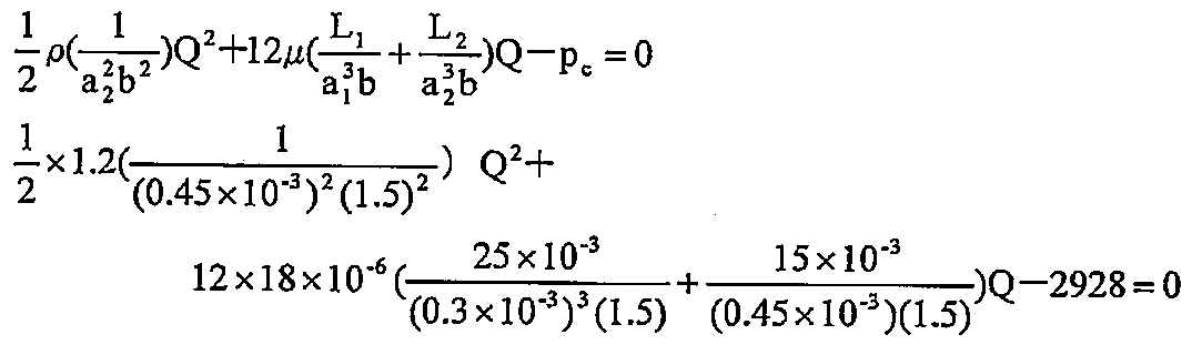
よって、第1の流路のレイノルズ数Re1、第2の流路のレイノルズ数Re2は、
 また式(b)、(c)では、Δp1=2185(Pa)、Δp2=388(Pa)となり、第1の流路の圧力損失が上昇して第2の流路入口の静圧p2inは、p2in=p2in-p0=Δp2=388(Pa)となる。
さらに、第2の流路が拡大したときの曲率半径r+a2、引取張力Tとバランスする必要静圧力分p2inを確認すると、p2in=T/(r+a2)=5/((5+0.45)×10-3)=917(Pa)となり、第2の流路の圧力低下分よりも高く、拡大した流路断面幅が狭くなる方向へ戻る自己復元力を持つことが分かる。仮にこの値が第2の流路での静圧よりも低くなると、流路断面幅は広がる方向へ大きくなリ、自己復元力は無くなる。
つまり、上記する(d)式の第2の流路の流路断面幅が広くなった場合、溶融樹脂の曲率半径は大きくなって少ない静圧で引取張力とバランスすることになるが、実際には流路断面幅が広くなった際に第2の流路の静圧の減少分が溶融樹脂の曲率半径の増加による必要静圧の減少分より大きいために、溶融樹脂は第2の流路の流路断面幅が狭くなる方向へ戻ることが確認できた。このようにして、自己復元力が保持できるように、第1の流路および第2の流路の形状を決定すればよい。
次に、第2の流路の流路断面幅が50%狭くなったa2=0.15×10⁻³(m)の場合を同様に計算すると、流量Q及び流路の流速vは、Q=0.0036(m3/s)、v1=8.0(m/s)、v2=15.9(m/s)となり、レイノルズ数Reは、Re1=320 <2000、Re2=318 <2000となる。
圧力損失については、Δp1=479(Pa)、Δp2=2297(Pa)である。つまり、p2in=2297(Pa)となり、第1の流路の圧力損失が減少し、第2の流路入口での静圧が増加する。さらに、第2の流路が狭くなったときの曲率半径r+a2、引取張力Tとバランスする必要静圧力分p2inは、p2in=T/(r+a2)=5/((5+0.15)×10-3)=970(Pa)である。この値は実際のp2in=2297(Pa)よりも低いことが分かる。以上より、狭くなった第2の流路の流路断面幅が広がる方向へ自己復元力を持つことが確認できた。
また、第2の流路の長さL2のみを長くした場合を前記同様に計算すると、L2=50×10-3(m)のとき、チャンバー元圧pc=4500(Pa)(定常時のp2in=943(Pa)、Q=0.0118(m3/s)は同じ)となり、第2の流路の流路断面幅が50%広がったとき、曲り流路の入口圧p2in=345(Pa)、Q=0.0145(m3/s)となり、第2の流路の流路断面幅が50%狭くなったとき、第2の流路の入口圧p2in=2994(Pa)、Q=0.0047(m3/s)となり、L2=25×10-3(m)に比して圧力変化量が大きく、流量変化量は小さいことが分かる。
第1の流路で大気開放した場合、速度は0に近づき、第1の流路出口の速度(動圧)は静圧に変化する。このとき生じる静圧分は負圧になる。

この負圧分がダイ出口の溶融樹脂の経路に悪影響を及ぼす場合、長さL3、流体断面幅a3からなる第3の流路を追加することで、大気開放位置を溶融樹脂から離すことができる。第3の流路で動圧分を静圧分へ完全に変換する場合、L3=10×10-3[m]とすると、流体流路幅a3は以下のようになる。
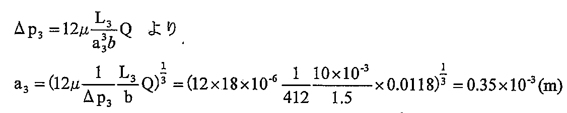
以上、本発明の実施の形態を図面を用いて詳述してきたが、具体的な構成はこの実施形態に限定されるものではなく、本発明の要旨を逸脱しない範囲における設計変更等があっても、それらは本発明に含まれるものである。
1…ダイ、1a…出口、1b…下端面、2…押出機、3A…プレロール、3B,3C…ラミネートロール、5、5A、5B,5C,5D,5E…流体チャンバー、5a…筒部の天板、5a1…第1の領域(対向面)、5a2…第2の領域(対向面)、5a2’…第2の領域の湾曲部、5a2”… 第2の領域の直線部(垂線)、5a2’’’…第2の領域の直線部(傾線)、5a3…上端面、5b…側面(側板)、5c…底板、5d…内部流路、5e…幅方向端部領域の流路、5f…別途の流路、5g…ローラー、6…コンプレッサ、7…流体提供部、8A…第1の加熱部、8B…第2の加熱部、9…第3の加熱部、10,10A,10B,10C,10E…製造装置、fd…流体、K…空間、S…隙間、p…流体圧、fl…溶融樹脂、FL…樹脂被膜、BP…基板
Claims (34)
- ダイの下端面に開設された出口から下方に押出された溶融樹脂を、金属製の基板とともに該出口の下方に位置して回転する一対のラミネートロール間で挟圧し、溶融樹脂を冷却および固化して基板の表面に樹脂被膜が被覆してなる樹脂被覆基板を製造する樹脂被覆基板の製造装置であって、
前記製造装置は、前記出口と前記ラミネートロールの間にプレロールを備え、該出口から押出された溶融樹脂が該プレロールに接地し、次いで一対のラミネートロール間に送られるようになっており、さらに、前記出口とその下方の該プレロールの間の空間に流体を提供する流体チャンバーを備えており、
前記流体チャンバーは前記空間および前記プレロールに対向する対向面を有しており、
前記流体チャンバーから提供された流体は、前記対向面に沿う流体流路をダイ側に流れながら、前記空間内に存在する溶融樹脂がプレロールの回転方向に変位して引取られようとするのを押し戻す方向に流体圧を付与させるようになっている樹脂被覆基板の製造装置。 - 前記ダイが2つあり、それぞれのダイの下方に前記プレロールがあって、それぞれのダイの出口から下方に押出された溶融樹脂が対応するプレロールに接地し、次いで双方の溶融樹脂が基板を挟んだ姿勢で一対のラミネートロール間で挟圧される請求項1に記載の樹脂被覆基板の製造装置。
- 前記流体チャンバーには、前記流体を加熱してその温度を調整し、加熱温調された流体を生成するための第1の加熱部が設けられている請求項1または2に記載の樹脂被覆基板の製造装置。
- 前記プレロールには、該プレロールを加熱温調するための第2の加熱部が設けられている請求項1または2に記載の樹脂被覆基板の製造装置。
- 前記プレロールと前記一対のラミネートロールの間であって、プレロールに接地して下方へ溶融樹脂が送られる搬送路に第3の加熱部が設けられている請求項1~4のいずれかに記載の樹脂被覆基板の製造装置。
- 前記対向面は、プレロールのロール面と相補的形状を呈する第1の領域と、該第1の領域からダイの前記出口側へ曲がって流体チャンバーの上端に至る第2の領域と、からなり、
前記流体流路は、前記第1の領域と前記ロール面上の溶融樹脂の間の第1の流路と、前記第2の領域と前記出口下方の空間内にある溶融樹脂の間の第2の流路とからなり、
第2流路に連続した第1の流路の流路断面幅が、流体チャンバーの内部流路に比して狭くなっている請求項1~5のいずれかに記載の樹脂被覆基板の製造装置。 - 流体チャンバーの前記上端面は平坦面を成し、
前記対向面の前記第2の領域の曲率半径は前記上端面との交点に向かって増加しており、
前記出口から押出された溶融樹脂は前記流体圧を受けながら、下方の前記空間に延びた後に前記第2の流路を介して前記第2の領域に沿うようにして前記ロール面に達し、前記第1の流路を介して前記第1の領域に沿うようにして該ロール面に密着する請求項6に記載の樹脂被覆基板の製造装置。 - 前記第2の領域が前記上端面に対して直交しており、
前記出口から押出された溶融樹脂は前記流体圧を受けながら、前記空間内を鉛直下方に延びた後に前記第2の流路を介して前記第2の領域に沿うようにして前記ロール面に達し、前記第1の流路を介して前記第1の領域に沿うようにして該ロール面に密着する請求項7に記載の樹脂被覆基板の製造装置。 - 前記第2の領域は、第1の領域からダイの前記出口側へ曲がる湾曲部と、該湾曲部に連続して前記上端面に対して直交する直線部を有している請求項8に記載の樹脂被覆基板の製造装置。
- 前記第2の領域は、第1の領域からダイの前記出口側へ曲がる湾曲部と、該湾曲部に連続して第2の流路の流路断面を大きくする方向であって前記出口から遠ざかる方向に傾斜して前記上端面に交差する直線部を有している請求項7に記載の樹脂被覆基板の製造装置。
- 前記出口が臨むダイの前記下端面と流体チャンバーの前記上端面はともに平坦面を成し、
流体チャンバーの前記上端面とダイの前記下端面の間には、前記対向面に沿う流体流路が延びてさらに第3の流路を形成しており、
第3の流路を流れた流体は、該第3の流路よりも流路断面の大きな下流方向に放出されるようになっている請求項1~10のいずれかに記載の樹脂被覆基板の製造装置。 - 前記第3の流路における流体圧が大気圧より大きくなるように該第3の流路の流路断面積が調整されている請求項11に記載の樹脂被覆基板の製造装置。
- 前記第1の流路の流路抵抗が前記第2の流路の流路抵抗の0.3倍以上である請求項6~12のいずれかに記載の樹脂被覆基板の製造装置。
- 流体チャンバーから少なくとも2種類の流体圧の流体が提供されるようになっており、流体チャンバーの幅方向端部領域から提供される流体の流体圧が、その内側領域から提供される流体の流体圧に比して相対的に高圧に調整されている請求項1~13のいずれかに記載の樹脂被覆基板の製造装置。
- 前記流体チャンバーはその内部流路と該内部流路周囲の筒部とから構成され、
前記内部流路が前記対向面に臨む開口に連通し、かつ、前記筒部の端面の一部が前記対向面の前記第2の領域となっており、
前記筒部の幅方向端部領域には、該筒部の前記端面の一部に臨む開口とこれに連通する別途の流路が形成されており、
流体チャンバーの前記内部流路から流体が提供されてこれが前記流体流路を流れ、かつ、前記別途の流路から前記流体流路にさらに流体が提供される請求項6~14のいずれかに記載の樹脂被覆基板の製造装置。 - 前記別途の流路から提供された流体の温度が、前記流体流路を流れる流体の温度に比して高温である請求項15に記載の樹脂被覆基板の製造装置。
- 前記流体チャンバーはその内部流路と該内部流路周囲の筒部とから構成され、
前記筒部の幅方向の2つの側面にローラーが取り付けられ、該ローラーが前記プレロールに回転自在に接触して少なくとも前記第1の流路の流路断面幅を保証する請求項6~16のいずれかに記載の樹脂被覆基板の製造装置。 - ダイの下端面に開設された出口から下方に押出された溶融樹脂を、金属製の基板とともに該出口の下方に位置して回転する一対のラミネートロール間で挟圧し、溶融樹脂を冷却および固化して基板の表面に樹脂被膜が被覆してなる樹脂被覆基板を製造する樹脂被覆基板の製造方法であって、
前記出口と前記ラミネートロールの間にプレロールがあり、該出口から押出された溶融樹脂を該プレロールに接地させ、次いで一対のラミネートロール間に溶融樹脂を送る過程において、流体チャンバーから、前記出口とその下方の前記プレロールの間の空間に流体を提供し、該流体チャンバーの有する前記空間および前記プレロールに対向する対向面に沿う流体流路を介してダイ側に前記流体を流し、前記空間内に存在する溶融樹脂がプレロールの回転方向に変位して引取られようとするのを押し戻す方向に流体圧を付与させながら、溶融樹脂をプレロールに接地させ、次いで溶融樹脂と基板をラミネートロールに挟圧させ、溶融樹脂を冷却および固化して基板の表面に樹脂被膜が被覆してなる樹脂被覆基板を製造する樹脂被覆基板の製造方法。 - 前記ダイが2つあり、それぞれのダイの下方に前記プレロールがあって、それぞれのダイの出口から下方に押出された溶融樹脂が対応するプレロールに接地し、次いで双方の溶融樹脂が基板を挟んだ姿勢で一対のラミネートロール間で挟圧される請求項18に記載の樹脂被覆基板の製造方法。
- 前記流体を加熱してその温度を調整し、加熱温調された流体を前記流体チャンバーから前記空間に提供する請求項18または19に記載の樹脂被覆基板の製造方法。
- 前記プレロールを加熱してその表面の温度を調整しておき、加熱温調されたプレロール表面に溶融樹脂を接地させる請求項18または19に記載の樹脂被覆基板の製造方法。
- 前記プレロールと前記一対のラミネートロールの間であって、プレロールに接地して下方へ送られる溶融樹脂を加熱し、加熱後の溶融樹脂を該一対のラミネートロールに送る請求項18~21のいずれかに記載の樹脂被覆基板の製造方法。
- 前記対向面は、プレロールのロール面と相補的形状を呈する第1の領域と、該第1の領域からダイの前記出口側へ曲がって流体チャンバーの上端に至る第2の領域と、からなり、
前記流体流路は、前記第1の領域と前記ロール面上の溶融樹脂の間の第1の流路と、前記第2の領域と前記出口下方の空間内にある溶融樹脂の間の第2の流路とからなり、
第2流路に連続した第1の流路の流路断面幅が、流体チャンバーの内部流路に比して狭くなっている請求項18~22のいずれかに記載の樹脂被覆基板の製造方法。 - 流体チャンバーの前記上端面は平坦面を成し、
前記対向面の前記第2の領域の曲率半径は前記上端面との交点に向かって増加しており、
前記出口から押出された溶融樹脂に前記流体圧を付与しながら、該溶融樹脂を、下方の前記空間に延ばした後に前記第2の流路を介して前記第2の領域に沿うようにして前記ロール面に到達せしめ、前記第1の流路を介して前記第1の領域に沿うようにして該ロール面に密着させる請求項23に記載の樹脂被覆基板の製造方法。 - 前記第2の領域が前記上端面に対して直交しており、
前記出口から押出された溶融樹脂に前記流体圧を付与しながら、該溶融樹脂を、前記空間内を鉛直下方に延ばした後に前記第2の流路を介して前記第2の領域に沿うようにして前記ロール面に到達せしめ、前記第1の流路を介して前記第1の領域に沿うようにして該ロール面に密着させる請求項24に記載の樹脂被覆基板の製造方法。 - 前記第2の領域は、第1の領域からダイの前記出口側へ曲がる湾曲部と、該湾曲部に連続して前記上端面に対して直交する直線部を有している請求項25に記載の樹脂被覆基板の製造方法。
- 前記第2の領域は、第1の領域からダイの前記出口側へ曲がる湾曲部と、該湾曲部に連続して第2の流路の流路断面を大きくする方向であって前記出口から遠ざかる方向に傾斜して前記上端面に交差する直線部を有している18~22のいずれかに記載の樹脂被覆基板の製造方法。
- 前記出口が臨むダイの前記下端面と流体チャンバーの前記上端面はともに平坦面を成し、
流体チャンバーの前記上端面とダイの前記下端面の間には、前記対向面に沿う流体流路が延びてさらに第3の流路を形成しており、
第2の流路に次いで第3の流路に流体を流し、該第3の流路よりも流路断面の大きな下流方向に流体を放出する請求項23~27のいずれかに記載の樹脂被覆基板の製造方法。 - 前記第3の流路における流体圧が大気圧より大きくなるように該第3の流路の流路断面積を調整する請求項28に記載の樹脂被覆基板の製造方法。
- 前記第1の流路の流路抵抗を前記第2の流路の流路抵抗の0.3倍以上に調整する請求項23~29のいずれかに記載の樹脂被覆基板の製造方法。
- 流体チャンバーから少なくとも2種類の流体圧の流体が提供されるようになっており、流体チャンバーの幅方向端部領域から提供される流体の流体圧を、その内側領域から提供される流体の流体圧に比して相対的に高圧となるように調整する請求項18~30のいずれかに記載の樹脂被覆基板の製造方法。
- 前記流体チャンバーはその内部流路と該内部流路周囲の筒部とから構成され、
前記内部流路が対向面に臨む開口に連通し、かつ、前記筒部の端面の一部が前記対向面の前記第2の領域となっており、
前記筒部の幅方向端部領域には、該筒部の前記端面の一部に臨む開口とこれに連通する別途の流路が形成されており、
流体チャンバーの前記内部流路から流体を提供して前記流体流路に流し、かつ、前記別途の流路から前記流体流路にさらに流体を提供する請求項23~31のいずれかに記載の樹脂被覆基板の製造方法。 - 前記別途の流路から提供する流体の温度を、前記流体流路を流れる流体の温度に比して高温にしておく請求項32に記載の樹脂被覆基板の製造方法。
- 前記流体チャンバーはその内部流路と該内部流路周囲の筒部とから構成され、
前記筒部の幅方向の2つの側面にローラーが取り付けられ、該ローラーが前記プレロールに回転自在に接触して少なくとも前記第1の流路の流路断面幅を保証する請求項23~33のいずれかに記載の樹脂被覆基板の製造方法。
Applications Claiming Priority (2)
| Application Number | Priority Date | Filing Date | Title |
|---|---|---|---|
| JP2011042134A JP5666345B2 (ja) | 2011-02-28 | 2011-02-28 | 樹脂被覆基板の製造装置および製造方法 |
| JP2011-042134 | 2011-02-28 |
Publications (1)
| Publication Number | Publication Date |
|---|---|
| WO2012117921A1 true WO2012117921A1 (ja) | 2012-09-07 |
Family
ID=46757858
Family Applications (1)
| Application Number | Title | Priority Date | Filing Date |
|---|---|---|---|
| PCT/JP2012/054342 Ceased WO2012117921A1 (ja) | 2011-02-28 | 2012-02-23 | 樹脂被覆基板の製造装置および製造方法 |
Country Status (2)
| Country | Link |
|---|---|
| JP (1) | JP5666345B2 (ja) |
| WO (1) | WO2012117921A1 (ja) |
Families Citing this family (2)
| Publication number | Priority date | Publication date | Assignee | Title |
|---|---|---|---|---|
| JP5620854B2 (ja) * | 2011-02-28 | 2014-11-05 | 東洋鋼鈑株式会社 | フィルム製造装置および製造方法 |
| TWI640554B (zh) * | 2016-11-28 | 2018-11-11 | 林紫綺 | 均溫擠壓成型系統及其均溫滾輪結構 |
Citations (3)
| Publication number | Priority date | Publication date | Assignee | Title |
|---|---|---|---|---|
| JP2001121647A (ja) * | 1999-10-29 | 2001-05-08 | Toyo Seikan Kaisha Ltd | 押出ラミネート材の製造方法 |
| JP2001170991A (ja) * | 1999-12-21 | 2001-06-26 | Sumitomo Bakelite Co Ltd | 高分子シートの製造装置、製造方法およびこれを用いた高分子シート |
| WO2007148641A1 (ja) * | 2006-06-20 | 2007-12-27 | Toyo Kohan Co., Ltd. | 有機樹脂被覆金属板の製造方法およびその製造装置 |
Family Cites Families (1)
| Publication number | Priority date | Publication date | Assignee | Title |
|---|---|---|---|---|
| JPH06285953A (ja) * | 1993-04-05 | 1994-10-11 | Mitsubishi Heavy Ind Ltd | フィルム等の成形装置 |
-
2011
- 2011-02-28 JP JP2011042134A patent/JP5666345B2/ja active Active
-
2012
- 2012-02-23 WO PCT/JP2012/054342 patent/WO2012117921A1/ja not_active Ceased
Patent Citations (3)
| Publication number | Priority date | Publication date | Assignee | Title |
|---|---|---|---|---|
| JP2001121647A (ja) * | 1999-10-29 | 2001-05-08 | Toyo Seikan Kaisha Ltd | 押出ラミネート材の製造方法 |
| JP2001170991A (ja) * | 1999-12-21 | 2001-06-26 | Sumitomo Bakelite Co Ltd | 高分子シートの製造装置、製造方法およびこれを用いた高分子シート |
| WO2007148641A1 (ja) * | 2006-06-20 | 2007-12-27 | Toyo Kohan Co., Ltd. | 有機樹脂被覆金属板の製造方法およびその製造装置 |
Also Published As
| Publication number | Publication date |
|---|---|
| JP5666345B2 (ja) | 2015-02-12 |
| JP2012179722A (ja) | 2012-09-20 |
Similar Documents
| Publication | Publication Date | Title |
|---|---|---|
| JP2002096370A (ja) | 口金、シートならびにその製造装置および製造方法 | |
| CN102892567B (zh) | 膜制造装置及制造方法 | |
| Kostic et al. | Design of extrusion dies | |
| JPH0453693B2 (ja) | ||
| JP5528980B2 (ja) | フィルム製造装置および製造方法 | |
| JP2016153230A (ja) | 押出ダイのランドチャネル長さを調整するシステム及び方法 | |
| JP5666345B2 (ja) | 樹脂被覆基板の製造装置および製造方法 | |
| EP2961701B1 (en) | Apparatus and method for forming a glass sheet with core glass and clad glass | |
| JP5620854B2 (ja) | フィルム製造装置および製造方法 | |
| US20140265059A1 (en) | Apparatus for manufacturing and processing films having strips of increased thickness | |
| JP6298419B2 (ja) | ダイ、溶液製膜方法及び溶融製膜方法 | |
| JP2020146853A (ja) | 押出成形用ダイおよび押出成形装置 | |
| JP2000006227A (ja) | 押出成形用ダイ | |
| JP6921983B2 (ja) | 連続鋳造装置および方法 | |
| CN106626189B (zh) | 一种基于风压的聚酰胺酸树脂溶液贴附唇壁挤出流涎方法 | |
| CN204505791U (zh) | 均冷辊柔性压延薄膜制备装置 | |
| CN107030948A (zh) | 基于模头角度的聚酰胺酸树脂溶液贴附唇壁挤出流涎方法 | |
| JP3981881B2 (ja) | 熱可塑性エラストマーシートの製造方法 | |
| JP2013103367A (ja) | ダイアダプタ及びシート押出成形装置 | |
| CN100396470C (zh) | 管状热塑性薄膜的纵向定向 | |
| JP7603501B2 (ja) | 板状樹脂成形体の製造方法 | |
| CN116600966B (zh) | 用于挤出流体材料的设备 | |
| JP3753406B2 (ja) | 樹脂被覆金属板の製造装置および製造方法 | |
| CN108044857A (zh) | 压延装置 | |
| JP2018161755A (ja) | シート・フィルム成形ロール装置、シート・フィルム製造装置、およびシート・フィルム製造方法 |
Legal Events
| Date | Code | Title | Description |
|---|---|---|---|
| 121 | Ep: the epo has been informed by wipo that ep was designated in this application |
Ref document number: 12752439 Country of ref document: EP Kind code of ref document: A1 |
|
| NENP | Non-entry into the national phase |
Ref country code: DE |
|
| WWE | Wipo information: entry into national phase |
Ref document number: 1301004744 Country of ref document: TH |
|
| 122 | Ep: pct application non-entry in european phase |
Ref document number: 12752439 Country of ref document: EP Kind code of ref document: A1 |