WO2012117528A1 - 状態推定装置 - Google Patents
状態推定装置 Download PDFInfo
- Publication number
- WO2012117528A1 WO2012117528A1 PCT/JP2011/054651 JP2011054651W WO2012117528A1 WO 2012117528 A1 WO2012117528 A1 WO 2012117528A1 JP 2011054651 W JP2011054651 W JP 2011054651W WO 2012117528 A1 WO2012117528 A1 WO 2012117528A1
- Authority
- WO
- WIPO (PCT)
- Prior art keywords
- state estimation
- observation
- model
- state
- target
- Prior art date
- Legal status (The legal status is an assumption and is not a legal conclusion. Google has not performed a legal analysis and makes no representation as to the accuracy of the status listed.)
- Ceased
Links
Images









Classifications
-
- G—PHYSICS
- G06—COMPUTING OR CALCULATING; COUNTING
- G06F—ELECTRIC DIGITAL DATA PROCESSING
- G06F17/00—Digital computing or data processing equipment or methods, specially adapted for specific functions
- G06F17/10—Complex mathematical operations
- G06F17/18—Complex mathematical operations for evaluating statistical data, e.g. average values, frequency distributions, probability functions, regression analysis
-
- G—PHYSICS
- G01—MEASURING; TESTING
- G01S—RADIO DIRECTION-FINDING; RADIO NAVIGATION; DETERMINING DISTANCE OR VELOCITY BY USE OF RADIO WAVES; LOCATING OR PRESENCE-DETECTING BY USE OF THE REFLECTION OR RERADIATION OF RADIO WAVES; ANALOGOUS ARRANGEMENTS USING OTHER WAVES
- G01S17/00—Systems using the reflection or reradiation of electromagnetic waves other than radio waves, e.g. lidar systems
- G01S17/66—Tracking systems using electromagnetic waves other than radio waves
-
- G—PHYSICS
- G01—MEASURING; TESTING
- G01S—RADIO DIRECTION-FINDING; RADIO NAVIGATION; DETERMINING DISTANCE OR VELOCITY BY USE OF RADIO WAVES; LOCATING OR PRESENCE-DETECTING BY USE OF THE REFLECTION OR RERADIATION OF RADIO WAVES; ANALOGOUS ARRANGEMENTS USING OTHER WAVES
- G01S17/00—Systems using the reflection or reradiation of electromagnetic waves other than radio waves, e.g. lidar systems
- G01S17/88—Lidar systems specially adapted for specific applications
- G01S17/93—Lidar systems specially adapted for specific applications for anti-collision purposes
- G01S17/931—Lidar systems specially adapted for specific applications for anti-collision purposes of land vehicles
-
- G—PHYSICS
- G08—SIGNALLING
- G08G—TRAFFIC CONTROL SYSTEMS
- G08G1/00—Traffic control systems for road vehicles
- G08G1/16—Anti-collision systems
-
- G—PHYSICS
- G08—SIGNALLING
- G08G—TRAFFIC CONTROL SYSTEMS
- G08G1/00—Traffic control systems for road vehicles
- G08G1/16—Anti-collision systems
- G08G1/165—Anti-collision systems for passive traffic, e.g. including static obstacles, trees
-
- G—PHYSICS
- G08—SIGNALLING
- G08G—TRAFFIC CONTROL SYSTEMS
- G08G1/00—Traffic control systems for road vehicles
- G08G1/16—Anti-collision systems
- G08G1/166—Anti-collision systems for active traffic, e.g. moving vehicles, pedestrians, bikes
Definitions
- the present invention relates to an estimation apparatus that estimates a state of an observation target by applying measurement data to a state estimation model.
- an apparatus described in Japanese Patent Application Laid-Open No. 2002-259966 is known as a technique for estimating the state of a dynamic observation target.
- the apparatus described in Japanese Patent Application Laid-Open No. 2002-259966 is provided with a plurality of recognition means, and increases the accuracy of estimation by switching the recognition method according to a predetermined condition.
- a state estimation method using a filter such as a Kalman filter
- state estimation models such as an observation model, an observation noise model, a motion model, and a motion noise model are set.
- the Kalman filter estimates the dynamic observation target state with high accuracy by applying the measurement data of the observation target to the set state estimation model.
- the state estimation model is fixed even though the state of the observation target changes every moment, so the state of the observation target is always estimated with high accuracy. There is a problem that can not be.
- an object of the present invention is to provide a state estimation device that can estimate the state of an observation target with higher accuracy.
- a state estimation device is a state estimation device that estimates the state of an observation target by applying measurement data measured by a measurement device that measures the observation target to a state estimation model, and the positional relationship with the observation target or It has a change means which changes the model for state estimation based on the state of observation object.
- the state estimation device since the state estimation model is changed based on the positional relationship with the observation target or the state of the observation target, the state of the dynamic observation target can be estimated with higher accuracy. it can.
- the observation target is a vehicle existing around the measurement apparatus
- the changing unit changes the state estimation model based on the direction of the center position of the observation target with respect to the measurement apparatus. If the direction of the center position of the observation target with respect to the measurement device is different, the measurable plane of the observation target is different. For this reason, if the same state estimation model is used regardless of the direction of the center position of the observation target with respect to the measurement apparatus, it is not possible to appropriately associate the measurement data with the state estimation model. As a result, the state of the observation target cannot be estimated with high accuracy. Therefore, by changing the state estimation model based on the direction of the center position of the observation target with respect to the measurement apparatus, the measurement data and the state estimation model can be associated with each other appropriately. Thereby, the estimation accuracy of the state of the observation target can be further improved.
- the observation target is a vehicle existing around the measurement apparatus, and the changing means changes the state estimation model based on the direction of the observation target. If the direction of the observation target is different, the measurable surface of the observation target is different. For this reason, if the same state estimation model is used regardless of the orientation of the observation target, it is not possible to properly associate the measurement data with the state estimation model. As a result, the state of the observation target cannot be estimated with high accuracy. Therefore, by changing the state estimation model based on the direction of the observation target, it is possible to appropriately associate the measurement data with the state estimation model, so that it is possible to further improve the estimation accuracy of the state of the observation target. .
- the observation target is a vehicle existing around the measurement device
- the changing means generates a state estimation model based on both the direction of the central position of the observation target with respect to the measurement device and the direction of the observation target. It is preferable to change.
- the surface facing the host vehicle to be observed can be specified by both the direction of the center position of the observation target with respect to the measuring device and the direction of the observation target. For this reason, by changing the state estimation model based on both of these pieces of information, the measurement data and the state estimation model can be appropriately associated with each other, so that the estimation accuracy of the state to be observed can be further improved. it can.
- the changing means preferably narrows down the state estimation model to which the measurement data is applied based on the state estimation model used in the previous estimation. Since the behavior change of the observation target is usually continuous, the selection of the wrong state estimation model is reduced by narrowing down the state estimation model based on the state estimation model used in the previous estimation. can do.
- the changing unit estimates the direction of the center position of the observation target with respect to the measuring apparatus or the direction of the observation target based on the state of the observation target estimated last time.
- the estimation continuity is maintained by using the previously estimated information, the estimation accuracy of the state of the observation target can be further improved.
- the changing means estimates the direction of the observation target based on the map information of the position where the observation target exists.
- the orientation of the observation target cannot be obtained from the measurement data. Therefore, by using the map information of the position where the observation target exists, the direction of the observation target can be estimated even in such a case.
- the changing means generates a model to be observed from the measurement data and changes the state estimation model based on the number of sides constituting the model. In this way, by changing the state estimation model based on the number of model edges generated from the measurement data, the change criterion for the state estimation model is clarified. Further improvement can be achieved.
- the state estimation model includes an observation noise model in which the observation noise generated by the measurement of the measurement device is represented by a variance value, and the changing unit changes the variance value of the observation noise model based on the orientation with respect to the surface to be observed. It is preferable.
- the observation noise of the measurement data is small in the direction perpendicular to the surface of the observation target, and the observation noise of the measurement data is large in the direction horizontal to the surface of the observation target. Therefore, the estimation accuracy of the state of the observation target can be further improved by changing the variance value of the observation noise model based on the orientation with respect to the surface of the measurement target.
- the changing means changes the observation noise model based on the distance to the observation target.
- the observation noise becomes small because the measurement target area of the observation target is large.
- the observation noise becomes large because the measurement target area of the observation target is small. Therefore, by changing the observation noise model according to the distance to the measurement target, it is possible to further improve the estimation accuracy of the state of the observation target.
- the observation target is a vehicle that exists in the vicinity of the measuring device, and the state estimation model includes a motion model that represents the motion state of the surrounding vehicle and a motion noise model that represents the amount of change in the steering angle in the motion model.
- the changing unit reduces the amount of change in the steering angle in the motion noise model when the speed of the observation target is high compared to when the speed of the observation target is low.
- the speed of the observation target is high, the possibility of turning the steering wheel large is low. Therefore, if the speed of the observation target is high, the estimation accuracy of the state of the observation target can be further improved by reducing the amount of change in the steering angle in the motion noise model.
- the state of the observation target can be estimated with high accuracy.
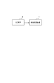
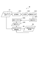
- FIG. 1 is a block diagram showing a state estimation apparatus according to this embodiment.
- the state estimation apparatus 1 according to the present embodiment is mounted on a vehicle and is electrically connected to a LIDAR (Light Detection and Ranging) 2.
- LIDAR Light Detection and Ranging
- LIDAR 2 is a radar that measures another vehicle using laser light, and functions as a measuring device.
- the LIDAR 2 emits laser light and receives reflected light of the emitted laser light to detect a point sequence of reflection points. Then, LIDAR 2 calculates measurement data of the detected point sequence from the speed of the laser light, the emission time of the laser light, and the reception time of the reflected light.
- the measurement data includes, for example, a relative distance from the own vehicle, a relative direction with respect to the own vehicle, coordinates calculated from the relative distance to the own vehicle and the relative direction with respect to the own vehicle, and the like. Then, the LIDAR 2 transmits the detected measurement data of the point sequence to the state estimation device 1.
- the state estimation device 1 estimates the state of other vehicles existing around the host vehicle by an estimation process using a Kalman filter.
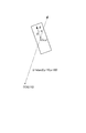
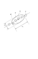
- FIG. 2 is a diagram showing variables to be estimated.
- variables to be estimated are, for example, center position (x), center position (y), speed (v), direction ( ⁇ ), tire angle ( ⁇ ), wheel base (b), length (L) and width (w).
- the state estimation apparatus 1 estimates each said variable by calculating by applying the measurement data transmitted from LIDAR2 to a predetermined model for state estimation, and outputs this estimated variable as a state estimated value of the target vehicle. To do.
- the process for estimating the variable in this way is referred to as a Kalman filter update process.
- the state estimation device 1 changes the state estimation model used for the Kalman filter update process based on the positional relationship with the target vehicle and the state of the target vehicle. For this reason, the state estimation apparatus 1 also functions as a changing unit that changes the state estimation model.
- the state estimation model used for the Kalman filter update processing is represented by an observation model, an observation noise model, a motion model, and a motion noise model, as will be described later.
- the Kalman filter estimates the observation target state (state vector) x k when only the observation amount (observation vector) z k is observed. For this reason, x k is a variable to be obtained by estimation.
- the measurement data measured by LIDAR 2 corresponds to the observation amount.
- the observation amount z k at time k is represented by an observation model shown in the following equation (1).
- v k is an observation noise model representing the observation noise entering the observation model.
- the observation noise is an error caused by observation, for example, an error caused by the characteristics of LIDAR2 or a reading error of LIDAR2.
- This observation noise model v k is expressed by the following equation (2) or (3) according to a normal distribution with an average 0 variance R.
- the state x k at time k is represented by the motion model shown in the following equation (4).
- u k is an operation amount.
- W k is a motion noise model representing motion noise entering the motion model.
- the motion noise is an error generated when a motion state different from the motion state assumed by the motion model is performed.
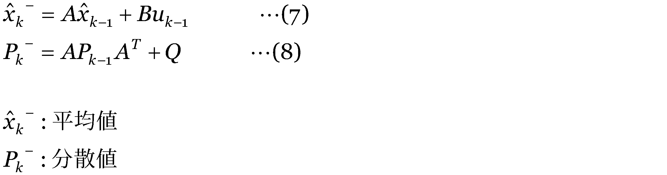
- the motion noise model w k is expressed by the following equation (5) or (6) according to a normal distribution with an average 0 variance Q.
- z 1 ,..., Z k ) is assumed to be a Gaussian distribution, and the probability p (x k + 1
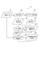
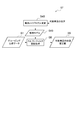
- FIG. 3 is a diagram illustrating an estimation process of the state estimation device according to the first embodiment.
- the state estimation device 11 changes the observation model used for the Kalman filter update process based on the direction of the center position of the target vehicle with respect to LIDAR 2 and the direction of the target vehicle.
- the observation model includes a rear observation model for the rear of the target vehicle, a left oblique rear observation model for the rear and left sides of the target vehicle, a left side observation model for the left side of the target vehicle, the front of the target vehicle, and Left diagonal front observation model for the left side, front side observation model for the front side of the target vehicle, right front side observation model for the front and right sides of the target vehicle, right side observation model for the right side of the target vehicle.
- the state estimation device 11 generates grouping point cloud data from the measurement data of the point sequence transmitted from the LIDAR 2 (S1). More specifically, when the LIDAR 2 detects a point sequence of reflection points, the state estimation device 11 generates grouping point group data obtained by grouping point sequences within a predetermined distance. Since this grouping point group data is generated corresponding to each vehicle, a plurality of grouping point group data is generated when there are a plurality of vehicles around the host vehicle.
- the state estimation device 11 obtains the position of the center of gravity of the grouping point cloud data generated in S1 (S2).
- the position of the center of gravity of the grouping point cloud data corresponds to the center position of the target vehicle.
- the barycentric position of the grouping point group data can be obtained, for example, by generating a vehicle model from the grouping point group data and calculating the barycentric position of the model.
- the state estimation device 11 calculates the azimuth angle of the center of gravity obtained in S2 viewed from the LIDAR 2 (S3). That is, the state estimation device 11 calculates the direction of the center of gravity position of the target vehicle with respect to LIDAR 2 in S3.
- the state estimation device 11 tracks the center-of-gravity position obtained in S2 for the past plural times, and estimates the speed of the center-of-gravity position obtained in S2 (S4). And the state estimation apparatus 11 calculates the speed direction of the gravity center position calculated
- the state estimation device 11 selects an observation model from the difference between the azimuth angle of the gravity center position calculated in S3 and the velocity direction of the gravity center position calculated in S5 (S6).
- FIG. 4 is a diagram illustrating the azimuth angle of the gravity center position and the velocity direction of the gravity center position.
- FIG. 5 is a diagram illustrating an example of reference for changing an observation model.
- O (X0, Y0) indicates the origin of LIDAR2
- C (x, y) indicates the position of the center of gravity obtained in S2.
- ⁇ represents the speed direction of the center of gravity C calculated in S5
- ⁇ represents the direction of the center of gravity C relative to the origin O and the direction calculated in S3.
- the state estimation device 11 selects the rear surface observation model.
- the state estimation device 11 selects the left oblique rear surface observation model.
- the state estimation device 11 selects the left side observation model.
- the state estimation device 11 selects the left oblique front observation model.
- the state estimation device 11 selects the front observation model.
- the state estimation device 11 selects the right oblique front observation model.
- the state estimation device 11 selects the right side observation model.
- the state estimation device 11 selects the right oblique rear surface observation model.
- the state estimation device 11 selects the rear surface observation model.
- FIG. 6 is a diagram for explaining a right oblique rear surface observation model.
- FIG. 7 is a diagram for explaining the rear surface observation model.
- the grouping point cloud data is constituted by a right grouping constituted by a point sequence arranged on the right side and a point sequence arranged on the left side. Grouped into left grouping. Since the grouping point group data is composed of a point sequence of reflection points, straight lines applied to the grouping point group data correspond to the front surface, rear surface, right surface, and left surface of the target vehicle.
- the variables to be estimated are the center position (x), the center position (y), the speed (v), the direction ( ⁇ ), the tire angle ( ⁇ ), the wheel base (b), and the length (l). , Width (w) (see FIG. 2).
- the variables in the right oblique back observation model are Right grouping center position (X R ) Center position of right grouping (Y R ) Long axis length in right grouping (L R ) Long axis orientation ( ⁇ R ) in right grouping
- the variables to be estimated are the center position (x), the center position (y), the speed (v), the direction ( ⁇ ), the tire angle ( ⁇ ), the wheel base (b), and the length (l). , Width (w) (see FIG. 2).
- the variables in the observation model for the right oblique rear surface are Grouping center position (X) Grouping center position (Y) Long axis length in grouping (L) Long axis orientation ( ⁇ ) in grouping It becomes.
- the state estimation apparatus 11 determines the observation model selected by S6 as an observation model used for this estimation (S7).
- the state estimation apparatus 11 performs Kalman filter update processing using the grouping point cloud data generated in S1 and the observation model determined in S7 (S8).
- the state estimation device 11 includes a center position (x), a center position (y), a speed (v), a direction ( ⁇ ), a tire angle ( ⁇ ), a wheel base (b), a length (l), A variable of width (w) is estimated, and the variance of each estimated variable (hereinafter referred to as “estimated variance value”) is calculated.
- the estimated variance value corresponds to the variance value P k expressed by the above equation (9).
- the state estimation apparatus 11 outputs the variable calculated by the Kalman filter update process of S8 as a state estimated value of the target vehicle (S9).
- the state estimation model is changed based on the positional relationship with the target vehicle and the state of the target vehicle.
- the accuracy can be estimated.
- the second embodiment is basically the same as the first embodiment, although the observation model selection method is different from the first embodiment. For this reason, below, only the part which is different from 1st Embodiment is demonstrated, and description of the part similar to 1st Embodiment is abbreviate
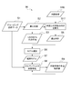
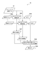
- FIG. 8 is a diagram illustrating an estimation process of the state estimation device according to the second embodiment. As shown in FIG. 8, the state estimation device 12 according to the second embodiment narrows down the observation model used in the current estimation process based on the observation model used in the previous estimation process.
- the surface of the vehicle seen from LIDAR2 is the rear surface, the left oblique rear surface, the left surface, the left oblique front surface, the front surface It changes only in the order of the right oblique front, the right face, the right oblique rear face, or the reverse order.
- the state estimation device 12 narrows down the observation model selected in S6 of the current estimation process based on the observation model determined in S7 of the previous estimation process (S11).
- the state estimation device 12 first identifies the observation model determined in S7 of the previous estimation process. Furthermore, the state estimation device 12 specifies two observation models that are adjacent to the observation model in the above order or the reverse order. And the state estimation apparatus 12 narrows down the observation model selected by S6 of this estimation process to these specified three observation models. For example, if the observation model determined in S7 of the previous estimation process is the rear observation model, the three observation models of the rear observation model, the right oblique rear face model, and the left oblique rear face model are used, and in this estimation process S6. Narrow down the observation model to select.
- the state estimation device 12 selects the observation model selected from the difference between the azimuth angle of the gravity center position calculated in S3 and the velocity direction of the gravity center position calculated in S5 as the observation model narrowed down in S11. The process continues in the same manner as in the first embodiment.
- the state estimation device 12 changes the observation model selected in S6 to the observation model determined in S7 of the previous estimation process, or the state estimation value of the observation target output by the current estimation process is reliable. Are treated as missing.
- an incorrect observation model is selected to narrow down the observation model used for the current estimation process based on the observation model used in the previous estimation process. Can be reduced.
- the third embodiment is basically the same as the first embodiment, although the observation model selection method is different from the first embodiment. For this reason, below, only the part which is different from 1st Embodiment is demonstrated, and description of the part similar to 1st Embodiment is abbreviate
- FIG. 9 is a diagram illustrating an estimation process of the state estimation device according to the third embodiment.
- the direction of the center position of the target vehicle with respect to LIDAR 2 and the direction of the target vehicle are obtained based on the grouping point cloud data generated in S1.
- the direction of the center position of the target vehicle with respect to LIDAR 2 and the direction of the target vehicle are set to the state estimated value of the target vehicle output in the previous estimation process. Ask based.
- the state estimation device 13 extracts the position (x, y) of the target vehicle from the estimated state value of the target vehicle output in S9 of the previous estimation process, and the LIDAR2 is extracted from the extracted position of the target vehicle.
- the direction of the center position of the target vehicle is calculated (S13).
- the state estimation device 13 extracts the speed direction ( ⁇ ) of the target vehicle from the state estimated value of the target vehicle output in S9 of the previous estimation process (S14).
- the state estimation device 13 selects an observation model from the difference between the direction of the center position of the target vehicle with respect to LIDAR 2 calculated in S13 and the speed direction of the target vehicle extracted in S14 (S6).
- the continuity of the estimation is maintained by using the state estimation value of the target vehicle output in the previous estimation process.
- the estimation accuracy of the state can be further improved.
- the fourth embodiment is basically the same as the first embodiment, although the observation model selection method is different from the first embodiment. For this reason, below, only the part which is different from 1st Embodiment is demonstrated, and description of the part similar to 1st Embodiment is abbreviate
- FIG. 10 is a diagram illustrating an estimation process of the state estimation device according to the fourth embodiment.
- the direction of the target vehicle is obtained based on the grouping point cloud data generated in S1.
- the direction of the target vehicle is obtained based on the map information.
- the state estimation device 14 first acquires map information (S16).
- This map information may be stored in a storage device mounted on the vehicle, such as a navigation system, or may be acquired from outside the vehicle by road-to-vehicle communication or the like.
- the state estimation device 14 specifies the position where the target vehicle exists in the map information by superimposing the center of gravity calculated in S2 on the map information acquired in S16. Then, the state estimation device 14 calculates the direction of the road on the map at the specified position, and estimates that the calculated road direction on the map is the speed direction of the target vehicle (S17).
- the position of the center of gravity of the grouping point group data is calculated in S2
- the position of the target vehicle is estimated from the grouping point group data, and the estimated position of the target vehicle is determined in S17. Based on this, the position of the target vehicle on the map may be specified.
- the direction of the target vehicle is estimated based on the position where the target vehicle exists, for example, when the target vehicle is stationary or the target vehicle Even if it is the case immediately after detecting this, the direction of the target vehicle can be estimated.
- the fifth embodiment is basically the same as the first embodiment, although the observation model selection method is different from the first embodiment. For this reason, below, only the part which is different from 1st Embodiment is demonstrated, and description of the part similar to 1st Embodiment is abbreviate
- FIG. 11 is a diagram illustrating an estimation process of the state estimation device according to the fifth embodiment
- FIG. 12 is a diagram illustrating the model selection process of FIG.
- the observation model is selected based on the direction of the center position of the target vehicle with respect to LIDAR2 calculated from the grouping point cloud data and the direction of the target vehicle.
- an observation model is selected based on the number of sides calculated from grouping point cloud data.
- the state estimation device 15 first calculates the convex hull of the grouping point cloud data generated in S1 (S21). In this convex hull calculation, first, the right end point and the left end point are specified from the grouping point cloud data. Then, the points of the grouping point group data are sequentially connected from the right end (or left side) point toward the left side (or right side), and when the left end (or right side) point is reached, the point connection ends. Since the grouping point cloud data is composed of a point sequence of reflection points, the lines connected by the convex hull calculation are one or two straight lines corresponding to the side surface of the target vehicle.
- the state estimation device 15 divides the sides of the convex hull calculated in S21 (S22).
- the line connected in the convex hull calculation of S21 becomes one or two straight lines corresponding to the side surface of the target vehicle. . For this reason, by dividing the sides of the convex hull in S21, it is possible to determine how many planes of the target vehicle are visible from LIDAR2.
- the state estimation device 15 determines whether or not the number of sides is 1 (S23).
- S23: YES determines whether the number of sides is 1 (S23: YES)
- S24 determines whether the length of the sides is shorter than a predetermined threshold (S24), and the number of sides is 1. If it is determined that it is not (S23: NO), it is determined whether or not the left side is longer than the right side (S31).
- the threshold value in S24 is a value for distinguishing the front and rear surfaces of the vehicle from the left and right surfaces. For this reason, the threshold value of S24 is a value between the width of the front and rear surfaces and the length of the left and right surfaces of a general vehicle.
- the state estimation device 15 that has proceeded to S24 determines that the length of the side is shorter than the predetermined threshold (S24: YES), whether or not the speed direction of the target vehicle is away from the host vehicle. If it is determined that the side length is not shorter than the predetermined threshold (S24: NO), it is determined whether or not the speed direction of the target vehicle is rightward when viewed from the own vehicle (S28). ).
- the speed direction of the target vehicle can be detected by various methods. For example, it may be obtained by tracking the position of the center of gravity of the grouping point cloud data as in the first embodiment, and from the state estimation value output in the previous estimation process as in the third embodiment. You may ask for it.
- the state estimation device 15 that has proceeded to S25 determines that the speed direction of the target vehicle is away from the host vehicle (S25: YES), it selects the rear-surface observation model (S26), and the speed of the target vehicle. If it is determined that the direction is not the direction away from the host vehicle (S25: NO), the front model is selected (S27).
- the state estimation device 15 that has proceeded to S28 determines that the speed direction of the target vehicle is rightward as viewed from the host vehicle (S28: YES), the right side observation model is selected (S29), and the speed direction of the target vehicle is If it is determined that the vehicle is not facing right as viewed from the vehicle (S28: NO), the left surface observation model is selected.
- the state estimation device 15 that has proceeded to S31 determines that the left side is longer than the right side in the determination of S31 described above (S31: YES), is the speed direction of the target vehicle away from the host vehicle? If it is determined (S32) and it is determined that the left side is not longer than the right side (S31: NO), it is determined whether the speed direction of the target vehicle is away from the host vehicle (S35). ).
- the state estimation device 15 that has proceeded to S32 determines that the speed direction of the target vehicle is away from the host vehicle (S32: YES), it selects the left oblique rear surface observation model (S33), and the target vehicle If it is determined that the speed direction is not the direction away from the host vehicle (S32: NO), the right oblique front model is selected (S34).
- the state estimation device 15 that has proceeded to S35 determines that the speed direction of the target vehicle is away from the host vehicle (S35: YES), it selects the right oblique rear surface observation model (S36), and the target vehicle. If it is determined that the speed direction is a direction away from the host vehicle (S35: NO), a left oblique rear surface observation model is selected (S37).
- S35 it may be determined whether the speed direction of the target vehicle is rightward as viewed from the host vehicle.
- the state estimation device 15 determines that the speed direction of the target vehicle is rightward when viewed from the host vehicle, the state estimation device 15 selects a right oblique rear surface observation model (S36), and the speed direction of the target vehicle is viewed from the host vehicle. If it is determined that the direction is not rightward, a left oblique rear surface observation model is selected (S37). You may decide to do it.
- the state estimation device 15 determines the observation model selected in S19 as the observation model used for the current estimation (S7).
- the observation model selection criterion is clarified by changing the observation model based on the number of sides obtained from the grouping point cloud data. Therefore, the estimation accuracy of the state of the target vehicle can be further improved.
- the sixth embodiment differs from the first embodiment in that only the observation noise model of the observation model is changed, but is basically the same as the first embodiment. For this reason, below, only the part which is different from 1st Embodiment is demonstrated, and description of the part similar to 1st Embodiment is abbreviate
- FIG. 13 is a diagram illustrating an estimation process of the state estimation device according to the sixth embodiment.
- the observation model is selected based on the direction of the center position of the target vehicle with respect to LIDAR2 calculated from the grouping point cloud data and the direction of the target vehicle.
- the observation noise model is changed based on the azimuth angle of the side calculated from the grouping point group data.
- LIDAR2 has a resolution of about 10 cm, the measurement error of the point sequence p itself is small.
- the center of the point sequence detected by LIDAR2 is a position shifted from the center of the surface of the target vehicle. Therefore, the observation noise in the direction perpendicular to the surface of the target vehicle 3 is small, but the observation noise in the direction parallel to the surface of the target vehicle 3 is observed in the direction perpendicular to the surface of the target vehicle 3. Greater than noise.
- FIG. 14 is a diagram showing the relationship between the target vehicle and grouping point cloud data
- FIG. 15 is a diagram showing the concept of the observation noise model.
- the arrow of FIG. 14 has shown the advancing direction of the target vehicle.
- the front surface 3 A and the left surface 3 B of the target vehicle 3 are visible from the LIDAR 2, and the point sequence of the reflection points of the laser light emitted from the LIDAR 2 on the front surface 3 A and the left surface 3 B of the target vehicle 3 Consider the case where p is detected.
- the front 3 A right portion point sequence p from (upper left portion in FIG. 14) and left face 3 rear of B (top right portion in FIG. 14) of is not detected. Accordingly, the center P A of the point sequence p in the front 3 A 'is shifted to the left side of the front 3 A from the center P A of the front 3 A (lower right side in FIG. 14). The center P B of the point sequence p in the left surface 3 B 'is shifted to the front side of the left surface 3 B (lower left side in FIG. 14) than the center P B of the left side 3 B.
- the center position (x, y) is a variable of the observation model. Therefore, when calculating the center position of the front surface 3 A based on the sequence p point detected by LIDAR2, horizontal direction of the observation noise to the front face 3 A of the target vehicle 3, perpendicular to the front face 3 A It becomes larger than the observation noise in the direction. Also, when calculating the center position of the left surface 3 B based on the sequence p point detected by LIDAR2, observation noise in the horizontal direction to the left surface 3 B of the target vehicle 3, a direction perpendicular to the left surface 3 B Larger than the observed noise.
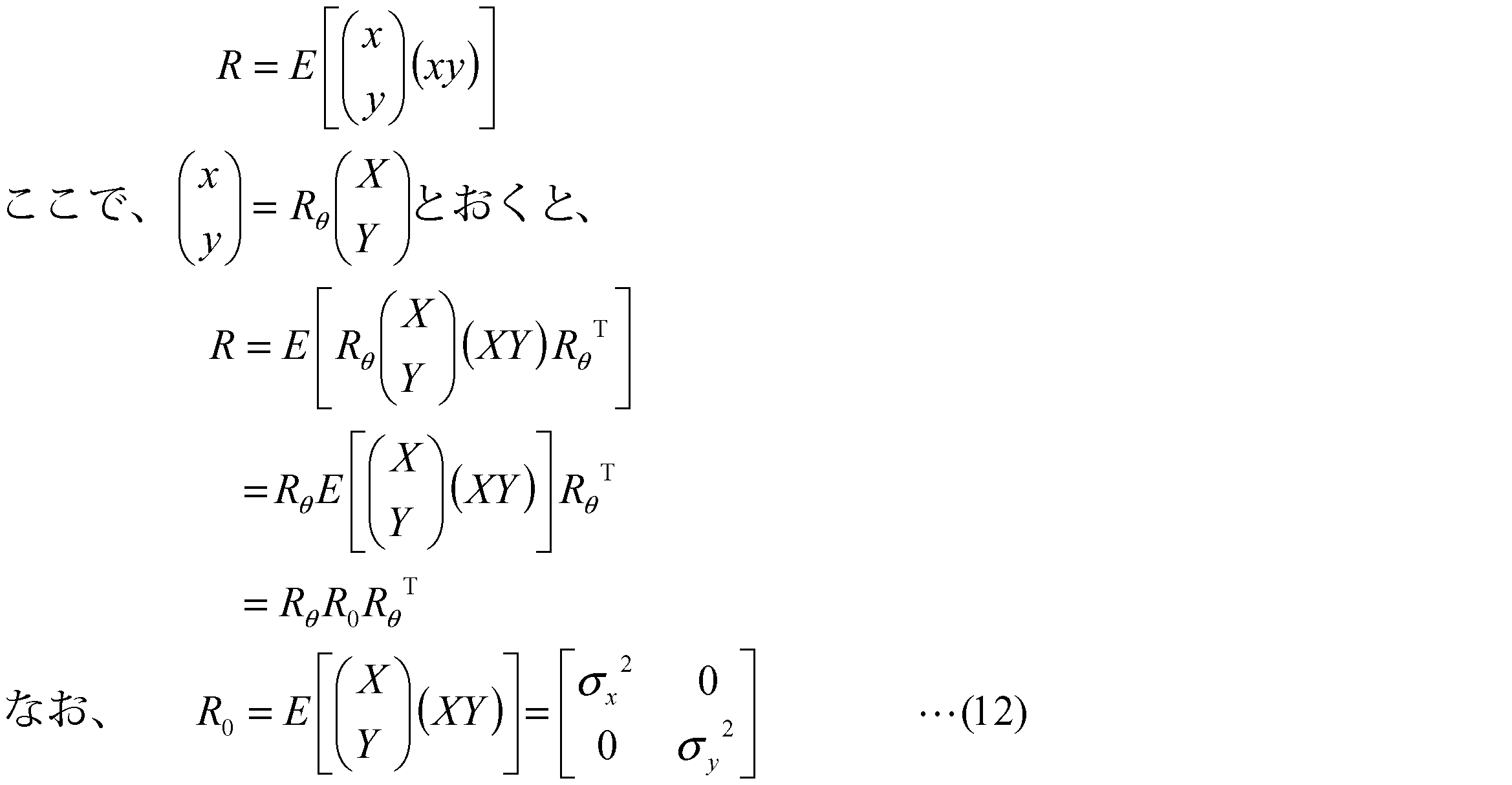
- the dispersion value R ′ at the center position in the observation noise model is represented by a perfect circle.
- the direction is perpendicular to the plane of the target vehicle.
- the variance value R at the center position in the observation noise model is changed so that the observation noise in the direction horizontal to the surface of the target vehicle is larger than the observation noise.
- the state estimation device 16 first calculates the convex hull of the grouping point cloud data generated in S1 (S41), and divides the calculated convex hull sides (S42).
- the convex hull calculation in S41 is the same as the convex hull calculation in S21 (see FIG. 12) performed by the state estimation device 16 according to the fifth embodiment.
- the state estimation device 16 fits the sides divided in S42 to one or two straight lines (S43), and calculates the azimuth angle of the fitted straight lines (S44).
- the state estimation device 16 changes the dispersion value R of the center position in the observation noise model based on the azimuth angle of the straight line calculated in S44 as represented by the above-described equation (11) (S45).
- the state estimation device 16 determines an observation model incorporating the observation noise model whose variance value has been changed in S45 as an observation model used for the current estimation (S46).
- the state estimation device 16 since the variance value of the observation noise model is changed based on the orientation of the target vehicle with respect to the surface, the accuracy of estimation of the state of the target vehicle is further improved. be able to.
- the seventh embodiment differs from the first embodiment in that only the observation noise model of the observation model is changed, but is basically the same as the first embodiment. For this reason, below, only the part which is different from 1st Embodiment is demonstrated, and description of the part similar to 1st Embodiment is abbreviate
- FIG. 16 is a diagram illustrating an estimation process of the state estimation device according to the seventh embodiment.
- the observation model is selected based on the direction of the center position of the target vehicle with respect to LIDAR2 calculated from the grouping point cloud data and the direction of the target vehicle.
- the observation noise model is changed based on the distance to the target vehicle.
- the state estimation device 17 first extracts the position of the target vehicle from the state estimated value of the target vehicle output in S9 of the previous estimation process. At this time, the state estimation device 17 is calculated from the grouping point cloud data generated in S1 of the current estimation process, as in the first embodiment, instead of the state estimation value output in S9 of the previous estimation process. The center of gravity position may be used. Next, the state estimation device 17 calculates the distance from the own vehicle to the target vehicle from the extracted position of the target vehicle. Then, the state estimation device 17 changes the observation noise in the observation noise model based on the calculated distance from the host vehicle to the target vehicle (S48).
- the state estimation device 17 increases the observation noise in the observation noise model as the distance from the host vehicle to the target vehicle increases.
- the observation noise in the observation noise model may be continuously changed according to the distance from the host vehicle to the target vehicle, for example, and is divided into one or more stages according to the distance from the host vehicle to the target vehicle. May be changed.
- the observation noise in the observation noise model can be increased every time the distance from the host vehicle to the target vehicle exceeds the set distance.
- various noises such as the center position of the surface of the target vehicle, the speed of the target vehicle, and the direction of the target vehicle can be used.
- the state estimation apparatus 17 determines the observation model incorporating the observation noise model changed in S48 as an observation model used for this estimation (S49).
- the estimation accuracy of the state of the target vehicle is further improved by changing the observation noise in the observation noise model based on the distance to the target vehicle. be able to.
- the eighth embodiment differs from the first embodiment in that only the motion noise model is changed, but is basically the same as the first embodiment. For this reason, below, only the part which is different from 1st Embodiment is demonstrated, and description of the part similar to 1st Embodiment is abbreviate
- FIG. 17 is a diagram illustrating an estimation process of the state estimation device according to the eighth embodiment.
- the observation model is changed based on the direction of the center position of the target vehicle with respect to LIDAR 2 and the direction of the target vehicle.
- the motion noise model of the motion model is changed based on the speed of the target vehicle.
- the motion noise model will be described in detail.
- the variables to be estimated are the center position (x), the center position (y), the speed (v), the direction ( ⁇ ), the tire angle ( ⁇ ), the wheel base (b), and the length (l). , Width (w) (see FIG. 2).
- the state estimation device 18 first extracts the speed of the target vehicle from the state estimated value of the target vehicle output in S9 of the previous estimation process. Then, the state estimation device 18 changes the steering change amount ⁇ ( ⁇ ) in the motion noise model based on the extracted speed of the target vehicle (S51). Specifically, the state estimation device 18 decreases the steering change amount ⁇ ( ⁇ ) in the motion noise model as the speed of the target vehicle increases.
- the steering change amount ⁇ ( ⁇ ) may be continuously changed according to the speed of the target vehicle, for example, or may be changed in one or a plurality of stages according to the speed of the target vehicle. In the latter case, for example, one or a plurality of speeds are set, and the steering change amount ⁇ ( ⁇ ) can be reduced every time the speed of the target vehicle exceeds the set speed.
- the state estimation device 18 determines the motion model incorporating the motion noise model changed in S51 as the motion model used for the current estimation (S52).
- the state estimation device 18 when the speed of the target vehicle is high, the steering change amount ⁇ ( ⁇ ) in the motion noise model is reduced, thereby estimating the state accuracy of the target vehicle. Can be further improved.
- the observation noise model used for the estimation process is changed to estimate the state of the target vehicle.
- the state of the target vehicle is estimated using a plurality of different observation models, and the state of the observation target estimated using the observation model with the smallest estimated variance value is output.
- FIG. 18 is a diagram illustrating an estimation process of the state estimation device according to the ninth embodiment.
- the state estimation device 19 prepares a plurality of different observation models (S54).
- the observation models prepared in S54 are the rear observation model, the left oblique rear observation model, the left observation model, the left oblique front observation model, the front oblique observation model, the right oblique front observation model, the right oblique observation model, and the right oblique rear observation model. It is an observation model.
- the state estimation device 19 applies the grouping point cloud data generated in S1 to the eight observation models prepared in S54, and performs Kalman filter update processing in parallel (S55).
- the Kalman filter update process in S55 is the same as the Kalman filter update process in S8 in the first embodiment.
- the state estimation device 19 determines the center position (x), the center position (y), the speed (v), the direction ( ⁇ ), the tire angle ( ⁇ ), the wheelbase (estimated in each Kalman filter update process of S55. b) Output the variables of length (l) and width (w) (S56).
- state estimation device 19 calculates an estimated variance value of each variable calculated in each Kalman filter update process in S55 (S57).
- the state estimation device 19 sets the Kalman filter output having the smallest estimated variance value among the eight Kalman filter outputs output in S56 as the final output (S59).
- the target vehicle is estimated using an appropriate observation model. Can be output.
- the Kalman filter is used as the means for estimating the state of the target vehicle.
- any means and any filter may be employed as long as the measurement data is applied to the model to estimate the state of the target vehicle.
- a particle filter may be employed.
- the peripheral vehicle existing around the own vehicle is adopted as the observation target, but any object such as a motorcycle or a bicycle may be the observation target.
- 1st Embodiment demonstrated as what changes an observation model based on the difference of the direction of the center position of the target vehicle with respect to LIDAR2, and the direction of a target vehicle, only the direction of the center position of the target vehicle with respect to LIDAR2 is demonstrated. May change the observation model, or the observation model may be changed based only on the direction of the target vehicle.
- observation model and the observation noise model may be changed by combining the first embodiment and the sixth embodiment, and the observation model is combined with the first embodiment and the eighth embodiment.
- exercise model may be changed.
- the present invention can be used as a state estimation device for estimating the state of surrounding vehicles.
Landscapes
- Physics & Mathematics (AREA)
- Engineering & Computer Science (AREA)
- General Physics & Mathematics (AREA)
- Electromagnetism (AREA)
- Remote Sensing (AREA)
- Radar, Positioning & Navigation (AREA)
- Computer Networks & Wireless Communication (AREA)
- Data Mining & Analysis (AREA)
- Mathematical Optimization (AREA)
- Theoretical Computer Science (AREA)
- Mathematical Physics (AREA)
- Pure & Applied Mathematics (AREA)
- Computational Mathematics (AREA)
- Mathematical Analysis (AREA)
- Evolutionary Biology (AREA)
- Operations Research (AREA)
- Probability & Statistics with Applications (AREA)
- Bioinformatics & Computational Biology (AREA)
- Algebra (AREA)
- Bioinformatics & Cheminformatics (AREA)
- Databases & Information Systems (AREA)
- Software Systems (AREA)
- General Engineering & Computer Science (AREA)
- Life Sciences & Earth Sciences (AREA)
- Optical Radar Systems And Details Thereof (AREA)
- Traffic Control Systems (AREA)
Abstract
Description




第1の実施形態に係る状態推定装置11の推定処理について説明する。図3は、第1の実施形態に係る状態推定装置の推定処理を示した図である。
右グルーピングの中心位置(XR)
右グルーピングの中心位置(YR)
右グルーピングにおける長軸の長さ(LR)
右グルーピングにおける長軸の方位(ΘR)
左グルーピングの中心位置(XL)
左グルーピングの中心位置(YL)
左グルーピングにおける長軸の長さ(LL)
左グルーピングにおける長軸の方位(ΘL)
となる。
XR=x-l/2×cos(θ)
YR=y-l/2×sin(θ)
LR=w
ΘR=mod(θ+π/2,π)
XL=x+w/2×sin(θ)
YL=y-w/2×cos(θ)
LL=l
ΘL=mod(θ,π)
となる。
グルーピングの中心位置(X)
グルーピングの中心位置(Y)
グルーピングにおける長軸の長さ(L)
グルーピングにおける長軸の方位(Θ)
となる。
X=x-l/2×cos(θ)
Y=y-l/2×sin(θ)
L=w
Θ=mod(θ+π/2,π)
となる。
次に、第2の実施形態に係る状態推定装置12の推定処理について説明する。第2の実施形態は、第1の実施形態と観測モデルの選択手法が異なるが、基本的に第1の実施形態と同様である。このため、以下では、第1の実施形態と相違する部分のみを説明し、第1の実施形態と同様の部分の説明を省略する。
次に、第3の実施形態に係る状態推定装置13の推定処理について説明する。第3の実施形態は、第1の実施形態と観測モデルの選択手法が異なるが、基本的に第1の実施形態と同様である。このため、以下では、第1の実施形態と相違する部分のみを説明し、第1の実施形態と同様の部分の説明を省略する。
次に、第4の実施形態に係る状態推定装置14の推定処理について説明する。第4の実施形態は、第1の実施形態と観測モデルの選択手法が異なるが、基本的に第1の実施形態と同様である。このため、以下では、第1の実施形態と相違する部分のみを説明し、第1の実施形態と同様の部分の説明を省略する。
次に、第5の実施形態に係る状態推定装置15の推定処理について説明する。第5の実施形態は、第1の実施形態と観測モデルの選択手法が異なるが、基本的に第1の実施形態と同様である。このため、以下では、第1の実施形態と相違する部分のみを説明し、第1の実施形態と同様の部分の説明を省略する。
することにしてもよい。
次に、第6の実施形態に係る状態推定装置16の推定処理について説明する。第6の実施形態は、観測モデルの観測ノイズモデルのみを変更する点で第1の実施形態と異なるが、基本的に第1の実施形態と同様である。このため、以下では、第1の実施形態と相違する部分のみを説明し、第1の実施形態と同様の部分の説明を省略する。

次に、第7の実施形態に係る状態推定装置17の推定処理について説明する。第7の実施形態は、観測モデルの観測ノイズモデルのみを変更する点で第1の実施形態と異なるが、基本的に第1の実施形態と同様である。このため、以下では、第1の実施形態と相違する部分のみを説明し、第1の実施形態と同様の部分の説明を省略する。
次に、第8の実施形態に係る状態推定装置18の推定処理について説明する。第8の実施形態は、運動ノイズモデルのみを変更する点で第1の実施形態と異なるが、基本的に第1の実施形態と同様である。このため、以下では、第1の実施形態と相違する部分のみを説明し、第1の実施形態と同様の部分の説明を省略する。
x:=x+v×cos(θ)
y:=y+v×sin(θ)
v:=v
θ:=θ+v/b×tan(ξ)
ξ:=ξ
b:=b
l:=l
w:=w
で表される。
σ(x)=0
σ(y)=0
σ(v)=加減速度
σ(θ)=0
σ(ξ)=ステアリング変化量(ステアリング角度の変化量)
σ(b)=0
σ(l)=0
σ(w)=0
となる。
次に、第9の実施形態に係る状態推定装置19の推定処理について説明する。第1の実施形態では、推定処理に用いる観測ノイズモデルを変更して、対象車両の状態を推定した。これに対し、第9の実施形態では、複数の異なる観測モデルで対象車両の状態を推定し、推定分散値が最も小さくなる観測モデルを用いて推定した観測対象の状態を出力する。
Claims (12)
- 観測対象を測定する測定装置により測定した測定データを状態推定用モデルに当てはめて前記観測対象の状態を推定する状態推定装置であって、
前記観測対象との位置関係又は前記観測対象の状態に基づいて、前記状態推定用モデルを変更する変更手段を有する、状態推定装置。 - 前記観測対象は、前記測定装置の周辺に存在する車両であり、
前記変更手段は、前記測定装置に対する前記観測対象の中心位置の方向に基づいて、前記状態推定用モデルを変更する、請求項1に記載の状態推定装置。 - 前記観測対象は、前記測定装置の周辺に存在する車両であり、
前記変更手段は、前記観測対象の向きに基づいて、前記状態推定用モデルを変更する、請求項1に記載の状態推定装置。 - 前記観測対象は、前記測定装置の周辺に存在する車両であり、
前記変更手段は、前記測定装置に対する前記観測対象の中心位置の方向、及び、前記観測対象の向き、の双方に基づいて、前記状態推定用モデルを変更する、請求項1に記載の状態推定装置。 - 前記変更手段は、前回の推定で用いた状態推定用モデルに基づいて、前記測定データを当てはめる状態推定用モデルを絞り込む、請求項1~4の何れか一項に記載の状態推定装置。
- 前記変更手段は、前回推定した前記観測対象の状態に基づいて、前記測定装置に対する前記観測対象の中心位置の方向、又は、前記観測対象の向きを推定する、請求項2~5の何れか一項に記載の状態推定装置。
- 前記変更手段は、前記観測対象が存在する位置の地図情報に基づいて、前記観測対象の向きを推定する、請求項3又は4に記載の状態推定装置。
- 前記変更手段は、測定データから前記観測対象のモデルを生成し、前記モデルを構成する辺の数に基づいて、前記状態推定用モデルを変更する、請求項1~7の何れか一項に記載の状態推定装置。
- 前記状態推定用モデルは、前記測定装置の測定により生じる観測ノイズを分散値で表す観測ノイズモデルを含み、
前記変更手段は、前記観測対象の面に対する向きに基づいて、前記観測ノイズモデルの分散値を変更する、請求項1~8の何れか一項に記載の状態推定装置。 - 前記変更手段は、前記観測対象までの距離に基づいて、前記観測ノイズモデルを変更する、請求項9に記載の状態推定装置。
- 前記観測対象は、前記測定装置の周辺に存在する車両であり、
前記状態推定用モデルは、前記周辺車両の運動状態を表す運動モデルと、前記運動モデルにおけるステアリング角度の変化量を示す運動ノイズモデルと、を含み、
前記変更手段は、前記観測対象の速度が高いと、前記観測対象の速度が低いときに比べて、前記運動ノイズモデルにおけるステアリング角度の変化量を小さくする、請求項1~10の何れか一項に記載の状態推定装置。 - 複数の異なる前記状態推定用モデルを用いて、前記観測対象の状態を推定するとともに、前記観測対象の状態の推定分散値を算出し、前記推定分散値が最も小さい前記観測対象の状態を出力する、請求項1~11の何れか一項に記載の状態推定装置。
Priority Applications (5)
| Application Number | Priority Date | Filing Date | Title |
|---|---|---|---|
| JP2013502098A JP5614489B2 (ja) | 2011-03-01 | 2011-03-01 | 状態推定装置 |
| DE112011104992.7T DE112011104992T5 (de) | 2011-03-01 | 2011-03-01 | Zustandsschätzvorrichtung |
| PCT/JP2011/054651 WO2012117528A1 (ja) | 2011-03-01 | 2011-03-01 | 状態推定装置 |
| US14/000,487 US20130332112A1 (en) | 2011-03-01 | 2011-03-01 | State estimation device |
| CN201180068185.4A CN103492903B (zh) | 2011-03-01 | 2011-03-01 | 状态推定装置 |
Applications Claiming Priority (1)
| Application Number | Priority Date | Filing Date | Title |
|---|---|---|---|
| PCT/JP2011/054651 WO2012117528A1 (ja) | 2011-03-01 | 2011-03-01 | 状態推定装置 |
Publications (1)
| Publication Number | Publication Date |
|---|---|
| WO2012117528A1 true WO2012117528A1 (ja) | 2012-09-07 |
Family
ID=46757490
Family Applications (1)
| Application Number | Title | Priority Date | Filing Date |
|---|---|---|---|
| PCT/JP2011/054651 Ceased WO2012117528A1 (ja) | 2011-03-01 | 2011-03-01 | 状態推定装置 |
Country Status (5)
| Country | Link |
|---|---|
| US (1) | US20130332112A1 (ja) |
| JP (1) | JP5614489B2 (ja) |
| CN (1) | CN103492903B (ja) |
| DE (1) | DE112011104992T5 (ja) |
| WO (1) | WO2012117528A1 (ja) |
Cited By (8)
| Publication number | Priority date | Publication date | Assignee | Title |
|---|---|---|---|---|
| JP2014066679A (ja) * | 2012-09-27 | 2014-04-17 | Ihi Corp | デバイスの状態同定方法と装置 |
| WO2015098222A1 (ja) * | 2013-12-26 | 2015-07-02 | 三菱電機株式会社 | 情報処理装置及び情報処理方法及びプログラム |
| JP2017056935A (ja) * | 2015-09-14 | 2017-03-23 | トヨタ モーター エンジニアリング アンド マニュファクチャリング ノース アメリカ,インコーポレイティド | 3dセンサにより検出されたオブジェクトの分類 |
| JP2018159574A (ja) * | 2017-03-22 | 2018-10-11 | 本田技研工業株式会社 | レーザ式測距装置のノイズデータの特定方法 |
| US10410072B2 (en) | 2015-11-20 | 2019-09-10 | Mitsubishi Electric Corporation | Driving support apparatus, driving support system, driving support method, and computer readable recording medium |
| WO2019181491A1 (ja) * | 2018-03-22 | 2019-09-26 | 日立オートモティブシステムズ株式会社 | 物体認識装置 |
| JP2022014269A (ja) * | 2020-07-06 | 2022-01-19 | トヨタ自動車株式会社 | 車両及び他車両の認識方法 |
| JP2023121505A (ja) * | 2022-02-21 | 2023-08-31 | 沖電気工業株式会社 | 信号処理システム |
Families Citing this family (10)
| Publication number | Priority date | Publication date | Assignee | Title |
|---|---|---|---|---|
| US9563530B2 (en) * | 2013-12-03 | 2017-02-07 | Kabushiki Kaisha Toshiba | Device state estimation apparatus, device power consumption estimation apparatus, and program |
| CN104730537B (zh) * | 2015-02-13 | 2017-04-26 | 西安电子科技大学 | 基于多尺度模型的红外/激光雷达数据融合目标跟踪方法 |
| US10557942B2 (en) * | 2016-06-07 | 2020-02-11 | DSCG Solutions, Inc. | Estimation of motion using LIDAR |
| EP3470878B1 (de) * | 2017-10-13 | 2023-04-19 | Leuze electronic GmbH + Co. KG | Optischer sensor |
| US10408638B2 (en) * | 2018-01-04 | 2019-09-10 | Mitsubishi Electric Research Laboratories, Inc. | System and method for controlling a vehicle under sensor uncertainty |
| US10369923B1 (en) * | 2018-04-30 | 2019-08-06 | Automotive Research & Testing Center | Operation method of adaptive driving beam headlamp system |
| DE102018206751A1 (de) * | 2018-05-02 | 2019-11-07 | Continental Automotive Gmbh | Konturerkennung eines fahrzeugs anhand von messdaten einer umfeldsensorik |
| US11420647B2 (en) * | 2020-08-13 | 2022-08-23 | Argo AI, LLC | Enhanced static object classification using lidar |
| EP4148460A1 (de) * | 2021-09-13 | 2023-03-15 | Leuze electronic GmbH + Co. KG | Optischer sensor und verfahren zur detektion von objekten mittels eines optischen sensors |
| KR20240123114A (ko) * | 2023-02-06 | 2024-08-13 | 현대자동차주식회사 | 충돌 방지 보조 장치 및 방법 |
Citations (3)
| Publication number | Priority date | Publication date | Assignee | Title |
|---|---|---|---|---|
| JP2005274300A (ja) * | 2004-03-24 | 2005-10-06 | Mitsubishi Electric Corp | 目標追尾装置 |
| JP2009042181A (ja) * | 2007-08-10 | 2009-02-26 | Denso Corp | 推定装置 |
| JP2009128298A (ja) * | 2007-11-27 | 2009-06-11 | Mitsubishi Electric Corp | 目標追尾装置 |
Family Cites Families (8)
| Publication number | Priority date | Publication date | Assignee | Title |
|---|---|---|---|---|
| US6121919A (en) * | 1999-07-23 | 2000-09-19 | Eaton-Vorad Technologies, L.L.C. | Method and apparatus for range correction in a radar system |
| US6628227B1 (en) * | 2002-07-23 | 2003-09-30 | Ford Global Technologies, Llc | Method and apparatus for determining a target vehicle position from a source vehicle using a radar |
| JP4433887B2 (ja) * | 2003-07-01 | 2010-03-17 | 日産自動車株式会社 | 車両用外界認識装置 |
| US8855848B2 (en) * | 2007-06-05 | 2014-10-07 | GM Global Technology Operations LLC | Radar, lidar and camera enhanced methods for vehicle dynamics estimation |
| JP2009098023A (ja) * | 2007-10-17 | 2009-05-07 | Toyota Motor Corp | 物体検出装置及び物体検出方法 |
| US20090292468A1 (en) * | 2008-03-25 | 2009-11-26 | Shunguang Wu | Collision avoidance method and system using stereo vision and radar sensor fusion |
| JP5051468B2 (ja) * | 2008-12-25 | 2012-10-17 | トヨタ自動車株式会社 | センサ校正装置、及び、センサ校正方法 |
| FR2953021B1 (fr) * | 2009-11-26 | 2011-12-09 | Tanguy Griffon | Methode de mesure des emissions hebdomadaires et annuelles d'un gaz a effet de serre sur une surface donnee |
-
2011
- 2011-03-01 CN CN201180068185.4A patent/CN103492903B/zh not_active Expired - Fee Related
- 2011-03-01 WO PCT/JP2011/054651 patent/WO2012117528A1/ja not_active Ceased
- 2011-03-01 US US14/000,487 patent/US20130332112A1/en not_active Abandoned
- 2011-03-01 JP JP2013502098A patent/JP5614489B2/ja not_active Expired - Fee Related
- 2011-03-01 DE DE112011104992.7T patent/DE112011104992T5/de not_active Withdrawn
Patent Citations (3)
| Publication number | Priority date | Publication date | Assignee | Title |
|---|---|---|---|---|
| JP2005274300A (ja) * | 2004-03-24 | 2005-10-06 | Mitsubishi Electric Corp | 目標追尾装置 |
| JP2009042181A (ja) * | 2007-08-10 | 2009-02-26 | Denso Corp | 推定装置 |
| JP2009128298A (ja) * | 2007-11-27 | 2009-06-11 | Mitsubishi Electric Corp | 目標追尾装置 |
Cited By (13)
| Publication number | Priority date | Publication date | Assignee | Title |
|---|---|---|---|---|
| JP2014066679A (ja) * | 2012-09-27 | 2014-04-17 | Ihi Corp | デバイスの状態同定方法と装置 |
| WO2015098222A1 (ja) * | 2013-12-26 | 2015-07-02 | 三菱電機株式会社 | 情報処理装置及び情報処理方法及びプログラム |
| JP6091658B2 (ja) * | 2013-12-26 | 2017-03-08 | 三菱電機株式会社 | 情報処理装置及び情報処理方法及びプログラム |
| JP2017056935A (ja) * | 2015-09-14 | 2017-03-23 | トヨタ モーター エンジニアリング アンド マニュファクチャリング ノース アメリカ,インコーポレイティド | 3dセンサにより検出されたオブジェクトの分類 |
| US10410072B2 (en) | 2015-11-20 | 2019-09-10 | Mitsubishi Electric Corporation | Driving support apparatus, driving support system, driving support method, and computer readable recording medium |
| JP2018159574A (ja) * | 2017-03-22 | 2018-10-11 | 本田技研工業株式会社 | レーザ式測距装置のノイズデータの特定方法 |
| WO2019181491A1 (ja) * | 2018-03-22 | 2019-09-26 | 日立オートモティブシステムズ株式会社 | 物体認識装置 |
| JPWO2019181491A1 (ja) * | 2018-03-22 | 2021-01-14 | 日立オートモティブシステムズ株式会社 | 物体認識装置 |
| US11982745B2 (en) | 2018-03-22 | 2024-05-14 | Hitachi Astemo, Ltd. | Object recognizing device |
| JP2022014269A (ja) * | 2020-07-06 | 2022-01-19 | トヨタ自動車株式会社 | 車両及び他車両の認識方法 |
| JP7318600B2 (ja) | 2020-07-06 | 2023-08-01 | トヨタ自動車株式会社 | 車両及び他車両の認識方法 |
| JP2023121505A (ja) * | 2022-02-21 | 2023-08-31 | 沖電気工業株式会社 | 信号処理システム |
| JP7838300B2 (ja) | 2022-02-21 | 2026-04-01 | 沖電気工業株式会社 | 信号処理システム |
Also Published As
| Publication number | Publication date |
|---|---|
| JPWO2012117528A1 (ja) | 2014-07-07 |
| CN103492903B (zh) | 2015-04-01 |
| CN103492903A (zh) | 2014-01-01 |
| DE112011104992T5 (de) | 2014-01-23 |
| US20130332112A1 (en) | 2013-12-12 |
| JP5614489B2 (ja) | 2014-10-29 |
Similar Documents
| Publication | Publication Date | Title |
|---|---|---|
| JP5614489B2 (ja) | 状態推定装置 | |
| US9797981B2 (en) | Moving-object position/attitude estimation apparatus and moving-object position/attitude estimation method | |
| US11300415B2 (en) | Host vehicle position estimation device | |
| JP7487388B2 (ja) | 測定装置、測定方法、及び、プログラム | |
| JP2005025458A (ja) | 車両用外界認識装置 | |
| JP2012145444A (ja) | 歩行者検出装置 | |
| CN106796291A (zh) | 车载用物体判别装置 | |
| JP7118717B2 (ja) | 画像処理装置およびステレオカメラ装置 | |
| CN103180756A (zh) | 速度确定设备 | |
| KR20150106200A (ko) | 차량 레이더 오차 보정 시스템 및 그 방법 | |
| US20210245777A1 (en) | Map generation device, map generation system, map generation method, and storage medium | |
| WO2022098516A1 (en) | Systems and methods for radar false track mitigation with camera | |
| JP6834914B2 (ja) | 物体認識装置 | |
| JP2015161545A (ja) | 車両挙動予測装置及びプログラム | |
| JP7308141B2 (ja) | 自己位置推定方法及び自己位置推定装置 | |
| US10186154B2 (en) | Device and method for detecting surrounding vehicles | |
| JP5682302B2 (ja) | 走行道路推定装置、方法およびプログラム | |
| JP4506163B2 (ja) | 前方物体検出装置及び前方物体検出方法 | |
| JPWO2019123582A1 (ja) | 物体情報生成装置及び物体情報生成プログラム | |
| JP2008003662A (ja) | 車両識別システム | |
| US12552368B2 (en) | Vehicle position estimation system with sensing for object detection and estimation of feature points | |
| US11662454B2 (en) | Systems and methods for range-rate dealiasing using position consistency | |
| US20240331407A1 (en) | Own-vehicle position estimation device, vehicle control system, and own-vehicle position estimation method | |
| KR20190094880A (ko) | 차량간 거리 추정 장치 및 방법 | |
| CN120693540A (zh) | 物体检测装置及物体检测方法 |
Legal Events
| Date | Code | Title | Description |
|---|---|---|---|
| 121 | Ep: the epo has been informed by wipo that ep was designated in this application |
Ref document number: 11860070 Country of ref document: EP Kind code of ref document: A1 |
|
| ENP | Entry into the national phase |
Ref document number: 2013502098 Country of ref document: JP Kind code of ref document: A |
|
| WWE | Wipo information: entry into national phase |
Ref document number: 14000487 Country of ref document: US |
|
| WWE | Wipo information: entry into national phase |
Ref document number: 112011104992 Country of ref document: DE Ref document number: 1120111049927 Country of ref document: DE |
|
| 122 | Ep: pct application non-entry in european phase |
Ref document number: 11860070 Country of ref document: EP Kind code of ref document: A1 |