WO2012115083A1 - 空間情報検出装置 - Google Patents
空間情報検出装置 Download PDFInfo
- Publication number
- WO2012115083A1 WO2012115083A1 PCT/JP2012/054064 JP2012054064W WO2012115083A1 WO 2012115083 A1 WO2012115083 A1 WO 2012115083A1 JP 2012054064 W JP2012054064 W JP 2012054064W WO 2012115083 A1 WO2012115083 A1 WO 2012115083A1
- Authority
- WO
- WIPO (PCT)
- Prior art keywords
- signal
- light
- charge
- unit
- amount
- Prior art date
Links
Images


Classifications
-
- G—PHYSICS
- G01—MEASURING; TESTING
- G01B—MEASURING LENGTH, THICKNESS OR SIMILAR LINEAR DIMENSIONS; MEASURING ANGLES; MEASURING AREAS; MEASURING IRREGULARITIES OF SURFACES OR CONTOURS
- G01B11/00—Measuring arrangements characterised by the use of optical techniques
- G01B11/02—Measuring arrangements characterised by the use of optical techniques for measuring length, width or thickness
-
- G—PHYSICS
- G01—MEASURING; TESTING
- G01S—RADIO DIRECTION-FINDING; RADIO NAVIGATION; DETERMINING DISTANCE OR VELOCITY BY USE OF RADIO WAVES; LOCATING OR PRESENCE-DETECTING BY USE OF THE REFLECTION OR RERADIATION OF RADIO WAVES; ANALOGOUS ARRANGEMENTS USING OTHER WAVES
- G01S17/00—Systems using the reflection or reradiation of electromagnetic waves other than radio waves, e.g. lidar systems
- G01S17/02—Systems using the reflection of electromagnetic waves other than radio waves
- G01S17/06—Systems determining position data of a target
- G01S17/08—Systems determining position data of a target for measuring distance only
- G01S17/32—Systems determining position data of a target for measuring distance only using transmission of continuous waves, whether amplitude-, frequency-, or phase-modulated, or unmodulated
-
- G—PHYSICS
- G01—MEASURING; TESTING
- G01S—RADIO DIRECTION-FINDING; RADIO NAVIGATION; DETERMINING DISTANCE OR VELOCITY BY USE OF RADIO WAVES; LOCATING OR PRESENCE-DETECTING BY USE OF THE REFLECTION OR RERADIATION OF RADIO WAVES; ANALOGOUS ARRANGEMENTS USING OTHER WAVES
- G01S17/00—Systems using the reflection or reradiation of electromagnetic waves other than radio waves, e.g. lidar systems
- G01S17/88—Lidar systems specially adapted for specific applications
- G01S17/89—Lidar systems specially adapted for specific applications for mapping or imaging
- G01S17/894—3D imaging with simultaneous measurement of time-of-flight at a 2D array of receiver pixels, e.g. time-of-flight cameras or flash lidar
-
- G—PHYSICS
- G01—MEASURING; TESTING
- G01S—RADIO DIRECTION-FINDING; RADIO NAVIGATION; DETERMINING DISTANCE OR VELOCITY BY USE OF RADIO WAVES; LOCATING OR PRESENCE-DETECTING BY USE OF THE REFLECTION OR RERADIATION OF RADIO WAVES; ANALOGOUS ARRANGEMENTS USING OTHER WAVES
- G01S7/00—Details of systems according to groups G01S13/00, G01S15/00, G01S17/00
- G01S7/48—Details of systems according to groups G01S13/00, G01S15/00, G01S17/00 of systems according to group G01S17/00
- G01S7/491—Details of non-pulse systems
- G01S7/4912—Receivers
- G01S7/4915—Time delay measurement, e.g. operational details for pixel components; Phase measurement
Definitions
- the present invention relates to a spatial information detection device, and more particularly, by projecting light into a space to be detected and receiving light from the space, the distance to an object existing in the space, the reflectance or absorption of the object present in the space.
- the present invention relates to an active type spatial information detection device that detects spatial information such as a rate, a reflectance or absorption rate of a medium in the space, and the presence or absence of an object in the space.
- an active type spatial information detection device that detects spatial information by projecting light into a detection target space and receiving light from the space.
- This type of spatial information detection device detects spatial information such as the distance to an object existing in the space, the reflectance of the object present in the space, the transmittance of the medium in the space, and the presence or absence of the object in the space.
- Each is configured according to the type of spatial information to be detected.
- Spatial information detection devices that detect the distance to an object existing in space as spatial information include a time-of-flight method (time-of-flight method) that measures the time until the projected light is received after being reflected by the object. A configuration using the principle of) is known. The measured time is converted into a distance to the object.
- time-of-flight method time-of-flight method
- This type of spatial information detection device projects intensity-modulated light (hereinafter referred to as “signal light”) having a modulated waveform whose intensity changes at a constant period, such as a sine waveform, and projects signal light.
- the phase difference of the modulation waveform between the time point and the light reception time point is measured. Since the period of the modulation waveform is constant, the distance to the object is obtained from the phase difference. (For example, see Document 1 [Japan Published Patent Publication No. 2004-45304]).
- the phase difference is calculated by obtaining the charge corresponding to the amount of received light at a plurality of timings synchronized with the signal light and using the charge relationship at each timing.
- This phase difference corresponds to the time difference from when the projected signal light is reflected by the object until it is received, so the period of the signal light is T [s], the speed of light is c [m / s], and the modulation waveform
- the phase difference is ⁇ [radian]
- the frequency of the signal light is 20 MHz
- the period T is 50 [ns]
- the maximum measurable distance (hereinafter referred to as “measurement maximum distance”) is 7.5 [m]. That is, since the signal light whose intensity changes at a constant period is used, the upper limit of the measurable range is a distance corresponding to the half period of the signal light (half wavelength distance).
- a spatial information detection device that detects spatial information such as the reflectance and absorption rate of objects, the reflectance and absorption rate of media, and the presence or absence of objects
- a light projection period in which signal light is projected into space and a signal in space
- a non-projection period in which light is not projected is provided.
- environment light the influence of ambient light or ambient light
- the amount of light received during the non-projection period is the amount of light received only corresponding to the ambient light
- the amount of light received during the light projection period is the amount of light received corresponding to the ambient light and the projected signal light.
- the apparatus removes a component corresponding to ambient light based on the amount of light received during the light projection period and the amount of light received during the non-light projection period, and extracts a component corresponding to the reflected light of the signal light. In other words, spatial information corresponding to the intensity of the reflected light of the signal light is detected.
- an image sensor is used for light reception from space.
- a distance image with each pixel value as a distance value is generated, and the intensity of reflected light is obtained.
- a grayscale image having each pixel value as an intensity value is generated.
- the spatial information is detected by the reflected light of the signal light projected on the space. Therefore, if there is a transparent object such as glass that transmits light between the space where the spatial information is to be detected and the spatial information detection device, the light from the space from which the spatial information is detected and the transparent information Both reflected light from the object may be received. In this case, the reflected light from the transparent object is superimposed on the light from the space, and components other than the space are included in the amount of received light, resulting in a problem that the spatial information cannot be accurately detected.
- a transparent object such as glass that transmits light between the space where the spatial information is to be detected and the spatial information detection device
- the reflected light mainly diffuse reflected light
- the vicinity of the spatial information detection device substantially means a region between the space to be detected as the spatial information and the spatial information detection device.
- non-target object an object that is not a target for detecting spatial information
- reflected light from the non-target object is reflected. It is superimposed on the light from the space and enters the spatial information detection device.
- the spatial information detection device cannot accurately detect the spatial information.
- the present invention provides spatial information that improves detection accuracy of spatial information by removing the influence of the non-target object even when a non-target object exists between the space that is the detection target of the spatial information.
- An object is to provide a detection device.
- a spatial information detection device includes a light projecting unit that emits signal light to a space including a predetermined target area, a light receiving unit that receives light from the space, and a modulation signal.
- a modulation signal generating unit that outputs to the light projecting unit, a demodulated signal generating unit that generates a demodulated signal and outputs the demodulated signal to the light receiving unit, an arithmetic unit that generates spatial information about the target area, a correction information providing unit, Is provided.
- the modulation signal is a square wave signal in which the length of the high-level period and the low-level period is randomly determined from a length that is an integral multiple of a predetermined unit period.
- the light projecting unit is configured to generate the signal light by modulating the light with the modulation signal when the modulation signal is received.
- the demodulated signal is a signal having the same waveform as the modulated signal or the inverted modulated signal.
- the light receiving unit corresponds to the intensity of light received from the space during an integration period defined by one of a first period in which the demodulated signal is at a high level and a second period in which the demodulated signal is at a low level. An electric charge is generated, and the electric charge generated during the integration period is accumulated over a predetermined accumulation period longer than the integration period to generate a signal charge.
- the correction information providing unit is configured to generate correction information related to charges generated in the light receiving unit due to light from a non-target area between the light projecting unit and the light receiving unit and the target area. Is done.
- the calculation unit corrects the amount of the signal charge to the amount of target charge corresponding to the charge generated in the light receiving unit due to light from the target area using the correction information, and the target charge
- the spatial information is configured to be generated based on the amount of.
- the spatial information detection device includes, in the first aspect, a search signal generation unit that generates a search signal and outputs the search signal to the light receiving unit.
- the search signal is a signal having a predetermined time difference with respect to the modulated signal.
- the correction information providing unit includes a phase variable unit and a correction information calculation unit.
- the light receiving unit has an intensity of light received from the space during a second integration period defined by one of a first period in which the search signal is at a high level and a second period in which the search signal is at a low level. And generating a correction charge by accumulating the charge generated during the second integration period over a predetermined second accumulation period longer than the second integration period. .
- the phase variable unit is configured to change the time difference within a predetermined time range with a change width smaller than the unit period so that the search signal generation unit generates the plurality of search signals having different time differences.
- the correction information calculation unit is configured to acquire the correction charge from the light receiving unit for each search signal having a different time difference and generate the correction information based on a relationship between the time difference and the amount of the correction charge. Is done.
- the spatial information is a distance to an object existing in the target area.
- the calculation unit calculates, from the amount of the target charge, a flight time required for the light receiving unit to receive the signal light reflected from the object after the signal light is emitted from the light projecting unit, The distance is determined based on the flight time.
- the correction information includes a non-target component and a non-target flight time.
- the non-target component is an amount of non-target charge corresponding to the charge generated in the light receiving unit due to light from the non-target area.
- the non-target flight time is a time taken for the light receiving unit to receive the signal light reflected by a non-target object existing in the non-target area after the signal light is emitted from the light projecting unit.
- the correction information calculation unit is configured to calculate a change rate of the amount of the correction charge with respect to the time difference.
- the correction information calculation unit is configured to obtain a product of the change rate in the range in which the amount of the correction charge linearly changes with respect to the time difference and the unit period as the non-target component.
- the correction information calculation unit is configured to obtain the time difference when the change rate changes to 0 as the non-target flight time.
- the calculation unit is configured to store in advance a conversion formula for converting the amount of the signal charge into the amount of the target charge using the non-target component and the non-target flight time.
- the calculation unit is configured to correct the amount of the signal charge to the amount of the target charge using the non-target component and the non-target flight time obtained from the correction information providing unit and the conversion formula. Is done.
- the demodulated signal generation unit is configured to generate a plurality of the demodulated signals.
- the plurality of demodulated signals include a first demodulated signal having the same waveform as the modulated signal, a second demodulated signal obtained by inverting the first demodulated signal, and the first demodulated signal from the first demodulated signal. It includes two of a third demodulated signal that is delayed by a unit period and a fourth demodulated signal that is a signal obtained by inverting the third demodulated signal.
- the spatial information is a reflection intensity of the signal light in the target area.
- the correction information includes a non-target component.
- the non-target component is an amount of non-target charge corresponding to the charge generated in the light receiving unit due to light from the non-target area.
- the correction information calculation unit is configured to obtain a change rate of the correction charge amount with respect to the time difference.
- the correction information calculation unit is configured to obtain, as the non-target component, a product of the change rate and the unit period in a range in which the amount of the correction charge linearly changes with respect to the time difference.
- the calculation unit is configured to store in advance a conversion formula for converting the amount of the signal charge into the amount of the target charge using the non-target component.
- the calculation unit is configured to correct the amount of the signal charge to the amount of the target charge using the non-target component obtained from the correction information providing unit and the conversion formula.
- the light projecting unit emits the signal light during a light projection period and does not emit the signal light during a non-light projection period.
- the calculation unit is configured to obtain the reflection intensity based on a difference between the amount of the target charge corresponding to the light projection period and the amount of the target charge corresponding to the non-light projection period.
- the correction information providing unit receives the correction charge not including the target charge from the light receiving unit.
- a range setting unit for designating an effective range of the obtained time difference is provided.
- the correction information calculation unit is configured to generate the correction information based on a relationship between the time difference within the effective range specified by the range setting unit and the amount of the correction charge.
- the correction information providing unit is configured to perform the correction based on a relationship between the time difference within the predetermined time range and the amount of the correction charge.
- a correction information acquisition unit for determining an effective range is provided.
- the range setting unit is configured to specify the effective range determined by the correction information acquisition unit.
- the correction information providing unit determines whether a predetermined update condition is satisfied, and If it is determined that the update condition is satisfied, the correction information is updated.
- FIG. 1 It is a block diagram which shows the spatial information detection apparatus of Embodiment 1. It is a side view which shows the usage example of the spatial information detection apparatus of the said Embodiment 1. It is a side view which shows the usage example of the spatial information detection apparatus of the said Embodiment 1. It is operation
- a distance measurement device that measures the distance to an object that exists in the space to be detected, and the reflected light of the object that exists in the space to be detected
- An intensity detection device that detects intensity is illustrated.
- a distance image having a pixel value as a distance value is generated, and when detecting the intensity of reflected light, the pixel value is a gray value.
- An example of generating an image is shown.
- a configuration in which a light receiving element including a single light receiving region (photoelectric conversion unit) in the light receiving unit is used to measure the distance and the intensity of reflected light may be employed.
- strength detection apparatus is each demonstrated.
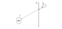
- the distance measuring device includes a light projecting unit 11 that projects light into a space to be detected, and a light receiving unit 12 that receives light from the space.
- the light projected from the light projecting unit 11 (hereinafter referred to as “signal light”) is reflected by the object 1 and reflected from the object 1 by the light receiving unit 12.
- the distance to the object 1 is measured by measuring a physical quantity corresponding to the time (flight time) from when the signal light is projected from the light projecting unit 11 to when it is received by the light receiving unit 12. That is, the distance measuring apparatus shown in the figure measures the distance using the principle of time-of-flight method (time-of-flight method).
- the light projecting unit 11 is configured to emit signal light into a space including a predetermined target area.
- the target area is, for example, a space where the object 1 exists.
- the light projecting unit 11 includes a light emitting source 111 composed of a light emitting element such as a light emitting diode or a laser diode, and a light projecting optical system 112 that adjusts the light projecting range of the signal light emitted from the light emitting source 111.
- the light receiving unit 12 is configured to receive light from the space.
- the light receiving unit 12 includes an image sensor 121 such as a CCD area image sensor or a CMOS area image sensor, and a light receiving optical system 122 that adjusts the field of view of the image sensor 121.
- the light emitting element used for the light emitting source 111 modulates the light output at a high frequency (for example, 10 MHz), and the image sensor 121 detects a change in the received light intensity for the same time as the light output of the light emitting source 111 changes.
- the light emitting source 111 may include only one light emitting element, but it is preferable to combine a plurality of light emitting elements in order to increase the light output and reach the signal light far away.
- a lens is usually used, but a mirror may be used, or a lens and a mirror may be used in combination.
- the imaging element 121 uses an electronic shutter principle to control an integration period for accumulating charges obtained by photoelectric conversion, and performs many times (for example, 10,000 times) for each light receiving region (photoelectric conversion unit) that performs photoelectric conversion. ) Accumulated charge accumulated one by one.
- a period for accumulating charges is referred to as an “accumulation period”.
- the accumulation period is set to a short time that allows the received light intensity to be considered constant.
- the imaging element 121 not only has the function of the light receiving unit 12 that generates a charge corresponding to the amount of received light, but also has a predetermined accumulation period in which the charge generated by the light receiving unit 12 is sufficiently longer than the integration period.
- a charge storage unit is usually provided separately from the light receiving element.
- the light receiving unit 12 includes the photoelectric conversion unit and the charge storage unit 123.
- the photoelectric conversion unit is configured to generate an electric charge according to the intensity of light received from the space during an integration period defined by a period in which the demodulated signal is at a high level.
- the charge accumulation unit 123 is configured to accumulate charges generated during the integration period over a predetermined accumulation period longer than the integration period, and output the accumulated charges to the arithmetic unit 30 as signal charges. .
- the integration period may be defined as a period in which the demodulated signal is at a low level. That is, the light receiving unit 12 corresponds to the intensity of light received from the space during the integration period defined by either the first period when the demodulated signal is high level or the second period when the demodulated signal is low level. An electric charge may be generated.
- the image sensor 121 is an FT-type CCD image sensor
- the light receiving area photoelectric conversion unit
- the charge accumulation unit 123 corresponds to the accumulation area.
- the light receiving area corresponds to a pixel in each imaging area
- the charge storage unit 123 corresponds to a vertical transfer unit. Note that the transfer unit provided in the imaging element 121 functions as a charge extraction unit that extracts charges.
- the number of times of taking out the charge from the image sensor 121 to the outside can be set to 30 times or more per second even if the number of times of accumulation is about 10,000. That is, it is possible to obtain a moving image having a smooth motion with respect to a distance image whose pixel value is a distance value.
- the distance to the object 1 is the relationship between the signal pattern (signal waveform) of the modulation signal that modulates the intensity of the signal light projected from the light source 111 and the integration period in the image sensor 121 corresponding to this signal pattern. It is calculated using.
- the modulation signal is a rectangular wave signal in which the measurement period of each of the binary signal values of H level (high level) and L level (low level) is changed randomly.
- the H level and the L level are generated without periodicity, and the generation probabilities of the H level and the L level are equal. That is, the modulation signal is a square wave signal in which the length of the high level period and the low level period is determined randomly from the length of an integral multiple of a predetermined unit period.
- “1” indicates the H level and “0” indicates the L level.
- Such a modulation signal is generated from a reference signal generated using a technique (for example, a Gold code generation circuit) that generates a PN (Pseudorandom Noise) code used in the spread spectrum technique. Similar to the PN code, the reference signal is generated so that each period of the H level and the L level has a length that is an integral multiple of the unit period. Hereinafter, this unit period is referred to as a chip length following the PN code. The chip length can be set appropriately. The chip length is set to 100 [ns], for example.
- a code generator 31 is provided to generate a reference signal, and the reference signal output from the code generator 31 is input to the modulation signal generation unit 32.
- the modulation signal generation unit 32 generates a modulation signal from the reference signal.
- the modulation signal generated by the modulation signal generation unit 32 is given to the light emission source 111.
- the light source 111 is turned on during a period when the modulation signal is at the H level, and is turned off during a period when the modulation signal is at the L level.
- the light source 111 is turned on and off according to the signal value of the modulation signal, and projects signal light whose intensity changes in a rectangular wave shape into the space.
- the light projecting unit 11 is configured to generate signal light by modulating light with the modulation signal when receiving the modulation signal.
- the reference signal output from the code generator 31 is also input to the demodulated signal generator 33.
- the demodulated signal generation unit 33 generates a demodulated signal that specifies an integration period in which charges are accumulated in each light receiving unit 12 of the image sensor 121.
- the demodulated signal generation unit 33 is configured to generate a demodulated signal and output it to the light receiving unit 12.
- the demodulated signal is a signal having the same waveform as the modulated signal or the inverted modulated signal.
- the demodulated signal generation unit 33 of the present embodiment generates four different demodulated signals in order to generate one distance image.
- a timing signal for controlling the timing at which the electric charge accumulated in the image sensor 121 is extracted to the outside and the operation timing of the arithmetic unit 30 described later is generated by a timing signal generator (not shown) separately from the code generator 31.
- the calculation unit 30 includes a microcomputer as a main component, and implements the functions of the calculation unit 30 described below by executing an appropriate program on the microcomputer.
- the modulation signal output from the modulation signal generation unit 32 matches the phase of the reference signal generated by the code generator 31
- the reference signal generated by the code generator 31 may be used as one of the demodulated signals, and the phase of the modulation signal may be shifted with respect to the reference signal.
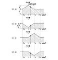
- FIG. 4 shows the relationship between the modulated signal and each demodulated signal.
- 4A shows the modulation signal (the intensity of the signal light)
- FIG. 4B shows the intensity of the light received by the image sensor 121.
- the demodulated signal is generated so as to have the following relationship with the modulated signal.
- Two of the four types of demodulated signals are a first demodulated signal that is a non-inverted signal of the modulated signal as shown in FIG. 4C, and the modulated signal is at the H level as shown in FIG.
- the second demodulated signal is an inverted signal obtained by inverting the L level.
- the remaining two kinds of demodulated signals include a third demodulated signal obtained by delaying the non-inverted signal of the modulated signal by one chip length Tc as shown in FIG. 4E and a modulated signal as shown in FIG.
- the inverted signal is delayed by one chip length Tc and becomes the fourth demodulated signal in which the H level and the L level are inverted.
- each demodulated signal is generated as a prescribed relationship with the modulated signal.
- the demodulated signal generation unit 33 of the present embodiment is configured to generate a plurality (four) of demodulated signals.
- the plurality of demodulated signals include a first demodulated signal having the same waveform as the modulated signal, a second demodulated signal obtained by inverting the first demodulated signal, and a unit period (one chip) from the first demodulated signal. 3) a third demodulated signal that is delayed by Tc and a fourth demodulated signal that is an inverted version of the third demodulated signal.
- the time (flight time) until the reflected light obtained by reflecting the signal light projected from the light emitting source 111 on the object 1 is received by the image sensor 121 varies depending on the distance to the object 1, and is shown in FIG. As shown in b), the received light intensity changes. Therefore, when the integration period of the image sensor 121 is specified by any one of the above-described four types of demodulated signals, the amount of charge integrated in the image sensor 121 corresponding to the signal light is shown in FIGS. 4 (c) to 4 (f). The amount corresponds to the area of the part indicated by the hatched portion.
- the integration period of the image sensor 121 is controlled by each one type of demodulated signal selected from the four types of demodulated signals, and charge is taken out from the image sensor 121 for each type of integration period, the four types of demodulated signals are designated.
- the amount of charge for each integration period can be obtained.
- the charge amounts obtained corresponding to the demodulated signals are A0, A2, A1, and A3, respectively.
- the amount of charge accumulated during the accumulation period (first demodulated signal) accumulated during the accumulation period specified by the demodulated signal (first demodulated signal) that matches the modulated signal. A0) is defined as A0.
- the amount of charge accumulated during the accumulation period (the first charge amount accumulated during the accumulation period) specified by the demodulated signal (second demodulated signal) obtained by inverting the first demodulated signal. (Amount of signal charge corresponding to the demodulated signal 2) is A2.
- the charge accumulated in the integration period specified by the demodulated signal (third demodulated signal) shifted by one chip length Tc from the modulation signal is accumulated over the accumulation period.
- A1 be the amount of charge (the amount of signal charge corresponding to the third demodulated signal).
- FIG. 4F the amount of charge accumulated during the accumulation period (the first charge amount accumulated in the accumulation period specified by the demodulated signal (fourth demodulated signal) obtained by inverting the third demodulated signal) (Amount of signal charge corresponding to the demodulated signal 4) is A3.
- the image sensor 121 since the image sensor 121 takes out the charge after the charge is accumulated many times (after accumulating the charge over a time multiple of one chip length Tc), the charge taken out from the image sensor 121.
- the amount converges to a value represented by a linear function of a time difference from light projection to light reception (that is, time of flight) ⁇ due to the randomness of the modulation signal.
- the charge amounts A1 and A3 are constant and the charge amount A0 is equal to the time difference ⁇ when the time difference ⁇ is in the range of ⁇ Tc ⁇ ⁇ ⁇ 0.
- the charge amount A2 increases as the absolute value of the time difference ⁇ increases.
- the charge amounts A0 to A3 corresponding to the received light amount in the integration period specified by each demodulated signal are within the range of 0 ⁇ ⁇ ⁇ Tc, where A is the component of the signal light and B is the component of the ambient light. It can be expressed as the following formulas (1) to (4).
- the values of components A and B are the intensity of ambient light or ambient light (hereinafter referred to as “environment light”) and the signal light projected from the light source 111 to the space until the image sensor 121 receives the light.
- This attenuation factor includes the reflectance of the object 1 and the transmittance of the medium through which light passes as parameters. Therefore, (A / Tc) also includes the ambient light intensity, reflectance, and transmittance as parameters.
- the transmittance of the medium may be regarded as constant, it can be said that (A / Tc) depends on the reflectance of the object 1.
- 1 distance can be measured. That is, in the calculation unit 30 as the spatial information detection unit, the distance to the object 1 is obtained by performing the above calculation using the charges generated during the integration period specified by the demodulation signal generated by the demodulation signal generation unit 32. Ask.
- the difference between the charge amounts A0 and A2 and the difference between the charge amounts A1 and A3 are used. Therefore, the component B is removed, and the charge amounts are further divided. By doing so, component A is also removed. That is, by obtaining the time difference ⁇ by the above equation, the time difference ⁇ can be obtained without being affected by the ambient light component and the light attenuation rate in the light transmission / reception path.
- the time difference ⁇ [s] can be obtained without being influenced by the components of the ambient light and the light attenuation rate even if only three of the four types of charge amounts A0 to A4 are used. Can do.
- the time difference ⁇ is expressed by the following equation (6).
- any two types of charge amounts A0 to A3 at a known distance are obtained as follows: Tc), A, B can be determined. That is, the time difference ⁇ [s] can be obtained by combining two types of charge amounts out of the four types of charge amounts A0 to A4.
- a / Tc constant
- A, and B in fact, any one constant
- the time difference ⁇ [s] may be calculated not only from the charge amount A0 but also from one of the other charge amounts A1, A2, and A3.
- the charge is accumulated by designating the integration period using one type of demodulated signal, and corresponding to each demodulated signal. What is necessary is just to take out the electric charge amount A0, A1, A2, A3 to respectively perform. In this case, the charge amounts A0, A1, A2, and A3 are extracted for each demodulated signal, and the charge amounts A0, A1, A2, and A3 are extracted four times to generate a distance image.
- the above operation assumes a normal image sensor 121 in which one light receiving area corresponds to one pixel, but a dedicated image sensor 121 in which a plurality of light receiving areas are associated with one pixel may be used.
- a dedicated image sensor 121 for generating a distance image four adjacent light receiving regions (four in one row or two in two rows) may be grouped, and each one light receiving region included in the group.
- charges in the integration period corresponding to each one type of demodulated signal may be integrated.
- one distance value is obtained using four light receiving areas, and therefore the resolution is obtained when one light receiving area is associated with one distance value and when the areas of the light receiving areas are equal. descend.
- the charge amounts A0 and A3 are linear functions having a negative slope in the range of 0 ⁇ ⁇ ⁇ Tc with respect to the time difference ⁇ , but when the time difference ⁇ exceeds one chip length Tc, a constant value is obtained.
- the charge amounts A1 and A2 are linear functions having a positive slope in the range of 0 ⁇ ⁇ ⁇ Tc with respect to the time difference ⁇ , and are linear functions having a negative slope in the range of Tc ⁇ ⁇ 2Tc. When the time difference ⁇ exceeds the 2-chip length Tc, the constant value B is obtained.
- an intensity detection apparatus that detects the intensity of reflected light from the object 1 will be described.
- the intensity detection device a light projection period in which signal light is projected from the light emission source 111 into the space and a non-light projection period in which signal light is not projected into the space from the light emission source 111 are provided.
- the intensity of the reflected light is detected by removing the ambient light component detected during the non-light projection period.
- the intensity detecting device is a light projection period in which signal light is output from the light source 111. And a non-light-projecting period in which no signal light is output. That is, the light projecting unit 11 is configured to emit signal light during the light projecting period and not emit signal light during the non-light projecting period. Further, the intensity detecting device is different from the distance measuring device shown in FIG. 1 in that the calculation unit 30 does not obtain the distance value but obtains the gray value.
- the light projection period in which the signal light is projected from the light projecting unit 11 and the non-light projection period in which the signal light is stopped are set sufficiently longer than the one-chip length Tc.
- the arithmetic unit 30 generates a grayscale image whose pixel value is the intensity of the reflected light reflected from the object 1 by the signal light projected from the light source 111. That is, the light received by the image sensor 121 during the light projection period in which the light source 111 projects signal light into the space includes a signal light component and an ambient light component, and the light source 111 transmits the signal light into the space.
- the light received by the image sensor 121 during the non-projection period during which no light is projected is only the external light component (environmental light component).
- the difference from the amount of charge accumulated in the image sensor 121 during the non-light projection period includes only the signal light component.
- the charge amounts A0 and A1 are expressed by the following equations (7) and (8), respectively.
- the suffix “L” is added to the charge amount in the light projection period
- the suffix “D” is added to the charge amount in the non-light projection period.
- A1L-A1D (A / Tc) ⁇ .
- the pixel value of the grayscale image obtained in this way is a grayscale image related to the reflected light of the signal light, and the ambient light component is removed or reduced, so that the normal density including the ambient light component is included.
- the intensity detection device can be said to be an active imaging device that generates a reflection intensity image having a reflection intensity value corresponding to the signal light projected from the light emitting source 111 in a pixel.
- Such a reflection intensity image can be called a grayscale image of the object 1 under a certain illumination condition because the component of ambient light is removed or reduced.
- the face authentication based on the image is performed.
- convenience is enhanced in applications where the feature amount of the object 1 is extracted from the image.
- the length of the light projection period and the non-light projection period is assumed to be one to one.
- the length of the light projection period and the non-light projection period may not be one to one.
- the difference may be calculated by taking the length of the light projection period and the non-light projection period as an appropriate ratio and multiplying the charge amount by a coefficient corresponding to the ratio.
- the non-projection period is set shorter than the projection period, the total time of the projection period and the non-projection period is compared with the case where the projection period and the non-projection period are one-to-one. As a result, the time required for generating the reflection intensity image can be shortened.
- a combination of the charge amount A0 and the charge amount A1 is used to obtain the reflection intensity value.
- any combination of the charge amount A0 and A2 and any one of the charge amounts A1 and A3 may be used. Any combination may be used.
- the difference between the two types of charge amounts (A0-A2) and (A1-A3) can be used. Good.
- the charge amount differences (A0-A2) and (A1-A3) are expressed by the following equations (10) and (11).
- This procedure is common to the distance measuring apparatus until the stage of obtaining the charge amount differences (A0 ⁇ A2) and (A1 ⁇ A3), so the distances using the charge amounts A0, A1, A2, and A3 are used. Both the measuring device and the intensity detecting device can be performed.
- the transparent object 2 means an object through which the signal light projected from the light source 111 is transmitted, and visible light does not necessarily have to be transmitted.
- the spatial information detection device 3 is a distance measurement device that generates a distance image
- the spatial information detection device 3 is an intensity detection device that generates a grayscale image.
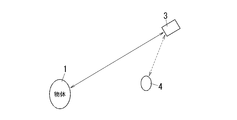
- the same technique can be adopted when a light receiving element having a single light receiving region is used as the light receiving unit 12. Further, even if the object is not the transparent object 2, as shown in FIG. 3, the non-target object is not included in the area (non-target area) between the space (target area) which is the detection target of the spatial information and the spatial information detection device 3. Even when a certain object 4 exists, erroneous detection of spatial information can be prevented by the following technique. In short, a non-target object such as the transparent object 2 or the object 4 exists in a region (non-target area) between the space (target area) that is a detection target of spatial information and the spatial information detection device 3. When the reflected light from the non-target object is incident on the spatial information detection device 3, erroneous detection can be prevented by the following technique.
- the transparent object 2 that causes false detection of the distance measuring device 3 (spatial information detecting device) is assumed to be a window plate or a partition plate, and the relative position between the distance measuring device and the transparent object when the distance measuring device is used. May be regarded as not changing. Therefore, if the position of the transparent object 2 is known with respect to the distance measuring device 3 and the component corresponding to the transparent object 2 can be removed from the charge generated in the distance measuring device 3, the effect of the transparent object 2 can be reduced. It can be removed.
- the correction information is generated from the information related to the spatial region (non-target area) where the transparent object 2 exists, and the correction information is given to the calculation unit 30, thereby correcting the distance value corrected with the correction information.
- the correction information is information related to the charges generated in the light receiving unit 12 due to light from the non-target area between the light projecting unit 11 and the light receiving unit 12 (that is, the spatial information detection device) and the target area. .
- the charge amount A0 is expressed by the relationship defined by the following equation (13). Is done.
- the charge amount gA0 corresponding to the charge amount A0 is expressed by the following formula ( 14).
- g is added as a prefix to indicate that the transparent object 2 exists. Therefore, gA means a component of signal light due to reflection from the transparent object 2 (a component caused by light from a non-target area in the signal light), and gB is a component of environmental light when only the transparent object 2 exists. And g ⁇ means a time difference due to reflection from the transparent object 2 (flight time with respect to the transparent object 2). That is, the component (non-target component) gA is the amount of non-target charge corresponding to the charge generated by the light receiving unit 12 due to light from the non-target space.
- the time difference g ⁇ is a time of flight (non-target time) from when the signal light is emitted from the light projecting unit 11 until the light-receiving unit 12 receives the signal light reflected by the non-target object (transparent object) 2 existing in the non-target area. Flight time).
- the non-target object is an object that causes light from the non-target area.
- the prefix g is added to indicate that the transparent object 2 exists.
- the charge amount bA0 to be obtained is an addition value of both (A0, gA0), and is represented by the relationship defined by the following equation (15).
- the charge amounts bA1, bA2, and bA3 corresponding to the charge amounts A1 to A3 are expressed by relationships defined by the following equations (16), (17), and (18), respectively.
- (bA0-bA2) and (bA1-bA3) are obtained by the distance measuring device 3 based on the amount of received light, so that the unknown value is the signal light included in the reflected light of the transparent object 2.
- BA3, (A0-A2), (A1-A3) can be calculated.
- the signal light component gA and the time difference g ⁇ obtained for the transparent object 2 are correction information. Further, the above formula is generated by reflection on the object 1 by removing the charge generated by the presence of the transparent object 2 from the charge (the amount of received light bA0, bA1, bA2, bA3) accumulated by the charge accumulating unit of the distance measuring device 3. In other words, the received charges (light reception amounts A0, A1, A2, A3) are obtained.
- the charge generated by the presence of the transparent object 2 is assumed to increase mainly due to reflection by the transparent object 2, but may include a charge that attenuates by passing through the transparent object 2.
- a technique for obtaining the signal light component gA and the time difference g ⁇ as correction information will be described.
- a rectangular wave signal having a binary signal value is used as a modulation signal for modulating signal light, and the duration of each signal value of the rectangular wave signal is 1 chip length (unit period) Tc. It is an integer multiple and changes randomly. Therefore, as described above, there is an upper limit in the measurable range from the charge amounts A0 to A3 to the object 1. For example, when the 1-chip length Tc is 100 [ns], the measurable range is 0 to 15 [m] if the phase of the first demodulated signal matches the modulated signal.
- the first, second, third, and fourth demodulated signals in this case are hereinafter referred to as first, second, third, and fourth reference demodulated signals, respectively.
- the change in the amount of charge due to the influence of the transparent object 2 can be obtained. That is, when various shift times td for shifting the demodulated signal with respect to the reference demodulated signal are set and the charge amount for each shift time td is obtained, correction information for removing the influence of the transparent object 2 can be obtained. .
- the demodulated signal shifted in the time axis direction by the shift time td with respect to the reference demodulated signal is referred to as a search demodulated signal (search signal).
- a positive shift time td indicates that the search signal is delayed by the shift time td with respect to the reference demodulated signal. Further, the fact that the shift time td is negative indicates that the search signal is advanced by the shift time td with respect to the reference demodulated signal.
- the reference demodulation signal is generated based on the modulation signal, and the search demodulation signal is shifted in the time axis direction with respect to the reference demodulation signal. And is equivalent to the case where the modulation signal is shifted in the time axis direction. That is, the first reference demodulated signal is matched with the reference signal to generate the second, third, and fourth reference demodulated signals, and the modulated signal is shifted in the time axis direction with respect to the first reference demodulated signal. May be. However, in the case where the reference demodulated signal is shifted and the case where the modulation signal is shifted, the direction of the shift with respect to the time axis is reversed.
- the shift time td becomes ⁇ (Tc ⁇ g ⁇ ) or less
- the charge amount gA0 is only the ambient light component gB and becomes a constant value. From this, when the shift time td is changed and the charge amount gA0 corresponding to the shift time td is obtained, the time difference g ⁇ can be obtained from the shift time td when the charge amount gA0 no longer changes. That is, the distance to the transparent object 2 is measured.
- the charge amount gA0 when the charge amount gA0 is obtained for a plurality of shift times td in a range in which the charge amount gA0 changes with respect to the shift time td ( ⁇ (Tc ⁇ g ⁇ ) ⁇ td ⁇ 0), the charge amount gA0 with respect to the shift time td
- the signal light component gA is calculated from the rate of change and the known information (unit time Tc). That is, the signal light component gA and the time difference g ⁇ as correction information for the presence of the transparent object 2 are obtained.
- the correction information gA, g ⁇ is obtained, as described above, the correction information gA, g ⁇ is applied to the charge amounts bA0, bA1, bA2, bA3 obtained when the distance measuring device measures the distance to the object 1.
- the influence of the transparent object 2 can be removed. That is, using the relationship defined by the following equations (25) and (26), the influence of the transparent object 2 is removed from the charge amounts (bA0-bA2) and (bA1-bA3) obtained by the distance measuring device.
- the values of (A0-A2) and (A1-A3) can be obtained.
- FIG. 8 shows a case where correction information (gA, g ⁇ ) is applied
- FIG. 8 shows a comparative example where correction information (gA, g ⁇ ) is not applied
- ab represents the distance to the object 1 calculated when the transparent object 2 does not exist
- ex represents the distance to the object 1 calculated when the transparent object 2 exists.
- FIG. 8 shows that there is a large difference in the measured distance depending on the presence or absence of the transparent object 2
- FIG. 7 shows that the measured distance is not affected by the presence or absence of the transparent object 2. .
- the transparent object 2 has been described as the non-target object.
- the object 4 that is not the transparent object 2 is in the vicinity (non-target area) of the distance measurement device 3 (spatial information detection device).
- the influence by the presence or absence of the object 4 can be removed by the same principle. That is, when the non-target object 4 is present in the vicinity of the distance measuring device 3, the reflected light (secondary reflection component) scattered on the surface of the object 4 is reflected as in the case where the transparent object 2 is present.
- the incident light may enter the distance measuring device 3 and the amount of received light (charge amount) may increase as compared to when the object 4 is not present.
- the influence of the secondary reflection component increases as the distance from the distance measuring device 3 to the object 4 is shorter.
- the secondary reflected component by the object 4 differs from the reflected light component by the transparent object 2 in the path incident on the distance measuring device 3, but both components are added to the reflected light component from the object 1.
- the influence of the presence or absence of 4 can be handled in the same manner as the component of the reflected light from the transparent object 2. Therefore, the influence by the presence or absence of the object 4 can be removed by using the above-described principle.
- the spatial information detection apparatus includes a light projecting unit 11, a light receiving unit 12, a calculation unit 30, a code generator 31, a modulation signal generation unit 32, and a demodulation signal generation unit. 33 and a correction information providing unit 34. That is, in this embodiment, the correction information providing unit 34 is added to the basic configuration for generating the distance image.
- the correction information providing unit 34 provides the calculation unit 30 with the correction information gA and g ⁇ used when calculating the distance value (spatial information).
- the correction information provider 34 not only provides the calculator 30 with the correction information gA and g ⁇ , but also has a function of obtaining the correction information gA and g ⁇ . That is, the correction information providing unit 34 generates correction information related to charges generated in the light receiving unit 12 due to light from the non-target area between the light projecting unit 11 and the light receiving unit 12 and the target area, and performs correction.
- the information is configured to be output to the arithmetic unit 30.
- the calculation unit 30 removes the influence of the transparent object 2 from the charge amounts (bA0-bA2) and (bA1-bA3) as described in principle by receiving the correction information gA and g ⁇ from the correction information providing unit 34. Thus, the values of (A0-A2) and (A1-A3) are obtained. That is, the calculation unit 30 calculates the spatial information by using the correction information gA and g ⁇ to remove the charge generated by reflection by the transparent object 2 from the charge accumulated by the charge accumulation unit. In other words, the arithmetic unit 30 uses the correction information to calculate the amount of signal charge (bA0-bA2, bA1-bA3) corresponding to the charge generated by the light receiving unit 12 due to the light from the target area. It is configured to correct the charge amount (A0-A2, A1-A3) and generate spatial information (distance L) based on the target charge amount.
- the relative phase (shift time td) between the modulation signal and the search demodulation signal is changed variously, and the relationship between the shift time td and the charge amount bA0 is changed. Need to ask.
- the shift time td is changed in units shorter than one chip length Tc.
- the correction information gA, g ⁇ needs to be calculated in advance before measuring the distance to the object 1. Therefore, it is necessary to perform an operation for obtaining correction information gA and g ⁇ related to the transparent object 2 separately from the operation of measuring the distance to the object 1.
- the correction information providing unit 34 performs an operation for obtaining the correction information gA and g ⁇ at an appropriate timing. For example, the correction information providing unit 34 may acquire the correction information gA and g ⁇ periodically at a predetermined timing. Further, the presence or absence of the object 1 in the space (target area) that is the detection target of the spatial information may be detected, and the correction information gA and g ⁇ may be acquired when it is determined that the object 1 does not exist. In order to determine whether or not the object 1 exists, for example, spatial information (an image or the like) obtained in a state where the object 1 does not exist may be stored and compared with the stored spatial information every time the spatial information is acquired. . That is, the correction information providing unit 34 determines that the object 1 does not exist every time the spatial information is acquired when there is no substantial difference in the spatial information.
- spatial information an image or the like
- the shift time td corresponds to the relative phase (shift time td) between the modulation signal and the search demodulation signal.
- the correction information providing unit 34 includes a phase variable unit 341 in order to obtain the correction information gA and g ⁇ by changing the phase (shift time td).
- the demodulated signal generation unit 33 functions as a search signal generation unit that generates a search signal (search demodulation signal) and outputs the search signal to the light receiving unit 12.
- the search signal is a signal having a predetermined time difference (shift time td) with respect to the modulation signal.
- the light receiving unit (photoelectric conversion unit) 12 is configured to generate a charge corresponding to the intensity of light received from the space during an integration period (second integration period) defined by a period in which the search signal is at a high level. Is done.
- the light receiving unit (charge storage unit) 12 generates charges generated during the integration period (second integration period) over a predetermined storage period (second storage period) longer than the integration period (second integration period).
- the accumulated charge is configured to be output to the correction information providing unit 34 as a corrected charge.
- the second integration period may be defined as a period in which the search signal is at a low level.
- the light receiving unit 12 increases the intensity of light received from the space during the second integration period defined by one of the first period when the search signal is high level and the second period when the search signal is low level. A corresponding charge may be generated.
- the phase variable unit 341 has a time difference (shift time) within a predetermined time range (search range) so that the demodulated signal generation unit (search signal generation unit) 33 generates a plurality of search signals having different time differences (shift time td). td) is changed with a change width smaller than the unit period (one chip length Tc).
- the phase variable unit 341 has a function of shifting the reference signal generated by the code generator 31 in the time axis direction (that is, shifting the phase).
- the shift time td is changed not in units of one chip length Tc but in units shorter than one chip length Tc.
- the range (search range) in which the shift time td is changed by the phase variable unit 341 is set by the range setting unit 343. That is, the range setting unit 343 has a function of setting a range in which the shift time td is changed to a range in which correction information regarding the transparent object 2 is acquired. In other words, the range setting unit 343 of the present embodiment specifies the search range of the phase variable unit 341.
- the range setting unit 343 includes a configuration for manually setting the range and a configuration for automatically setting the range as described later.
- the range setting unit 343 instructs the phase variable unit 341 to detect the shift time td from the set distance so as to detect correction information related to the transparent object 2 before and after the distance. That is, the range setting unit 343 determines a time range (search range) based on the set distance.
- the correction information providing unit 34 includes a correction information calculating unit 342 that calculates correction information gA and g ⁇ .
- the correction information calculation unit 342 acquires correction charge from the light receiving unit 12 for each search signal having a different time difference (shift time td), and generates correction information based on the relationship between the time difference (shift time td) and the amount of correction charge. Configured to do.
- correction information calculation unit 342 shifts with the charge amount (correction charge amount) gA0 (other charge amounts gA1, gA2, and gA3 may be used) accumulated by the charge accumulation unit 123 as described in principle.
- Correction information gA, g ⁇ is calculated using the relationship with time td.
- the correction information calculation unit 342 in the correction information providing unit 34 is transparent using the relationship between the phase (shift time td) changed by the phase variable unit 341 and the charge amount (correction charge amount) gA0 for each phase. Correction information gA and g ⁇ regarding the object 2 are calculated.
- the correction information providing unit 34 includes a correction information holding unit 344 that stores the correction information gA and g ⁇ calculated by the correction information calculation unit 342.
- the correction information gA and g ⁇ calculated in advance by the correction information calculation unit 342 and stored in the correction information holding unit 344 are employed, and the relationship described as the principle.
- the correction information gA, g ⁇ is applied to the equation to determine the distance. That is, the calculation unit 30 calculates the spatial information using the correction information gA and g ⁇ stored in the correction information holding unit 344. Since the correction information gA and g ⁇ is applied when generating the distance image in this way, the distance image from which the influence of the transparent object 2 is removed can be generated.
- the correction information gA and g ⁇ may change due to dirt adhering to the transparent object 2, scratches on the transparent object 2, temperature change, and the like. Therefore, it is desirable to update the correction information in a timely manner. For this reason, the correction information providing unit 34 instructs to update the correction information gA and g ⁇ stored in the correction information holding unit 344 (to the correction information calculation unit 342) when a predetermined update condition is satisfied. Part 345. That is, the correction information providing unit 34 is configured to determine whether or not a predetermined update condition is satisfied, and update the correction information when it is determined that the update condition is satisfied.
- the update condition determined by the update determination unit 345 for example, a predetermined update time is used. That is, the correction information gA and g ⁇ may be updated at regular intervals, or the time for updating the correction information gA and g ⁇ may be designated in advance.
- the spatial information corresponding to the transmittance of the medium is acquired using the reflection intensity image described above, and the correction information gA and g ⁇ is updated under the condition that the transmittance falls below a predetermined value with respect to the initial value. May be.
- the spatial information detection apparatus performs processing for generating spatial information (spatial information creation processing) and processing for generating correction information (correction information generation processing).
- the correction information generation process is executed before the spatial information generation process.
- the range setting unit 343 sets a search range.
- the search range is set to ⁇ tb ⁇ td ⁇ 0.
- the phase variable unit 341 selects a time difference (shift time td) within the search range set by the range setting unit 343. For example, the phase variable unit 341 selects 0 as the shift time td.
- the search signal generation unit (demodulation signal generation unit) 33 generates a search signal having the shift time td specified by the phase variable unit 341 and outputs the search signal to the light receiving unit 12.
- the search signal is generated with reference to the first demodulated signal.
- the modulation signal generation unit 32 outputs the modulation signal to the light projecting unit 11, and the search signal generation unit 33 outputs the search signal to the light receiving unit 12.
- the light projecting unit 11 When receiving the modulation signal, the light projecting unit 11 radiates signal light, which is light modulated by the received modulation signal, to a space including the target area.
- the light receiving unit 12 Upon receiving the search signal, the light receiving unit 12 uses the period in which the received search signal is at a high level as the integration period (second integration period), and charges from the space over the accumulation period (second accumulation period). accumulate. The light receiving unit 12 outputs the charge accumulated according to the received search signal to the correction information calculation unit 342 as a correction charge.
- the phase variable unit 341 changes the time difference (shift time td) within the search range with a change width smaller than the unit period (1 chip length Tc). For example, the phase variable unit 341 selects ta as the shift time td.
- phase variable unit 341 Every time the phase variable unit 341 selects the shift time td, a correction charge corresponding to the search signal having the shift time td selected by the phase variable unit 341 is obtained.
- the correction information calculation unit 342 obtains correction information (gA, g ⁇ ) based on the amount of correction charge for each search signal having a different shift time td (corresponding to the charge amount gA0 in this example). For example, the correction information calculation unit 342 checks the relationship between the shift time td and the correction charge amount gA0 (see FIG. 6).
- the correction information calculation unit 342 obtains the shift time td when the change rate of the correction charge amount gA0 with respect to the shift time td changes to zero.
- the shift time td when the rate of change of the correction charge amount gA0 with respect to the shift time td changes to 0 is the time difference g ⁇ .
- the rate of change is not strictly 0, but may be a value that can be regarded as 0 (that is, the correction charge amount gA0 is constant).
- the correction information calculation unit 342 calculates a product of the calculated rate of change (gA / Tc) and unit period (Tc). This product is the non-target charge amount gA corresponding to the light from the non-target area.
- the correction information calculation unit 342 stores the correction information gA and g ⁇ in the correction information holding unit 344.
- the spatial information detection apparatus executes the correction information generation process to generate correction information (gA, g ⁇ ).
- the spatial information detection device of the present embodiment executes a spatial information generation process.
- the demodulated signal generation unit 33 generates the first to fourth demodulated signals instead of the search signal (see FIGS. 4C to 4F).
- the modulation signal generation unit 32 outputs the modulation signal to the light projecting unit 11, and the demodulation signal generation unit 33 outputs the first to fourth demodulation signals to the light receiving unit 12.
- the light projecting unit 11 When receiving the modulation signal, the light projecting unit 11 radiates signal light, which is light modulated by the received modulation signal, to a space including the target area.
- the light receiving unit 12 When the light receiving unit 12 receives the demodulated signal, the light receiving unit 12 accumulates electric charges from the space over the accumulation period using the period during which the received demodulated signal is at the high level as the accumulation period. The light receiving unit 12 outputs the charge accumulated according to the received demodulated signal as a signal charge to the calculation unit 30.
- the arithmetic unit 30 obtains signal charges (signal charge amounts bA0, bA1, bA2, bA3) individually corresponding to the first to fourth demodulated signals.
- the calculation unit 30 acquires correction information (gA, g ⁇ ) from the correction information holding unit 344.
- the calculation unit 30 substitutes the signal charge amounts bA0, bA1, bA2, bA3, correction information gA, g ⁇ , and one chip length Tc into the following equation (27) to obtain the flight time ⁇ .
- the calculating part 30 calculates
- the calculation unit 30 uses the correction information (gA, g ⁇ ) to generate signal charge amounts (charge amounts bA0, bA1, bA2, bA3) by the light receiving unit 12 due to light from the target area. To the amount (A0, A1, A2, A3) of the target charge corresponding to the charge. The computing unit 30 generates spatial information (distance L) based on the amount of the target charge.
- the spatial information detection apparatus of the present embodiment includes the light projecting unit 11, the light receiving unit 12, the charge storage unit 123, the modulation signal generation unit 32, the demodulation signal generation unit 33, and the calculation unit 30.
- the correction information providing unit 34 is provided.
- the light projecting unit 11 is configured to project light into a space (target area) to be detected.
- the light receiving unit 12 is configured to receive light from the space and generate a charge corresponding to the amount of light received.
- the charge storage unit 123 is configured to store the charge generated by the light receiving unit 12 during a specified integration period over a predetermined storage period longer than the integration period.
- the modulation signal generation unit 32 is configured to generate a modulation signal, modulate the light output of the light projecting unit 11 with the modulation signal, and project the signal light.
- the modulation signal is a rectangular wave signal in which the duration of each binary signal value is an integral multiple of the unit period, and the duration varies randomly in the accumulation period.
- the demodulated signal generation unit 33 is configured to generate a demodulated signal having a predetermined phase with respect to the modulated signal and to specify the integration period using the demodulated signal.
- the calculation unit 30 is configured to calculate space information regarding the space from the charges accumulated by the charge accumulation unit 123.
- the correction information providing unit 34 The correction information related to the charge caused by the presence is given to the calculation unit 30 so that the spatial information is calculated by removing the influence of the charge caused by the presence of the non-target object from the charge accumulated by the charge accumulation unit 123.
- the spatial information detection apparatus includes the light projecting unit 11, the light receiving unit 12, the modulation signal generation unit 32, the demodulation signal generation unit 33, the calculation unit 30, and the correction information hand chest unit 34.
- the modulation signal generation unit 32 is configured to generate a modulation signal and output it to the light projecting unit 11.
- the modulation signal is a square wave signal in which the length of the high-level period and the low-level period is randomly determined from a length that is an integral multiple of a predetermined unit period.
- the light projecting unit 11 is configured to emit signal light to a space including a predetermined target area.
- the light projecting unit 11 is configured to generate signal light by modulating light with the modulation signal when receiving the modulation signal.
- the demodulated signal generation unit 33 is configured to generate a demodulated signal and output it to the light receiving unit 12.
- the demodulated signal is a signal having the same waveform as the modulated signal or the inverted modulated signal.
- the light receiving unit 12 is configured to receive light from the space.
- the light receiving unit 12 is charged according to the intensity of light received from the space during the integration period defined by one of the first period in which the demodulated signal is at a high level and the second period in which the demodulated signal is at a low level. Is configured to generate
- the light receiving unit 12 is configured to accumulate a charge generated during the integration period over a predetermined accumulation period longer than the integration period to generate a signal charge.
- the correction information providing unit 34 is configured to generate correction information related to charges generated in the light receiving unit 12 due to light from the non-target area between the light projecting unit 11 and the light receiving unit 12 and the target area.
- the computing unit 30 is configured to generate spatial information regarding the target area.
- the calculation unit 30 corrects signal charges (signal charge amounts bA0, bA1, bA2, and bA3) using correction information (gA, g ⁇ ) and is generated by the light receiving unit 12 due to light from the target area.
- the amount of the target charge (A0, A1, A2, A3) corresponding to the charge is determined.
- the computing unit 30 is configured to generate spatial information (distance L) based on the amount of target charges (A0, A1, A2, A3).
- the correction information providing unit 34 relatively changes the phase of the modulated signal and the demodulated signal in units shorter than the unit period (one chip length Tc).
- a correction information calculation unit 342 that calculates correction information related to the non-target object using the relationship between the phase changed by the phase variable unit 341 and the charge accumulated by the charge accumulation unit 123 for each phase.
- the spatial information detection device of this embodiment includes a search signal generation unit (demodulation signal generation unit) 33.
- the search signal generation unit 33 is configured to generate a search signal and output it to the light receiving unit 12.
- the search signal is a signal having a predetermined time difference with respect to the modulation signal.
- the correction information providing unit 34 includes a phase variable unit 341 and a correction information calculation unit 342.
- the light receiving unit 12 responds to the intensity of light received from the space during the second integration period defined in one of the first period in which the search signal is high level and the second period in which the search signal is low level. Configured to generate a charge.
- the light receiving unit 12 is configured to accumulate the charge generated during the second integration period over a predetermined second accumulation period longer than the second integration period to generate a correction charge.
- the phase variable unit 341 includes a time difference (shift time) within a predetermined time range (search range) so that the search signal generation unit (demodulation signal generation unit) 33 generates a plurality of search signals having different time differences (shift time td). td) is changed with a change width smaller than the unit period (one chip length Tc).
- the correction information calculation unit 342 acquires correction charge from the light receiving unit 12 for each search signal having a different time difference (shift time td), and generates correction information based on the relationship between the time difference (shift time td) and the amount of correction charge. Configured to do.
- the correction information providing unit 34 is stored in the correction information holding unit 344 that stores correction information and the correction information holding unit 344 when a predetermined update condition is satisfied.
- An update determination unit 345 that instructs to update the correction information.
- the correction information providing unit 34 is configured to determine whether or not a predetermined update condition is satisfied, and update the correction information when it is determined that the update condition is satisfied.
- the spatial information detection apparatus of the present embodiment described above even when a non-target object exists between a space (target area) as a detection target of spatial information, the correction related to the non-target object is performed. Since the spatial information is corrected using the information, there is an advantage that the influence of the non-target object is removed and the detection accuracy of the spatial information is improved.
- the correction information providing unit 34 calculates a component gA and a time difference g ⁇ as correction information.
- the component gA is the amount of non-target charge corresponding to the charge generated by the light receiving unit 12 due to light from the non-target space.
- the time difference g ⁇ is the time required for the light receiving unit 12 to receive the signal light reflected by the non-target object (the object causing the light from the non-target area) after the signal light is emitted from the light projecting unit 11 (ie, the time difference g ⁇ ). Time of flight for non-target objects).
- the correction information providing unit 34 obtains the component gA and the time difference g ⁇ based on the relationship between the shift time td and the correction charge amount gA0.
- the time difference g ⁇ is defined as the shift time td when the change rate of the correction charge amount gA0 with respect to the shift time td changes to zero. Therefore, the correction information providing unit 34 obtains the shift time td when the change rate of the correction charge amount gA0 with respect to the shift time td changes to 0 as the time difference g ⁇ .
- the computing unit 30 uses the component gA and the time difference g ⁇ to convert the signal charge amount (bA0, bA1, bA2, bA3) into the target charge amount (A0, A1, A2, A3) (the above equation (15 ) To (20) and (25) to (27)) are stored in advance.
- the computing unit 30 corrects the amount of signal charge to the amount of target charge using the component gA obtained from the correction information providing unit 34, the time difference g ⁇ , and a conversion formula.
- the correction information providing unit 34 may determine whether or not a non-target object (for example, the transparent object 2) exists in the non-target area. That is, if the correction information providing unit 34 determines that there is no non-target object, the correction information providing unit 34 does not calculate correction information. In this case, the calculation unit 30 obtains spatial information from the amount of signal charge. On the other hand, if the correction information providing unit 34 determines that a non-target object exists, it calculates correction information. In this case, the arithmetic unit 30 corrects the amount of signal charge to the amount of target charge using the correction information, and obtains spatial information from the amount of target charge.
- a non-target object for example, the transparent object 2
- the spatial information is the distance (L) to the object (object) 1 existing in the target area.
- the calculation unit 30 calculates the flight time ⁇ required for the light receiving unit 12 to receive the signal light reflected from the object (object) 1 after the signal light is radiated from the light projecting unit 11 and the amount of target charge (for example, charge It is calculated from the quantities A0, A1, A2, A3).
- the computing unit 30 is configured to obtain the distance L based on the flight time ⁇ .
- the correction information includes a non-target component gA and a non-target flight time g ⁇ .
- the non-target component gA is the amount of non-target charge corresponding to the charge generated by the light receiving unit 12 due to light from the non-target area.
- the non-target flight time g ⁇ is the time required for the light receiving unit 12 to receive the signal light reflected by the non-target object existing in the non-target area after the signal light is emitted from the light projecting unit 11.
- the correction information calculation unit 342 is configured to calculate the rate of change of the correction charge amount gA0 with respect to the time difference (shift time) td.
- the correction information calculation unit 342 does not calculate the product of the rate of change (gA / Tc) and the unit period (Tc) in the range in which the correction charge amount gA0 linearly changes with respect to the time difference (shift time) td. It is comprised so that it may obtain
- the correction information calculation unit 342 is configured to obtain the time difference (shift time) td when the change rate changes to 0 as the non-target flight time g ⁇ .
- the calculation unit 30 uses the non-target component gA and the non-target flight time g ⁇ to convert the signal charge amount (bA0, bA1, bA2, bA3) into the target charge amount (A0, A1, A2, A3).
- the calculation unit 30 is configured to correct the amount of signal charge to the amount of target charge using the non-target component gA and the non-target flight time g ⁇ obtained from the correction information providing unit 34 and the conversion formula.
- the calculation unit 30 performs conversion for directly obtaining the flight time ⁇ from the non-target component gA, the non-target flight time g ⁇ , and the signal charge amount (bA0, bA1, bA2, bA3).
- a formula (for example, the above formula (27)) is stored.
- the demodulated signal generation unit 33 is configured to generate a plurality of demodulated signals.
- the plurality of demodulated signals include a first demodulated signal having the same waveform as the modulated signal, a second demodulated signal obtained by inverting the first demodulated signal, and a unit period (one chip) from the first demodulated signal.
- Length Tc) includes two of a delayed third demodulated signal and a fourth demodulated signal which is a signal obtained by inverting the third demodulated signal.
- the demodulated signal generation unit 33 first inverts the first demodulated signal having the same binary relationship as the modulated signal and the binary of the first demodulated signal. 2 demodulated signals, a third demodulated signal obtained by delaying the modulated signal by a unit period, and a fourth demodulated signal obtained by inverting the binary value of the third demodulated signal. Is generated.
- the arithmetic unit 30 receives light from the light projection calculated by applying the correction information to the charge amount generated during the integration period specified by each demodulated signal generated by the demodulated signal generation unit 33 and accumulated during the accumulation period.
- the distance L to the object existing in the space is obtained as spatial information using the time difference until (the flight time ⁇ ).
- the charge amount A0 corresponding to the reflected light from the object 1 and the charge amount gA0 corresponding to the reflected light from the transparent object 2 are shifted by the shift time. It changes as shown in FIG. 9A with respect to the change of td.
- ob corresponds to the object 1
- fn corresponds to the transparent object 2. That is, when the ranges that change according to the change of the shift time td are compared, the range (effective range) corresponding to the charge amount A0 corresponding to the reflected light from the object 1 is the charge corresponding to the reflected light from the transparent object 2. It becomes narrower than the range corresponding to the quantity gA0.
- FIG. 9 (a) for the sake of simplicity, the maximum values of the signal light components and the ambient light components of the charge amount A0 and the charge amount gA0 are shown to be equal. There are many. However, since the information of interest is a boundary point between a region that changes in accordance with the change in the shift time td and a region in which the change does not occur, the size of the component does not need to be considered.
- the reflected light detected by the distance measuring device the reflected light from the object 1 and the reflected light from the transparent object 2 are combined, so the actually detected charge amount bA0 is as shown in FIG. 9B.
- the charge amount bA0 is constant regardless of the change in the shift time td, and the charge amount bA0 changes according to the change in the shift time td. It is considered that the boundary point Pb1 with the region is caused by the transparent object 2. That is, in FIG. 9B, the region between the first bending point Pb1 and the second bending point Pb2 from the left is a change in the amount of received light gA0 obtained by the reflected light from the transparent object 2 only. It can be judged that there is.
- correction information gA and g ⁇ regarding the transparent object 2 can be obtained by the following procedure. First, after determining the change of the charge amount bA0 according to the change of the shift time td, the shift time of the boundary point where the charge amount bA0 is constant regardless of the change of the shift time td is determined. This boundary point becomes the first bending point Pb1. Next, the rate of change of the charge amount bA0 with respect to the shift time td is obtained on the side shorter than the shift time of the boundary point, and the point at which the rate of change changes to a specified value or more is obtained. This point becomes the second bending point Pb2.
- the rate of change in the region between the two bending points Pb1 and Pb2 can be expressed by the charge amount gA0 obtained only by the reflected light from the transparent object 2. It can be regarded as the rate of change. Therefore, if a range for changing the shift time td is set based on this region, information necessary for obtaining the correction information gA and g ⁇ related to the transparent object 2 can be obtained. That is, by giving the shift time td corresponding to the bending points Pb1 and Pb2 to the range setting unit 343, the change range of the shift time td necessary for calculating the correction information gA and g ⁇ is automatically determined.
- a correction information acquisition unit 346 is added to the correction information providing unit 34 shown in FIG.
- the correction information acquisition unit 346 has a search mode for automatically obtaining the bending points Pb1 and Pb2, and a setting mode for automatically determining a range in which the shift time td is changed from the bending points Pb1 and Pb2 obtained in the search mode.
- the correction information acquisition unit 346 obtains the bending points Pb1 and Pb2 described above by setting a plurality of types of phases in the phase variable unit 341, respectively.
- the correction information acquisition unit 346 based on the relationship between the time difference (shift time td) and the correction charge amount (bA0), shift time td at the boundary point where the charge amount bA0 is constant regardless of the change in the shift time td.
- the boundary point is a point where the change rate of the charge amount bA0 with respect to the shift time td is zero in the correction information acquisition unit 346.
- the correction information acquisition unit 346 obtains the rate of change in the amount of correction charge with respect to the time difference (shift time td).
- the correction information acquisition unit 346 detects the boundary point based on the relationship between the change rate (gA / td) and the time difference (td).
- the boundary point is, for example, the bending point Pb1 in FIG.
- the bending point Pb1 defines the lower limit of the effective range.
- the correction information acquisition unit 346 obtains a change point at which the rate of change of the charge amount bA0 with respect to the shift time td changes to a specified value or more in a range where the shift time td is larger than the shift time td corresponding to the boundary point.
- the change point is, for example, the bending point Pb2 in FIG.
- the bending point Pb2 defines the upper limit of the effective range.
- the prescribed value is set to such a size that if the rate of change is less than the prescribed value, it can be assumed that the rate of change is constant (the slope is constant) in the effective range.
- the correction information acquisition part 36 calculates
- the range setting unit 343 calculates the correction information gA and g ⁇ by changing the shift time td within a range necessary for calculating the correction information gA and g ⁇ .
- the correction information providing unit 34 determines the range in which the phase variable unit 341 changes the phase (search range) by the charge accumulated in the charge accumulation unit 123 due to light from the space.
- a range including the generated charge (a range on the right side of the bending point Pb2 in FIG. 9B) and a range not including the charge generated by the light from the space (a range on the left side of the bending point Pb2 in FIG. 9B) ) Is provided with a range setting unit 343 that limits and sets a range smaller than the phase (shift time td) corresponding to the boundary point (bending point Pb2).
- the correction information providing unit 34 specifies a valid range of a time difference (shift time td) in which correction charges not including the target charges (A0, A1, A2, A4) are obtained from the light receiving unit 12. Is provided.
- the correction information calculation unit 342 generates correction information based on the relationship between the time difference (shift time td) within the effective range specified by the range setting unit 343 and the amount of correction charge (gA0, gA1, gA2, gA3). Configured as follows.
- the range setting unit 343 changes the phase (shift time td) in the phase variable unit 341 as time passes, and the changed phase and the amount of light received by the light receiving unit 12 for each phase.
- a phase range effective range in which charges are generated by reflection only by the non-target object is automatically obtained.
- the correction information providing unit 34 determines the effective range based on the relationship between the time difference (shift time td) within the predetermined time range (search range) and the amount of correction charge (gA0, gA1, gA2, gA3).
- a correction information acquisition unit 346 for determination is provided.
- the range setting unit 343 is configured to specify the effective range determined by the correction information acquisition unit 346.
- one kind of charge amount in the above-described example, the charge amount corresponding to the integration period specified by the first demodulated signal
- the difference between the minimum value and the maximum value of the charge amount is the charge amount gA and the charge amount gA with respect to the reflected light from the transparent object 2
- the change in the charge amount gA with respect to the change in the shift time td is relatively small.
- the charge amount A0 corresponding to the integration period specified by the first demodulated signal and the charge amount A2 corresponding to the integration period specified by the third demodulated signal are in a contradictory relationship, and the change in the shift time td
- the other changes in a decreasing direction. That is, if the difference (gA0 ⁇ gA2) between the two charge amounts gA0 and gA2 is used, the change in the charge amount (gA0 ⁇ gA2) with respect to the shift time td is doubled.
- the correction information providing unit 34 uses the charge amount (gA0-gA2) instead of using the charge amount gA0, so that the signal light component (from the non-target space) due to reflection on the transparent object 2 is used. It is preferable to obtain correction information gA and g ⁇ as non-target charge amounts gA and time differences g ⁇ corresponding to the charges generated by the light receiving unit 12 due to light. By obtaining the correction information gA and g ⁇ from the charge amount (gA0-gA2), the accuracy of the correction information gA and g ⁇ can be improved as compared with the case of obtaining the correction information gA and g ⁇ from the charge amount gA0.
- the following expression (28) is established in the light projection period for the object 1 that exists in the range where the time difference ⁇ satisfies 0 ⁇ ⁇ ⁇ Tc.
- the suffix “L” is added to the charge amount in the light projection period, and the suffix “D” is added to the charge amount in the non-light projection period.
- the received light amount bA0 (bA0L) in the light projection period is expressed by the following equation (30).
- the signal light component A (that is, the reflection intensity value) is obtained using the charge amounts bA0 and bA1.
- the similar operation can be performed not by a combination of the charge amounts bA0 and bA1, but by a combination of any one of the charge amounts bA0 and bA2 and any one of the charge amounts bA1 and bA3.
- the correction information providing unit 34 obtains the amount of charge gA caused by the light from the non-target area (the reflected light from the non-target object) as the correction information.
- the demodulated signal generating unit 33 generates two demodulated signals (hereinafter referred to as “first timing signal” and “second timing signal”) having different time differences from the modulated signal, and outputs them to the light receiving unit 12.
- the calculation unit 30 includes a charge amount (first charge amount, for example, bA0L) corresponding to the first timing signal in the light projection period and a charge amount (second charge) corresponding to the first timing signal in the non-light projection period. And a difference value (first difference value, for example, bA0L ⁇ bA0D) between the first charge amount and the second charge amount is obtained.
- the calculation unit 30 has a charge amount (third charge amount, for example, bA1L) corresponding to the second timing signal in the light projection period, and a charge amount (first charge) corresponding to the fourth timing signal in the non-light projection period.
- charge amounts for example, bA1D
- second difference value for example, bA1L ⁇ bA1D
- the calculating unit 30 obtains the reflection intensity value (A) by subtracting the correction information (gA) from the sum of the first difference value and the second difference value. As described above, the calculation unit 30 obtains the reflection intensity (reflection intensity value A) based on the difference between the amount of the target charge corresponding to the light projection period and the amount of the target charge corresponding to the non-light projection period.
- the spatial information is the reflection intensity of the signal light in the target area.
- the correction information includes the non-target component gA.
- the non-target component gA is the amount of non-target charge corresponding to the charge generated by the light receiving unit 12 due to light from the non-target area.
- the correction information calculation unit 342 is configured to calculate the rate of change of the correction charge amount gA0 with respect to the time difference (shift time) td.
- the correction information calculation unit 342 does not calculate the product of the rate of change (gA / Tc) and the unit period (Tc) in the range in which the correction charge amount gA0 linearly changes with respect to the time difference (shift time) td. It is comprised so that it may obtain
- the arithmetic unit 30 uses the non-target component gA to convert the signal charge amount (bA0, bA1, bA2, bA3) into the target charge amount (A0, A1, A2, A3) (for example, the above formula (33 )) Is pre-stored.
- the computing unit 30 is configured to correct the amount of signal charge to the amount of target charge using the non-target component gA obtained from the correction information providing unit 34 and the conversion formula.
- the light projecting unit 11 is configured to emit signal light during the light projection period and not emit signal light during the non-light projection period.
- the computing unit 30 is configured to obtain the reflection intensity based on the difference between the amount of target charge corresponding to the light projection period and the amount of target charge corresponding to the non-light projection period.
- the spatial information detection device of this embodiment is used as an intensity detection device. That is, the modulation signal generating unit 32 provides a light projecting period during which signal light is projected from the light projecting unit 11 into the space and a non-light projecting period during which signal light from the light projecting unit 11 to the space is stopped.
- the calculation unit 30 uses the charge accumulated by the charge accumulation unit 123 during the light projection period (signal charge) and the charge accumulated by the charge accumulation unit 123 during the non-light projection period (signal charge). By removing the charge amount corresponding to the ambient light received by the light receiving unit 12 during the non-projection period from the charge amount received during the light period, and applying the correction information, the reflection intensity of the signal light is reduced. Obtained as spatial information.
- the reflection intensity value (A) is expressed by the following equation (37).
- the demodulated signal generation unit 33 As described above, in this modified example, the demodulated signal generation unit 33, as described above, the first demodulated signal, the second demodulated signal, the third demodulated signal, and the fourth demodulated signal, , Generate.
- the computing unit 30 converts the charge amount bA0 corresponding to the first demodulated signal, the charge amount bA1 corresponding to the second demodulated signal, the charge amount bA2 corresponding to the third demodulated signal, and the fourth demodulated signal.
- the corresponding charge amount bA3, correction information (gA), and the above equation (37) are substituted to obtain the reflection intensity value (A).
- the correction information gA is applied to the charge amounts bA0, bA1, bA2, and bA3 including the influence of the reflection from the transparent object 2, and the signal light component A (that is, the reflection intensity) Value). That is, the calculation unit 30 can remove the influence of the transparent object 2 on the reflection intensity value by performing a calculation using the above equation (37).
Abstract
Description
距離測定装置は、図1に示すように、検出対象となる空間に投光する投光部11と、当該空間から受光する受光部12とを備える。空間に物体(対象物)1が存在していると、投光部11から投光された光(以下、「信号光」という)は物体1で反射され、受光部12に物体1からの反射光が入射する。したがって、信号光を投光部11から投光してから受光部12で受光されるまでの時間(飛行時間)に相当する物理量を計測することにより、物体1までの距離が計測される。すなわち、図示する距離測定装置は、飛行時間法(タイムオブフライト法)の原理を用いて距離を測定する。
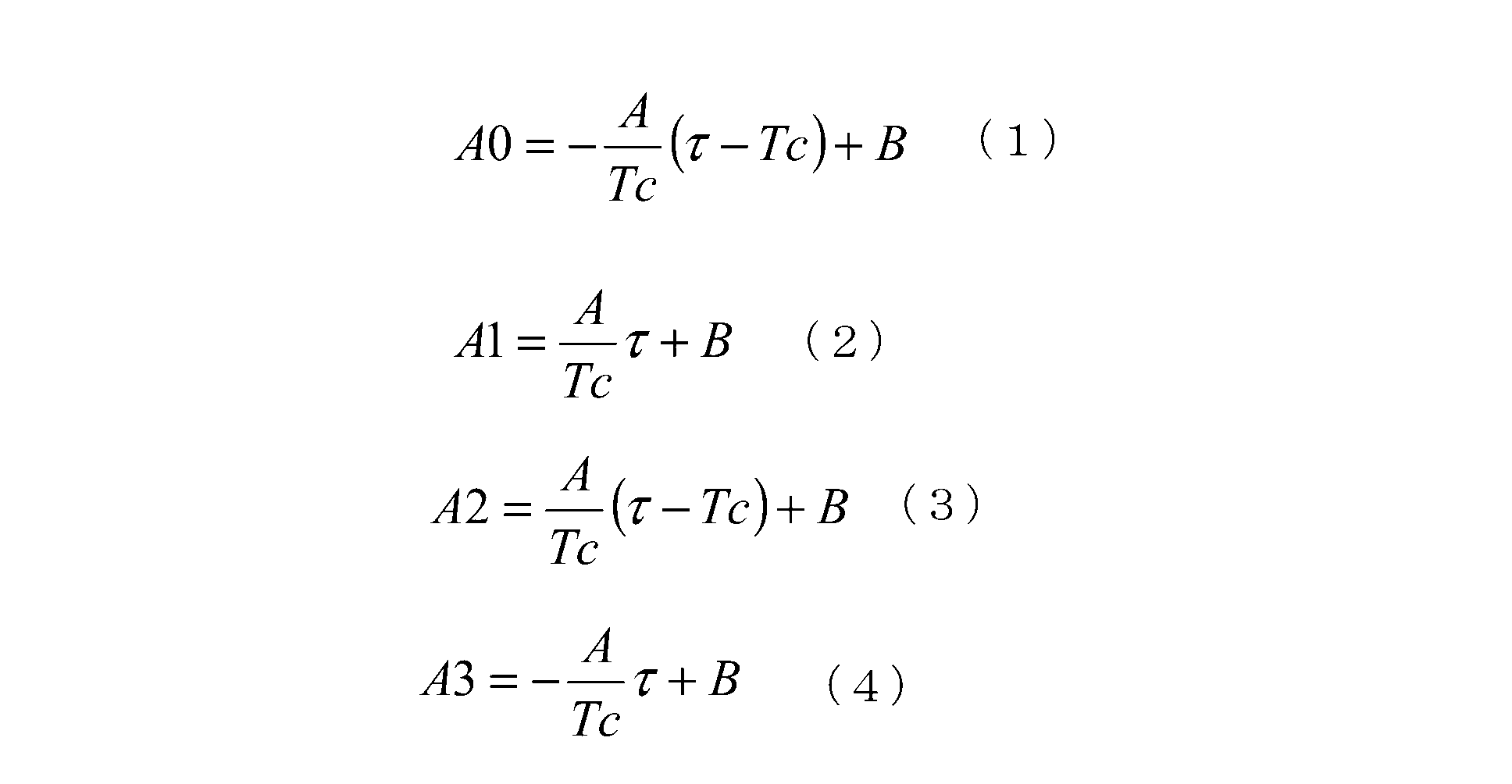


次に、物体1での反射光の強度を検出する強度検出装置について説明する。強度検出装置では、発光源111から空間に信号光を投光する投光期間と、発光源111から空間に信号光を投光しない非投光期間とを設け、投光期間に受光した光から非投光期間に検出される環境光の成分を除去することにより、反射光の強度を検出する。
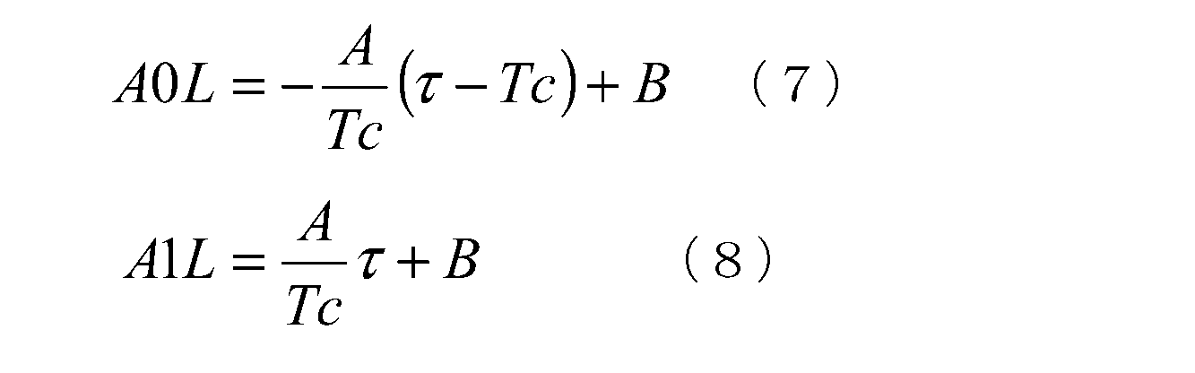


以下では、図2に示すように、空間情報検出装置3と検出対象となる空間(対象区域)との間に、非対象物体としてガラス板のような透明物体2が存在している場合に、空間情報の誤検出を防止する技術について説明する。透明物体2は、発光源111から投光する信号光が透過する物体を意味し、可視光は必ずしも透過しなくてもよい。また、空間情報検出装置3が、距離画像を生成する距離測定装置である場合を例にして説明するが、濃淡画像を生成する強度検出装置である場合も同様の技術を採用可能である。さらに、受光部12として単一の受光領域を備えた受光素子を用いる場合も同様の技術を採用可能である。また、透明物体2ではなくとも、図3のように、空間情報の検出対象である空間(対象区域)と空間情報検出装置3との間となる領域(非対象区域)に、非対象物体である物体4が存在する場合にも、以下の技術により空間情報の誤検出を防止することができる。要するに、空間情報の検出対象である空間(対象区域)と空間情報検出装置3との間となる領域(非対象区域)に、透明物体2や物体4のような非対象物体が存在することによって、非対象物体からの反射光が空間情報検出装置3に入射する場合には、以下の技術により誤検出を防止できる。
距離測定装置3(空間情報検出装置)の誤検出の原因になる透明物体2は、窓板や仕切板を想定しており、距離測定装置の使用時において距離測定装置と透明物体との相対位置が変化しないとみなしてよい。したがって、距離測定装置3に対して透明物体2の存在位置が既知であって、距離測定装置3において生成する電荷から透明物体2に相当する成分を除去することができれば、透明物体2の影響を除去することができると考えられる。


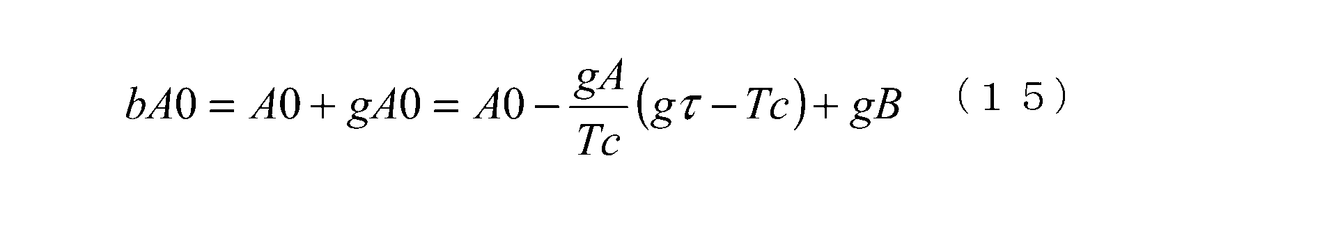


本実施形態の空間情報検出装置は、図1に示すように、投光部11と、受光部12と、演算部30と、コード発生器31と、変調信号生成部32と、復調信号発生部33と、補正情報提供部34と、を備える。すなわち、本実施形態は、距離画像を生成する基本の構成に対し、補正情報提供部34を付加している。

実施形態1では、透明物体2のみが存在する範囲において補正情報gA、gτを算出する技術を説明したが、補正情報gA、gτを算出する際に透明物体2のみが存在する状態とするのが困難な場合がある。そこで、距離測定装置に対して、距離の測定を行う空間よりも透明物体2との距離のほうが小さいことを利用して、透明物体2に関する補正情報gA、gτを取得する技術について説明する。
上述した各実施形態では、距離測定装置について透明物体2の存在下における動作を説明したが、強度検出装置を用いる場合でも、補正情報gA、gτを用いることにより、透明物体2の存在により生じた電荷を除いて空間情報を算出することができる。すなわち、本実施形態の空間情報検出装置は、強度検出装置として用いられる。


Claims (9)
- 所定の対象区域を含む空間に信号光を放射する投光部と、
前記空間からの光を受ける受光部と、
変調信号を生成して前記投光部に出力する変調信号生成部と、
復調信号を生成して前記受光部に出力する復調信号生成部と、
前記対象区域に関する空間情報を生成する演算部と、
補正情報提供部と、
を備え、
前記変調信号は、ハイレベルである期間とロウレベルである期間との長さが所定の単位期間の整数倍の長さから乱数的に決定された方形波信号であり、
前記投光部は、前記変調信号を受け取ると前記変調信号で光を変調して前記信号光を生成するように構成され、
前記復調信号は、前記変調信号または反転された前記変調信号と同じ波形を有する信号であり、
前記受光部は、前記復調信号がハイレベルである第1期間とロウレベルである第2期間とのいずれか一方の期間で定義される集積期間の間に前記空間から受け取った光の強度に応じた電荷を生成し、前記集積期間の間に生成された電荷を前記集積期間よりも長い所定の蓄積期間に亘って蓄積して信号電荷を生成するように構成され、
前記補正情報提供部は、前記投光部および前記受光部と前記対象区域との間の非対象区域からの光に起因して前記受光部で生成される電荷に関する補正情報を生成するように構成され、
前記演算部は、前記補正情報を利用して前記信号電荷の量を前記対象区域からの光に起因して前記受光部で生成される電荷に対応する対象電荷の量に補正し、前記対象電荷の量に基づいて前記空間情報を生成するように構成される
ことを特徴とする空間情報検出装置。 - 探索信号を生成して前記受光部に出力する探索信号生成部を備え、
前記探索信号は、前記変調信号に対して所定の時間差を有する信号であり、
前記補正情報提供部は、位相可変部と、補正情報算出部と、を備え、
前記受光部は、前記探索信号がハイレベルである第1期間とロウレベルである第2期間とのいずれか一方の期間で定義される第2集積期間の間に前記空間から受け取った光の強度に応じた電荷を生成し、前記第2集積期間の間に生成された電荷を前記第2集積期間よりも長い所定の第2蓄積期間に亘って蓄積して補正電荷を生成するように構成され、
前記位相可変部は、前記時間差が異なる複数の前記探索信号を前記探索信号生成部が生成するように、所定の時間範囲内において前記時間差を前記単位期間より小さい変化幅で変化させるように構成され、
前記補正情報算出部は、前記時間差が異なる前記探索信号毎に前記受光部から前記補正電荷を取得し、前記時間差と前記補正電荷の量との関係に基づいて前記補正情報を生成するように構成される
ことを特徴とする請求項1記載の空間情報検出装置。 - 前記空間情報は、前記対象区域に存在する対象物までの距離であり、
前記演算部は、前記信号光が前記投光部から放射されてから前記対象物で反射された前記信号光を前記受光部が受け取るまでにかかる飛行時間を前記対象電荷の量から算出し、前記飛行時間に基づいて前記距離を求めるように構成され、
前記補正情報は、非対象成分と、非対象飛行時間とを含み、
前記非対象成分は、前記非対象区域からの光に起因して前記受光部で生成された電荷に対応する非対象電荷の量であり、
前記非対象飛行時間は、前記信号光が前記投光部から放射されてから前記非対象区域に存在する非対象物体で反射された前記信号光を前記受光部が受け取るまでにかかる時間であり、
前記補正情報算出部は、前記時間差に対する前記補正電荷の量の変化率を算出するように構成され、
前記補正情報算出部は、前記時間差に対して前記補正電荷の量が直線的に変化する範囲における前記変化率と、前記単位期間と、の積を前記非対象成分として求めるように構成され、
前記補正情報算出部は、前記変化率が0に変わるときの前記時間差を前記非対象飛行時間として求めるように構成され、
前記演算部は、前記非対象成分および前記非対象飛行時間を用いて前記信号電荷の量を前記対象電荷の量に換算する換算式を、予め記憶するように構成され、
前記演算部は、前記補正情報提供部から得た前記非対象成分および前記非対象飛行時間と、前記換算式とを用いて、前記信号電荷の量を前記対象電荷の量に補正するように構成される
ことを特徴とする請求項2記載の空間情報検出装置。 - 前記復調信号生成部は、複数の前記復調信号を生成するように構成され、
前記複数の復調信号は、前記変調信号と同じ波形を有する第1の復調信号と、前記第1の復調信号を反転させた信号である第2の復調信号と、前記第1の復調信号から前記単位期間遅延する第3の復調信号と、前記第3の復調信号を反転させた信号である第4の復調信号とのうち2つを含む
ことを特徴とする請求項3記載の空間情報検出装置。 - 前記空間情報は、前記対象区域における前記信号光の反射強度であり、
前記補正情報は、非対象成分を含み、
前記非対象成分は、前記非対象区域からの光に起因して前記受光部で生成された電荷に対応する非対象電荷の量であり、
前記補正情報算出部は、前記時間差に対する前記補正電荷の量の変化率を求めるように構成され、
前記補正情報算出部は、前記時間差に対して前記補正電荷の量が直線的に変化する範囲における前記変化率と、前記単位期間との積を前記非対象成分として求めるように構成され、
前記演算部は、前記非対象成分を用いて前記信号電荷の量を前記対象電荷の量に換算する換算式を、予め記憶するように構成され、
前記演算部は、前記補正情報提供部から得た前記非対象成分と、前記換算式とを用いて、前記信号電荷の量を前記対象電荷の量に補正するように構成される
ことを特徴とする請求項2記載の空間情報検出装置。 - 前記投光部は、投光期間に前記信号光を放射し、非投光期間に前記信号光を放射しないように構成され、
前記演算部は、前記投光期間に対応する前記対象電荷の量と前記非投光期間に対応する前記対象電荷の量との差に基づいて前記反射強度を求めるように構成される
ことを特徴とする請求項5項記載の空間情報検出装置。 - 前記補正情報提供部は、前記対象電荷を含まない前記補正電荷が前記受光部から得られる前記時間差の有効範囲を指定する範囲設定部を備え、
前記補正情報算出部は、前記範囲設定部で指定された前記有効範囲内の前記時間差と前記補正電荷の量との関係に基づいて前記補正情報を生成するように構成される
ことを特徴とする請求項2~6のうちいずれか1項記載の空間情報検出装置。 - 前記補正情報提供部は、前記所定の時間範囲内の前記時間差と前記補正電荷の量との関係に基づいて前記有効範囲を決定する補正情報取得部を備え、
前記範囲設定部は、前記補正情報取得部で決定された前記有効範囲を指定するように構成される
ことを特徴とする請求項7記載の空間情報検出装置。 - 前記補正情報提供部は、所定の更新条件が満たされたかどうかを判定し、前記更新条件が満たされたと判定すると前記補正情報を更新するように構成される
ことを特徴とする請求項1~8のうちいずれか1項記載の空間情報検出装置。
Priority Applications (3)
| Application Number | Priority Date | Filing Date | Title |
|---|---|---|---|
| EP12749340.1A EP2680035A4 (en) | 2011-02-21 | 2012-02-21 | DEVICE FOR DETECTING SPATIAL INFORMATION |
| US13/985,935 US9030676B2 (en) | 2011-02-21 | 2012-02-21 | Spatial information detection device |
| JP2013501044A JP5655133B2 (ja) | 2011-02-21 | 2012-02-21 | 空間情報検出装置 |
Applications Claiming Priority (2)
| Application Number | Priority Date | Filing Date | Title |
|---|---|---|---|
| JP2011035030 | 2011-02-21 | ||
| JP2011-035030 | 2011-02-21 |
Publications (1)
| Publication Number | Publication Date |
|---|---|
| WO2012115083A1 true WO2012115083A1 (ja) | 2012-08-30 |
Family
ID=46720860
Family Applications (1)
| Application Number | Title | Priority Date | Filing Date |
|---|---|---|---|
| PCT/JP2012/054064 WO2012115083A1 (ja) | 2011-02-21 | 2012-02-21 | 空間情報検出装置 |
Country Status (5)
| Country | Link |
|---|---|
| US (1) | US9030676B2 (ja) |
| EP (1) | EP2680035A4 (ja) |
| JP (1) | JP5655133B2 (ja) |
| TW (1) | TWI442077B (ja) |
| WO (1) | WO2012115083A1 (ja) |
Cited By (7)
| Publication number | Priority date | Publication date | Assignee | Title |
|---|---|---|---|---|
| JP2014163717A (ja) * | 2013-02-22 | 2014-09-08 | Stanley Electric Co Ltd | 距離画像生成装置および距離画像生成方法 |
| CN105739584A (zh) * | 2014-08-20 | 2016-07-06 | 全视科技有限公司 | 用于飞行时间3d图像传感器的可编程电流源 |
| JPWO2015125478A1 (ja) * | 2014-02-24 | 2017-03-30 | 日本電気株式会社 | 物体検出装置、pos端末装置、物体検出方法及びコンピュータプログラム |
| WO2020026626A1 (ja) * | 2018-08-01 | 2020-02-06 | ソニーセミコンダクタソリューションズ株式会社 | 計測装置 |
| CN111033315A (zh) * | 2017-08-08 | 2020-04-17 | 国立大学法人静冈大学 | 距离图像测定装置以及距离图像测定方法 |
| JP2021526219A (ja) * | 2018-04-16 | 2021-09-30 | ▲寧▼波▲飛▼芯▲電▼子科技有限公司Ningbo Abax Sensing Co., Ltd. | 測距方法、装置、センサー及びセンサーアレイ |
| WO2022064605A1 (ja) * | 2020-09-24 | 2022-03-31 | 株式会社ソニー・インタラクティブエンタテインメント | 位置情報取得システム、位置情報取得方法、および位置情報取得装置 |
Families Citing this family (7)
| Publication number | Priority date | Publication date | Assignee | Title |
|---|---|---|---|---|
| US10324033B2 (en) * | 2012-07-20 | 2019-06-18 | Samsung Electronics Co., Ltd. | Image processing apparatus and method for correcting an error in depth |
| TWI564754B (zh) * | 2014-11-24 | 2017-01-01 | 圓剛科技股份有限公司 | 空間運動感測器與空間運動感測方法 |
| TWI625538B (zh) * | 2015-09-10 | 2018-06-01 | 義明科技股份有限公司 | 非接觸式光學感測裝置及感測三維空間之物件深度位置的方法 |
| CN106527761A (zh) | 2015-09-10 | 2017-03-22 | 义明科技股份有限公司 | 非接触式光学感测装置及三维空间物件深度位置感测方法 |
| US20210318443A1 (en) * | 2018-07-17 | 2021-10-14 | Sony Semiconductor Solutions Corporation | Electronic device and method |
| EP3715907B1 (en) * | 2019-03-27 | 2024-02-28 | Infineon Technologies AG | Methods and apparatuses for compensating light reflections from a cover of a time-of-flight camera |
| JP7348099B2 (ja) * | 2020-02-13 | 2023-09-20 | 株式会社アドバンテスト | 光学試験用装置 |
Citations (5)
| Publication number | Priority date | Publication date | Assignee | Title |
|---|---|---|---|---|
| JP2004045304A (ja) | 2002-07-15 | 2004-02-12 | Matsushita Electric Works Ltd | 撮像素子を用いた測距装置および測距方法 |
| JP2006121617A (ja) | 2004-10-25 | 2006-05-11 | Matsushita Electric Works Ltd | 空間情報の検出装置 |
| WO2010098454A1 (ja) * | 2009-02-27 | 2010-09-02 | パナソニック電工株式会社 | 距離測定装置 |
| JP2011022089A (ja) * | 2009-07-17 | 2011-02-03 | Panasonic Electric Works Co Ltd | 空間情報検出装置 |
| JP2011022088A (ja) * | 2009-07-17 | 2011-02-03 | Panasonic Electric Works Co Ltd | 空間情報検出装置 |
Family Cites Families (4)
| Publication number | Priority date | Publication date | Assignee | Title |
|---|---|---|---|---|
| DE19704496C2 (de) * | 1996-09-05 | 2001-02-15 | Rudolf Schwarte | Verfahren und Vorrichtung zur Bestimmung der Phasen- und/oder Amplitudeninformation einer elektromagnetischen Welle |
| US6906793B2 (en) | 2000-12-11 | 2005-06-14 | Canesta, Inc. | Methods and devices for charge management for three-dimensional sensing |
| EP1612511B1 (en) | 2004-07-01 | 2015-05-20 | Softkinetic Sensors Nv | TOF rangefinding with large dynamic range and enhanced background radiation suppression |
| EP2116864A1 (en) * | 2008-05-09 | 2009-11-11 | Vrije Universiteit Brussel | TOF range finding with background radiation suppression |
-
2012
- 2012-02-21 TW TW101105555A patent/TWI442077B/zh not_active IP Right Cessation
- 2012-02-21 WO PCT/JP2012/054064 patent/WO2012115083A1/ja active Application Filing
- 2012-02-21 EP EP12749340.1A patent/EP2680035A4/en not_active Withdrawn
- 2012-02-21 JP JP2013501044A patent/JP5655133B2/ja not_active Expired - Fee Related
- 2012-02-21 US US13/985,935 patent/US9030676B2/en active Active
Patent Citations (5)
| Publication number | Priority date | Publication date | Assignee | Title |
|---|---|---|---|---|
| JP2004045304A (ja) | 2002-07-15 | 2004-02-12 | Matsushita Electric Works Ltd | 撮像素子を用いた測距装置および測距方法 |
| JP2006121617A (ja) | 2004-10-25 | 2006-05-11 | Matsushita Electric Works Ltd | 空間情報の検出装置 |
| WO2010098454A1 (ja) * | 2009-02-27 | 2010-09-02 | パナソニック電工株式会社 | 距離測定装置 |
| JP2011022089A (ja) * | 2009-07-17 | 2011-02-03 | Panasonic Electric Works Co Ltd | 空間情報検出装置 |
| JP2011022088A (ja) * | 2009-07-17 | 2011-02-03 | Panasonic Electric Works Co Ltd | 空間情報検出装置 |
Non-Patent Citations (1)
| Title |
|---|
| See also references of EP2680035A4 |
Cited By (12)
| Publication number | Priority date | Publication date | Assignee | Title |
|---|---|---|---|---|
| JP2014163717A (ja) * | 2013-02-22 | 2014-09-08 | Stanley Electric Co Ltd | 距離画像生成装置および距離画像生成方法 |
| JPWO2015125478A1 (ja) * | 2014-02-24 | 2017-03-30 | 日本電気株式会社 | 物体検出装置、pos端末装置、物体検出方法及びコンピュータプログラム |
| US10534072B2 (en) | 2014-02-24 | 2020-01-14 | Nec Corporation | Object detection device, POS terminal device, object detection method, program, and program recording medium |
| CN105739584A (zh) * | 2014-08-20 | 2016-07-06 | 全视科技有限公司 | 用于飞行时间3d图像传感器的可编程电流源 |
| US9658336B2 (en) | 2014-08-20 | 2017-05-23 | Omnivision Technologies, Inc. | Programmable current source for a time of flight 3D image sensor |
| CN111033315A (zh) * | 2017-08-08 | 2020-04-17 | 国立大学法人静冈大学 | 距离图像测定装置以及距离图像测定方法 |
| JP2021526219A (ja) * | 2018-04-16 | 2021-09-30 | ▲寧▼波▲飛▼芯▲電▼子科技有限公司Ningbo Abax Sensing Co., Ltd. | 測距方法、装置、センサー及びセンサーアレイ |
| JP7251742B2 (ja) | 2018-04-16 | 2023-04-04 | ▲寧▼波▲飛▼芯▲電▼子科技有限公司 | 測距方法、装置、センサー及びセンサーアレイ |
| WO2020026626A1 (ja) * | 2018-08-01 | 2020-02-06 | ソニーセミコンダクタソリューションズ株式会社 | 計測装置 |
| US11523099B2 (en) | 2018-08-01 | 2022-12-06 | Sony Semiconductor Solutions Corporation | Measurement device |
| WO2022064605A1 (ja) * | 2020-09-24 | 2022-03-31 | 株式会社ソニー・インタラクティブエンタテインメント | 位置情報取得システム、位置情報取得方法、および位置情報取得装置 |
| JP7446455B2 (ja) | 2020-09-24 | 2024-03-08 | 株式会社ソニー・インタラクティブエンタテインメント | 位置情報取得システム、位置情報取得方法、および位置情報取得装置 |
Also Published As
| Publication number | Publication date |
|---|---|
| JPWO2012115083A1 (ja) | 2014-07-07 |
| US9030676B2 (en) | 2015-05-12 |
| TW201243373A (en) | 2012-11-01 |
| EP2680035A1 (en) | 2014-01-01 |
| TWI442077B (zh) | 2014-06-21 |
| EP2680035A4 (en) | 2015-02-18 |
| US20130329234A1 (en) | 2013-12-12 |
| JP5655133B2 (ja) | 2015-01-14 |
Similar Documents
| Publication | Publication Date | Title |
|---|---|---|
| JP5655133B2 (ja) | 空間情報検出装置 | |
| JP5261571B2 (ja) | 距離測定装置 | |
| US10686994B2 (en) | Imaging device, and solid-state imaging element used for same | |
| US9325920B2 (en) | Processing of time-of-flight signals | |
| US9058081B2 (en) | Application using a single photon avalanche diode (SPAD) | |
| JP5760167B2 (ja) | 空間情報検出装置 | |
| US20120153120A1 (en) | Proximity sensor and associated method, computer readable medium and firmware | |
| US20190383906A1 (en) | Distance-measuring apparatus that outputs precision information | |
| JP2006308522A (ja) | 空間情報検出装置 | |
| WO2019200833A1 (zh) | 一种测距方法、装置、测距传感器以及传感阵列 | |
| JP2009192499A (ja) | 距離画像生成装置 | |
| JP5760168B2 (ja) | 空間情報検出装置 | |
| CN112135114A (zh) | 使用合并模块的飞行时间图像传感器分辨率增强和增加的数据鲁棒性 | |
| US20120162370A1 (en) | Apparatus and method for generating depth image | |
| JP2020046247A (ja) | 距離計測装置、及び距離計測方法 | |
| US7609367B2 (en) | Method and device for 3D imaging | |
| US20200167942A1 (en) | Filtering Continous-Wave Time-of-Flight Measurements, Based on Coded Modulation Images | |
| JP2006337286A (ja) | 形状計測装置 | |
| JP4673674B2 (ja) | 形状測定装置 | |
| JP2008107205A (ja) | 空間情報の検出装置 | |
| JP2006201037A (ja) | 形状測定装置 | |
| JP6693757B2 (ja) | 距離画像生成装置および方法 | |
| Seiter et al. | Correction of a phase dependent error in a time-of-flight range sensor | |
| WO2021059638A1 (ja) | 距離測定装置 | |
| US20210270946A1 (en) | Time-of-flight measurement with background light correction |
Legal Events
| Date | Code | Title | Description |
|---|---|---|---|
| 121 | Ep: the epo has been informed by wipo that ep was designated in this application |
Ref document number: 12749340 Country of ref document: EP Kind code of ref document: A1 |
|
| ENP | Entry into the national phase |
Ref document number: 2013501044 Country of ref document: JP Kind code of ref document: A |
|
| WWE | Wipo information: entry into national phase |
Ref document number: 13985935 Country of ref document: US |
|
| WWE | Wipo information: entry into national phase |
Ref document number: 2012749340 Country of ref document: EP |
|
| NENP | Non-entry into the national phase |
Ref country code: DE |