WO2012114884A1 - 光記録媒体 - Google Patents
光記録媒体 Download PDFInfo
- Publication number
- WO2012114884A1 WO2012114884A1 PCT/JP2012/052927 JP2012052927W WO2012114884A1 WO 2012114884 A1 WO2012114884 A1 WO 2012114884A1 JP 2012052927 W JP2012052927 W JP 2012052927W WO 2012114884 A1 WO2012114884 A1 WO 2012114884A1
- Authority
- WO
- WIPO (PCT)
- Prior art keywords
- layer
- recording medium
- optical recording
- mpa
- light
- Prior art date
- Legal status (The legal status is an assumption and is not a legal conclusion. Google has not performed a legal analysis and makes no representation as to the accuracy of the status listed.)
- Ceased
Links
Images
Classifications
-
- G—PHYSICS
- G11—INFORMATION STORAGE
- G11B—INFORMATION STORAGE BASED ON RELATIVE MOVEMENT BETWEEN RECORD CARRIER AND TRANSDUCER
- G11B7/00—Recording or reproducing by optical means, e.g. recording using a thermal beam of optical radiation by modifying optical properties or the physical structure, reproducing using an optical beam at lower power by sensing optical properties; Record carriers therefor
- G11B7/24—Record carriers characterised by shape, structure or physical properties, or by the selection of the material
- G11B7/241—Record carriers characterised by shape, structure or physical properties, or by the selection of the material characterised by the selection of the material
- G11B7/242—Record carriers characterised by shape, structure or physical properties, or by the selection of the material characterised by the selection of the material of recording layers
- G11B7/244—Record carriers characterised by shape, structure or physical properties, or by the selection of the material characterised by the selection of the material of recording layers comprising organic materials only
- G11B7/246—Record carriers characterised by shape, structure or physical properties, or by the selection of the material characterised by the selection of the material of recording layers comprising organic materials only containing dyes
- G11B7/2467—Record carriers characterised by shape, structure or physical properties, or by the selection of the material characterised by the selection of the material of recording layers comprising organic materials only containing dyes azo-dyes
-
- G—PHYSICS
- G11—INFORMATION STORAGE
- G11B—INFORMATION STORAGE BASED ON RELATIVE MOVEMENT BETWEEN RECORD CARRIER AND TRANSDUCER
- G11B7/00—Recording or reproducing by optical means, e.g. recording using a thermal beam of optical radiation by modifying optical properties or the physical structure, reproducing using an optical beam at lower power by sensing optical properties; Record carriers therefor
- G11B7/24—Record carriers characterised by shape, structure or physical properties, or by the selection of the material
- G11B7/2403—Layers; Shape, structure or physical properties thereof
- G11B7/24056—Light transmission layers lying on the light entrance side and being thinner than the substrate, e.g. specially adapted for Blu-ray® discs
-
- G—PHYSICS
- G11—INFORMATION STORAGE
- G11B—INFORMATION STORAGE BASED ON RELATIVE MOVEMENT BETWEEN RECORD CARRIER AND TRANSDUCER
- G11B7/00—Recording or reproducing by optical means, e.g. recording using a thermal beam of optical radiation by modifying optical properties or the physical structure, reproducing using an optical beam at lower power by sensing optical properties; Record carriers therefor
- G11B7/24—Record carriers characterised by shape, structure or physical properties, or by the selection of the material
- G11B7/241—Record carriers characterised by shape, structure or physical properties, or by the selection of the material characterised by the selection of the material
- G11B7/242—Record carriers characterised by shape, structure or physical properties, or by the selection of the material characterised by the selection of the material of recording layers
- G11B7/244—Record carriers characterised by shape, structure or physical properties, or by the selection of the material characterised by the selection of the material of recording layers comprising organic materials only
- G11B7/249—Record carriers characterised by shape, structure or physical properties, or by the selection of the material characterised by the selection of the material of recording layers comprising organic materials only containing organometallic compounds
-
- Y—GENERAL TAGGING OF NEW TECHNOLOGICAL DEVELOPMENTS; GENERAL TAGGING OF CROSS-SECTIONAL TECHNOLOGIES SPANNING OVER SEVERAL SECTIONS OF THE IPC; TECHNICAL SUBJECTS COVERED BY FORMER USPC CROSS-REFERENCE ART COLLECTIONS [XRACs] AND DIGESTS
- Y10—TECHNICAL SUBJECTS COVERED BY FORMER USPC
- Y10T—TECHNICAL SUBJECTS COVERED BY FORMER US CLASSIFICATION
- Y10T428/00—Stock material or miscellaneous articles
- Y10T428/21—Circular sheet or circular blank
Definitions
- the present invention includes a substrate, a reflective layer that reflects light having a wavelength of at least 350 nm to 500 nm on the substrate, a recording layer formed by an organic dye that absorbs light having a wavelength of 350 nm to 500 nm, and 350 nm to 500 nm.
- the present invention relates to a write-once type optical recording medium in which a light transmission layer that transmits light having a wavelength of 1 is laminated.
- optical recording configured to record data by converging a laser beam having a wavelength of 405 nm onto a recording layer using an objective lens having a numerical aperture of 0.85.
- a medium a so-called Blu-ray disc, has been developed and put into practical use.
- Such an optical recording medium has a structure in which at least a recording layer and a light transmission layer that transmits a laser beam are stacked on a support substrate having a thickness of 1.1 mm. Yes. *
- the support substrate and the light transmission layer have different thicknesses and are usually formed of materials having different physical properties such as elastic modulus, the optical recording medium is warped due to a change in environmental temperature or the like. There was a problem that it was likely to occur.
- Patent Document 1 discloses that even when stored for a long period of time, the deterioration of the mechanical characteristics of the optical recording medium, particularly the deterioration of the radial tilt characteristics, can be prevented. It has been proposed to form a light-transmitting layer with a photocurable resin having a specific storage modulus at ° C. *
- Patent Document 2 discloses a storage elastic modulus at 5 ° C. and 55 ° C. so as to prevent a decrease in recording / reproducing characteristics of an optical recording medium even when stored for a long time. And a storage layer having a light-transmitting layer having a storage elastic modulus at 5 ° C. and a storage elastic modulus at 55 ° C. of 10 or less, and a recording layer formed of an organic dye.
- Type optical recording media have been proposed.
- Patent Document 1 Japanese Patent Laid-Open No. 2008-071439 merely specifies the storage elastic modulus of the photocurable resin at 25 ° C., and records data on the optical recording medium and records it on the optical recording medium.
- the environmental temperature in the information recording / reproducing apparatus in which the optical recording medium is set is much higher than 25 ° C., so the storage elastic modulus of the photocurable resin at 25 ° C. is specified.
- the present invention provides a substrate, a reflective layer that reflects light having a wavelength of at least 350 nm to 500 nm on the substrate, a recording layer formed by an organic dye that absorbs light having a wavelength of 350 nm to 500 nm, and 350 nm.
- a write once optical recording medium in which a light transmission layer having a single layer structure that transmits light having a wavelength of up to 500 nm is laminated, and has good recording / reproduction characteristics even in a high temperature environment even when the environmental temperature changes. It is an object of the present invention to provide a write-once type optical recording medium that can suppress the occurrence of warping even if it is stored.
- a recording layer is formed by an organic dye that absorbs light having a wavelength of 350 nm to 500 nm, and a light transmission layer having a single layer structure is provided.
- the optical recording medium when the light transmission layer is formed so that the elastic modulus at 75 ° C. is 50 MPa or more and less than 170 MPa, even if the environmental temperature changes, it has good recording / reproduction characteristics, It was found that warpage can be suppressed even when stored in an environment.
- the present invention is based on such knowledge, and the object of the present invention is to provide a substrate, a reflective layer that reflects light having a wavelength of at least 350 nm to 500 nm on the substrate, and light having a wavelength of 350 nm to 500 nm.
- a write-once type optical recording medium in which a recording layer formed of an organic dye that absorbs light and a single-layered light transmission layer that transmits light having a wavelength of 350 nm to 500 nm are laminated, and the light transmission layer has a temperature of 75 ° C. This is achieved by a write-once type optical recording medium characterized by having an elastic modulus of 50 MPa or more and less than 170 MPa.
- the light-transmitting layer having the single layer structure is formed by applying a photocurable resin, forming a coating film, irradiating light, and curing the coating film.
- the elastic modulus at 75 ° C. after curing is preferably 51 MPa or more and 154 MPa or less.
- an ultraviolet curable resin that is cured by irradiating ultraviolet rays as the photocurable resin used for forming the light transmission layer having a single layer structure.
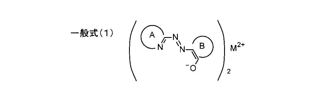
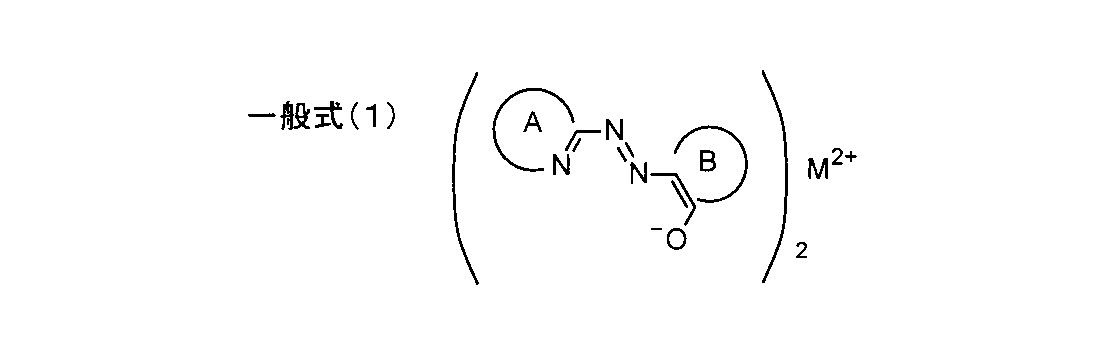
- the recording layer is preferably formed of an azo metal complex dye represented by the following general formula (1). *
- M is a divalent metal selected from Group 7A, Group 8, Group 1B, and Group 2B of the periodic table, and nickel, cobalt, copper, zinc, manganese, and iron are particularly preferable.
- A is a nitrogen-containing heteroaromatic ring
- B has a structure having a saturated or unsaturated 5-membered ring (pentagonal) to 7-membered (hexagonal) hydrocarbon ring or condensed condensed ring. .
- a substrate a reflective layer that reflects light having a wavelength of at least 350 nm to 500 nm on the substrate, a recording layer formed by an organic dye that absorbs light having a wavelength of 350 nm to 500 nm, and 350 nm
- a write once optical recording medium in which a light transmission layer having a single layer structure that transmits light having a wavelength of up to 500 nm is laminated, and has good recording / reproduction characteristics even in a high temperature environment even when the environmental temperature changes.
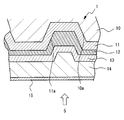
- FIG. 1 is a schematic longitudinal sectional view of an optical recording medium according to a preferred embodiment of the present invention.
- FIG. 1 is a schematic longitudinal sectional view of an optical recording medium according to a preferred embodiment of the present invention. *
- the optical recording medium 1 includes a substrate 10, and a reflective layer 11, a recording layer 12, a protective layer 13, and a light transmissive layer 14 having optical transparency are provided on the substrate 10.
- a hard coat layer 15 that physically protects the light transmission layer 14 and prevents the light transmission layer 14 from being damaged is laminated on the substrate 10 in this order.
- the optical recording medium 1 is configured such that information is recorded by a laser beam 5 having a wavelength of 405 nm, and the recorded information is reproduced, and data is recorded on the recording layer 12 of the optical recording medium 1.
- the recording laser beam 5 for recording and the reproducing laser beam 5 for reproducing the data recorded on the recording layer 12 are optically recorded from the hard coat layer 15 side as indicated by arrows in FIG.
- the medium 1 is configured to be irradiated. *
- the write-once type optical recording medium 1 has a disk shape, and a center hole is formed in the central portion.
- the substrate 10 has a disk shape and functions as a support for ensuring the mechanical strength required for the optical recording medium 1, has a thickness of about 1.1 mm, and a diameter of 120 mm. Yes. *
- the material for forming the substrate 10 is not particularly limited as long as the mechanical strength required for the optical recording medium 1 can be ensured.
- the substrate is made of a metal such as aluminum, glass, ceramics, resin, or the like. 10 can be formed. Of these, from the viewpoints of moldability, moisture resistance, dimensional stability, cost, and the like, resins, particularly thermoplastic resins, are preferably used.
- the resin for forming the substrate 10 include polycarbonate resins; acrylic resins such as polymethyl methacrylate; vinyl chloride resins such as polyvinyl chloride and vinyl chloride copolymers; epoxy resins; amorphous polyolefin resins and polyester resins. It is done. Among these, polycarbonate resin is particularly preferable. *
- a spiral guide groove 10 a is formed on the surface of the substrate 10.
- the spiral guide groove 10a can be formed, for example, by injection molding the substrate 10 using a mold in which a stamper is set.
- the guide groove 10a is formed with a pitch of 0.35 ⁇ m or 0.32 ⁇ m, the width of the guide groove 10a is preferably set to 160 nm to 200 nm, and the depth of the guide groove 10a is preferably 32 nm to 35 nm.
- the width of the guide groove 10a is represented by the half width at the position where the depth of the guide groove 10a is 1/2. *
- a reflective layer 11 is formed by sputtering or the like on the surface of the substrate 10 on the side where the spiral guide groove 10a is formed.
- the reflective layer 11 has a function of reflecting the laser beam 5 irradiated to the optical recording medium 1 and transmitted through the recording layer 12 toward the recording layer 12, and is usually a reflectivity such as an Ag alloy or an Al alloy. Made of high metal.
- the reflective layer 11 is formed of an Ag alloy.
- the reflective layer 11 is preferably formed to have a thickness of 50 nm to 70 nm. *
- the reflective layer 11 is formed on the surface of the substrate 10 on the side where the spiral guide groove 10a is formed, the reflective layer 11 is also formed with the guide groove 11a.
- the width of the guide groove 11a formed in the reflective layer 11 is preferably 150 nm to 190 nm, and the depth of the guide groove 11a is preferably 32 nm to 35 nm.
- a recording layer 12 is formed on the surface of the reflective layer 11, and the recording layer 12 contains an organic dye.
- the recording layer 12 is obtained by dissolving an organic dye in 2,2,3,3-tetrafluoro-1-propanol (TFP), and applying and drying the obtained solution on the surface of the reflective layer 11 by a spin coating method. Is formed by. *
- an organic dye preferably used for forming the recording layer 12 is an azo metal complex dye represented by the general formula (1). *
- a protective layer 13 is formed on the surface of the recording layer 12. *
- the protective layer 13 is formed of a photo-curing resin used for diffusing the organic dye contained in the recording layer 12 into the light transmissive layer 14 or forming the light transmissive layer 14 when the light transmissive layer 14 is formed. This is a layer for preventing the mixing phenomenon that the solvent penetrates into the recording layer 12.
- the material that can form the protective layer 13 is not particularly limited as long as it is a transparent dielectric material.
- silicon oxide silicon dioxide is particularly preferable
- zinc oxide cerium oxide, zirconium oxide
- examples thereof include oxides such as yttrium oxide and indium oxide-tin oxide (ITO); sulfides such as zinc sulfide and yttrium sulfide; nitrides such as silicon nitride; silicon carbide; and a mixture of an oxide and a sulfur compound.
- the protective layer 13 is formed of zinc sulfide-silicon dioxide (ZnS—SiO 2 ), and is formed by sputtering or the like.
- a light transmission layer 14 is formed on the surface of the protective layer 13. *
- the light-transmitting layer 14 is formed by applying a photo-curing resin that is cured by ultraviolet rays or radiation onto the surface of the protective layer 13 by spin coating to form a coating film, and irradiating the coating film with ultraviolet rays or radiation. It is formed by letting.
- the thickness of the light transmission layer 14 is set to 100 ⁇ m together with the thickness of the hard coat layer 15 formed on the light transmission layer 14.
- the light transmission layer 14 is a photocurable resin having an elastic modulus at 75 ° C. of 50 MPa or more and less than 170 MPa after curing, preferably an elastic modulus at 75 ° C. of 51 MPa or more and 154 MPa or less after curing. It is formed of a certain photocurable resin.
- the recording layer 12 is formed by an organic dye that absorbs light having a wavelength of 350 nm to 500 nm, and the optical recording medium 1 provided with the single-layer light transmission layer 14 has a temperature of 75 ° C.
- the light transmission layer 14 is formed so that the elastic modulus is 50 MPa or more and less than 170 MPa, even if the environmental temperature changes, it has good recording / reproduction characteristics and can be stored in a high temperature environment. It has been found that the occurrence of warpage can be suppressed.
- a hard coat layer 15 that physically protects the light transmission layer 14 and prevents the light transmission layer 14 from being damaged is formed on the surface of the light transmission layer 14.
- the material for forming the hard coat layer 15 is not particularly limited, but a material excellent in transparency and wear resistance is preferable.
- the hard coat layer 15 is a resin in which inorganic fine particles are added to an ultraviolet curable resin.
- the composition is preferably formed by applying the composition to the surface of the light transmission layer 14 by a spin coating method. *
- the thickness of the hard coat layer 15 is preferably 1 ⁇ m to 5 ⁇ m. *
- a laser beam having a wavelength of 405 nm from the hard coat layer 15 side and its power set to the recording power Pw. 5 is irradiated.
- the laser beam 5 passes through the hard coat layer 15, the light transmission layer 14 and the protective layer 13 and enters the recording layer 12. Alternatively, the laser beam 5 passes through the recording layer 12 and is reflected by the reflecting layer 11. Incident. *
- the organic dye contained in the region of the recording layer 12 irradiated with the laser beam 5 is thermally decomposed, and the reflectance of the region increases, whereby information is written on the optical recording medium 1.
- the laser beam 5 having a wavelength of 405 nm and its power set to the reproduction power Pr is on the hard coat layer 15 side.
- the information recorded on the recording layer 12 is read out by photoelectrically detecting the light that is irradiated onto the optical recording medium 1 and transmitted through the recording layer 12 and reflected by the reflecting layer 11.
- the light-transmitting layer 14 having a single layer structure is a photocurable resin having an elastic modulus at 75 ° C. after curing of 50 MPa or more and less than 170 MPa, preferably an elastic modulus at 75 ° C. after curing of 51 MPa or more. Since it is made of a photo-curable resin that is 154 MPa or less, it has good recording / reproduction characteristics even when the environmental temperature changes, and suppresses the occurrence of warping even when stored in a high temperature environment. Is possible.
- a dynamic viscoelasticity measuring device “RMAIII” manufactured by TA Instruments was used for measuring the elastic modulus at 75 ° C. The test piece was prepared by applying a photocurable resin to a thickness of 100 ⁇ m on the disk, and after curing, peeling the resin from the disk and cutting it to a size of 5 mm ⁇ 50 mm.
- Example 1 A disk-shaped substrate made of polycarbonate resin having an outer diameter of 120 mm and a thickness of 1.1 mm and having a spiral guide groove formed on the surface with a pitch of 0.32 ⁇ m was produced by injection molding. .
- a reflective layer made of an Ag alloy was formed by sputtering on the surface of the substrate where the guide groove was formed, and a track corresponding to the guide groove having a depth of 33 nm and a width of 175 nm was formed on the surface of the reflective layer.
- the thickness of the reflective layer was 60 nm.
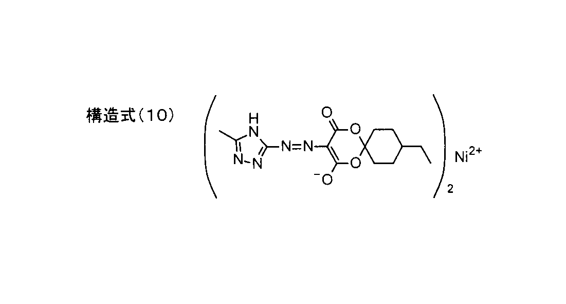
- nickel is used as the divalent metal, and an azo metal complex dye having a triazole structure is added to the nitrogen-containing heteroaromatic ring as 2,2,3,3-tetrafluoro.
- a solution obtained by dissolving in 1-propanol (TFP) was applied to the surface of the reflective layer by spin coating, and dried at 80 ° C. for 30 minutes to form a recording layer having a thickness of 40 nm.
- a protective layer having a thickness of 17 nm was formed on the surface of the recording layer by sputtering ZnS—SiO 2 .
- an ultraviolet curable resin having an elastic modulus of 12 MPa after curing is applied to the surface of the protective layer by a spin coating method to form a coating film, and the coating film is irradiated with ultraviolet rays to be cured.
- a light transmission layer having a thickness of 97 ⁇ m was formed.
- a resin composition in which inorganic fine particles are added to an ultraviolet curable resin is applied to the surface of the light transmission layer by a spin coating method to form a coating film, and the coating film is irradiated with ultraviolet rays to be cured.
- a hard coat layer having a thickness of 3 ⁇ m was formed.
- an optical recording medium sample # 2 was produced in the same manner as in Example 1 except that a light transmission layer was formed using an ultraviolet curable resin having an elastic modulus at 75 ° C. of 30 MPa after curing.
- an optical recording medium was prepared in the same manner as that for producing optical recording medium sample # 1, except that a light transmission layer was formed using an ultraviolet curable resin having an elastic modulus at 75 ° C. of 34 MPa after curing. Sample # 3 was made. *
- optical recording medium was prepared in the same manner as that for producing optical recording medium sample # 1, except that a light transmission layer was formed using an ultraviolet curable resin having an elastic modulus at 75 ° C. of 51 MPa after curing. Sample # 4 was made. *
- an optical recording medium was prepared in the same manner as that for producing optical recording medium sample # 1, except that a light transmission layer was formed using an ultraviolet curable resin having an elastic modulus at 75 ° C. of 69 MPa after curing. Sample # 5 was made. *
- optical recording medium was prepared in the same manner as that for producing optical recording medium sample # 1, except that a light transmission layer was formed using an ultraviolet curable resin having an elastic modulus at 75 ° C. of 83 MPa after curing. Sample # 6 was made. *
- optical recording medium was prepared in the same manner as that for producing the optical recording medium sample # 1, except that the light transmission layer was formed using an ultraviolet curable resin having an elastic modulus at 75 ° C. of 154 MPa after curing. Sample # 7 was made. *
- optical recording medium was prepared in the same manner as that for producing optical recording medium sample # 1, except that a light transmission layer was formed using an ultraviolet curable resin having an elastic modulus at 75 ° C. of 170 MPa after curing. Sample # 8 was made. *
- the environmental temperature was set to 55 ° C., and changes in the information recording / reproducing characteristics of the optical recording medium samples # 1 to # 8 thus obtained at high temperatures were measured.
- optical recording medium samples # 1 to # 8 are sequentially set on an information recording / reproducing apparatus “ODU-1000” (trade name) manufactured by Pulstec Industrial Co., Ltd.
- the surface of the layer was irradiated with a recording laser beam to record data on the recording layer.
- the recording power Pw of the recording laser beam was increased stepwise with respect to the design value P1.
- each sample is set in the information recording / reproducing apparatus, the laser beam whose power is set to the reproducing power Pr is irradiated to the hard coat layer, and the data recorded in the recording layer of each sample is reproduced.
- the recording power P2 of the recording laser beam that cannot be reproduced is obtained.
- a data unrecoverable limit X that is an index that makes it impossible to reproduce data defined by the following equation is obtained.
- the optical recording medium sample was determined as GOOD, and the optical recording medium sample with the information unreproducible limit X of less than 20% was determined as NO GOOD.
- an optical recording medium sample having a data unreproducible limit X of 20% or more is determined as GOOD, and an optical recording medium sample having a data unreproducible limit X of less than 20% is determined as NO GOOD.
- the determination was made when the user actually recorded information on the optical recording medium, due to variations in the performance of the optical recording medium, variations in the performance of the data recording / reproducing apparatus, disturbances, and the like. This is because there is a possibility that information cannot be recorded and reproduced as desired if the data unreproducible limit X is less than 20%.
- the optical recording medium sample # 1 in which the light transmission layer is formed of an ultraviolet curable resin having an elastic modulus at 75 ° C. of 12 MPa after curing has a data non-reproducible limit X of 6.2%, and at 75 ° C. after curing.
- the optical recording medium sample # 2 in which the light transmission layer is formed of an ultraviolet curable resin having an elastic modulus of 30 MPa has a data unrecoverable limit X of 14.3%, and an ultraviolet curable resin having an elastic modulus of 34 MPa at 75 ° C. after curing.
- the optical recording medium sample # 3 in which the light transmission layer is formed of resin has a data non-reproducible limit X of 12.3%, and light having a light transmission layer formed of an ultraviolet curable resin having an elastic modulus at 75 ° C. of 51 MPa after curing.
- the recording medium sample # 4 has a data non-reproducible limit X of 20.0%, and an ultraviolet curable resin having an elastic modulus of 69 MPa at 75 ° C. after curing is optically transparent
- the optical recording medium sample # 5 in which the layer is formed has an unreproducible data reproduction limit X of 22.5%, and the optical recording medium sample # in which the light transmission layer is formed by an ultraviolet curable resin having an elastic modulus of 83 MPa at 75 ° C. after curing.
- the data non-reproducible limit X of No. 6 is 31.2%, and the data non-reproducible limit X of the optical recording medium sample # 7 in which the light transmission layer is formed of an ultraviolet curable resin having an elastic modulus at 75 ° C. of 154 MPa after curing.
- the data unrecoverable limit X of the optical recording medium sample # 8 in which the light transmission layer was formed of an ultraviolet curable resin having an elastic modulus at 75 ° C. of 170 MPa after curing was 38.91%.
- the relationship between the elastic modulus at 75 ° C. of the ultraviolet curable resin forming the light transmission layer and the information reproducibility limit X was obtained in spite of the environmental temperature set at 55 ° C. Even if the temperature is set to 55 ° C., the environmental temperature of the optical recording medium sample set in the information recording / reproducing apparatus is higher than 55 ° C., and ten optical recording medium samples are set in the data recording / reproducing apparatus.
- the ambient temperature of the optical recording medium sample when data was recorded and reproduced was 68.2 ° C. to 74.7 ° C., and ultraviolet light at 75 ° C., which is higher than the highest temperature of 74.7 ° C. This is because it is reasonable to obtain the elastic modulus of the curable resin.
- the optical recording medium samples # 1, 2, and 3 in which the light transmission layer is formed using the ultraviolet curable resin having an elastic modulus of less than 51 MPa at 75 ° C. had an information reproduction non-recovery limit X of less than 20%.
- optical recording medium sample # 6 with a light transmissive layer formed, ultraviolet light with an elastic modulus of 154 MPa at 75 ° C.
- Optical recording medium sample # 7 having a light transmission layer formed using a curable resin and an ultraviolet curable resin having an elastic modulus of 170 MPa at 75 ° C.
- the information reproducibility limit X is 20% or more. From the viewpoint of improving the information recording / reproducing characteristics in a high temperature environment, an ultraviolet ray having an elastic modulus at 75 ° C. of 51 MPa to 170 MPa It has been found that it is preferable to form the light transmission layer using a curable resin.
- Example 2 Each of the optical recording medium samples # 1 to # 8 was held for 10 minutes in a 55 ° C. environment for 10 minutes. Measurement was performed using “SHH-20N”.
- the warp angle of the optical recording medium sample # 2 in which the light transmission layer is formed of an ultraviolet curable resin having an elastic modulus at 75 ° C. of 12 MPa after curing is 0.15 deg, and the elastic modulus at 75 ° C. after curing is 30 MPa.
- the warp angle of the optical recording medium sample # 3 is 0.10 deg
- the warp angle of the optical recording medium sample # 4 in which the light transmission layer is formed of an ultraviolet curable resin having an elastic modulus of 51 MPa at 75 ° C. after curing is 0.05 deg.
- the optical recording medium sample # 5 in which the light transmission layer was formed of an ultraviolet curable resin having an elastic modulus at 75 ° C. of 69 MPa after curing is 0.12 deg, 0.12 deg, at 75 ° C. after curing.
- the optical recording medium sample # 7 in which the light transmission layer is formed of an ultraviolet curable resin having an elastic modulus of 154 MPa has a warp angle of 0.22 deg and light transmission by an ultraviolet curable resin having an elastic modulus at 75 ° C. of 170 MPa after curing.
- the warp angle of the optical recording medium sample # 8 on which the layer was formed was 0.35 deg. *
- the ultraviolet curable resin having an elastic modulus at 75 ° C. after curing of 170 MPa or more When the light transmission layer is formed, the warp angle becomes too large, and the data recording / reproducing characteristics of the optical recording medium are deteriorated.
- the ultraviolet curable resin having an elastic modulus at 75 ° C. of less than 170 MPa after curing can It has been found that when the transmission layer is formed, the data recording / reproducing characteristics of the optical recording medium are not deteriorated by the warp of the optical recording medium.
- an ultraviolet curable resin having an elastic modulus at 75 ° C. after curing of 51 MPa or more and less than 170 MPa particularly an ultraviolet curable resin having an elastic modulus at 75 ° C. after curing of 51 MPa or more and 154 MPa or less.
- the optical recording medium on which the light transmission layer is formed has good recording / reproduction characteristics even when the environmental temperature changes, and it is possible to suppress the occurrence of warping even when stored in a high temperature environment. It has been found.
- the hard coat layer 15 is formed on the surface of the light transmission layer 14, but it is not always necessary to form the hard coat layer 15 on the surface of the light transmission layer 14. Absent.
Landscapes
- Chemical & Material Sciences (AREA)
- Organic Chemistry (AREA)
- Optical Record Carriers And Manufacture Thereof (AREA)
- Thermal Transfer Or Thermal Recording In General (AREA)
Abstract
Description
外線または放射線を照射して、硬化させることによって形成されている。
た。
Claims (4)
- 基板と、基板上に、少なくとも、350nm~500nmの波長の光を反射する反射層と、350nm~500nmの波長の光を吸収する記録層と、350nm~500nmの波長の光を透過する一層構成の光透過層とが積層された光記録媒体であって、前記光透過層の75℃における弾性率が50MPa以上、170MPa未満であることを特徴とする光記録媒体。
- 前記一層構成の光透過層が、光硬化性樹脂を塗布して、塗膜を形成し、光を照射して、塗膜を硬化させることによって形成され、前記光硬化性樹脂の硬化後の75℃における弾性率が51MPa以上、154MPa以下であることを特徴とする請求項1に記載の光記録媒体。
- 前記光硬化性樹脂が、紫外線を照射することによって硬化する紫外線硬化性樹脂であることを特徴とする請求項2に記載の光記録媒体。
- 前記記録層が、下記一般式(1)で表わされるアゾ金属錯体色素によって形成されていることを特徴とする請求項1~3のいずれか1項に記載の追記型の光記録媒体(一般式(1)において、Mは周期律表の7A族、8族、1B族、2B族から選ばれる2価の金属であり、とくにニッケル、コバルト、銅、亜鉛、マンガン、鉄が好ましい。Aは含窒素複素芳香環であり、Bは飽和または不飽和の5員環(5角形)から7員環(6角形)の炭化水素環もしくは複素環の縮合環を有する構造を有している。)。
Priority Applications (3)
| Application Number | Priority Date | Filing Date | Title |
|---|---|---|---|
| CN2012800098812A CN103380460A (zh) | 2011-02-24 | 2012-02-09 | 光记录媒体 |
| US14/001,200 US8945697B2 (en) | 2011-02-24 | 2012-02-09 | Optical recording medium |
| JP2013500949A JPWO2012114884A1 (ja) | 2011-02-24 | 2012-02-09 | 光記録媒体 |
Applications Claiming Priority (2)
| Application Number | Priority Date | Filing Date | Title |
|---|---|---|---|
| JP2011038674 | 2011-02-24 | ||
| JP2011-038674 | 2011-02-24 |
Publications (1)
| Publication Number | Publication Date |
|---|---|
| WO2012114884A1 true WO2012114884A1 (ja) | 2012-08-30 |
Family
ID=46720669
Family Applications (1)
| Application Number | Title | Priority Date | Filing Date |
|---|---|---|---|
| PCT/JP2012/052927 Ceased WO2012114884A1 (ja) | 2011-02-24 | 2012-02-09 | 光記録媒体 |
Country Status (5)
| Country | Link |
|---|---|
| US (1) | US8945697B2 (ja) |
| JP (1) | JPWO2012114884A1 (ja) |
| CN (1) | CN103380460A (ja) |
| TW (1) | TW201237861A (ja) |
| WO (1) | WO2012114884A1 (ja) |
Citations (5)
| Publication number | Priority date | Publication date | Assignee | Title |
|---|---|---|---|---|
| JP2007045147A (ja) * | 2005-07-14 | 2007-02-22 | Mitsubishi Kagaku Media Co Ltd | 光学記録媒体、光記録材料および金属錯体化合物 |
| JP2009016001A (ja) * | 2007-07-06 | 2009-01-22 | Ricoh Co Ltd | 光記録媒体及びその製造方法 |
| JP2009026379A (ja) * | 2007-07-19 | 2009-02-05 | Mitsubishi Kagaku Media Co Ltd | 光記録媒体 |
| JP2010015612A (ja) * | 2008-07-01 | 2010-01-21 | Fujifilm Corp | 光情報記録媒体、情報記録再生方法、および、アゾ金属錯体色素 |
| WO2012011260A1 (ja) * | 2010-07-22 | 2012-01-26 | 日本化薬株式会社 | 光ディスク用紫外線硬化型樹脂組成物、硬化物及び光ディスク |
Family Cites Families (5)
| Publication number | Priority date | Publication date | Assignee | Title |
|---|---|---|---|---|
| JP4550682B2 (ja) * | 2004-07-16 | 2010-09-22 | 三菱化学メディア株式会社 | 光記録媒体及び光記録媒体の光記録方法 |
| EP1903561A4 (en) | 2005-07-14 | 2010-07-21 | Mitsubishi Kagaku Media Co Ltd | OPTICAL RECORDING MEDIUM, OPTICAL RECORDING MATERIAL AND METAL COMPLEX COMPOSITE |
| US8722315B2 (en) * | 2006-05-24 | 2014-05-13 | Dic Corporation | Optical disc and ultraviolet-curable composition for optical disc |
| JP2008071439A (ja) | 2006-09-14 | 2008-03-27 | Ricoh Co Ltd | 光情報記録媒体 |
| JP5094698B2 (ja) * | 2008-12-22 | 2012-12-12 | 太陽誘電株式会社 | 光情報記録媒体用色素及び光情報記録媒体 |
-
2012
- 2012-02-09 JP JP2013500949A patent/JPWO2012114884A1/ja active Pending
- 2012-02-09 US US14/001,200 patent/US8945697B2/en not_active Expired - Fee Related
- 2012-02-09 CN CN2012800098812A patent/CN103380460A/zh active Pending
- 2012-02-09 WO PCT/JP2012/052927 patent/WO2012114884A1/ja not_active Ceased
- 2012-02-20 TW TW101105498A patent/TW201237861A/zh unknown
Patent Citations (5)
| Publication number | Priority date | Publication date | Assignee | Title |
|---|---|---|---|---|
| JP2007045147A (ja) * | 2005-07-14 | 2007-02-22 | Mitsubishi Kagaku Media Co Ltd | 光学記録媒体、光記録材料および金属錯体化合物 |
| JP2009016001A (ja) * | 2007-07-06 | 2009-01-22 | Ricoh Co Ltd | 光記録媒体及びその製造方法 |
| JP2009026379A (ja) * | 2007-07-19 | 2009-02-05 | Mitsubishi Kagaku Media Co Ltd | 光記録媒体 |
| JP2010015612A (ja) * | 2008-07-01 | 2010-01-21 | Fujifilm Corp | 光情報記録媒体、情報記録再生方法、および、アゾ金属錯体色素 |
| WO2012011260A1 (ja) * | 2010-07-22 | 2012-01-26 | 日本化薬株式会社 | 光ディスク用紫外線硬化型樹脂組成物、硬化物及び光ディスク |
Also Published As
| Publication number | Publication date |
|---|---|
| TW201237861A (en) | 2012-09-16 |
| JPWO2012114884A1 (ja) | 2014-07-07 |
| US20140030467A1 (en) | 2014-01-30 |
| US8945697B2 (en) | 2015-02-03 |
| CN103380460A (zh) | 2013-10-30 |
Similar Documents
| Publication | Publication Date | Title |
|---|---|---|
| KR101235104B1 (ko) | 광 정보 기록 매체용 색소 및 광 정보 기록 매체 | |
| JP3995644B2 (ja) | 高密度再生専用光ディスク | |
| TWI386934B (zh) | Optical information recording media | |
| TWI427630B (zh) | Optical information recording media with color and optical information recording media | |
| TWI430269B (zh) | Optical information recording media | |
| TWI381376B (zh) | Optical information recording media | |
| WO2012114884A1 (ja) | 光記録媒体 | |
| TW201331936A (zh) | 光記錄媒體 | |
| JPWO2012114883A1 (ja) | 有機色素を含む記録層を有する追記型光記録媒体 | |
| HK1190491A (en) | Optical recording medium | |
| JP2010282706A (ja) | 光情報記録媒体用色素及びそれを用いた光情報記録媒体 | |
| JPWO2012114886A1 (ja) | 追記型光記録媒体 | |
| JP2013175267A (ja) | 光記録媒体 | |
| JP2013175266A (ja) | 光記録媒体 | |
| JP2008198276A (ja) | 光情報記録媒体 | |
| JP2005014274A (ja) | 光記録媒体 | |
| JPWO2012114885A1 (ja) | 追記型光記録媒体 | |
| HK1190494A (en) | Recordable optical recording medium | |
| KR20100043761A (ko) | 광기록매체 | |
| KR100686104B1 (ko) | 기록 매체 및 기록/재생 방법 | |
| Takazawa et al. | HD DVD-R Disc with Organic Dye having Low to High Polarity Recording | |
| KR20010093358A (ko) | 광기록 매체 | |
| JP2000339755A (ja) | 多層型光ディスク | |
| KR20100043759A (ko) | 광기록매체 | |
| HK1190493A (zh) | 包括含有机色素的记录层的追记型光记录媒体 |
Legal Events
| Date | Code | Title | Description |
|---|---|---|---|
| 121 | Ep: the epo has been informed by wipo that ep was designated in this application |
Ref document number: 12749042 Country of ref document: EP Kind code of ref document: A1 |
|
| ENP | Entry into the national phase |
Ref document number: 2013500949 Country of ref document: JP Kind code of ref document: A |
|
| NENP | Non-entry into the national phase |
Ref country code: DE |
|
| WWE | Wipo information: entry into national phase |
Ref document number: 14001200 Country of ref document: US |
|
| 122 | Ep: pct application non-entry in european phase |
Ref document number: 12749042 Country of ref document: EP Kind code of ref document: A1 |