WO2012114614A1 - データ通信システム、及び、データ通信方法 - Google Patents
データ通信システム、及び、データ通信方法 Download PDFInfo
- Publication number
- WO2012114614A1 WO2012114614A1 PCT/JP2011/079074 JP2011079074W WO2012114614A1 WO 2012114614 A1 WO2012114614 A1 WO 2012114614A1 JP 2011079074 W JP2011079074 W JP 2011079074W WO 2012114614 A1 WO2012114614 A1 WO 2012114614A1
- Authority
- WO
- WIPO (PCT)
- Prior art keywords
- data
- user
- collection condition
- remote monitoring
- monitoring system
- Prior art date
- Legal status (The legal status is an assumption and is not a legal conclusion. Google has not performed a legal analysis and makes no representation as to the accuracy of the status listed.)
- Ceased
Links
Images


Classifications
-
- H—ELECTRICITY
- H04—ELECTRIC COMMUNICATION TECHNIQUE
- H04L—TRANSMISSION OF DIGITAL INFORMATION, e.g. TELEGRAPHIC COMMUNICATION
- H04L67/00—Network arrangements or protocols for supporting network services or applications
- H04L67/01—Protocols
- H04L67/02—Protocols based on web technology, e.g. hypertext transfer protocol [HTTP]
- H04L67/025—Protocols based on web technology, e.g. hypertext transfer protocol [HTTP] for remote control or remote monitoring of applications
Definitions
- the present invention relates to a data communication system and a data communication method for collecting data of devices installed in a store via a network.
- page information referred to by a Web browser or the like is held as a cache in the client PC and the server PC to reduce the amount of data communication between the server PC and the client PC.
- Patent Document 1 when the same data as the cache data held on the client PC side is assigned with the same ID and managed on the server PC side, a new data request is generated from the client PC. When the requested data is not in the cache, the difference between the newly acquired data and all the data in the cache is calculated, and the smallest difference data size is calculated by the client. Return to PC side.
- the client PC reconstructed the actual data from the received difference data and the data on the cache so that it can be used.
- the client PC always makes a data request to the server PC when there is no data identical to the data held in its own cache. Further, the server PC needs to store and manage the same data as the client PC in a cache. Further, when the server PC returns new data to the client PC, there is a problem that it is necessary to calculate a difference from all the data in the cache.
- the present invention has been made to solve the conventional technical problems, and is a data communication system capable of reducing the communication amount and the charge between the remote monitoring system and the store controller with a relatively simple configuration, A data communication method is also provided.
- a data communication system collects data from a connected device and stores the connected device controller and data collected by the connected device controller in response to a data reference request from a user.
- a remote monitoring system that collects, stores, and provides to the user via the remote monitoring system, the remote monitoring system collecting only data of the collection conditions specified by the user from the connected device controller; It is characterized in that it comprises means for assigning a management ID to the collected data for correspondence, and means for registering and managing the ID in the database in association with the collection conditions designated by the user.
- the data communication system of the invention of claim 2 collects and stores data from the connected device, and collects and stores the data collected by the store controller in response to a data reference request from the user via the network.
- a remote monitoring system provided to the user, wherein the remote monitoring system collects only the data of the collection conditions specified by the user from the store controller, and the management ID for the collected data And a means for associating the ID with a collection condition designated by the user, registering them in a database, and managing them.
- the remote monitoring system further includes a new collection condition specified by the user from information registered in the database when a data reference request is issued from the user. If the existing collection condition including the new collection condition is registered in the database, the ID associated with the existing collection condition is set as a new ID.
- a data communication system wherein the remote monitoring system further includes a new collection condition designated by the user from information registered in the database when a data reference request is issued from the user.
- the remote monitoring system when the remote monitoring system further collects data specifying both a new collection condition and an existing collection condition from the store controller, the remote communication system associates with the existing collection condition.
- the remote monitoring system provides the user with a list of collection conditions registered in the database and data that matches the collection conditions selected by the user. And a means for selecting a collection condition from a list provided from a remote monitoring system.
- a data communication method for collecting and storing data from a connected device and collecting and storing data collected by the store controller in response to a data reference request from a user via a network.
- a data communication system is constructed from the remote monitoring system provided to the user, and the remote monitoring system collects only the data of the collection conditions specified by the user from the store controller and assigns a management ID to the collected data.
- the ID is associated with the collection condition specified by the user, registered in the database, managed, and the new collection condition specified by the user at the time of data reference request from the user and the existing registered in the database Compared with the collection conditions of the store, only data that does not exist in the stored data Collected from the roller and providing a data matching the new collection condition to the user.
- the remote monitoring system can acquire only data that does not exist in the data already collected and stored from the store controller in response to the user's data reference request with a simple configuration. As a result, it is possible to reduce the amount of communication between the remote monitoring system and the store controller and the fee generated by the communication.
- the user can refer to the history of collection conditions that have been requested for reference to the remote monitoring system in the past, and for the collection conditions existing in the list, the data of the collection conditions can be obtained simply by selecting it. As a result, it is possible to obtain the information, and it is possible to significantly improve convenience.
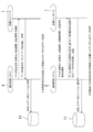
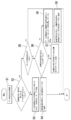
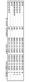
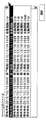
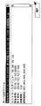
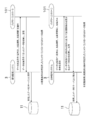
- FIG. 1 is a configuration diagram of a data communication system to which the present invention is applied. It is a figure which shows the communication sequence with the remote monitoring system and shop controller which comprise the data communication system of FIG. It is a flowchart explaining the judgment process at the time of data collection in the remote monitoring system which comprises the data communication system of FIG. It is a flowchart explaining the data creation process in the store controller which comprises the data communication system of FIG. It is a figure which shows the structure of the data collection result management table of the remote monitoring system which comprises the data communication system of FIG. It is a figure which shows the list of the existing collection conditions provided to a user client from the remote monitoring system which comprises the data communication system of FIG. It is a figure which shows the state which the user client selected the uppermost collection conditions of the list of FIG. It is a figure which shows the communication sequence of the remote monitoring system and battery controller to which this invention is applied.
- a data communication system includes a store controller 1 and a store controller 2 installed in a store such as a supermarket or a convenience store, a remote monitoring system 3 serving as a remote monitoring server, and a service person serving as a client. It is constructed from the user client 4 such as a person.
- a store controller is assumed as the connected device controller
- FIG. 8 shows a communication sequence between the remote monitoring system and the battery controller when the battery controller 101 is remotely monitored.
- Each store controller 1, 2 collects and stores data (data related to the operating state including temperature information and alarm information of the device) at regular intervals from all devices such as showcases and air conditioners installed in the store. is doing.
- the remote monitoring system 3 includes a Web application 6, a database 7, a scheduled data collection process 8, a file system 9, and a manual data collection process 11 as its functions.
- the collection process 8 and the database 7 and the manual data collection process 9 and the database 7 are connected by database access, respectively, and between the Web application 6 and the scheduled data collection process 8 and between the Web application 6 and the manual data.
- the collection process 9 is connected by calling a remote method, and the file system 11 and the manual data collection process 9 are connected by file access.
- the store controller 2 is connected to the scheduled data collection process 8 of the remote monitoring system 3 in a socket by a constant connection method. Further, the store controller 1 is connected to the manual data collection processing process 9 of the remote monitoring system 3 by a socket by a packet connection method. Then, the user client 4 is connected to the Web application 6 of the remote monitoring system 3 by the HTTP protocol by a Web browser or the like.
- All data of the equipment collected and stored by the store controller 2 of the always-on connection method is periodically collected by the remote monitoring system 3 by the scheduled data collection processing process 8 and stored in the database 7.
- the user client 4 can search and refer to data stored in the database 7 of the remote monitoring system 3 via the Web application 6 from the Web browser.
- the device data collected and stored by the packet connection type store controller 1 is remotely monitored only when the data reference request from the user client 4 is received, and only the data of the collection conditions designated by the user client 4 is remotely monitored.
- the system 3 collects from the store controller 1 by the manual data collection process 9 and stores it as a file in the file system 11.
- the remote monitoring system 3 provides data that matches the collection conditions requested and specified by the user client 4 from the file stored in the file system 11 to the user client 4 via the Web application 6 and provides it.
- the user client 4 is configured so that the data can be referred to by a Web browser.
- FIG. 2 shows a communication sequence when the remote monitoring system 3 of FIG. 1 acquires data by specifying data collection conditions for the packet connection type store controller 1.
- a (upper) in FIG. 2 is a case where data is collected from the remote monitoring system 3 by specifying only data collection conditions (device terminal ID, collection period, collection interval, etc.).
- the store controller 1 transfers data that meets the collection conditions to the remote monitoring system 3.
- B (lower) in FIG. 2 is a case where data is collected by specifying the collected condition in addition to the collecting condition from the remote monitoring system 3, and has been collected from the remote monitoring system 3 according to the collecting condition.
- the store controller 1 collects only the data that conforms to the collection conditions and does not conform to the collected conditions from the stored data. Forward to 3.
- the remote monitoring system 3 assigns an ID to the data received from the store controller 1 and stores it in the file system 11 as a file.
- FIG. 5 shows a data collection result management table in which the remote monitoring system 3 manages the data files collected and stored from the store controller 1 in response to a data reference request from the user client 4.
- This data collection result management table is stored in the database 7 of the remote monitoring system 3.
- the data management ID is an ID for managing the storage destination of the file collected and stored from the store controller 1
- the collection start time is a measurement time that is the time when the store controller 1 collects the device data.
- the first time that the user client 4 wants to refer to and the collection end time are the same as the last time that the user client 4 wants to refer to
- the collection interval is the fixed interval (the minimum interval that the user client 4 can specify).
- the terminal ID list is the device data collected by the store controller 1.
- a list of IDs of devices that the user client 4 wants to refer to is shown.
- the device ID is an ID uniquely determined and assigned to all devices connected to all the store controllers 1 and 2 connected to the remote monitoring system 3 as described above.
- the user client 4 makes a data reference request to the remote monitoring system 3 by specifying the collection start time, collection end time, collection interval, and terminal ID as a collection condition.
- the remote monitoring system 3 manages the data collection result management table of FIG. 5 based on the following rules. That is, (I). When a data reference request is made from the user client 4, the data collection conditions and the data management ID at that time are registered in association with each other. (B). The data management ID is newly issued when data is downloaded from the store controller 1 and stored. (C). If an existing collection condition that is exactly the same as the new data collection condition is registered, new registration is not performed. (D). When there is an existing collection condition that completely includes the new data collection condition, the same ID as the data management ID associated with the existing collection condition is assigned to collect the new collection condition. Add to the result management table. (E). A collection condition composed of a combination of existing download data and new download data is managed by attaching a data management ID of both.
- FIG. 3 is a flowchart showing a determination method when the remote monitoring system 3 collects data from the store controller 1 in response to a data reference request from the user client 4, and FIG. 4 is a data creation process in the store controller 1. It is a flowchart which shows.
- the remote monitoring system 3 When receiving a data reference request specifying a new collection condition from the user client 4 in step S1 of FIG. 3, the remote monitoring system 3 is registered in the new collection condition and the data collection result management table of FIG. 5 in step S2.
- the existing collection conditions are compared with each other, and it is determined whether or not there is an existing collection condition (data) that includes a part of the new collection conditions.
- step S3 If there is no existing collection condition that includes a part, that is, if the new collection condition is completely different from the existing collection condition, only the new collection condition is determined in step S3. It designates and requests the store controller 1 to acquire data.
- the store controller 1 determines whether or not the data in the data stored by itself in step S10 in FIG. 4 matches the collection condition. Judging. If they match, the process proceeds to step S11. This time, it is determined whether or not the collected condition is specified. Since it is not specified here, the process proceeds to step S13, and the data is stored from the data stored by itself. collect. Then, in step S14, it is determined whether or not all data has been collected. If the data has not been collected, the process returns to step S10 to repeat this. Then, after collecting all data that matches the collection condition, the data is transmitted to the remote monitoring system 3.
- the remote monitoring system 3 collects data from the store controller 1 in this way, adds it to the file system 11 (server), and stores it (A in FIG. 2). Then, a new data management ID corresponding to the collected new data is issued in step S4 of FIG. 3, and the data management ID is associated with the new collection condition and added to the data collection result management table of FIG. .
- step S5 the existing collection condition is registered in the data collection result management table. It is determined whether it is the same as any of the collection conditions.
- the same condition in this case is that the existing collection start time is the same as the new collection start time, the existing collection end time is the same as the new collection end time, and the new collection interval is the existing collection interval.
- the existing terminal ID list is the same as the new terminal ID list.
- the remote monitoring system 3 is associated with the existing collection condition without requesting the store controller 1 to acquire data.
- Data corresponding to the data management ID is read from the file system 11 by the manual data collection process 9 and provided to the user client 4 by the Web application 6. Therefore, in this case, no new registration is performed in FIG.
- step S6 it is determined whether or not the new collection condition is completely included in the existing collection condition.
- the complete inclusion condition in this case is that the existing collection start time is earlier than or the same as the new collection start time, and the existing collection end time is later than or the same as the new collection end time, and a new collection interval. Is a common multiple of the existing collection interval, and the existing terminal ID list includes all the terminal IDs in the new terminal ID list.
- step S7 when the new collection condition is included in any of the existing collection conditions, the process proceeds to step S7, and the new collection condition and the data collection result shown in FIG. Register in the management data table. And, without making a data acquisition request to the store controller 1, it matches the new collection condition from the data stored in the file system 11 corresponding to the data management ID associated with the existing collection condition. Only the data to be extracted is extracted and provided to the user client 4 by the Web application 6.
- the existing collection condition with the data management ID “1” assigned to only the first line in FIG. 5 corresponds to the case where there is a reference request for the second line collection condition. To do. Since the collection condition of the second line is included in the collection condition of the first line, in this case, the existing data management ID “1” is associated with the new collection condition in the data collection result management table of the database 7. Have been added.
- step S8 If the new collection condition is not completely included in the existing collection condition in step S6 of FIG. 3, that is, if it is not the same or completely different and part of them coincides, the process proceeds to step S8.
- This partial match condition is that the existing collection start time is earlier or the same as the new collection start time, or the existing collection end time is later than or the same as the new collection end time, or the new collection interval is The common multiple of the existing collection interval or the existing terminal ID list includes some terminal IDs in the new terminal ID list.
- step S8 of FIG. 3 the remote monitoring system 3 requests the store controller 1 to acquire data by specifying the new collection condition and the collected condition.
- the collected condition is an existing collection condition that partially matches the new collection condition.
- step S10 the data in the data stored in the store controller 1 in step S10 in FIG. 4 matches the collection condition. Determine whether or not. If they match, the process proceeds to step S11, and it is determined whether or not the collected condition is specified. Since it is specified here, the process proceeds to step S12, and the data in the data stored by itself has been collected. It is determined whether the data matches the condition. If the data matches the collected conditions, the process proceeds to step S14. Only when the data does not match the collected conditions, the process proceeds to step S13 and the data is stored from the data stored by itself. collect. Then, in step S14, it is determined whether or not all data has been collected.
- step S10 the process returns to step S10 to repeat this.
- the store controller 1 extracts only data that matches the new collection condition but does not match the collected condition. Then, after collecting all data that matches the new collection condition but does not match the collected condition, the data is transmitted to the remote monitoring system 3.
- the remote monitoring system 3 collects data from the store controller 1 in this way, adds it to the file system 11 (server), and stores it (B in FIG. 2). Then, in step S9 of FIG. 3, a new data management ID corresponding to the collected new data is issued, and both the data management ID and the data management ID associated with the existing collection condition are set as the new collection condition. It associates and adds to the data collection result management table of FIG.
- the remote monitoring system 3 in response to the data reference request of the user client 4, acquires only data that does not exist in the data already collected and stored from the store controller 1, from the store controller 1. It is possible to reduce the amount of communication between the remote monitoring system 3 and the store controller 1 and the charges generated by the communication.
- FIG. 6 shows a collected condition list provided to the user client 4.
- the list in FIG. 6 corresponds to the data collection result management table in FIG.
- User client 4 can select any item in the list of collected conditions presented.
- the remote monitoring system 3 reads data corresponding to the data management ID corresponding to the item from the file system 11 by the manual data collection process 9, and Provided to the user client 4 by the application 6.
- FIG. 7 shows an execution result of re-display when, for example, the item on the second line from the top of FIG. 6 is selected.
- the collection condition data referred to in the past is stored in the remote monitoring system 3 as it is, regardless of the conditions when the data is actually downloaded from the store controller 1.
- the user client 4 can refer to the history of the collection conditions that have been requested to be referred to the remote monitoring system 3 in the past, so that the collection conditions existing in the list can be selected only by selecting the collection conditions. Data can be acquired, and it is possible to significantly improve convenience.
Landscapes
- Engineering & Computer Science (AREA)
- Computer Networks & Wireless Communication (AREA)
- Signal Processing (AREA)
- Telephonic Communication Services (AREA)
- Management, Administration, Business Operations System, And Electronic Commerce (AREA)
Abstract
【課題】比較的簡単な構成で遠隔監視システムと店舗コントローラ間の通信量及び料金を削減することができるデータ通信システムを提供する。 【解決手段】接続機器からのデータを収集し、保存する店舗コントローラ1と、ユーザクライアント4からのデータ参照要求に応じて店舗コントローラが収集したデータをネットワーク経由で収集し、保存すると共に、ユーザクライアントに提供する遠隔監視システム3とから構築される。遠隔監視システムは、ユーザクライアントが指定した収集条件のデータのみを店舗コントローラから収集する手段と、収集したデータに管理用のIDを付与して対応させる手段と、IDとユーザが指定した収集条件とを関連付けてデータベースに登録し、管理する手段とを備える。
Description
本発明は、店舗に設置された機器のデータをネットワーク経由で収集するデータ通信システム、及び、データ通信方法に関するものである。
近年、スーパーマーケットやコンビニエンスストア等の店舗に設置されたショーケースや空気調和機等の機器の計測データを遠隔監視するシステムが開発されてきている。この場合、店舗に設置された機器の各種計測データは当該店舗の店舗コントローラが一定間隔で収集している。遠隔監視システムは店舗コントローラに要求し、当該店舗コントローラが収集したデータをネットワークで接続された遠隔監視サーバにダウンロードして保存する。そして、ユーザはブラウザ等を介して遠隔監視サーバ上のデータを参照できるようにしている。
このとき、常時接続形式のネットワークで接続された店舗コントローラの場合は、定期的に全てのデータを収集してデータベース等で管理することが可能であるが、パケット課金等のネットワークで接続された店舗コントローラの場合には、データ収集に必要となる通信料金が問題となって来る。
ここで、例えば特許文献1では、Webブラウザ等で参照するページ情報を、クライアントPCとサーバPCにキャッシュとして保持し、サーバPCとクライアントPC間のデータ通信量を削減していた。
即ち、特許文献1では、クライアントPC側で保持しているキャッシュデータと同一のデータを同一のIDを付与してサーバPC側で管理し、クライアントPCから新たなデータの要求が発生した場合には、当該要求されたデータがキャッシュに存在しないデータであった場合に、新規に取得したデータとキャッシュに存在している全データとの差分を計算し、その差分データのサイズが最も小さいものをクライアントPC側に返す。
そして、クライアントPCでは受信した差分データとキャッシュ上のデータから実データを再構成し、利用できるようにしていた。
しかしながら、係る従来の通信方式では、クライアントPCは自らのキャッシュに保持されたデータと全く同一のデータが存在しない場合には必ずサーバPCにデータ要求を行うことになる。また、サーバPCはクライアントPCと同一のデータをキャッシュに保持して管理しておく必要がある。更に、サーバPCは新規のデータをクライアントPCに返す際、キャッシュの全てのデータとの差分を計算する必要がある等の問題があった。
本発明は、係る従来の技術的課題を解決するために成されたものであり、比較的簡単な構成で遠隔監視システムと店舗コントローラ間の通信量及び料金を削減することができるデータ通信システム、及び、データ通信方法を提供するものである。
上記課題を解決するために、本発明のデータ通信システムは、接続機器からのデータを収集し、保存する接続機器コントローラと、ユーザからのデータ参照要求に応じて接続機器コントローラが収集したデータをネットワーク経由で収集し、保存すると共に、ユーザに提供する遠隔監視システムとから構築されるものであって、遠隔監視システムは、ユーザが指定した収集条件のデータのみを接続機器コントローラから収集する手段と、収集したデータに管理用のIDを付与して対応させる手段と、IDとユーザが指定した収集条件とを関連付けてデータベースに登録し、管理する手段とを備えることを特徴とする。
請求項2の発明のデータ通信システムは、接続機器からのデータを収集し、保存する店舗コントローラと、ユーザからのデータ参照要求に応じて店舗コントローラが収集したデータをネットワーク経由で収集し、保存すると共に、ユーザに提供する遠隔監視システムとから構築されるものであって、遠隔監視システムは、ユーザが指定した収集条件のデータのみを店舗コントローラから収集する手段と、収集したデータに管理用のIDを付与して対応させる手段と、IDとユーザが指定した収集条件とを関連付けてデータベースに登録し、管理する手段とを備えることを特徴とする。
請求項2の発明のデータ通信システムは、接続機器からのデータを収集し、保存する店舗コントローラと、ユーザからのデータ参照要求に応じて店舗コントローラが収集したデータをネットワーク経由で収集し、保存すると共に、ユーザに提供する遠隔監視システムとから構築されるものであって、遠隔監視システムは、ユーザが指定した収集条件のデータのみを店舗コントローラから収集する手段と、収集したデータに管理用のIDを付与して対応させる手段と、IDとユーザが指定した収集条件とを関連付けてデータベースに登録し、管理する手段とを備えることを特徴とする。
請求項3の発明のデータ通信システムは、上記において遠隔監視システムは更に、ユーザからのデータ参照要求があった場合に、データベースに登録された情報からユーザが指定した新規の収集条件を包含する既存の収集条件が登録されているか否かを判断する手段と、新規の収集条件を包含する既存の収集条件がデータベースに登録されている場合は、当該既存の収集条件と関連付けられたIDを新規の収集条件と関連付けて新たにデータベースに登録する手段と、既存の収集条件と関連付けられたIDに対応するデータから新規の収集条件に合致するデータのみを抜粋してユーザに提供する手段とを備えることを特徴とする。
請求項4の発明のデータ通信システムは、上記各発明において遠隔監視システムは更に、ユーザからのデータ参照要求があった場合に、データベースに登録された情報からユーザが指定した新規の収集条件の一部が一致する既存の収集条件が登録されているか否かを判断する手段と、新規の収集条件と一部が一致する既存の収集条件がデータベースに登録されている場合は、当該新規の収集条件と既存の収集条件の双方を指定して店舗コントローラからデータを収集する手段とを備え、店舗コントローラは、遠隔監視システムから新規の収集条件と既存の収集条件の双方を指定したデータの要求があった場合、新規の収集条件に合致し、且つ、既存の収集条件には合致しないデータのみを抜粋して遠隔監視システムに送信する手段とを備えることを特徴とする。
請求項5の発明のデータ通信システムは、上記において遠隔監視システムは更に、店舗コントローラから新規の収集条件と既存の収集条件の双方を指定したデータの収集を行った場合、既存の収集条件と関連付けられたIDと新規に店舗コントローラから収集したデータに対応させて付与したIDの双方を新規の収集条件と関連付けてデータベースに登録する手段と、当該登録された双方のIDに対応するデータから新規の収集条件に合致するデータのみを抜粋してユーザに提供する手段とを備えることを特徴とする。
請求項6の発明のデータ通信システムは、上記各発明において遠隔監視システムは、データベースに登録された収集条件の一覧をユーザに提供する手段と、当該ユーザが選択した収集条件に合致するデータをユーザに提供する手段とを備え、ユーザは、遠隔監視システムから提供される一覧から収集条件を選択する手段を備えることを特徴とする。
請求項7の発明のデータ通信方法は、接続機器からのデータを収集し、保存する店舗コントローラと、ユーザからのデータ参照要求に応じて店舗コントローラが収集したデータをネットワーク経由で収集し、保存すると共に、ユーザに提供する遠隔監視システムとからデータ通信システムを構築し、遠隔監視システムにより、ユーザが指定した収集条件のデータのみを店舗コントローラから収集し、収集したデータに管理用のIDを付与して対応させ、当該IDとユーザが指定した収集条件とを関連付けてデータベースに登録し、管理すると共に、ユーザからのデータ参照要求時に当該ユーザが指定した新規の収集条件とデータベースに登録されている既存の収集条件とを比較し、保存しているデータ中に存在しないデータのみを店舗コントローラから収集して新規の収集条件に合致するデータをユーザに提供することを特徴とする。
本発明によれば、遠隔監視システムは、簡単な構成にてユーザのデータ参照要求に対し、既に店舗コントローラから収集して保存しているデータ中に存在しないデータのみを店舗コントローラから取得することができるようになり、遠隔監視システムと店舗コントローラ間の通信量並びに当該通信によって発生する料金を削減することが可能となる。
また、ユーザは過去に遠隔監視システムに参照要求した収集条件の履歴を一覧で参照することができるようになり、一覧に存在する収集条件に関しては、それを選択するのみで当該収集条件のデータを取得することができるようになり、著しい利便性の向上を図ることが可能となるものである。
以下、本発明の実施の形態について、詳細に説明する。図1において、実施例のデータ通信システムは、スーパーマーケットやコンビニエンスストア等の店舗に設置された店舗コントローラ1、及び、店舗コントローラ2と、遠隔監視サーバとなる遠隔監視システム3と、クライアントとなるサービス担当者等のユーザクライアント4とから構築される。
また、本実施の形態では接続機器コントローラとして店舗コントローラを想定した場合を記載するが、これに限られるものではなく、遠隔監視の対象となるコントローラであれば本発明を適用することができる。その他の例として、図8はバッテリーコントローラ101を遠隔監視する場合の遠隔監視システムとバッテリーコントローラとの通信シーケンスを示している。
また、本実施の形態では接続機器コントローラとして店舗コントローラを想定した場合を記載するが、これに限られるものではなく、遠隔監視の対象となるコントローラであれば本発明を適用することができる。その他の例として、図8はバッテリーコントローラ101を遠隔監視する場合の遠隔監視システムとバッテリーコントローラとの通信シーケンスを示している。
各店舗コントローラ1、2は、当該店舗に設置されたショーケースや空調機等の全機器から一定の間隔でデータ(機器の温度情報や警報情報等を含む運転状態に関するデータ)を収集し、保存している。
遠隔監視システム3は、その機能としてWebアプリケーション6、データベース7、定時データ収集処理プロセス8、ファイルシステム9、及び、手動データ収集処理プロセス11を備えており、Webアプリケーション6とデータベース7間、定時データ収集処理プロセス8とデータベース7間、及び、手動データ収集処理プロセス9とデータベース7間はそれぞれデータベースアクセスによりそれぞれ接続され、Webアプリケーション6と定時データ収集処理プロセス8間、及び、Webアプリケーション6と手動データ収集処理プロセス9間はリモートメソッド呼び出しにより接続され、ファイルシステム11と手動データ収集処理プロセス9間はファイルアクセスにより接続されている。
店舗コントローラ2は常時接続方式にて遠隔監視システム3の定時データ収集処理プロセス8にソケット(socket)接続されている。また、店舗コントローラ1はパケット接続方式にて遠隔監視システム3の手動データ収集処理プロセス9にソケット(socket)接続されている。そして、遠隔監視システム3のWebアプリケーション6にユーザクライアント4がWebブラウザ等によりHTTPプロトコルで接続される。
常時接続方式の店舗コントローラ2が収集し、保存している機器の全てのデータは、定時データ収集処理プロセス8により定期的に遠隔監視システム3が収集し、データベース7に保存する。ユーザクライアント4は、WebブラウザからWebアプリケーション6経由で遠隔監視システム3のデータベース7に保存されているデータを検索し、参照することができる。
他方、パケット接続方式の店舗コントローラ1が収集し、保存している機器のデータは、ユーザクライアント4からのデータ参照要求があったときのみ、ユーザクライアント4が指定した収集条件のデータのみを遠隔監視システム3が手動データ収集処理プロセス9により店舗コントローラ1から収集し、ファイルシステム11にファイルとして保存する。遠隔監視システム3はファイルシステム11に保存したファイルからユーザクライアント4が要求指定した収集条件に合致したデータをWebアプリケーション6経由でユーザクライアント4に返信して提供する。ユーザクライアント4は、Webブラウザで当該データを参照することができるように構成されている。
次に図2は、図1の遠隔監視システム3がパケット接続方式の店舗コントローラ1に対し、データ収集条件を指定してデータを取得する際の通信シーケンスを示している。図2のA(上段)は、遠隔監視システム3からデータの収集条件(機器の端末ID、収集期間、収集間隔等)のみを指定してデータを収集する場合であり、遠隔監視システム3から収集条件のみを指定してデータ取得の要求が成されると、店舗コントローラ1は収集条件に適合するデータを遠隔監視システム3に転送する。
一方、図2のB(下段)は、遠隔監視システム3からでの収集条件に併せて収集済み条件も指定してデータを収集する場合であり、遠隔監視システム3から収集条件に併せて収集済み条件も指定してデータ取得の要求が成されると、店舗コントローラ1は収集条件に適合し、且つ、収集済み条件には適合しないデータのみを保存しているデータ中から収集し、遠隔監視システム3に転送する。
遠隔監視システム3は何れの場合も、店舗コントローラ1から受信したデータにIDを付与してファイルシステム11にファイルとして保存する。
ここで、図5は遠隔監視システム3がユーザクライアント4からのデータ参照要求に応じて店舗コントローラ1から収集し、保存したデータのファイルとを管理するデータ収集結果管理テーブルを示している。このデータ収集結果管理テーブルは遠隔監視システム3のデータベース7に保存されている。
図5においてデータ管理IDとは、店舗コントローラ1から収集し、保存したファイルの保存先を管理するID、収集開始時刻とは店舗コントローラ1が機器のデータを収集した際の時刻である計測時刻に対してユーザクライアント4が参照したい最初の時刻、収集終了時刻とは同様にユーザクライアント4が参照したい最後の時刻、収集間隔とは店舗コントローラ1が一定の間隔(ユーザクライアント4が指定可能な最小間隔、例えば実施例では10秒間隔等)で収集する機器のデータに対して、ユーザクライアント4が参照したい間隔(例えば60秒間隔等)、端末ID一覧とは店舗コントローラ1が収集した機器のデータに対して、ユーザクライアント4が参照したい機器のIDの一覧をそれぞれ示す。
尚、機器のIDとは前述した如く遠隔監視システム3に接続された全店舗コントローラ1、2のそれぞれに接続された全ての機器に対して一意に決定されて付与されたIDである。そして、ユーザクライアント4は、上記収集開始時刻、収集終了時刻、収集間隔、及び、端末IDを指定して収集条件とし、遠隔監視システム3にデータ参照要求を行うことになる。
次に、遠隔監視システム3は、図5のデータ収集結果管理テーブルを、以下の規則に基づいて管理する。即ち、
(イ).ユーザクライアント4からデータ参照要求が成された際に、そのときのデータの収集条件とデータ管理IDとを関連付けて登録する。
(ロ).データ管理IDは、店舗コントローラ1からデータをダウンロードし、保存した際に新規に発行される。
(ハ).データの新規の収集条件と全く条件が同一の既存の収集条件が登録されている場合は、新規登録は行わない。
(ニ).データの新規の収集条件を完全に包含する既存の収集条件が存在していたときは、当該既存の収集条件と関連付けられているデータ管理IDと同じIDを付与して新規の収集条件をデータ収集結果管理テーブルに追加登録する。
(ホ).既存のダウンロードデータと新規のダウンロードデータの組み合わせで構成される収集条件に対しては、双方のデータ管理IDを付けて管理する。
次に、図3はユーザクライアント4からのデータ参照要求に対して、遠隔監視システム3が店舗コントローラ1からデータを収集する際の判断方法を示すフローチャート、図4は店舗コントローラ1におけるデータの作成処理を示すフローチャートである。図3のステップS1でユーザクライアント4からの新規の収集条件を指定したデータの参照要求を受信すると、遠隔監視システム3はステップS2で新規の収集条件と図5のデータ収集結果管理テーブルに登録されている既存の収集条件とを比較し、新規の収集条件の一部を包含している既存の収集条件(データ)が存在しているか否かを判断する。
そして、一部をも包含している既存の収集条件が存在しない場合、即ち、当該新規の収集条件が既存の収集条件とは完全に異なっている場合、ステップS3で当該新規の収集条件のみを指定して店舗コントローラ1にデータ取得の要求を行う。
店舗コントローラ1は遠隔監視システム3から収集条件のみを指定したデータ取得の要求があると、図4のステップS10で自らが保存しているデータ中の当該データが当該収集条件に一致するか否かを判断する。一致していればステップS11に進み、今度は収集済み条件は指定されているか否かを判断し、ここでは指定されていないのでステップS13に進み、自らが保存しているデータ中から当該データを収集する。そして、ステップS14で全てのデータを収集したか否か判断し、収集が済んでいなければステップS10に戻ってこれを繰り返す。そして、当該収集条件に一致する全てのデータを収集し終えたら、当該データを遠隔監視システム3に送信する。
遠隔監視システム3は、このようにして店舗コントローラ1からデータを収集し、ファイルシステム11(サーバ)に追加して保存する(図2のA)。そして、図3のステップS4で当該収集した新規のデータに対応した新規のデータ管理IDを発行し、当該データ管理IDを新規の収集条件とを関連付けて図5のデータ収集結果管理テーブルに追加する。
例えば、図5中の1行目のみにデータ管理ID「1」が付与された既存の収集条件が登録されている場合に、6行目の収集条件の参照要求があった場合がこれに相当する。この6行目の収集条件は1行目の収集条件と完全に異なっているので、この場合には新規のデータ管理ID「5」が新規に収集したファイルシステム11内のデータに付与され、当該データ管理ID「5」に新規の収集条件が関連付けられてデータベース7のデータ収集結果管理テーブルに追加されている。
次に、図3のステップS2で新規の収集条件と既存の収集条件とが完全には異なっていない場合は、ステップS5に進んで新規の収集条件がデータ収集結果管理テーブルに登録されている既存の収集条件のうちの何れかと同一か否かを判断する。この場合の同一の条件とは、既存の収集開始時刻が新規の収集開始時刻と同一、且つ、既存の収集終了時刻が新規の収集終了時刻と同一、且つ、新規の収集間隔が既存の収集間隔と同一、且つ、既存の端末ID一覧が新規の端末ID一覧と同一であることである。
そして、新規の収集条件と同一の既存の収集条件が存在していた場合には、遠隔監視システム3は、店舗コントローラ1にデータ取得の要求を行うこと無く、当該既存の収集条件と関連付けられたデータ管理IDに対応するデータを手動データ収集処理プロセス9によりファイルシステム11から読み出し、Webアプリケーション6によりユーザクライアント4に提供する。従って、この場合には図5には新規の登録は行われない。
次に、図3のステップS5で新規の収集条件が既存の収集条件と同一では無い場合、ステップS6に進んで今度は新規の収集条件が既存の収集条件に完全に包含されるか否か判断する。この場合の完全包含の条件とは、既存の収集開始時刻が新規の収集開始時刻より早いか同一、且つ、既存の収集終了時刻が新規の収集終了時刻より遅いか同一、且つ、新規の収集間隔が既存の収集間隔の公倍数、且つ、既存の端末ID一覧に新規の端末ID一覧の全ての端末IDが含まれていることである。
そして、新規の収集条件が既存の収集条件の何れかに包含される場合、ステップS7に進んで当該既存の収集条件と関連付けられたデータ管理IDと共に当該新規の収集条件を図5のデータ収集結果管理データテーブルに登録する。そして、店舗コントローラ1にデータ取得の要求を行うこと無く、当該既存の収集条件と関連付けられたデータ管理IDに対応してファイルシステム11に保存されているデータ中から、当該新規の収集条件に合致するデータのみを抜粋し、Webアプリケーション6によりユーザクライアント4に提供する。
例えば、図5中の1行目のみにデータ管理ID「1」が付与された既存の収集条件が登録されている場合に、2行目の収集条件の参照要求があった場合がこれに相当する。この2行目の収集条件は1行目の収集条件に包含されるので、この場合には既存のデータ管理ID「1」が新規の収集条件に関連付けられてデータベース7のデータ収集結果管理テーブルに追加されている。
図3のステップS6で新規の収集条件が既存の収集条件に完全には包含されない場合、即ち、同一でも完全に異なるでも無く、その一部が一致する場合はステップS8に進む。この一部一致の条件とは、既存の収集開始時刻が新規の収集開始時刻より早いか同一、又は、既存の収集終了時刻が新規の収集終了時刻より遅いか同一、又は、新規の収集間隔が既存の収集間隔の公倍数、又は、既存の端末ID一覧に新規の端末ID一覧の一部の端末IDが含まれていることである。
図3のステップS8で、遠隔監視システム3は当該新規の収集条件と、収集済み条件とを指定して店舗コントローラ1にデータ取得の要求を行う。尚、この収集済み条件とは、新規の収集条件と一部が一致する既存の収集条件のことである。
店舗コントローラ1は遠隔監視システム3から収集条件と収集済み条件を指定したデータ取得の要求があると、図4のステップS10で自らが保存しているデータ中の当該データが当該収集条件に一致するか否かを判断する。一致していればステップS11に進み、収集済み条件が指定されているか否かを判断し、ここでは指定されているのでステップS12に進み、自らが保存しているデータ中の当該データが収集済み条件に一致するデータか否か判断する。そして、収集済み条件に一致するデータであった場合には、ステップS14に進み、収集済み条件に一致しないデータである場合のみ、ステップS13に進んで自らが保存しているデータ中から当該データを収集する。そして、ステップS14で全てのデータを収集したか否か判断し、収集が済んでいなければステップS10に戻ってこれを繰り返す。このようにして店舗コントローラ1は、新規の収集条件に合致するが、収集済み条件には合致しないデータのみを抜粋していく。そして、新規の収集条件に合致するが、収集済み条件には合致しない全てのデータを収集し終えたら、当該データを遠隔監視システム3に送信する。
遠隔監視システム3は、このようにして店舗コントローラ1からデータを収集し、ファイルシステム11(サーバ)に追加して保存する(図2のB)。そして、図3のステップS9で当該収集した新規のデータに対応した新規のデータ管理IDを発行し、当該データ管理IDと既存の収集条件に関連付けられたデータ管理IDの双方を新規の収集条件と関連付けて図5のデータ収集結果管理テーブルに追加する。
例えば、図5中の1行目のみにデータ管理ID「1」が付与された既存の収集条件が登録されている場合に、3行目~5行目の収集条件の参照要求があった場合がこれに相当する。これらの収集条件は1行目の収集条件と一部が一致しているので、この場合には新規の収集条件と関連付けられたデータ管理ID「2」、「3」、「4」が新規に収集したファイルシステム11内のデータに付与され、当該データ管理ID「2」、「3」、「4」とデータ管理ID「1」に新規の収集条件が関連付けられてデータベース7のデータ収集結果管理テーブルに追加されている(「1,2」、「1,3」、「1,4」)。
このように本発明では、遠隔監視システム3はユーザクライアント4のデータ参照要求に対し、既に店舗コントローラ1から収集して保存しているデータ中に存在しないデータのみを店舗コントローラ1から取得するので、遠隔監視システム3と店舗コントローラ1間の通信量並びに当該通信によって発生する料金を削減することが可能となる。
また、遠隔監視システム3はユーザクライアント4からデータ参照履歴の要求があった場合、既存の収集条件から収集済み条件一覧を作成し、ユーザクライアント4に提供する。図6はユーザクライアント4に提供される収集済み条件一覧を示している。尚、図6の一覧は図5のデータ収集結果管理テーブルに対応している。
ユーザクライアント4は提示された収集済み条件一覧中の任意の項目を選択することができる。遠隔監視システム3は、ユーザクライアント4により図6中の任意の項目が選択されると、当該項目に対応するデータ管理IDに対応するデータを手動データ収集処理プロセス9によりファイルシステム11から読み出し、Webアプリケーション6によりユーザクライアント4に提供する。図7は例えば図6の上から2行目の項目を選択した場合の再表示の実行結果を示している。
ユーザクライアント4には実際に店舗コントローラ1からデータをダウンロードした際の条件とは関係なく、過去に参照した収集条件のデータがそのまま遠隔監視システム3上に保存されているように見える。
このように、ユーザクライアント4は過去に遠隔監視システム3に参照要求した収集条件の履歴を一覧で参照することができるので、一覧に存在する収集条件に関しては、それを選択するのみで当該収集条件のデータを取得することができるようになり、著しい利便性の向上を図ることが可能となる。
1、2 店舗コントローラ
3 遠隔監視システム
4 ユーザクライアント
7 データベース
11 ファイルシステム
101 バッテリーコントローラ
3 遠隔監視システム
4 ユーザクライアント
7 データベース
11 ファイルシステム
101 バッテリーコントローラ
Claims (7)
- 接続機器からのデータを収集し、保存する接続機器コントローラと、ユーザからのデータ参照要求に応じて前記接続機器コントローラが収集したデータをネットワーク経由で収集し、保存すると共に、前記ユーザに提供する遠隔監視システムとから構築されるデータ通信システムであって、
前記遠隔監視システムは、
前記ユーザが指定した収集条件のデータのみを前記接続機器コントローラから収集する手段と、
収集したデータに管理用のIDを付与して対応させる手段と、
前記IDと前記ユーザが指定した収集条件とを関連付けてデータベースに登録し、管理する手段とを備えることを特徴とするデータ通信システム。 - 接続機器からのデータを収集し、保存する店舗コントローラと、ユーザからのデータ参照要求に応じて前記店舗コントローラが収集したデータをネットワーク経由で収集し、保存すると共に、前記ユーザに提供する遠隔監視システムとから構築されるデータ通信システムであって、
前記遠隔監視システムは、
前記ユーザが指定した収集条件のデータのみを前記店舗コントローラから収集する手段と、
収集したデータに管理用のIDを付与して対応させる手段と、
前記IDと前記ユーザが指定した収集条件とを関連付けてデータベースに登録し、管理する手段とを備えることを特徴とするデータ通信システム。 - 前記遠隔監視システムは、
前記ユーザからのデータ参照要求があった場合に、前記データベースに登録された情報から前記ユーザが指定した新規の収集条件を包含する既存の収集条件が登録されているか否かを判断する手段と、
前記新規の収集条件を包含する既存の収集条件が前記データベースに登録されている場合は、当該既存の収集条件と関連付けられたIDを前記新規の収集条件と関連付けて新たに前記データベースに登録する手段と、
前記既存の収集条件と関連付けられたIDに対応する前記データから前記新規の収集条件に合致するデータのみを抜粋して前記ユーザに提供する手段とを備えることを特徴とする請求項2に記載のデータ通信システム。 - 前記遠隔監視システムは、
前記ユーザからのデータ参照要求があった場合に、前記データベースに登録された情報から前記ユーザが指定した新規の収集条件の一部が一致する既存の収集条件が登録されているか否かを判断する手段と、
前記新規の収集条件と一部が一致する既存の収集条件が前記データベースに登録されている場合は、当該新規の収集条件と既存の収集条件の双方を指定して前記店舗コントローラからデータを収集する手段とを備え、
前記店舗コントローラは、前記遠隔監視システムから前記新規の収集条件と既存の収集条件の双方を指定したデータの要求があった場合、前記新規の収集条件に合致し、且つ、前記既存の収集条件には合致しないデータのみを抜粋して前記遠隔監視システムに送信する手段とを備えることを特徴とする請求項2又は請求項3に記載のデータ通信システム。 - 前記遠隔監視システムは、
前記店舗コントローラから前記新規の収集条件と既存の収集条件の双方を指定したデータの収集を行った場合、前記既存の収集条件と関連付けられたIDと新規に前記店舗コントローラから収集したデータに対応させて付与したIDの双方を前記新規の収集条件と関連付けて前記データベースに登録する手段と、
当該登録された双方のIDに対応する前記データから前記新規の収集条件に合致するデータのみを抜粋して前記ユーザに提供する手段とを備えることを特徴とする請求項4に記載のデータ通信システム。 - 前記遠隔監視システムは、
前記データベースに登録された前記収集条件の一覧を前記ユーザに提供する手段と、
当該ユーザが選択した収集条件に合致するデータを前記ユーザに提供する手段とを備え、
前記ユーザは、
前記遠隔監視システムから提供される前記一覧から前記収集条件を選択する手段を備えることを特徴とする請求項2乃至請求項5のうちの何れかに記載のデータ通信システム。 - 接続機器からのデータを収集し、保存する店舗コントローラと、ユーザからのデータ参照要求に応じて前記店舗コントローラが収集したデータをネットワーク経由で収集し、保存すると共に、前記ユーザに提供する遠隔監視システムとからデータ通信システムを構築し、
前記遠隔監視システムにより、前記ユーザが指定した収集条件のデータのみを前記店舗コントローラから収集し、収集したデータに管理用のIDを付与して対応させ、当該IDと前記ユーザが指定した収集条件とを関連付けてデータベースに登録し、管理すると共に、
前記ユーザからのデータ参照要求時に当該ユーザが指定した新規の収集条件と前記データベースに登録されている既存の収集条件とを比較し、保存しているデータ中に存在しないデータのみを前記店舗コントローラから収集して前記新規の収集条件に合致するデータを前記ユーザに提供することを特徴とするデータ通信方法。
Applications Claiming Priority (2)
| Application Number | Priority Date | Filing Date | Title |
|---|---|---|---|
| JP2011040278A JP2014089488A (ja) | 2011-02-25 | 2011-02-25 | データ通信システム、及び、データ通信方法 |
| JP2011-040278 | 2011-02-25 |
Publications (1)
| Publication Number | Publication Date |
|---|---|
| WO2012114614A1 true WO2012114614A1 (ja) | 2012-08-30 |
Family
ID=46720416
Family Applications (1)
| Application Number | Title | Priority Date | Filing Date |
|---|---|---|---|
| PCT/JP2011/079074 Ceased WO2012114614A1 (ja) | 2011-02-25 | 2011-12-15 | データ通信システム、及び、データ通信方法 |
Country Status (2)
| Country | Link |
|---|---|
| JP (1) | JP2014089488A (ja) |
| WO (1) | WO2012114614A1 (ja) |
Citations (4)
| Publication number | Priority date | Publication date | Assignee | Title |
|---|---|---|---|---|
| JPH04303261A (ja) * | 1991-03-29 | 1992-10-27 | Nec Corp | 分散型関係データベースにおける水平分割抽出による重複データの検索方法 |
| JP2001142895A (ja) * | 1999-11-15 | 2001-05-25 | Shimadzu Corp | 分散型制御システム |
| JP2007193436A (ja) * | 2006-01-17 | 2007-08-02 | Fujitsu Ltd | ログ検索プログラム、ログ管理装置、情報処理装置およびログ検索方法 |
| JP2010020358A (ja) * | 2008-06-13 | 2010-01-28 | Sanyo Electric Co Ltd | 機器管理装置 |
-
2011
- 2011-02-25 JP JP2011040278A patent/JP2014089488A/ja not_active Withdrawn
- 2011-12-15 WO PCT/JP2011/079074 patent/WO2012114614A1/ja not_active Ceased
Patent Citations (4)
| Publication number | Priority date | Publication date | Assignee | Title |
|---|---|---|---|---|
| JPH04303261A (ja) * | 1991-03-29 | 1992-10-27 | Nec Corp | 分散型関係データベースにおける水平分割抽出による重複データの検索方法 |
| JP2001142895A (ja) * | 1999-11-15 | 2001-05-25 | Shimadzu Corp | 分散型制御システム |
| JP2007193436A (ja) * | 2006-01-17 | 2007-08-02 | Fujitsu Ltd | ログ検索プログラム、ログ管理装置、情報処理装置およびログ検索方法 |
| JP2010020358A (ja) * | 2008-06-13 | 2010-01-28 | Sanyo Electric Co Ltd | 機器管理装置 |
Also Published As
| Publication number | Publication date |
|---|---|
| JP2014089488A (ja) | 2014-05-15 |
Similar Documents
| Publication | Publication Date | Title |
|---|---|---|
| JP4997950B2 (ja) | ネットワーク管理システム、ネットワーク管理プログラムおよびネットワーク管理方法 | |
| JP2011180946A (ja) | センサデータ提供システム、方法及び装置 | |
| JP2012164369A (ja) | センサデータ提供システム、ゲートウェイ及び抽象化センサデータ生成方法 | |
| CN103763122A (zh) | 一种故障信息的处理方法和服务系统 | |
| JP7150584B2 (ja) | エッジサーバとそのプログラム | |
| JP6603645B2 (ja) | リソース検索装置およびリソース検索方法 | |
| JPWO2016157271A1 (ja) | センサネットワークシステム | |
| WO2018110095A1 (ja) | 制御装置、センサ管理装置、制御方法、センサ管理方法およびプログラム | |
| WO2013024672A1 (ja) | 情報管理装置、情報管理プログラム、および情報管理方法 | |
| JP5072464B2 (ja) | 画像提供装置、画像提供方法、画像提供プログラムおよびそのプログラムを記録したコンピュータ読み取り可能な記録媒体 | |
| EP3432145B1 (en) | Data-flow control device and data-flow control method | |
| US10789307B2 (en) | Cloud-based discovery and inventory | |
| JP2009181334A (ja) | 情報管理代行装置、サービス提供システムおよびサービス提供方法 | |
| JP5778621B2 (ja) | データ流通管理システム | |
| JP2010134516A (ja) | 入退室情報管理装置および入退室情報管理方法 | |
| JP2014089488A (ja) | データ通信システム、及び、データ通信方法 | |
| KR20210039732A (ko) | 에너지 관련 데이터를 처리 및 관리하기 위한 장치 및 방법 | |
| JP5665493B2 (ja) | データ提供方法及びデータ提供サーバ | |
| JP2021157340A (ja) | データ連携システムおよびapiプラットフォーム | |
| WO2017119094A1 (ja) | サービス連携システムおよびサービス連携方法 | |
| JP2005352807A (ja) | 調査方法及びプログラム | |
| JP2014038454A (ja) | ユーザデータ保存先判定サーバ、通信装置及びユーザデータ保存先判定方法 | |
| JP2010231423A (ja) | 消費情報地図表示装置、消費情報地図表示システム、および消費情報地図表示方法 | |
| JP6868536B2 (ja) | データ収集装置およびデータ収集システム | |
| EP3432593A1 (en) | Data-flow control device and data-flow control method |
Legal Events
| Date | Code | Title | Description |
|---|---|---|---|
| 121 | Ep: the epo has been informed by wipo that ep was designated in this application |
Ref document number: 11859540 Country of ref document: EP Kind code of ref document: A1 |
|
| NENP | Non-entry into the national phase |
Ref country code: DE |
|
| 122 | Ep: pct application non-entry in european phase |
Ref document number: 11859540 Country of ref document: EP Kind code of ref document: A1 |
|
| NENP | Non-entry into the national phase |
Ref country code: JP |