WO2012111753A1 - レバー式コネクタ - Google Patents
レバー式コネクタ Download PDFInfo
- Publication number
- WO2012111753A1 WO2012111753A1 PCT/JP2012/053671 JP2012053671W WO2012111753A1 WO 2012111753 A1 WO2012111753 A1 WO 2012111753A1 JP 2012053671 W JP2012053671 W JP 2012053671W WO 2012111753 A1 WO2012111753 A1 WO 2012111753A1
- Authority
- WO
- WIPO (PCT)
- Prior art keywords
- lever
- connector
- connector housing
- mounting plate
- housing
- Prior art date
- Legal status (The legal status is an assumption and is not a legal conclusion. Google has not performed a legal analysis and makes no representation as to the accuracy of the status listed.)
- Ceased
Links
Images





Classifications
-
- H—ELECTRICITY
- H01—ELECTRIC ELEMENTS
- H01R—ELECTRICALLY-CONDUCTIVE CONNECTIONS; STRUCTURAL ASSOCIATIONS OF A PLURALITY OF MUTUALLY-INSULATED ELECTRICAL CONNECTING ELEMENTS; COUPLING DEVICES; CURRENT COLLECTORS
- H01R13/00—Details of coupling devices of the kinds covered by groups H01R12/70 or H01R24/00 - H01R33/00
- H01R13/46—Bases; Cases
- H01R13/52—Dustproof, splashproof, drip-proof, waterproof, or flameproof cases
- H01R13/5205—Sealing means between cable and housing, e.g. grommet
-
- H—ELECTRICITY
- H01—ELECTRIC ELEMENTS
- H01R—ELECTRICALLY-CONDUCTIVE CONNECTIONS; STRUCTURAL ASSOCIATIONS OF A PLURALITY OF MUTUALLY-INSULATED ELECTRICAL CONNECTING ELEMENTS; COUPLING DEVICES; CURRENT COLLECTORS
- H01R13/00—Details of coupling devices of the kinds covered by groups H01R12/70 or H01R24/00 - H01R33/00
- H01R13/62—Means for facilitating engagement or disengagement of coupling parts or for holding them in engagement
- H01R13/629—Additional means for facilitating engagement or disengagement of coupling parts, e.g. aligning or guiding means, levers, gas pressure electrical locking indicators, manufacturing tolerances
-
- H—ELECTRICITY
- H01—ELECTRIC ELEMENTS
- H01R—ELECTRICALLY-CONDUCTIVE CONNECTIONS; STRUCTURAL ASSOCIATIONS OF A PLURALITY OF MUTUALLY-INSULATED ELECTRICAL CONNECTING ELEMENTS; COUPLING DEVICES; CURRENT COLLECTORS
- H01R13/00—Details of coupling devices of the kinds covered by groups H01R12/70 or H01R24/00 - H01R33/00
- H01R13/46—Bases; Cases
- H01R13/52—Dustproof, splashproof, drip-proof, waterproof, or flameproof cases
-
- H—ELECTRICITY
- H01—ELECTRIC ELEMENTS
- H01R—ELECTRICALLY-CONDUCTIVE CONNECTIONS; STRUCTURAL ASSOCIATIONS OF A PLURALITY OF MUTUALLY-INSULATED ELECTRICAL CONNECTING ELEMENTS; COUPLING DEVICES; CURRENT COLLECTORS
- H01R13/00—Details of coupling devices of the kinds covered by groups H01R12/70 or H01R24/00 - H01R33/00
- H01R13/62—Means for facilitating engagement or disengagement of coupling parts or for holding them in engagement
- H01R13/629—Additional means for facilitating engagement or disengagement of coupling parts, e.g. aligning or guiding means, levers, gas pressure electrical locking indicators, manufacturing tolerances
- H01R13/62933—Comprising exclusively pivoting lever
-
- H—ELECTRICITY
- H01—ELECTRIC ELEMENTS
- H01R—ELECTRICALLY-CONDUCTIVE CONNECTIONS; STRUCTURAL ASSOCIATIONS OF A PLURALITY OF MUTUALLY-INSULATED ELECTRICAL CONNECTING ELEMENTS; COUPLING DEVICES; CURRENT COLLECTORS
- H01R13/00—Details of coupling devices of the kinds covered by groups H01R12/70 or H01R24/00 - H01R33/00
- H01R13/73—Means for mounting coupling parts to apparatus or structures, e.g. to a wall
- H01R13/74—Means for mounting coupling parts in openings of a panel
-
- H—ELECTRICITY
- H01—ELECTRIC ELEMENTS
- H01R—ELECTRICALLY-CONDUCTIVE CONNECTIONS; STRUCTURAL ASSOCIATIONS OF A PLURALITY OF MUTUALLY-INSULATED ELECTRICAL CONNECTING ELEMENTS; COUPLING DEVICES; CURRENT COLLECTORS
- H01R13/00—Details of coupling devices of the kinds covered by groups H01R12/70 or H01R24/00 - H01R33/00
- H01R13/73—Means for mounting coupling parts to apparatus or structures, e.g. to a wall
- H01R13/74—Means for mounting coupling parts in openings of a panel
- H01R13/741—Means for mounting coupling parts in openings of a panel using snap fastening means
Definitions
- the present invention relates to a lever-type connector in which a first connector housing and a second connector housing are fitted and connected by a lever turning operation, and a waterproof grommet is attached to the first connector housing. .
- the lever-type connector 100 shown here is disclosed in the following Patent Document 1, and is used, for example, to connect a cable (electric wire) 160 inside and outside a connector mounting plate (panel) 150 such as a door panel of a vehicle.
- the fitting connection between the first connector housing 110 and the second connector housing 120 is achieved by the turning operation of the lever 130 attached to the first connector housing 110.
- the lever 130 has a cover shape for accommodating the first connector housing 110 as shown in FIG. As shown in FIG. 7, a grommet 140 for waterproofing the first connector housing 110 is attached to the lever 130 that houses the first connector housing 110.
- the lever-type connector 100 in which the first connector housing 110 and the second connector housing 120 have been fitted and connected has the connector mounting plate 150 with the grommet 140 mounted on the lever 130. Attached to.
- the grommet 140 has a panel fitting portion 141 that press-fits into the connector mounting hole 151 of the connector mounting plate 150 when the lever-type connector 100 is mounted on the connector mounting plate 150.
- the panel fitting portion 141 is closely fitted to the peripheral edge portion of the connector attachment hole 151 and waterproofs the connector attachment hole 151 through which the lever connector 100 is inserted.
- the lever-type connector 100 of Patent Document 1 has a problem that it takes time to press-fit the panel fitting portion 141 into the connector mounting hole 151, and the grommet 140 is not easily mounted.
- the lever connector 100 is fixed to the connector mounting plate 150 via the panel fitting portion 141 of the grommet 140, and acts on the lever connector 100 from the cable 160 connected to the lever connector 100. Since the tensile load and the bending load act on the panel fitting portion 141, there is a problem that the grommet 140 is easily damaged.
- an object of the present invention is to eliminate the above-mentioned problems, and it is not necessary to press-fit the grommet into the connector mounting hole of the connector mounting plate, so that the grommet can be easily mounted and acts on the connector housing via the cable.
- An object of the present invention is to provide a lever-type connector that can prevent a grommet from being damaged by a load to be applied.
- a first connector housing A second connector housing attached to the connector mounting plate in a state of having a distal end fitting portion to which the distal end portion of the first connector housing is fitted and connected, and being inserted through a connector mounting hole of the connector mounting plate;
- a lever-type connector comprising: The lever is formed separately from the first connector housing, and the rear end of the first connector housing abutted against the second connector housing attached to the connector mounting plate is used as the second connector housing.
- a lever body for pressing the connector housing side, and one end of the lever body is rotatably connected to the connector mounting plate, and the lever body connects the rear end of the first connector housing to the second connector.
- a connecting portion for rotation that enables a lever behavior to be pressed toward the housing side and a lever connecting portion provided on the other end side of the lever main body between the first connector housing and the second connector housing by the lever behavior of the lever main body.
- the grommet is integrally formed with the lever cover portion by a lip portion having a groove portion fitted to the outer peripheral edge of the lever body, and is connected to the first connector housing.
- a lever-type connector that is in close contact with the first connector housing to ensure waterproofness inside the first connector housing.
- the grommet that secures waterproofing that prevents water and the like from entering the first connector housing is formed separately from the first connector housing, and the connector mounting plate It is fitted and attached to a lever that is pivotably attached to the connector, and is brought into close contact with the connector mounting plate by a pivoting operation of the lever to exhibit waterproofness.
- the grommet is attached to the connector mounting plate separately from the first connector housing and the second connector housing.
- the load acting on these connector housings via the cables is unlikely to act on the grommets. Therefore, it is possible to prevent the grommet from being damaged by a load acting on these connector housings via the cable.
- FIG. 1 is an exploded perspective view of an embodiment of a lever-type connector according to the present invention.
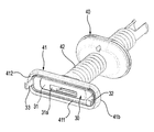
- FIG. 2 is a perspective view of the grommet fitted to the lever shown in FIG.
- FIG. 3 is a plan view showing a state in which one end of the lever shown in FIG. 1 is rotatably coupled to the connector mounting plate.
- FIG. 4 is a plan view showing a state in which the fitting connection between the first connector housing and the second connector housing is completed by the lever behavior of the lever shown in FIG.
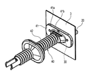
- FIG. 5 is a perspective view of a state in which the first connector housing and the second connector housing shown in FIG. 1 have been fitted and connected, and the first connector housing is waterproofed by the grommet.
- FIG. 1 is an exploded perspective view of an embodiment of a lever-type connector according to the present invention.
- FIG. 2 is a perspective view of the grommet fitted to the lever shown in FIG.
- FIG. 3 is a plan view showing a state in which one end of the lever shown in FIG.
- FIG. 6 is an exploded perspective view of a first connector housing and a second connector housing constituting a conventional lever-type connector.
- FIG. 7 is a perspective view of a grommet mounted on the first connector housing shown in FIG.
- FIG. 8 is a perspective view showing a state before the lever-type connector shown in FIG. 6 is fixed to the connector mounting plate.
- the lever-type connector 1 of this embodiment is used, for example, for connection of a cable (electric wire) (not shown) inside and outside a connector mounting plate 3 serving as a vehicle panel.
- a cable electric wire
- connector mounting plate 3 serving as a vehicle panel.
- connector housing 10 As shown in FIG. 1 and FIG. 1 connector housing 10, second connector housing 20, lever 30, and grommet 40.
- the first connector housing 10 is a connector housing to which a cable on the outside of the connector mounting plate 3 is connected. As for this 1st connector housing 10, the front-end
- the second connector housing 20 is a standby connector that waits on the connector mounting plate 3 for fitting connection with the first connector housing 10.
- the second connector housing 20 has a tip fitting portion 21 to which the first connector housing 10 is fitted and connected. Further, as shown in FIG. 1, the second connector housing 20 is engaged and fixed to the connector mounting plate 3 in a state where the tip fitting portion 21 is inserted through the connector mounting hole 3 a of the connector mounting plate 3.
- the second connector housing 20 is fixed to the connector mounting plate 3 when the tip fitting portion 21 is inserted into the connector mounting hole 3a without being connected to the first connector housing 10.
- the panel fixing piece 22 which fulfill
- the panel fixing pieces 22 are provided on the left and right sides of the tip fitting portion 21.
- the lever 30 fits the first connector housing 10 to the second connector housing 20 by a turning operation.
- the lever 30 of the present embodiment is an independent component separate from the first connector housing 10, and as shown in FIG. 3, the lever main body 31, the rotation connecting portion 32, and the lever lock piece 33 are provided. Prepare.
- the lever body 31 is formed separately from the first connector housing 10. As shown in FIGS. 3 and 4, the lever main body 31 is configured such that the rear end of the first connector housing 10 abutted against the second connector housing 20 attached to the connector attachment plate 3 is connected to the second connector housing 20. It is a plate-shaped member for pressing to the side.
- the lever main body 31 has a substantially oval shape, and as shown in FIG. 1, an opening 31a for inserting a cable is formed at the center.
- the rotation connecting portion 32 is provided in an arm portion 32 a extending substantially perpendicularly from the lever main body 31 on one end side of the lever main body 31, and in a hook shape at the tip of the arm portion 32 a.
- the engaging claw portion 32b As shown in FIG. 3, the locking claw portion 32 b engages with a first lever support hole 3 b (see FIG. 1) provided in the connector mounting plate 3, so that one end side of the lever 30 can be rotated. Connect to the connector mounting plate 3.
- the rotating connecting portion 32 described above connects one end of the lever body 31 to the connector mounting plate 3 so as to be rotatable, and the lever body 31 is connected to the first connector housing 10 as shown in FIGS.
- a lever behavior (leverage operation) for pressing the rear end toward the second connector housing 20 is enabled.
- An arrow R shown in FIG. 3 indicates a rotation direction when the lever 30 performs a lever behavior.
- the lever lock piece 33 includes an arm portion 33 a extending substantially perpendicularly from the lever main body 31 on the other end side of the lever main body 31, and orthogonal to the arm portion 33 a from the tip of the arm portion 33 a. And a locking projection 33b protruding to the outer side. As shown in FIG. 4, the locking projection 33b engages with a second lever support hole 3c (see FIG. 1) provided in the connector mounting plate 3, so that the other end of the lever 30 is connected to the connector mounting plate. Fix to 3.
- the lever lock piece 33 described above is provided on the other end side of the lever main body 31, and the lever behavior of the lever main body 31 causes the first connector housing 10 and the second connector housing 20 to move as shown in FIG. 4.
- the other end side of the lever main body 31 is fixed to the connector mounting plate 3.
- the grommet 40 is fitted and attached to the lever 30 to ensure waterproofness that prevents water and the like from entering the first connector housing 10.
- the grommet 40 is made of an elastic material having waterproof properties such as synthetic rubber. As shown in FIGS. 2 and 5, the grommet 40 is integrally formed with the lever covering portion 41 to be fitted and attached to the lever 30. A tubular portion 42. The tubular portion 42 accommodates a cable connected to the first connector housing 10.
- the lever covering portion 41 is formed by forming a lip portion 41 b on the entire circumference of the outer peripheral edge of the substantially oval covering portion main body 41 a covering the outer surface side of the lever main body 31.
- the lip portion 41 b includes a groove portion 411 that fits to the outer peripheral edge of the lever main body 31 and a protruding strip portion 412 that extends toward the connector mounting plate 3.
- the lever covering portion 41 is fixed to the lever 30 by fitting the groove portion 411 of the lip portion 41 b to the outer peripheral edge of the lever main body 31.
- the protrusion 412 of the lip portion 41b is brought into close contact with the peripheral edge of the connector mounting hole 3a when the lever housing 30 has been fitted to each other by the lever behavior.
- the waterproof property to prevent the entry of water or the like into the first connector housing 10 is ensured.
- the grommet 40 that secures the waterproof property inside the first connector housing 10 is formed separately from the first connector housing 10, and the connector mounting plate 3.
- the lever 30 is pivotally attached to the connector 30 and is attached to the connector mounting plate 3 by the turning operation of the lever 30 to exhibit waterproofness.
- the grommet 40 is attached to the connector mounting plate 3 separately from the first connector housing 10 and the second connector housing 20.
- the load acting on these connector housings acts on the grommet 40 via the cable. It is hard to do. Therefore, it is possible to prevent the grommet 40 from being damaged by a load acting on these connector housings via the cable.
- the mounting location of the second connector housing is not limited to a panel in a vehicle or the like, and may be a wall surface of a case for various electronic / electrical devices.
- This application is based on a Japanese patent application filed on Feb. 17, 2011 (Japanese Patent Application No. 2011-032358), the contents of which are incorporated herein by reference.
- the grommet that secures the waterproofness inside the first connector housing is fitted and attached to a lever that is rotatably attached to the connector attachment plate, and the connector is attached by rotating the lever. It adheres to the plate and exhibits water resistance. Therefore, it is not necessary to press-fit the grommet into the connector mounting hole of the connector mounting plate, and it becomes easier to install the grommet compared to the conventional case where a part of the grommet is press-fitted into the connector mounting hole of the connector mounting plate. Assembling property can be improved.
- the first connector housing and the second connector housing are attached to the connector mounting plate without going through the grommets, the load acting on these connector housings via the cables is unlikely to act on the grommets. Therefore, it is possible to prevent the grommet from being damaged by a load acting on these connector housings via the cable.
Landscapes
- Connector Housings Or Holding Contact Members (AREA)
- Details Of Connecting Devices For Male And Female Coupling (AREA)
Abstract
Description
ここに示したレバー式コネクタ100は、下記特許文献1に開示されたもので、例えば、車両のドアパネル等のコネクタ取付板(パネル)150の内外のケーブル(電線)160の接続に使用される。
(1)第1のコネクタハウジングと、
前記第1のコネクタハウジングの先端部が嵌合接続される先端嵌合部を有すると共に、コネクタ取付板のコネクタ取付孔を挿通した状態で前記コネクタ取付板に取り付けられる第2のコネクタハウジングと、
回動操作によって前記第1のコネクタハウジングを前記第2のコネクタハウジングに嵌合させるレバーと、
前記第1のコネクタハウジング内部の防水性を確保するグロメットと、
を備えるレバー式コネクタであって、
前記レバーは、前記第1のコネクタハウジングとは別体に形成されて前記コネクタ取付板に取り付けられた前記第2のコネクタハウジングに突き合された前記第1のコネクタハウジングの後端を前記第2のコネクタハウジング側に押圧するためのレバー本体と、該レバー本体の一端を前記コネクタ取付板に回動可能に連結して前記レバー本体が前記第1のコネクタハウジングの後端を前記第2のコネクタハウジング側に押圧するてこ挙動を可能にする回動用連結部と、前記レバー本体の他端側に設けられて前記レバー本体のてこ挙動により前記第1のコネクタハウジングと前記第2のコネクタハウジングとの嵌合が完了したときに前記レバー本体の他端側を前記コネクタ取付板に固定するレバーロック片と、を備え、
前記グロメットは、前記レバー本体の外周縁に嵌合する溝部を有したリップ部により前記レバー本体に結合されるレバー被覆部と、該レバー被覆部に一体形成されて前記第1のコネクタハウジングに接続されるケーブルを収容する管状部と、を備えて前記レバーに被嵌装着され、前記レバーのてこ挙動によってコネクタハウジング相互の嵌合が完了した状態では、前記リップ部が前記コネクタ取付孔の周縁に密着して前記第1のコネクタハウジング内部の防水性を確保するレバー式コネクタ。
この一実施形態のレバー式コネクタ1は、例えば車両のパネルとなるコネクタ取付板3の内外の図示しないケーブル(電線)の接続に使用されるもので、図1及び図2に示すように、第1のコネクタハウジング10と、第2のコネクタハウジング20と、レバー30と、グロメット40と、を備える。
図3に示す矢印Rは、レバー30がてこ挙動をするときの回動方向を示している。
また、本出願は、2011年2月17日出願の日本特許出願(特願2011-032358)に基づくものであり、その内容はここに参照として取り込まれる。
従って、グロメットをコネクタ取付板のコネクタ取付孔に圧入する作業が必要無く、グロメットの一部をコネクタ取付板のコネクタ取付孔に圧入していた従来の場合と比較すると、グロメットの装着が容易になり、組立性を向上させることができる。
しかも、第1のコネクタハウジングや第2のコネクタハウジングは、グロメットを介さずにコネクタ取付板に取り付けられるため、ケーブルを介してこれらコネクタハウジングに作用する荷重がグロメットに作用し難い。従って、ケーブルを介してこれらコネクタハウジングに作用する荷重によってグロメットが傷むことを防止することもできる。
3 コネクタ取付板
3a コネクタ取付孔
3b 第1のレバー支持孔
3c 第2のレバー支持孔
10 第1のコネクタハウジング
11 先端部
20 第2のコネクタハウジング
21 先端嵌合部
22 パネル固定片
30 レバー
31 レバー本体
32 回動用連結部
33 レバーロック片
40 グロメット
41 レバー被覆部
41a 被覆部本体
41b リップ部
42 管状部
411 溝部
412 凸条部
Claims (1)
- 第1のコネクタハウジングと、
前記第1のコネクタハウジングの先端部が嵌合接続される先端嵌合部を有すると共に、コネクタ取付板のコネクタ取付孔を挿通した状態で前記コネクタ取付板に取り付けられる第2のコネクタハウジングと、
回動操作によって前記第1のコネクタハウジングを前記第2のコネクタハウジングに嵌合させるレバーと、
前記第1のコネクタハウジング内部の防水性を確保するグロメットと、
を備えるレバー式コネクタであって、
前記レバーは、前記第1のコネクタハウジングとは別体に形成されて前記コネクタ取付板に取り付けられた前記第2のコネクタハウジングに突き合された前記第1のコネクタハウジングの後端を前記第2のコネクタハウジング側に押圧するためのレバー本体と、該レバー本体の一端を前記コネクタ取付板に回動可能に連結して前記レバー本体が前記第1のコネクタハウジングの後端を前記第2のコネクタハウジング側に押圧するてこ挙動を可能にする回動用連結部と、前記レバー本体の他端側に設けられて前記レバー本体のてこ挙動により前記第1のコネクタハウジングと前記第2のコネクタハウジングとの嵌合が完了したときに前記レバー本体の他端側を前記コネクタ取付板に固定するレバーロック片と、を備え、
前記グロメットは、前記レバー本体の外周縁に嵌合する溝部を有したリップ部により前記レバー本体に結合されるレバー被覆部と、該レバー被覆部に一体形成されて前記第1のコネクタハウジングに接続されるケーブルを収容する管状部と、を備えて前記レバーに被嵌装着され、前記レバーのてこ挙動によってコネクタハウジング相互の嵌合が完了した状態では、前記リップ部が前記コネクタ取付孔の周縁に密着して前記第1のコネクタハウジング内部の防水性を確保するレバー式コネクタ。
Priority Applications (4)
| Application Number | Priority Date | Filing Date | Title |
|---|---|---|---|
| DE112012000881T DE112012000881T5 (de) | 2011-02-17 | 2012-02-16 | Hebelsteckverbinder |
| KR1020137021673A KR101428957B1 (ko) | 2011-02-17 | 2012-02-16 | 레버식 커넥터 |
| US13/985,412 US9263823B2 (en) | 2011-02-17 | 2012-02-16 | Lever connector |
| CN201280009542.4A CN103384945B (zh) | 2011-02-17 | 2012-02-16 | 杠杆连接器 |
Applications Claiming Priority (2)
| Application Number | Priority Date | Filing Date | Title |
|---|---|---|---|
| JP2011032358A JP5869225B2 (ja) | 2011-02-17 | 2011-02-17 | レバー式コネクタ |
| JP2011-032358 | 2011-02-17 |
Publications (1)
| Publication Number | Publication Date |
|---|---|
| WO2012111753A1 true WO2012111753A1 (ja) | 2012-08-23 |
Family
ID=46672665
Family Applications (1)
| Application Number | Title | Priority Date | Filing Date |
|---|---|---|---|
| PCT/JP2012/053671 Ceased WO2012111753A1 (ja) | 2011-02-17 | 2012-02-16 | レバー式コネクタ |
Country Status (6)
| Country | Link |
|---|---|
| US (1) | US9263823B2 (ja) |
| JP (1) | JP5869225B2 (ja) |
| KR (1) | KR101428957B1 (ja) |
| CN (1) | CN103384945B (ja) |
| DE (1) | DE112012000881T5 (ja) |
| WO (1) | WO2012111753A1 (ja) |
Families Citing this family (7)
| Publication number | Priority date | Publication date | Assignee | Title |
|---|---|---|---|---|
| US8690273B2 (en) * | 2010-03-26 | 2014-04-08 | Whirlpool Corporation | Method and apparatus for routing utilities in a refrigerator |
| JP5653246B2 (ja) * | 2011-02-15 | 2015-01-14 | 矢崎総業株式会社 | レバー式コネクタ |
| JP5759826B2 (ja) * | 2011-08-03 | 2015-08-05 | 矢崎総業株式会社 | コネクタ |
| KR101510044B1 (ko) * | 2014-02-21 | 2015-04-07 | 현대자동차주식회사 | 차량용 도어 커넥터 |
| US10401569B2 (en) * | 2016-02-05 | 2019-09-03 | Jonard Tools | Sheath splitter and cutter |
| JP7142533B2 (ja) * | 2018-10-19 | 2022-09-27 | コクヨ株式会社 | コンセントの取り付け構造および天板付き家具 |
| JP7227080B2 (ja) * | 2019-06-06 | 2023-02-21 | 矢崎総業株式会社 | コネクタ |
Citations (2)
| Publication number | Priority date | Publication date | Assignee | Title |
|---|---|---|---|---|
| JPH10233262A (ja) * | 1998-03-27 | 1998-09-02 | Yazaki Corp | パネルに対するコネクタの取付構造 |
| JPH1167350A (ja) * | 1997-08-11 | 1999-03-09 | Sumitomo Wiring Syst Ltd | コネクタ |
Family Cites Families (13)
| Publication number | Priority date | Publication date | Assignee | Title |
|---|---|---|---|---|
| US5104333A (en) * | 1989-12-20 | 1992-04-14 | Yazaki Corporation | Connector apparatus |
| JPH073581Y2 (ja) * | 1990-04-24 | 1995-01-30 | 矢崎総業株式会社 | コネクタとグロメットの取付構造 |
| JP3075445B2 (ja) * | 1992-11-04 | 2000-08-14 | 矢崎総業株式会社 | パネルに対するコネクタの取付方法及び取付構造 |
| US5586909A (en) * | 1993-11-25 | 1996-12-24 | Sumitomo Wiring Systems, Ltd. | Sealing structure for a panel-mounted electrical connector |
| JP3739128B2 (ja) * | 1996-04-16 | 2006-01-25 | 菱星電装株式会社 | コネクタ保持機構 |
| JP3358152B2 (ja) * | 1996-10-23 | 2002-12-16 | 矢崎総業株式会社 | コネクタ接続構造 |
| US6050839A (en) * | 1997-10-01 | 2000-04-18 | Lear Automotive Dearborn, Inc. | Sealed connector |
| JP2001244021A (ja) * | 1999-02-26 | 2001-09-07 | Ricoh Co Ltd | コネクタホルダ及びコネクタ保持装置ならびにこれらを備える画像形成装置 |
| JP3687462B2 (ja) * | 2000-02-03 | 2005-08-24 | 住友電装株式会社 | パネル取付型コネクタの防水構造 |
| DE10352768B4 (de) * | 2002-11-19 | 2008-07-10 | Sumitomo Wiring Systems, Ltd., Yokkaichi | Verbinder und Verbinderanordnung |
| JP5013336B2 (ja) * | 2008-02-12 | 2012-08-29 | 矢崎総業株式会社 | 車体パネル固定用lifコネクタ |
| CN201210554Y (zh) * | 2008-05-20 | 2009-03-18 | 纬创资通股份有限公司 | 拉杆装置及可插拔模块与拉杆装置的组合件 |
| JP5499555B2 (ja) | 2009-07-31 | 2014-05-21 | 宇部興産株式会社 | ポリイミドフィルムおよびポリイミドフィルムの製造方法 |
-
2011
- 2011-02-17 JP JP2011032358A patent/JP5869225B2/ja active Active
-
2012
- 2012-02-16 CN CN201280009542.4A patent/CN103384945B/zh not_active Expired - Fee Related
- 2012-02-16 US US13/985,412 patent/US9263823B2/en not_active Expired - Fee Related
- 2012-02-16 WO PCT/JP2012/053671 patent/WO2012111753A1/ja not_active Ceased
- 2012-02-16 DE DE112012000881T patent/DE112012000881T5/de not_active Ceased
- 2012-02-16 KR KR1020137021673A patent/KR101428957B1/ko not_active Expired - Fee Related
Patent Citations (2)
| Publication number | Priority date | Publication date | Assignee | Title |
|---|---|---|---|---|
| JPH1167350A (ja) * | 1997-08-11 | 1999-03-09 | Sumitomo Wiring Syst Ltd | コネクタ |
| JPH10233262A (ja) * | 1998-03-27 | 1998-09-02 | Yazaki Corp | パネルに対するコネクタの取付構造 |
Also Published As
| Publication number | Publication date |
|---|---|
| JP2012174364A (ja) | 2012-09-10 |
| CN103384945B (zh) | 2016-01-20 |
| KR20130126965A (ko) | 2013-11-21 |
| KR101428957B1 (ko) | 2014-08-08 |
| JP5869225B2 (ja) | 2016-02-24 |
| US20130323953A1 (en) | 2013-12-05 |
| DE112012000881T5 (de) | 2013-11-14 |
| US9263823B2 (en) | 2016-02-16 |
| CN103384945A (zh) | 2013-11-06 |
Similar Documents
| Publication | Publication Date | Title |
|---|---|---|
| JP5869225B2 (ja) | レバー式コネクタ | |
| JP5736137B2 (ja) | フラットケーブル用コネクタ | |
| EP2456018B1 (en) | Waterproof structure | |
| WO2012014884A1 (ja) | 防水コネクタ | |
| JP5939954B2 (ja) | 端子用スペーサ | |
| CN101667692A (zh) | 连接器 | |
| JP6752257B2 (ja) | インナー付きグロメット | |
| CN104425971A (zh) | 具有卡定元件的连接器装置及用于该连接器装置的连接器 | |
| US11066024B2 (en) | Grommet assembly | |
| WO2011158809A1 (ja) | コネクタ | |
| US9048577B2 (en) | Lever connector with waterproofing | |
| JP5593909B2 (ja) | 筐体接地機構 | |
| WO2011115134A1 (ja) | 端末接続具 | |
| TWI903016B (zh) | 纜線連接器 | |
| KR100936255B1 (ko) | 패널장착형 커넥터어셈블리 | |
| WO2006033230A1 (ja) | リヤカバーの取付構造 | |
| JP7319184B2 (ja) | 途中嵌合検知構造及びコネクタ | |
| JP5835157B2 (ja) | コネクタ | |
| KR100878090B1 (ko) | 회전식 스위치조립체 | |
| JPH09121426A (ja) | グロメットカバー式配線構造 | |
| KR20170046484A (ko) | 커넥터 조립체 | |
| JP2004103370A (ja) | 機器用コネクタおよび保護具 |
Legal Events
| Date | Code | Title | Description |
|---|---|---|---|
| 121 | Ep: the epo has been informed by wipo that ep was designated in this application |
Ref document number: 12747317 Country of ref document: EP Kind code of ref document: A1 |
|
| WWE | Wipo information: entry into national phase |
Ref document number: 13985412 Country of ref document: US |
|
| ENP | Entry into the national phase |
Ref document number: 20137021673 Country of ref document: KR Kind code of ref document: A |
|
| WWE | Wipo information: entry into national phase |
Ref document number: 1120120008812 Country of ref document: DE Ref document number: 112012000881 Country of ref document: DE |
|
| 122 | Ep: pct application non-entry in european phase |
Ref document number: 12747317 Country of ref document: EP Kind code of ref document: A1 |