WO2012111493A1 - 故障診断装置 - Google Patents
故障診断装置 Download PDFInfo
- Publication number
- WO2012111493A1 WO2012111493A1 PCT/JP2012/052802 JP2012052802W WO2012111493A1 WO 2012111493 A1 WO2012111493 A1 WO 2012111493A1 JP 2012052802 W JP2012052802 W JP 2012052802W WO 2012111493 A1 WO2012111493 A1 WO 2012111493A1
- Authority
- WO
- WIPO (PCT)
- Prior art keywords
- writing
- failure information
- failure
- memory
- request
- Prior art date
- Legal status (The legal status is an assumption and is not a legal conclusion. Google has not performed a legal analysis and makes no representation as to the accuracy of the status listed.)
- Ceased
Links
Images





Classifications
-
- G—PHYSICS
- G07—CHECKING-DEVICES
- G07C—TIME OR ATTENDANCE REGISTERS; REGISTERING OR INDICATING THE WORKING OF MACHINES; GENERATING RANDOM NUMBERS; VOTING OR LOTTERY APPARATUS; ARRANGEMENTS, SYSTEMS OR APPARATUS FOR CHECKING NOT PROVIDED FOR ELSEWHERE
- G07C5/00—Registering or indicating the working of vehicles
- G07C5/08—Registering or indicating performance data other than driving, working, idle, or waiting time, with or without registering driving, working, idle or waiting time
- G07C5/0808—Diagnosing performance data
-
- G—PHYSICS
- G07—CHECKING-DEVICES
- G07C—TIME OR ATTENDANCE REGISTERS; REGISTERING OR INDICATING THE WORKING OF MACHINES; GENERATING RANDOM NUMBERS; VOTING OR LOTTERY APPARATUS; ARRANGEMENTS, SYSTEMS OR APPARATUS FOR CHECKING NOT PROVIDED FOR ELSEWHERE
- G07C5/00—Registering or indicating the working of vehicles
- G07C5/08—Registering or indicating performance data other than driving, working, idle, or waiting time, with or without registering driving, working, idle or waiting time
- G07C5/0841—Registering performance data
- G07C5/085—Registering performance data using electronic data carriers
Definitions
- the present invention relates to a failure diagnosis device, and more particularly to a failure diagnosis device that diagnoses a failure or an error each time one or more objects to be controlled are turned on.
- Patent Document 1 An example of this type of device is disclosed in Patent Document 1.
- each of the main control unit, the operation display control unit, the communication control unit, the image processing control unit, and the storage medium control unit executes self-diagnosis at startup.
- the contents of the self-diagnosis are changed according to the activation conditions.
- a main object of the present invention is to provide a failure diagnosis apparatus that can enhance diagnosis performance.
- the failure diagnosis apparatus comprises the following: diagnosis means for diagnosing a failure for each of one or more objects each time the power is turned on; failure information indicating a failure detected by the diagnosis means
- Writing means for writing to the memory in a manner stored regardless of power on / off; accepting means for accepting a repair request issued by an external device after writing processing by the writing means; responding to the repair request accepted by the accepting means Repairing means for restoring the storage state of the memory to a state before the writing process by the writing means; and transmission for transmitting the failure information stored in the memory to the request source in response to a transmission request after the writing process by the writing means Means.
- the repairing means saves the failure information stored in the memory prior to the writing process by the writing means, and overwrite means for overwriting the failure information saved by the saving means in response to the repair request including.
- the repairing means further includes a detecting means for detecting a difference between the failure information saved by the saving means and the failure information written by the writing means, and the overwriting means corresponds to the difference detected by the detecting means. Limited overwriting is performed.
- the above-described failure diagnosis device is provided in an electric vehicle.
- the failure diagnosis program is a failure diagnosis program recorded on a non-transitory recording medium when executed by the processor of the failure diagnosis device, and causes the failure diagnosis device to execute the following steps: power on A diagnostic step of diagnosing a fault for each of one or more objects each time it is done; writing a fault information indicating a fault detected by the diagnostic step into a memory in a manner that is stored regardless of power on / off A step of accepting a repair request issued by an external device after the writing process in the writing step; a memory saving state is restored to the state before the writing process in the writing step in response to the repair request accepted by the accepting step Repair step to be; and because it was stored in memory Transmission step of transmitting in response to the request source to a transmission request after a write process in step writing information.
- the failure diagnosis method is a failure diagnosis method executed by a failure diagnosis apparatus, and includes the following: diagnosis for diagnosing a failure for each of one or more objects each time the power is turned on A step of writing the failure information indicating the failure detected in the diagnosis step in the memory so that the failure information is stored regardless of power on / off; a repair request issued by the external device is received after the writing process in the writing step A receiving step; a repairing step for restoring the storage state of the memory to a state prior to the writing process by the writing step in response to the repair request received by the receiving step; and a writing process by the writing step of the failure information stored in the memory Send to requester in response to later send request Submit step.
- the failure diagnosis device when the connection between the at least one object and the failure diagnosis device is released and the connection between the external device and the failure diagnosis device is established, the failure diagnosis device is powered on. Failure information indicating the failure of the disconnected object is additionally written in the memory.
- the storage state of the memory is returned to the state before writing in response to the repair request given from the external device. Thereafter, when a transmission request is given from the external device, the failure information stored in the memory at the time before writing is transmitted to the external device. Thereby, the reliability of the failure information referred to by the external device is maintained, and the diagnostic performance is improved.
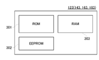
- FIG. 3 is an illustrative view showing one example of a configuration of a memory applied to the embodiment in FIG. 2;
- FIG. 5 is an illustrative view showing one example of a configuration of a failure information table created in the embodiment in FIG. 2;
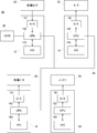
- FIG. 3 is an illustrative view showing one example of a connection state between an ECU and an external PC constituting the embodiment in FIG. 2;
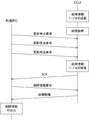
- FIG. 3 is an illustrative view showing one example of a connection state between the embodiment in FIG. 2 and an external PC; It is an illustration figure which shows an example of the communication protocol between external PC and ECU.
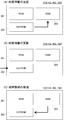
- (A) is an illustrative view showing an example of an operation for saving the failure information table on the EEPROM to the RAM
- (B) is an illustrative view showing an example of an operation for updating the failure information table on the EEPROM
- (C ) Is an illustrative view showing one example of an operation for repairing the failure information table on the EEPROM; It is a flowchart which shows a part of operation
- FIG. 11 is a flowchart showing still another portion of behavior of the CPU applied to the embodiment in FIG. 2; It is a flowchart which shows a part of operation
- the failure diagnosis apparatus of this embodiment is basically configured as follows.
- the diagnosis means 1 diagnoses a failure for each of one or more objects each time the power is turned on.
- the writing unit 2 writes the failure information indicating the failure detected by the diagnosis unit 1 in the memory 6 in such a manner that the failure information is stored regardless of power on / off.
- the accepting unit 3 accepts the repair request issued by the external device after the writing process by the writing unit 2.
- the repairing means 4 restores the storage state of the memory 6 to the state before the writing process by the writing means 2.
- the transmission unit 5 transmits the failure information stored in the memory 6 to the request source in response to the transmission request after the writing process by the writing unit 2.
- connection between the at least one object and the failure diagnosis device is released and the connection between the external device and the failure diagnosis device is established, the connection is released when the failure diagnosis device is turned on. Failure information indicating the failure of the object is additionally written in the memory 6.
- the storage state of the memory 6 is returned to the state before writing in response to the repair request given from the external device. Thereafter, when a transmission request is given from the external device, the failure information stored in the memory 6 at the time before writing is transmitted to the external device. Thereby, the reliability of the failure information referred to by the external device is maintained, and the diagnostic performance is improved.
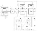
- the electric motorcycle 10 of this embodiment includes an EV controller 12, a motor control circuit 14, a meter control circuit 16 and a battery control circuit 18 which are connected to each other by a CAN bus 28.
- the EV controller 12 is formed by an A / D converter 121, a CPU 122, and a memory 123
- the motor control circuit 14 is formed by a D / A converter 141, a CPU 142, and a memory 143.
- the meter control circuit 16 is formed by a D / A converter 161, a CPU 162 and a memory 163
- the battery control circuit 18 is formed by a D / A converter 181, a CPU 182 and a memory 183.
- the various sensors 20 connected to the EV controller 12 detect the rotational operation of the motor 22, the output operation of the various meters 24, and the output voltage of the battery 26, as well as the operation state of an accelerator grip and a brake lever (not shown).
- the detection result is given to the CPU 122 via the A / D converter 121.
- the CPU 122 controls the motor control circuit 14, the meter control circuit 16, and the battery control circuit 18 in an integrated manner with reference to the given detection result.
- the CPU 142 provided in the motor control circuit 14 takes in a request issued by the EV controller 12 via the CAN bus 28 and gives a control signal corresponding to the taken-in request to the motor 22 through the D / A converter 141.
- the motor 22 performs a rotation operation in a manner according to the request of the EV controller 12.
- the CPU 162 provided in the meter control circuit 16 takes in a request issued by the EV controller 12 via the CAN bus 28 and gives a control signal corresponding to the taken-in request to various meters 24 through the D / A converter 161. .
- the various meters 24 perform a display operation in a manner according to the request of the EV controller 12.
- the CPU 182 provided in the battery control circuit 18 takes in a request issued by the EV controller 12 via the CAN bus 28 and gives a control signal corresponding to the taken-in request to the battery 26 through the D / A converter 181.
- the output of the battery 26 is adjusted according to the request of the EV controller 12.
- the rotation operation of the motor 22, the output operation of the various meters 24, and the output voltage of the battery 26 are detected by the various sensors 20, and the detection result is given to the EV controller 12. Thereby, feedback control of the motor 22, the various meters 24, and the battery 26 is realized.
- the EV controller 12, the motor control circuit 14, the meter control circuit 16, and the battery control circuit 18 are collectively referred to as an ECU (Electronic Control Unit) as necessary.
- each of memories 123, 143, 163, and 183 has ROM 301, EEPROM 302, and RAM 303.
- a ROM 301 provided in the memory 123 stores a control program for the CPU 122
- a ROM 301 provided in the memory 143 stores a control program for the CPU 142.
- the ROM 301 provided in the memory 163 stores a control program for the CPU 162
- the ROM 301 provided in the memory 183 stores a control program for the CPU 182.
- the EEPROM 302 provided in the memory 123 stores the failure information table TBL created by the failure diagnosis process of the CPU 122, and the EEPROM 302 provided in the memory 143 stores the failure information table TBL created by the failure diagnosis process of the CPU 142.
- the EEPROM 302 provided in the memory 163 stores a failure information table TBL created by the failure diagnosis process of the CPU 162, and the EEPROM 302 provided in the memory 183 stores the failure information table TBL created by the failure diagnosis process of the CPU 182. To do.
- the RAM 303 will be described later.
- the fault diagnosis process is executed as follows each time the power is turned on.
- the CPU 122 constituting the ECU 12 executes communication processing with each of the ECUs 14, 16 and 18 to create failure information.
- the generated failure information indicates “0” when the communication result does not match the error condition, and indicates “1” when the communication result matches the error condition.
- the CPU 142 constituting the ECU 14 executes communication processing with each of the ECUs 12, 16 and 18 to create failure information
- the CPU 162 constituting the ECU 16 executes communication processing with each of the ECUs 12, 14 and 18 and fails.
- the information is created, and the CPU 182 constituting the ECU 18 executes communication processing with each of the ECUs 12, 14, and 16 to create failure information.
- failure information table TBL has columns corresponding to the number of communication destination ECUs, and failure information created in the above-described manner is described in columns corresponding to communication destination ECMs.
- failure information table TBL provided in the ECU 12 failure information relating to the ECU 14 is described in the first column
- failure information relating to the ECU 16 is described in the second column
- failure information relating to the ECU 18 is described in the third column. Is done.
- failure information table TBL provided in the ECU 14 failure information relating to the ECU 12 is described in the first column
- failure information relating to the ECU 16 is described in the second column
- failure information relating to the ECU 18 is described in the third column. Is done.
- failure information relating to the ECU 12 is described in the first column
- failure information relating to the ECU 14 is described in the second column
- failure information relating to the ECU 18 is described in the third column. Is done.
- failure information relating to the ECU 12 is described in the first column
- failure information relating to the ECU 14 is described in the second column
- failure information relating to the ECU 16 is described in the third column. Is done.
- the failure information described in the failure information table TBL is read by the external PC 36 shown in FIG. 5 or 6 when the motorcycle 10 is inspected on the dealer side regularly or irregularly.
- the read failure information is displayed on the monitor 36d for maintenance (for example, firmware update) of the motorcycle 10.
- the failure information table TBL created by the failure diagnosis process at the subsequent power-on time reflects the communication error with the communication destination ECU.
- the ECU is connected to the external PC 36 via the connectors 30 to 32 and the I / F 34.
- the reliability of the failure information is ensured in the following manner by cooperation between the ECU and the external PC 36 connected to each other.
- the ECU that is powered on first executes a saving process of failure information table TBL.
- the failure information table TBL on the EEPROM 302 is saved in the RAM 303 as shown in FIG. Subsequently, the ECU executes the above-described failure diagnosis process.
- the failure information table TBL on the EEPROM 302 is updated with newly created failure information (see FIG. 8B).
- the external PC 36 repeatedly issues an update stop request to the ECU.
- the ECU accepts the issued update stop request after completion of the failure diagnosis process, and repairs the failure information table TBL on the EEPROM 302 with reference to the failure information table TBL saved in the RAM 303 (see FIG. 8C).
- an ACK signal is output from the ECU to the external PC 36.
- the external PC 36 recognizes the repair of the failure information table TBL by the ACK signal.
- the external PC 36 issues a failure information request to the ECU after receiving the ACK signal.
- the ECU returns the failure information described in the repaired failure information table TBL to the external PC 36 in response to the failure information request, and the external PC 36 displays the received failure information on the monitor 6d.
- Each of the CPUs 122, 142, 162, and 182 executes processing according to the flowcharts shown in FIGS. 9 to 11 when the power is turned on. Note that at least a part of the control program stored in the ROM 301 corresponds to this flowchart.
- step S1 the failure information table TBL stored in the EEPROM 302 is saved in the RAM 303, and in step S3, failure diagnosis processing is executed.
- the description of the failure information table TBL on the EEPROM 302 is updated with the failure information created by the failure diagnosis process.
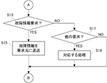
- step S5 it is determined whether an update stop request is given from the external PC 30 or another ECU.
- step S13 it is determined whether a failure information request is given from the external PC 30 or other ECU.
- step S17 it is determined. It is determined whether or not another request is given from the external PC 30 or another ECU.
- step S5 If the decision result in the step S5 is YES, the process advances to a step S7 so as to detect a difference in the description of the failure information table TBL between the RAM 303 and the EEPROM 302.
- step S9 the description of the failure information table TBL on the EEPROM 302 is modified in a limited manner so that the detected difference is eliminated. Specifically, a part of failure information corresponding to the difference is read from the failure information table TBL on the RAM 303, and the read failure information is overwritten on the corresponding column of the failure information table TBL on the EEPROM 302. As a result, the description in the failure information table TBL on the EEPROM 302 is returned to the description before the failure detection processing in step S3.
- step S11 an ACK signal is returned to the request source to notify that the repair of the failure information table TBL on the EEPROM 302 has been completed. When the return of the ACK signal is completed, the process returns to step S5.
- step S13 If the determination result of step S13 is YES, it will progress to step S15 and will return the failure information described in the failure information table TBL on EEPROM302 to a request origin. If the determination result of step S17 is YES, the corresponding process is executed in step S19. When the process of step S15 or S19 is completed, the process returns to step S5.
- the ECUs 14, 16 and 18 receive an update stop request or failure information request from the external PC 36 via the ECU 12, and store them in the failure information table TBL. The described failure information is returned to the external PC 36 via the ECU 12.
- the CPU 122 provided in the ECU 12 forwards the update stop request and the failure information request sent from the external PC 36 to the ECU 14, 16 or 18, or the failure information sent from the ECU 14, 16 or 18 to the external PC 36.
- the forwarding process is executed in steps S17 to S19.
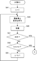
- step S3 The failure diagnosis process in step S3 shown in FIG. 9 is executed according to a subroutine shown in FIG.
- the variable K is set to “1”
- step S23 communication processing is executed with the Kth ECU.
- step S25 it is determined whether or not the result of the communication process matches an error condition. If the determination result is YES, the process proceeds to step S27. If the determination result is NO, the process proceeds to step S29.
- step S27 the failure information indicating “1” is described in the Kth column of the failure information table TBL on the EEPROM 302.
- step S29 failure information indicating “0” is described in the Kth column of the failure information table TBL on the EEPROM 302.
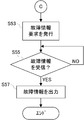
- the CPU 36p provided in the external PC 36 executes processing according to the flowcharts shown in FIGS. 12 to 13 when the motorcycle 10 or a single ECU is connected.
- a control program corresponding to these flowcharts is stored in the memory 36m.
- step S41 the variable L is set to “1”, an update stop request is issued in step S43, and a standby process for a predetermined time is executed in step S45.
- step S47 it is determined whether or not an ACK signal is returned.
- the ECMs 12 to 18 diagnose failures of other ECMs (S21 to S25, S31 to S33), and failure information indicating failures or errors detected thereby. Is written in the failure information table TBL on the EEPROM 302 (S27 to S29). The failure information is stored regardless of power on / off.
- the ECMs 12 to 18 also accept the update stop request issued by the external PC 36 after the failure information writing process (S5), and restore the failure information table TBL on the EEPROM 302 to the state before the failure information writing process (S1). , S7 ⁇ S9).
- the failure information described in the repaired failure information table TBL is returned to the external PC 36 in response to a subsequent failure information request (S13 to S15).
- failure information indicating the failure of the other ECU with which the connection has been released is displayed. It is additionally written in the failure information table TBL.
- the storage state of the failure information table TBL is returned to the state before writing in response to the update stop request given from the external PC 36. Thereafter, when a failure information request is given from the external PC 36, the failure information stored in the failure information table TBL at the time before writing is transmitted to the external PC 36. Thereby, the reliability of the failure information referred to by the external PC 36 is maintained, and the diagnostic performance is improved.
- the failure information table TBL on the EEPROM 302 is saved in the RAM 303.
- the failure information table TBL may be saved to a memory or a hard disk provided in the external PC 36.
- an electric motorcycle is assumed.
- the present invention can be applied to an electric four-wheeled vehicle, and can also be applied to a hybrid vehicle.
- another ECU is assumed as a diagnosis target.
- at least one of various sensors 20, motors 22, various meters 24, and a battery 26 may be added to the diagnosis target.
- the failure diagnosis process is executed only when the power is turned on, but the failure diagnosis process may be repeatedly executed during traveling.
- the diagnosis time is preferably assigned to the failure information.
Landscapes
- Physics & Mathematics (AREA)
- General Physics & Mathematics (AREA)
- Debugging And Monitoring (AREA)
Abstract
ECM12~18は、電源が投入される毎に他のECMについて故障を診断し、これによって検知された故障を示す故障情報をメモリ123~183に形成された故障情報テーブルに書き込む。故障情報は、電源の投入/遮断に関係なく保存される。ECM12~18はまた、外部PC36によって発行された更新停止要求を故障情報の書き込み処理の後に受け付け、故障情報テーブルTBLを故障情報の書き込み処理の前の状態に修復する。修復された故障情報テーブルTBLに記述された故障情報は、その後の故障情報要求に応答して外部PC36に返送される。
Description
この発明は、故障診断装置に関し、特に制御すべき1または2以上の対象物の各々について電源が投入される毎に故障ないしエラーを診断する、故障診断装置に関する。
この種の装置の一例が、特許文献1に開示されている。この背景技術によれば、主制御部,操作表示制御部,通信制御部,画像処理制御部および記憶媒体制御部の各々は、起動時に自己診断を実行する。ただし、自己診断の内容は、起動条件に応じて変更される。これによって、ユーザの使用目的と起動時に画像処理装置がクリアすべき条件との不整合を解消することができる。
しかし、背景技術では、各制御部と診断対象との接続がユーザによって意図的に解除されることや、このような接続解除に起因する診断結果の信頼性の低下を想定しておらず、診断性能に限界がある。
それゆえに、この発明の主たる目的は、診断性能を高めることができる、故障診断装置を提供することである。
この発明に従う故障診断装置は、次のものを備える:電源が投入される毎に1または2以上の対象物の各々について故障を診断する診断手段;診断手段によって検知された故障を示す故障情報を電源の投入/遮断に関係なく保存される態様でメモリに書き込む書き込み手段;外部装置によって発行された修復要求を書き込み手段による書き込み処理の後に受け付ける受け付け手段;受け付け手段によって受け付けられた修復要求に応答してメモリの保存状態を書き込み手段による書き込み処理の前の状態に修復する修復手段;およびメモリに保存された故障情報を書き込み手段による書き込み処理の後の送信要求に応答して要求元に送信する送信手段を備える。
好ましくは、修復手段は、メモリに保存された故障情報を書き込み手段による書き込み処理に先立って退避させる退避手段、および退避手段によって退避された故障情報を修復要求に応答してメモリに上書きする上書き手段を含む。
さらに好ましくは、修復手段は退避手段によって退避された故障情報と書き込み手段によって書き込まれた故障情報との相違を検出する検出手段をさらに含み、上書き手段は検出手段によって検出された相違に対応して限定的に上書きを実行する。
好ましくは、上述の故障診断装置は電気自動車に設けられる。
この発明に従う故障診断プログラムは、故障診断装置のプロセッサによって実行されるときに非一時的な記録媒体に記録される故障診断プログラムであって、次のステップを故障診断装置に実行させる:電源が投入される毎に1または2以上の対象物の各々について故障を診断する診断ステップ;診断ステップによって検知された故障を示す故障情報を電源の投入/遮断に関係なく保存される態様でメモリに書き込む書き込みステップ;外部装置によって発行された修復要求を書き込みステップによる書き込み処理の後に受け付ける受け付けステップ;受け付けステップによって受け付けられた修復要求に応答してメモリの保存状態を書き込みステップによる書き込み処理の前の状態に修復する修復ステップ;およびメモリに保存された故障情報を書き込みステップによる書き込み処理の後の送信要求に応答して要求元に送信する送信ステップ。
この発明に従う故障診断方法は、故障診断装置によって実行される故障診断方法であって、つぎのものを備える:電源が投入される毎に1または2以上の対象物の各々について故障を診断する診断ステップ;診断ステップによって検知された故障を示す故障情報を電源の投入/遮断に関係なく保存される態様でメモリに書き込む書き込みステップ;外部装置によって発行された修復要求を書き込みステップによる書き込み処理の後に受け付ける受け付けステップ;受け付けステップによって受け付けられた修復要求に応答してメモリの保存状態を書き込みステップによる書き込み処理の前の状態に修復する修復ステップ;およびメモリに保存された故障情報を書き込みステップによる書き込み処理の後の送信要求に応答して要求元に送信する送信ステップ。
この発明によれば、少なくとも1つの対象物と故障診断装置との接続が解除され、かつ外部装置と故障診断装置との接続が確立された状態で、故障診断装置の電源が投入されると、接続が解除された対象物の故障を示す故障情報がメモリに追加的に書き込まれる。
ただし、メモリの保存状態は、外部装置から与えられた修復要求に応答して書き込み前の状態に戻される。その後に外部装置から送信要求が与えられると、書き込み前の時点でメモリに保存されている故障情報が外部装置に送信される。これによって、外部装置によって参照される故障情報の信頼性が維持され、診断性能の向上が図られる。
この発明の上述の目的,その他の目的,特徴および利点は、図面を参照して行う以下の実施例の詳細な説明から一層明らかとなろう。
図1を参照して、この実施例の故障診断装置は、基本的に次のように構成される。診断手段1は、電源が投入される毎に1または2以上の対象物の各々について故障を診断する。書き込み手段2は、診断手段1によって検知された故障を示す故障情報を電源の投入/遮断に関係なく保存される態様でメモリ6に書き込む。受け付け手段3は、外部装置によって発行された修復要求を書き込み手段2による書き込み処理の後に受け付ける。修復手段4は、受け付け手段3によって受け付けられた修復要求に応答してメモリ6の保存状態を書き込み手段2による書き込み処理の前の状態に修復する。送信手段5は、メモリ6に保存された故障情報を書き込み手段2による書き込み処理の後の送信要求に応答して要求元に送信する。
少なくとも1つの対象物と故障診断装置との接続が解除され、かつ外部装置と故障診断装置との接続が確立された状態で、故障診断装置の電源が投入されると、接続が解除された対象物の故障を示す故障情報がメモリ6に追加的に書き込まれる。
ただし、メモリ6の保存状態は、外部装置から与えられた修復要求に応答して書き込み前の状態に戻される。その後に外部装置から送信要求が与えられると、書き込み前の時点でメモリ6に保存されている故障情報が外部装置に送信される。これによって、外部装置によって参照される故障情報の信頼性が維持され、診断性能の向上が図られる。
図2を参照して、この実施例の電動二輪車10は、CANバス28によって互いに接続されたEVコントローラ12,モータ制御回路14,メータ制御回路16およびバッテリ制御回路18を含む。EVコントローラ12はA/D変換器121,CPU122およびメモリ123によって形成され、モータ制御回路14はD/A変換器141,CPU142およびメモリ143によって形成される。また、メータ制御回路16はD/A変換器161,CPU162およびメモリ163によって形成され、バッテリ制御回路18はD/A変換器181,CPU182およびメモリ183によって形成される。
EVコントローラ12に接続された各種センサ20は、モータ22の回転動作,各種メータ24の出力動作およびバッテリ26の出力電圧を検知するとともに、図示しないアクセルグリップおよびブレーキレバーの操作状態を検知する。検知結果は、A/D変換器121を介してCPU122に与えられる。CPU122は、与えられた検知結果を参照してモータ制御回路14,メータ制御回路16およびバッテリ制御回路18を統合的に制御する。
モータ制御回路14に設けられたCPU142は、EVコントローラ12によって発行された要求をCANバス28を介して取り込み、取り込まれた要求に対応する制御信号をD/A変換器141を通してモータ22に与える。モータ22は、EVコントローラ12の要求に従う態様で回転動作を実行する。
メータ制御回路16に設けられたCPU162は、EVコントローラ12によって発行された要求をCANバス28を介して取り込み、取り込まれた要求に対応する制御信号をD/A変換器161を通して各種メータ24に与える。各種メータ24は、EVコントローラ12の要求に従う態様で表示動作を実行する。
バッテリ制御回路18に設けられたCPU182は、EVコントローラ12によって発行された要求をCANバス28を介して取り込み、取り込まれた要求に対応する制御信号をD/A変換器181を通してバッテリ26に与える。バッテリ26の出力は、EVコントローラ12の要求に従って調整される。
上述のように、モータ22の回転動作,各種メータ24の出力動作およびバッテリ26の出力電圧は各種センサ20によって検知され、検知結果がEVコントローラ12に与えられる。これによって、モータ22,各種メータ24およびバッテリ26のフィードバック制御が実現される。
なお、以下では、EVコントローラ12,モータ制御回路14,メータ制御回路16およびバッテリ制御回路18を、必要に応じてECU(Electronic Control Unit)と総称する。
図3を参照して、メモリ123,143,163および183の各々は、ROM301,EEPROM302およびRAM303を有する。メモリ123に設けられたROM301はCPU122の制御プログラムを記憶し、メモリ143に設けられたROM301はCPU142の制御プログラムを記憶する。また、メモリ163に設けられたROM301はCPU162の制御プログラムを記憶し、メモリ183に設けられたROM301はCPU182の制御プログラムを記憶する。
メモリ123に設けられたEEPROM302はCPU122の故障診断処理によって作成された故障情報テーブルTBLを記憶し、メモリ143に設けられたEEPROM302はCPU142の故障診断処理によって作成された故障情報テーブルTBLを記憶する。また、メモリ163に設けられたEEPROM302はCPU162の故障診断処理によって作成された故障情報テーブルTBLを記憶し、メモリ183に設けられたEEPROM302はCPU182の故障診断処理によって作成された故障情報テーブルTBLを記憶する。なお、RAM303については後述する。
故障診断処理は、電源が投入される毎に以下の要領で実行される。ECU12を構成するCPU122は、ECU14,16および18の各々と通信処理を実行して故障情報を作成する。作成される故障情報は、通信結果がエラー条件に合致しないとき“0”を示し、通信結果がエラー条件に合致するとき“1”を示す。
同様に、ECU14を構成するCPU142はECU12,16および18の各々と通信処理を実行して故障情報を作成し、ECU16を構成するCPU162はECU12,14および18の各々と通信処理を実行して故障情報を作成し、そしてECU18を構成するCPU182はECU12,14および16の各々と通信処理を実行して故障情報を作成する。
図4を参照して、故障情報テーブルTBLは、通信先のECUの数に相当するカラムを有し、上述の要領で作成された故障情報は通信先のECMに対応するカラムに記述される。ECU12に設けられた故障情報テーブルTBLにおいては、ECU14に関する故障情報が1番目のカラムに記述され、ECU16に関する故障情報が2番目のカラムに記述され、そしてECU18に関する故障情報が3番目のカラムに記述される。ECU14に設けられた故障情報テーブルTBLにおいては、ECU12に関する故障情報が1番目のカラムに記述され、ECU16に関する故障情報が2番目のカラムに記述され、そしてECU18に関する故障情報が3番目のカラムに記述される。
ECU16に設けられた故障情報テーブルTBLにおいては、ECU12に関する故障情報が1番目のカラムに記述され、ECU14に関する故障情報が2番目のカラムに記述され、そしてECU18に関する故障情報が3番目のカラムに記述される。ECU18に設けられた故障情報テーブルTBLにおいては、ECU12に関する故障情報が1番目のカラムに記述され、ECU14に関する故障情報が2番目のカラムに記述され、そしてECU16に関する故障情報が3番目のカラムに記述される。
故障情報テーブルTBLにこうして記述された故障情報は、定期的または不定期で自動二輪車10をディーラ側で点検する際に、図5または図6に示す外部PC36によって読み出される。読み出された故障情報は、自動二輪車10のメンテナンス(たとえばファームウェアの更新)のためにモニタ36dに表示される。
ただし、外部PC36が自動二輪車10から取り外された単独のECUと接続された場合(図5参照)や、外部PC36が自動二輪車10と接続されたとしても、一部のECUが自動二輪車10から欠落している場合(図6参照)は、その後の電源投入時点の故障診断処理によって作成された故障情報テーブルTBLが、通信先のECUとの通信エラーを反映してしまう。なお、図5および図6のいずれにおいても、ECUはコネクタ30~32およびI/F34を介して外部PC36と接続される。
具体的には、図5に示すようにECU12が単独で外部PC36と接続されると、ECU12の故障情報テーブルTBLに記述された故障情報の全てが、電源投入に応答して“1”に更新される。また、図6に示すようにECU16が欠落した状態で自動二輪車10が外部PC36に接続されると、ECU12,14および18の故障情報テーブルTBLに記述された故障情報のうちECU16に対応する故障情報が、電源投入に応答して“1”に更新される。このようなタイミングでの故障情報の更新は、自動二輪車のメンテナンスに利用される故障情報の信頼性の低下を引き起こす。
そこで、この実施例では、互いに接続されたECUと外部PC36との連携によって、以下の要領で故障情報の信頼性を確保するようにしている。図7を参照して、電源が投入されたECUは、まず故障情報テーブルTBLの退避処理を実行する。EEPROM302上の故障情報テーブルTBLは、図8(A)に示す要領でRAM303に退避される。ECUは続いて、上述した故障診断処理を実行する。EEPROM302上の故障情報テーブルTBLは、新規に作成された故障情報によって更新される(図8(B)参照)。
一方、外部PC36は、更新停止要求をECUに向けて繰り返し発行する。ECUは、発行された更新停止要求を故障診断処理の完了後に受け付け、RAM303に退避された故障情報テーブルTBLを参照してEEPROM302上の故障情報テーブルTBLを修復する(図8(C)参照)。修復が完了すると、ECUから外部PC36に向けてACK信号が出力される。外部PC36は、ACK信号によって故障情報テーブルTBLの修復を認識する。
なお、外部PC36は、ACK信号を受信した後、故障情報要求をECUに向けて発行する。ECUは、修復された故障情報テーブルTBLに記述された故障情報を故障情報要求に応答して外部PC36に返送し、外部PC36は受信した故障情報をモニタ6dに表示する。
CPU122,142,162および182の各々は、電源が投入されたとき図9~図11に示すフロー図に従う処理を実行する。なお、ROM301に記憶された制御プログラムの少なくとも一部が、このフロー図に対応する。
ステップS1ではEEPROM302に保存された故障情報テーブルTBLをRAM303に退避させ、ステップS3では故障診断処理を実行する。EEPROM302上の故障情報テーブルTBLの記述は、故障診断処理によって作成された故障情報によって更新される。ステップS5では外部PC30または他のECUから更新停止要求が与えられたか否かを判別し、ステップS13では故障情報要求が外部PC30または他のECUから与えられたか否かを判別し、そしてステップS17では他の要求が外部PC30または他のECUから与えられたか否かを判別する。
ステップS5の判別結果がYESであればステップS7に進み、RAM303とEEPROM302との間での故障情報テーブルTBLの記述の相違を検出する。ステップS9では、検出された相違が解消されるようにEEPROM302上の故障情報テーブルTBLの記述を限定的に修正する。具体的には、相違に相当する一部の故障情報をRAM303上の故障情報テーブルTBLから読み出し、読み出された故障情報をEEPROM302上の故障情報テーブルTBLの対応するカラムに上書きする。これによって、EEPROM302上の故障情報テーブルTBLの記述がステップS3の故障検知処理の前の記述に戻される。ステップS11では、EEPROM302上の故障情報テーブルTBLの修復が完了したことを通知するべく、ACK信号を要求元に返送する。ACK信号の返送が完了すると、ステップS5に戻る。
ステップS13の判別結果がYESであればステップS15に進み、EEPROM302上の故障情報テーブルTBLに記述された故障情報を要求元に返送する。また、ステップS17の判別結果がYESであれば、対応する処理をステップS19で実行する。ステップS15またはS19の処理が完了すると、ステップS5に戻る。
なお、図6に示すように外部PC36がコネクタ30に接続された場合、ECU14,16および18は、外部PC36からの更新停止要求または故障情報要求をECU12を介して受信し、故障情報テーブルTBLに記述された故障情報をECU12を介して外部PC36に返送する。
このとき、ECU12に設けられたCPU122は、外部PC36からECU14,16または18に宛てられた更新停止要求および故障情報要求の回送処理、或いはECU14,16または18から外部PC36に宛てられた故障情報の回送処理をステップS17~S19で実行する。
図9に示すステップS3の故障診断処理は、図11に示すサブルーチンに従って実行される。まずステップS21で変数Kを“1”に設定し、ステップS23でK番目のECUとの間で通信処理を実行する。ステップS25では通信処理の結果がエラー条件に合致するか否かを判別し、判別結果がYESであればステップS27に進む一方、判別結果がNOであればステップS29に進む。
ステップS27では、“1”を示す故障情報をEEPROM302上の故障情報テーブルTBLのK番目のカラムに記述する。ステップS29では、“0”を示す故障情報をEEPROM302上の故障情報テーブルTBLのK番目のカラムに記述する。ステップS31では変数Kが最大値Kmax(=3)に達したか否かを判別し、判別結果がNOであればステップS33で変数KをインクリメントしてからステップS23に戻る一方、判別結果がYESであれば上階層のルーチンに復帰する。
外部PC36に設けられたCPU36pは、自動二輪車10または単独のECUが接続されたとき、図12~図13に示すフロー図に従う処理を実行する。なお、これらのフロー図に対応する制御プログラムは、メモリ36mに記憶される。
ステップS41では変数Lを“1”に設定し、ステップS43では更新停止要求を発行し、そしてステップS45では既定時間の待機処理を実行する。ステップS47ではACK信号が返送されたか否かを判別し、ステップS49では変数Lが最大値Lmax(=10)に達したか否かを判別する。ステップS47の判別結果およびステップS49の判別結果のいずれもがNOであれば、ステップS51で変数Lをインクリメントし、その後にステップS43に戻る。ステップS47の判別結果およびステップS49の判別結果のいずれか一方がYESであれば、ステップS53で故障情報要求を発行し、ステップS55では故障情報が返送されたか否かを判別する。判別結果がNOからYESに更新されるとステップS57に進み、返送された故障情報をモニタ30dに表示する。
以上の説明から分かるように、ECM12~18は、電源が投入される毎に他のECMについて故障を診断し(S21~S25,S31~S33)、これによって検知された故障ないしエラーを示す故障情報をEEPROM302上の故障情報テーブルTBLに書き込む(S27~S29)。故障情報は、電源の投入/遮断に関係なく保存される。ECM12~18はまた、外部PC36によって発行された更新停止要求を故障情報の書き込み処理の後に受け付け(S5)、EEPROM302上の故障情報テーブルTBLを故障情報の書き込み処理の前の状態に修復する(S1,S7~S9)。修復された故障情報テーブルTBLに記述された故障情報は、その後の故障情報要求に応答して外部PC36に返送される(S13~S15)。
他の少なくとも1つのECUとの接続が解除され、かつ外部PC36との接続が確立された状態で、ECUの電源が投入されると、接続が解除された他のECUの故障を示す故障情報が故障情報テーブルTBLに追加的に書き込まれる。
ただし、故障情報テーブルTBLの保存状態は、外部PC36から与えられた更新停止要求に応答して書き込み前の状態に戻される。その後に外部PC36から故障情報要求が与えられると、書き込み前の時点で故障情報テーブルTBLに保存されている故障情報が外部PC36に送信される。これによって、外部PC36によって参照される故障情報の信頼性が維持され、診断性能の向上が図られる。
なお、この実施例では、EEPROM302上の故障情報テーブルTBLをRAM303に退避させるようにしているが、故障情報テーブルTBLの退避先は外部PC36に設けられたメモリないしハードディスクであってもよい。さらに、この実施例では、電動二輪車を想定しているが、この発明は電動四輪車にも適用できるし、さらにハイブリッド型の自動車にも適用できる。
また、この実施例では、他のECUを診断対象として想定しているが、各種センサ20,モータ22,各種メータ24およびバッテリ26の少なくとも1つを診断対象に追加するようにしてもよい。
さらに、この実施例では、電源が投入された時点でのみ故障診断処理を実行するようにしているが、故障診断処理は走行中に繰り返し実行するようにしてもよい。この場合、好ましくは、診断時刻が故障情報に割り当てられる。これによって、走行中に発生した故障やエラーを容易に認識することができる。
この発明が詳細に説明され図示されたが、それは単なる図解および一例として用いたものであり、限定であると解されるべきではないことは明らかであり、この発明の精神および範囲は添付されたクレームの文言によってのみ限定される。
10 …電動二輪車
12 …EVコントローラ
14 …モータ制御回路
16 …メータ制御回路
18 …バッテリ制御回路
122,142,162,182 …CPU
302 …EEPROM
303 …RAM
12 …EVコントローラ
14 …モータ制御回路
16 …メータ制御回路
18 …バッテリ制御回路
122,142,162,182 …CPU
302 …EEPROM
303 …RAM
Claims (6)
- 故障診断装置であって、次のものを備える:
電源が投入される毎に1または2以上の対象物の各々について故障を診断する診断手段;
前記診断手段によって検知された故障を示す故障情報を前記電源の投入/遮断に関係なく保存される態様でメモリに書き込む書き込み手段;
外部装置によって発行された修復要求を前記書き込み手段による書き込み処理の後に受け付ける受け付け手段;
前記受け付け手段によって受け付けられた修復要求に応答して前記メモリの保存状態を前記書き込み手段による書き込み処理の前の状態に修復する修復手段;および
前記メモリに保存された故障情報を前記書き込み手段による書き込み処理の後の送信要求に応答して要求元に送信する送信手段。 - クレーム1に従属する故障診断装置であって、前記修復手段は、前記メモリに保存された故障情報を前記書き込み手段による書き込み処理に先立って退避させる退避手段、および前記退避手段によって退避された故障情報を前記修復要求に応答して前記メモリに上書きする上書き手段を含む。
- クレーム2に従属する故障診断装置であって、前記修復手段は前記退避手段によって退避された故障情報と前記書き込み手段によって書き込まれた故障情報との相違を検出する検出手段をさらに含み、
前記上書き手段は前記検出手段によって検出された相違に対応して限定的に上書きを実行する。 - クレーム1に従属する故障診断装置を備える、電気自動車。
- 故障診断装置のプロセッサによって実行されるときに非一時的な記録媒体に記録される故障診断プログラムであって、次のステップを故障診断装置に実行させる:
電源が投入される毎に1または2以上の対象物の各々について故障を診断する診断ステップ;
前記診断ステップによって検知された故障を示す故障情報を前記電源の投入/遮断に関係なく保存される態様でメモリに書き込む書き込みステップ;
外部装置によって発行された修復要求を前記書き込みステップによる書き込み処理の後に受け付ける受け付けステップ;
前記受け付けステップによって受け付けられた修復要求に応答して前記メモリの保存状態を前記書き込みステップによる書き込み処理の前の状態に修復する修復ステップ;および
前記メモリに保存された故障情報を前記書き込みステップによる書き込み処理の後の送信要求に応答して要求元に送信する送信ステップ。 - 故障診断装置によって実行される故障診断方法であって、次のものを備える:
電源が投入される毎に1または2以上の対象物の各々について故障を診断する診断ステップ;
前記診断ステップによって検知された故障を示す故障情報を前記電源の投入/遮断に関係なく保存される態様でメモリに書き込む書き込みステップ;
外部装置によって発行された修復要求を前記書き込みステップによる書き込み処理の後に受け付ける受け付けステップ;
前記受け付けステップによって受け付けられた修復要求に応答して前記メモリの保存状態を前記書き込みステップによる書き込み処理の前の状態に修復する修復ステップ;および
前記メモリに保存された故障情報を前記書き込みステップによる書き込み処理の後の送信要求に応答して要求元に送信する送信ステップ。
Priority Applications (1)
| Application Number | Priority Date | Filing Date | Title |
|---|---|---|---|
| JP2012542274A JPWO2012111493A1 (ja) | 2011-02-18 | 2012-02-08 | 故障診断装置 |
Applications Claiming Priority (2)
| Application Number | Priority Date | Filing Date | Title |
|---|---|---|---|
| JP2011033105 | 2011-02-18 | ||
| JP2011-033105 | 2011-02-18 |
Publications (1)
| Publication Number | Publication Date |
|---|---|
| WO2012111493A1 true WO2012111493A1 (ja) | 2012-08-23 |
Family
ID=46672419
Family Applications (1)
| Application Number | Title | Priority Date | Filing Date |
|---|---|---|---|
| PCT/JP2012/052802 Ceased WO2012111493A1 (ja) | 2011-02-18 | 2012-02-08 | 故障診断装置 |
Country Status (2)
| Country | Link |
|---|---|
| JP (1) | JPWO2012111493A1 (ja) |
| WO (1) | WO2012111493A1 (ja) |
Cited By (1)
| Publication number | Priority date | Publication date | Assignee | Title |
|---|---|---|---|---|
| US10351127B2 (en) * | 2013-12-25 | 2019-07-16 | Denso Corporation | Vehicle diagnosis system and method |
Citations (3)
| Publication number | Priority date | Publication date | Assignee | Title |
|---|---|---|---|---|
| JPH01267739A (ja) * | 1988-04-20 | 1989-10-25 | Hitachi Ltd | デイジタル演算処理装置 |
| JPH09170931A (ja) * | 1995-12-21 | 1997-06-30 | Denshi Giken:Kk | 自己診断機能付データ収録装置 |
| JPH1021107A (ja) * | 1996-06-27 | 1998-01-23 | Nec Home Electron Ltd | マイクロコンピュータ装置 |
-
2012
- 2012-02-08 JP JP2012542274A patent/JPWO2012111493A1/ja active Pending
- 2012-02-08 WO PCT/JP2012/052802 patent/WO2012111493A1/ja not_active Ceased
Patent Citations (3)
| Publication number | Priority date | Publication date | Assignee | Title |
|---|---|---|---|---|
| JPH01267739A (ja) * | 1988-04-20 | 1989-10-25 | Hitachi Ltd | デイジタル演算処理装置 |
| JPH09170931A (ja) * | 1995-12-21 | 1997-06-30 | Denshi Giken:Kk | 自己診断機能付データ収録装置 |
| JPH1021107A (ja) * | 1996-06-27 | 1998-01-23 | Nec Home Electron Ltd | マイクロコンピュータ装置 |
Cited By (1)
| Publication number | Priority date | Publication date | Assignee | Title |
|---|---|---|---|---|
| US10351127B2 (en) * | 2013-12-25 | 2019-07-16 | Denso Corporation | Vehicle diagnosis system and method |
Also Published As
| Publication number | Publication date |
|---|---|
| JPWO2012111493A1 (ja) | 2014-07-03 |
Similar Documents
| Publication | Publication Date | Title |
|---|---|---|
| US11467818B2 (en) | Software update device, software update method, and software update system | |
| JP4509602B2 (ja) | オペレータ側システムおよびモードファイルの特定方法 | |
| CN105109427B (zh) | 一种汽车里程备份方法 | |
| CN116100996B (zh) | 一种车辆胎压控制方法、装置及设备 | |
| JP2012103911A (ja) | 情報記録装置 | |
| CN105453141B (zh) | 用于检测电子系统中的故障的设备和方法 | |
| CN115384533A (zh) | 一种智能驾驶域控制器、车辆控制方法以及车辆 | |
| CN103135525A (zh) | 一种整车参数配置方法 | |
| CN104276106A (zh) | 用于混合动力/纯电动车辆的加速踏板零点值故障诊断方法 | |
| KR101673776B1 (ko) | 자동차용 헤드유닛 및 카메라 유닛의 고장 진단 방법 | |
| CN114385421A (zh) | 数据存储方法、装置、电子设备及存储介质 | |
| WO2017201952A1 (zh) | 一种存储信息的系统和装置 | |
| JP4509603B2 (ja) | 制御ユニットおよびデータ送信方法 | |
| CN202110528U (zh) | 一种ecu嵌入式软件刷新和下载编程的系统 | |
| JPWO2012111493A1 (ja) | 故障診断装置 | |
| CN113253701B (zh) | 车辆远程诊断系统及方法 | |
| US8229620B2 (en) | Method for model-based diagnosis of a mechatronic system | |
| JP2014221608A (ja) | 車両の電子制御装置 | |
| JP2005014743A (ja) | 車両用故障部品探知装置 | |
| CN103649861A (zh) | 在车辆的故障存储器中的故障登记 | |
| JP7205245B2 (ja) | 電子制御装置 | |
| JP2009519420A (ja) | 装置の動作故障に関するデータの保存方法 | |
| CN109946094A (zh) | 机动车检测控制仪表及其控制电路、控制方法 | |
| JP5182583B2 (ja) | 車両用通信制御装置 | |
| CN101278321A (zh) | 用于改进车辆内可能故障的诊断的方法 |
Legal Events
| Date | Code | Title | Description |
|---|---|---|---|
| WWE | Wipo information: entry into national phase |
Ref document number: 2012542274 Country of ref document: JP |
|
| 121 | Ep: the epo has been informed by wipo that ep was designated in this application |
Ref document number: 12746951 Country of ref document: EP Kind code of ref document: A1 |
|
| NENP | Non-entry into the national phase |
Ref country code: DE |
|
| 122 | Ep: pct application non-entry in european phase |
Ref document number: 12746951 Country of ref document: EP Kind code of ref document: A1 |