WO2012111207A1 - 複合紙葉類供給装置、複合紙葉類供給方法及び、郵便機械 - Google Patents
複合紙葉類供給装置、複合紙葉類供給方法及び、郵便機械 Download PDFInfo
- Publication number
- WO2012111207A1 WO2012111207A1 PCT/JP2011/076749 JP2011076749W WO2012111207A1 WO 2012111207 A1 WO2012111207 A1 WO 2012111207A1 JP 2011076749 W JP2011076749 W JP 2011076749W WO 2012111207 A1 WO2012111207 A1 WO 2012111207A1
- Authority
- WO
- WIPO (PCT)
- Prior art keywords
- envelope
- unit
- suction
- postal
- Prior art date
Links
Images


Classifications
-
- B—PERFORMING OPERATIONS; TRANSPORTING
- B65—CONVEYING; PACKING; STORING; HANDLING THIN OR FILAMENTARY MATERIAL
- B65H—HANDLING THIN OR FILAMENTARY MATERIAL, e.g. SHEETS, WEBS, CABLES
- B65H3/00—Separating articles from piles
- B65H3/08—Separating articles from piles using pneumatic force
- B65H3/12—Suction bands, belts, or tables moving relatively to the pile
- B65H3/124—Suction bands or belts
-
- B—PERFORMING OPERATIONS; TRANSPORTING
- B65—CONVEYING; PACKING; STORING; HANDLING THIN OR FILAMENTARY MATERIAL
- B65H—HANDLING THIN OR FILAMENTARY MATERIAL, e.g. SHEETS, WEBS, CABLES
- B65H2511/00—Dimensions; Position; Numbers; Identification; Occurrences
- B65H2511/40—Identification
- B65H2511/416—Identification of material
-
- B—PERFORMING OPERATIONS; TRANSPORTING
- B65—CONVEYING; PACKING; STORING; HANDLING THIN OR FILAMENTARY MATERIAL
- B65H—HANDLING THIN OR FILAMENTARY MATERIAL, e.g. SHEETS, WEBS, CABLES
- B65H2513/00—Dynamic entities; Timing aspects
- B65H2513/10—Speed
-
- B—PERFORMING OPERATIONS; TRANSPORTING
- B65—CONVEYING; PACKING; STORING; HANDLING THIN OR FILAMENTARY MATERIAL
- B65H—HANDLING THIN OR FILAMENTARY MATERIAL, e.g. SHEETS, WEBS, CABLES
- B65H2701/00—Handled material; Storage means
- B65H2701/10—Handled articles or webs
- B65H2701/19—Specific article or web
- B65H2701/1916—Envelopes and articles of mail
Definitions
- the present invention relates to a composite paper sheet supply apparatus, a composite paper sheet supply method, and a postal machine that continuously separate and send a plurality of postal items of different envelope types.
- the exterior of the mail is referred to as an envelope body
- the paper envelope body is referred to as a standard envelope body
- the envelope body such as vinyl that is weaker than paper
- a soft envelope body If the separation processing conditions set for standard envelopes are applied as they are to postal mails of soft envelopes, the soft envelopes are weaker than standard envelopes, so damage such as wrinkles and tears can easily occur . Therefore, in order to continuously separate and sort a bundle of mail pieces (hereinafter referred to as a mail bundle) in which standard envelope bodies and soft envelope bodies are mixed, the mail pieces to be separated are soft envelope bodies. Therefore, it is necessary to perform a separate sending process different from the standard envelope. That is, separation processing according to the type of envelope is required.
- Japanese Patent Application Laid-Open No. 10-134225 discloses a technique for continuously distinguishing banknotes in different states. That is, when a banknote that may be damaged is conveyed at a high speed, troubles such as paper jams and poor stacking tend to occur. Therefore, when a banknote that is being transported is provided and a banknote being transported is a specific denomination banknote that is easily damaged, the controller decelerates the transport motor and the separation and accumulation motor, and follows. The bill feeding speed is slowed down. This prevents troubles such as paper jams and poor stacking when the banknotes are conveyed at high speed.
- the banknotes targeted by the above-mentioned Japanese Patent Application Laid-Open No. 10-134225 are known in size and thickness, but in the case of postal items, the size, thickness, and weight are different from each other. In some cases, mail bundles containing different types of envelopes cannot be separated continuously. Therefore, the main object of the present invention is to provide a composite paper sheet supply device and composite paper that can perform separation and sending processing without damaging the postal matter even if it is a postal bundle containing different types of envelopes. It is to provide a leaf supply method and a postal machine.
- a bundle of postal items including a standard envelope postal item having a standard waist strength and a soft envelope postal item having a lower waist strength has been conveyed. It includes a type detector that detects the envelope type of the first mail piece of the mail bundle, and a suction belt that rotates at a predetermined speed. Includes a suction section that separates from the mail piece, a pair of pickup rollers that rotate at a predetermined speed, a pick-up section that grips and sends out the first mail piece separated by the suction section, and the envelope type of the first mail piece based on the type signal A control unit that determines and controls the rotation speed of the suction unit and the pickup unit.
- the envelope type of the first mail piece of the mail bundle in which the mail bundle including the mail piece of the standard envelope with the waist strength and the mail of the soft envelope softer than the standard envelope has been conveyed Detection procedure, a suction procedure that separates the first mail piece from other mail pieces by the frictional force when the first mail piece contacts the suction belt rotating at a predetermined speed, and the first mail separated by the suction procedure.
- a pick-up procedure for gripping and sending out an article by a pair of pick-up rollers rotating at a predetermined speed, and a control procedure for controlling the rotational speed of the suction procedure and the pick-up procedure by judging the envelope type of the first mail piece based on the type signal It is characterized by including these.
- the type of envelope body is detected and control is performed according to the type of envelope body, even a mail bundle containing different types of envelopes is damaged.
- the separation and transmission process can be performed without giving
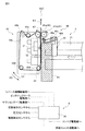
- FIG. 1 is a partial side view of a composite paper sheet supply apparatus in a mail machine according to an embodiment of the present invention.
- FIG. 2 is a perspective view of the pickup roller according to the embodiment.
- FIG. 3 is a partial side view of the composite paper sheet supply apparatus when the separation unit is retracted from the mail according to the embodiment.
- FIG. 4 is a flowchart of the composite paper sheet supply apparatus of the mail machine according to the embodiment.
- FIG. 1 is a partial side view of a composite paper sheet feeder 4 of a mail machine 2 according to the present invention.
- the composite paper sheet supply apparatus 4 includes a transport unit 6, a control unit 8, a supply unit 10, and a separation unit 46.
- a bundle of postal items conveyed by the conveyor 21 is a postal piece bundle K1, a top postal matter that separates the postal matter bundle K1 from the postal piece bundle K1, and a postal matter that is separated and sent out. It is described as K3.
- the mail bundle K1 contains a mixture of soft envelopes and standard envelopes.
- an envelope of a vinyl product will be described as an example of the flexible envelope, but the present invention is not limited to the vinyl product.
- the control unit 8 includes a state detector 31, a type detector 32, a pressure detector 33, and a control unit 34.
- the control unit 34 controls the transport unit 6 and the supply unit 10 based on the detection signal from the state detector 31, the type signal from the type detector 32, and the pressure signal from the pressure detector 33.
- the state detector 31 detects the presence or absence of the head mail K2, and outputs the detection result to the control unit 34 as a detection signal.
- the type detector 32 detects the reflected light from the head mail K2, and outputs the detection result to the control unit 34 as a type signal.
- the pressure detector 33 is disposed on the back side (the back side in FIG. 1) of the supply unit 10 and detects the force with which the backup plate 22 presses the mail bundle K1 against the supply unit 10 side.
- the transport unit 6 includes a conveyor 21 and a backup plate 22.
- One end of the conveyor 21 extends to the supply unit 10, and conveys the mail bundle K ⁇ b> 1 to the supply unit 10.
- the backup plate 22 operates corresponding to the driving state of the conveyor 21.
- the control unit 34 stops the conveyor 21 and operates the backup plate 22.
- the mail bundle K1 conveyed by the conveyor 21 is pressed against the supply unit 10 side.
- the supply unit 10 includes a pickup unit 41 and a suction unit 43.
- the pickup unit 41 includes a pair of pickup rollers 41a and 41b and a pickup roller driving unit (not shown) that rotationally drives the pickup rollers 41a and 41b.
- the suction unit 43 includes a tension roller 43a, a suction roller 43b, a suction belt 43c, a driven roller 43d, a suction roller driving unit (not shown) that rotationally drives the suction roller 43b, and a supply unit swing that swings the supply unit 10. Part (not shown).
- the pickup roller driving unit and the suction roller driving unit include a driving source such as a servo motor, and the rotation speed and the like are controlled by the control unit 34.
- the pickup roller 41a is a two-stage roller as shown in FIG.
- the second roller portion 47c that is freely inserted and rotated.
- the first roller portion 47b faces the pickup roller 41b at a predetermined interval (including the case where it contacts). At least one of the pickup roller 41a or the pickup roller 41b rotates by receiving rotational power from a pickup roller driving unit (not shown). As a result, the pickup unit 41 grips and sends the postal matter conveyed by the conveyor 21.
- the suction belt 43c is stretched around a pickup roller 41a, a suction roller 43b, a tension roller 43a, and a driven roller 43d, and is formed of a material having a high friction coefficient such as rubber.
- the tension roller 43a adjusts the tension of the suction belt 43c so that the frictional force applied to the leading postal matter K2 does not fluctuate.
- the suction belt 43c rotates, the leading postal matter K2 moves in the direction of rotation of the suction belt 43c by the frictional force with the suction belt 43c, and is separated from the other postal bundles K1. Thereafter, the head mail K2 is sandwiched and picked up by the pickup rollers 41a and 41b.
- the supply unit swinging section swings the supply unit 10 in the direction of arrow D1 (clockwise direction) or arrow D2 (counterclockwise direction) in FIG. Move.
- the pressure received by the first mail piece K2 is the origin of the frictional force that the first mail piece K2 receives from the suction belt 43c and the other mail bundle K1.
- the direction of the frictional force received from the suction belt 43c and the frictional force received from the other mail bundle K1 are opposite. For this reason, if a large pressure is applied when the top postal matter K2 is a flexible envelope, the top postal matter K2 may be damaged by a frictional force such as wrinkles and breakage.
- the pressure detector 33 detects the force applied to the leading postal matter K2, and the control unit 34 drives the supply unit swinging unit so that the pressure signal becomes equal to or lower than the pressure reference value, and causes the supply unit 10 to move.
- Rock That is, when the control unit 34 determines that a pressure larger than the pressure reference value is acting on the first mail piece K2, the control unit 34 rotates the supply unit 10 in the direction of the arrow D1 in FIG. Make it smaller. On the other hand, when the control unit 34 determines that a force smaller than the pressure reference value is acting on the first mail piece K2, the control unit 34 rotates the supply unit 10 in the direction of the arrow D2 to increase the pressure applied to the first mail piece K2. .
- the separation unit 46 includes a separation roller 46a, a plurality of rollers 46b, a separation belt 46c stretched over the rollers 46a and 46b, a separation unit position adjusting unit (not shown), and a separation unit driving unit (not shown).
- the separation unit driving unit rotationally drives at least one of the plurality of rollers 46a and 46b.
- the separation belt 46c rotates in the direction opposite to the rotation direction of the suction belt 43c.
- the force in the opposite direction is the separation force.
- the separation unit position adjustment unit adjusts the position of the separation roller 46a with respect to the suction belt 43c.
- the separation belt 46c is in contact with the other mail bundle K1 that has moved together with the leading mail K2. Push back the mail bundle K1. Therefore, only the head mail K2 can be separated. At this time, if the separation belt 46c is strongly pressed against the suction belt 43c, a large separation force acts on the leading postal matter K2. This large separation force may cause wrinkles or damage to the front mail piece K2. In particular, when the first postal matter K2 is a flexible envelope, wrinkles or breakage easily occurs.
- FIG. 3 is a partial side view of the composite sheet supply device 4 of the supply unit 10 when the separation unit 46 is retracted from the head mail K2.
- the separation belt 46c is the first mail.
- the separation unit 46 is moved backward so as not to hit the object K2 strongly.
- the separation force acting on the first mail piece K2 is reduced, so that the occurrence of wrinkles and breakage can be suppressed.
- the thickness of the first mail piece K2 is not constant. Therefore, a plurality of the initial setting values may be set according to the thickness of the mail piece, and the position of the separation unit 46 may be changed according to the thickness of the mail piece by detecting the thickness of the mail piece. And even if it is the same thickness, the position of the separation unit 46 is changed between the standard envelope body and the soft envelope body.
- Step S1 First, the control unit 34 operates the conveyor 21 to convey the plurality of mail bundles K1 to the supply unit 10.
- the plurality of mail bundles K1 include standard envelopes and soft envelopes. Then, the control unit 34 waits to receive a detection signal from the state detector 31, a type signal from the type detector 32, and a pressure signal from the pressure detector 33.
- Step S ⁇ b> 2 When receiving the detection signal indicating that the mail bundle K ⁇ b> 1 has been detected from the state detector 31, the controller 34 stops the conveyor 21 and operates the backup plate 22. As a result, the first head mail K2 is pressed against the suction belt 43c.
- Step S3 Based on the pressure signal from the pressure detector 33, the control unit 34 determines whether or not the pressure at which the backup plate 22 pushes the front mail piece K2 is greater than the pressure reference value.
- the pressure reference value is referred to as pressure reference value F1
- measured pressure F2 is smaller than the pressure reference value F1 (F2 ⁇ F1), the process proceeds to step S4.
- Step S4 When the measured pressure F2 is smaller than the pressure reference value F1 (F2 ⁇ F1), the control unit 34 controls the supply unit swinging unit so that the supply unit 10 rotates in the direction of the arrow D2 in FIG. . As a result, the supply unit 10 rotates toward the leading postal matter K2, so that the measurement pressure F2 increases and the pressure reference value F1 is applied to the leading postal matter K2. Thereafter, the process proceeds to step S7.
- Step S7 the control unit 34 determines the type of the first postal matter K2 based on the type signal from the type detector 32.
- This type signal corresponds to the luminance value of the light reflected by the surface of the head mail K2. Therefore, if the value of the type signal is equal to or greater than a predetermined value (hereinafter referred to as a type determination criterion), the control unit 34 determines that the first postal matter K2 is a flexible envelope, and the processing is performed. Proceed to step S4. On the other hand, if the value of the type signal is equal to or less than the type determination criterion, it is determined that the envelope is a standard envelope, and the process proceeds to step S6. As a result, the type of the first mail piece K2 can change the control of the separation process according to the flexible envelope body, the standard envelope body, or the like.
- a type determination criterion a predetermined value
- the surface of the flexible envelope is subjected to a surface treatment such as white, and the name of the address can be seen through. In some cases, it remains transparent. Therefore, the brightness of the reflected light from the flexible envelope depends on the surface state of the flexible envelope.
- the base processing is rarely performed on the entire sealed letter. That is, in many cases, background processing is performed only on an area such as an address, and advertisements are printed on other areas. The surface of the print area shows high gloss, but the surface of the base treatment area does not show high gloss.
- Step S8 When it is determined that the first mail piece K2 is a soft sealed cylinder, the control unit 34 controls each drive unit so as to reduce the rotational speed of the suction roller 43b. If it is determined in step S7 that the first postal matter K2 is not a flexible envelope, the rotational speed of the suction roller 43b is not reduced. That is, since the rotation speed of the suction roller 43b is initially set on the assumption that the head mail K2 is a standard envelope, the set value is not changed when it is determined that the head mail K2 is a standard envelope.
- Step S9 The control unit 34 controls each drive unit so as to decelerate the rotation speed of the pickup unit 41. If it is determined in step S7 that the first postal matter K2 is not a soft sealed cylinder, the rotational speeds of the pickup rollers 41a and 41b are not changed as with the suction roller 43b. When the rotational speed of the pickup unit 41 becomes slow, the sending output of the first mail piece K2 becomes small, and it is possible to suppress the occurrence of wrinkles or damage due to excessive force acting on the first mail piece K2.
- Step S10 The controller 34 adjusts the position of the separation unit 46 so as to retreat from the supply unit 10 while reducing the rotational speed of the suction roller 43b.
- the retreat position of the separation unit 46 includes not only a position where the separation belt 46c and the front mail piece K2 are not completely in contact but also a position where the separation unit 46 is in light contact. Which position is set is set by the user in consideration of the influence on the head mail K2. When the degree of contact between the separation belt 46c and the front mail piece K2 is reduced, the separation force by the separation belt 46c is reduced, so that the front mail piece K2 can be prevented from being wrinkled or damaged.
- Step S11 Through the processing so far, the leading postal matter K2 is pulled up to the pickup section 41 side by the frictional force of the suction belt 43c, and is separated only by the leading postal matter K2 by the separation unit 46.
- the separated first mail piece K2 is sandwiched between the pair of pickup rollers 41a and 41b and sent out according to the rotation of the pickup rollers 41a and 41b.
Landscapes
- Engineering & Computer Science (AREA)
- Mechanical Engineering (AREA)
- Sorting Of Articles (AREA)
- Sheets, Magazines, And Separation Thereof (AREA)
Abstract
腰の強さが標準の標準封筒の郵便物と該標準封筒より腰が柔らかい柔封筒の郵便物とを含む郵便物の束が搬送されてきた当該郵便物束(K1)の先頭郵便物(K2)の封筒種類を検出する種類検出器(32)と、所定速度で回転するサクションベルト(43c)を含み、先頭郵便物(K2)がサクションベルト(43c)に接触した際の摩擦力で当該先頭郵便物(K2)を他の郵便物から引き離すサクション部(43)と、所定速度で回転する1対のピックアップローラ(41a、41b)を含み、サクション部(43)により引き離された先頭郵便物(K2)を把持して送り出すピックアップ部(41)と、種類信号に基づき先頭郵便物の封筒種類を判断して、サクション部(43)及びピックアップ部(41)の回転速度を制御する制御部(34)と、を備える。
Description
本発明は、封筒種類の異なる複数の郵便物を連続して分離送出する複合紙葉類供給装置、複合紙葉類供給方法及び、郵便機械に関する。
郵便物の束から1通毎に郵便物を分離することにより仕分け等を行う郵便機械において、分離仕分処理の効率化が望まれている。
そこで、扱える郵便物のサイズを拡張し、そして/または外装の異なる郵便物でも処理できるようにして、これらの郵便物を一台の郵便機械で損傷を与えることなく連続的に処理する技術開発が検討されている。
例えば、扱える郵便物サイズとしては、C4サイズ(縦324x横229mm、厚みt=10mm、重さ300g)までの拡張が望まれている。また、外装としては、紙封書以外にビニール封書、オープンマガジン等までの拡張が望まれている。以下、郵便物の外装を封筒体と記載し、紙の封筒体を標準封筒体、紙より腰の弱いビニール等の封筒体を柔封筒体と記載する。
柔封筒体の郵便物に対して標準封筒体用に設定された分離処理条件をそのまま適用すると、柔封筒体は標準封筒体より腰が弱いために、皺や破れ等の損傷が容易に発生する。従って、標準封筒体と柔封筒体とが混在している郵便物の束(以下、郵便物束と記載する)を連続して分離仕分処理するためには、分離対象の郵便物が柔封筒体であるか否かを検出して、標準封筒体と異なる分離送出処理を行う必要がある。即ち、封筒体の種類に応じた分離処理が必要となる。
特開平10−134225号公報には、状態の異なる紙幣を連続して鑑別する技術が開示されている。即ち、傷んでいる可能性のある紙幣を高速で搬送すると、紙詰まりや集積不良等の障害が発生し易くなる。そこで、搬送中の紙幣を鑑別する鑑別部を設けて、搬送されている紙幣が傷みやすい特定金種の紙幣である場合には、制御部は搬送モータや分離集積モータを減速させて、後続する紙幣の繰り出し速度を遅くしている。これにより紙幣を高速で搬送した際の紙詰まりや集積不良等の障害が防止さされる。
しかしながら、上記特開平10−134225号公報が対象とする紙幣はサイズや厚みが既知であるが、郵便物の場合にはサイズ、厚み、重さがそれぞれ異なるため、搬送速度を調整しただけでは、異なる種類の封筒体の郵便物が混在している郵便物束を連続して分離処理できない場合があった。
そこで、本発明の主目的は、種類の異なる封筒体の郵便物が混在する郵便物束であっても、郵便物に損傷を与えることなく分離送出処理が行える複合紙葉類供給装置、複合紙葉類供給方法及び、郵便機械を提供することである。
そこで、本発明の主目的は、種類の異なる封筒体の郵便物が混在する郵便物束であっても、郵便物に損傷を与えることなく分離送出処理が行える複合紙葉類供給装置、複合紙葉類供給方法及び、郵便機械を提供することである。
本発明にかかる、複合紙葉類供給装置は、腰の強さが標準の標準封筒の郵便物と該標準封書より腰が柔らかい柔封筒の郵便物とを含む郵便物の束が搬送されてきた当該郵便物束の先頭郵便物の封筒種類を検出する種類検出器と、所定速度で回転するサクションベルトを含み、先頭郵便物がサクションベルトに接触した際の摩擦力で当該先頭郵便物を他の郵便物から引き離すサクション部と、所定速度で回転する1対のピックアップローラを含み、サクション部により引き離された先頭郵便物を把持して送り出すピックアップ部と、種類信号に基づき先頭郵便物の封筒種類を判断して、サクション部及びピックアップ部の回転速度を制御する制御部と、を備えることを特徴とする。
また、腰の強さが標準の標準封筒の郵便物と該標準封書より腰が柔らかい柔封筒の郵便物とを含む郵便物の束が搬送されてきた当該郵便物束の先頭郵便物の封筒種類を検出する種類検出手順と、先頭郵便物が所定速度で回転するサクションベルトに接触した際の摩擦力で当該先頭郵便物を他の郵便物から引き離すサクション手順と、サクション手順により引き離された先頭郵便物を、所定速度で回転する1対のピックアップローラにより把持して送り出すピックアップ手順と、種類信号に基づき先頭郵便物の封筒種類を判断して、サクション手順及びピックアップ手順の回転速度を制御する制御手順と、を含むことを特徴とする。
また、腰の強さが標準の標準封筒の郵便物と該標準封書より腰が柔らかい柔封筒の郵便物とを含む郵便物の束が搬送されてきた当該郵便物束の先頭郵便物の封筒種類を検出する種類検出手順と、先頭郵便物が所定速度で回転するサクションベルトに接触した際の摩擦力で当該先頭郵便物を他の郵便物から引き離すサクション手順と、サクション手順により引き離された先頭郵便物を、所定速度で回転する1対のピックアップローラにより把持して送り出すピックアップ手順と、種類信号に基づき先頭郵便物の封筒種類を判断して、サクション手順及びピックアップ手順の回転速度を制御する制御手順と、を含むことを特徴とする。
本発明によれば、封筒体の種類を検出して、封筒体の種類に応じた制御を行うので、種類の異なる封筒体の郵便物が混在する郵便物束であっても、郵便物に損傷を与えることなく分離送出処理が行えるようになる。
図1は、本発明にかかる実施形態の郵便機械における複合紙葉類供給装置の部分側面図である。
図2は、実施形態にかかるピックアップローラの斜視図である。
図3は、実施形態にかかる郵便物から分離ユニットを待避させたときの複合紙葉類供給装置の部分側面図である。
図4は、実施形態にかかる郵便機械の複合紙葉類供給装置のフローチャートである。
図2は、実施形態にかかるピックアップローラの斜視図である。
図3は、実施形態にかかる郵便物から分離ユニットを待避させたときの複合紙葉類供給装置の部分側面図である。
図4は、実施形態にかかる郵便機械の複合紙葉類供給装置のフローチャートである。
本発明の実施形態を説明する。図1は、本発明にかかる郵便機械2の複合紙葉類供給装置4の部分側面図である。複合紙葉類供給装置4は、搬送ユニット6、制御ユニット8、供給ユニット10、分離ユニット46を備える。
以下、コンベア21により搬送されてきた郵便物の束を郵便物束K1、その郵便物束K1の中から分離する先頭の郵便物を先頭郵便物K2、分離されて送り出される郵便物を送出郵便物K3と記載する。郵便物束K1には、柔封筒体や標準封筒体が混在しているとする。このとき、柔封筒体としてビニール製品の封筒体を例に説明するが、ビニール製品に限定するものではない。
制御ユニット8は、状態検出器31、種類検出器32、圧力検出器33、制御部34を含む。制御部34は、状態検出器31からの検出信号、種類検出器32からの種類信号、圧力検出器33からの圧力信号に基づき、搬送ユニット6及び供給ユニット10を制御する。
状態検出器31は、先頭郵便物K2の有無を検出し、検出結果を検出信号として制御部34に出力する。種類検出器32は、先頭郵便物K2からの反射光を検出し、検出結果を種類信号として制御部34に出力する。
圧力検出器33は、供給ユニット10の裏側(図1において裏面側)に配置されて、バックアッププレート22が郵便物束K1を供給ユニット10側に押さえ付けている力を検出する。そして、圧力検出器33は、検出結果を圧力信号として制御部34に出力する。
搬送ユニット6は、コンベア21、バックアッププレート22を含む。コンベア21は、一端が供給ユニット10まで延設されて、郵便物束K1を当該供給ユニット10に搬送する。バックアッププレート22は、コンベア21の駆動状態に対応して動作する。
そして、状態検出器31が先頭郵便物K2を検出すると、制御部34は、コンベア21を停止させると共に、バックアッププレート22を動作させる。このバックアッププレート22の動作により、コンベア21により搬送されてきた郵便物束K1は供給ユニット10側に押し付けられる。
供給ユニット10は、ピックアップ部41、サクション部43を備える。ピックアップ部41は、一対のピックアップローラ41a,41b及びこのピックアップローラ41a,41bを回転駆動するピックアップローラ駆動部(図示せず)を備える。
サクション部43は、テンションローラ43a、サクションローラ43b、サクションベルト43c、従動ローラ43d、サクションローラ43bを回転駆動するサクションローラ駆動部(図示せず)、この供給ユニット10を揺動させる供給ユニット揺動部(図示せず)を備える。
ピックアップローラ駆動部及びサクションローラ駆動部は、サーボモータ等の駆動源を含み、制御部34により回転速度等が制御される。
ピックアップローラ41aは、図2に示すように2段ローラであり、軸部47aと、この軸部47aに連結された第1ローラ部47bと、第1ローラ部47bより直径が小さく、軸部47aに挿入されて自在に回転する第2ローラ部47cとにより形成されている。そして、第1ローラ部47bがピックアップローラ41bと所定の間隔(接する場合を含む)で対向している。ピックアップローラ41a又はピックアップローラ41bの少なくとも一方は、図示しないピックアップローラ駆動部により回転動力を受けて回転する。これによりピックアップ部41は、コンベア21により搬送されてきた郵便物を把持して送出する。
サクションベルト43cは、ピックアップローラ41a、サクションローラ43b、テンションローラ43a、従動ローラ43dに掛け渡されて、ゴム等の摩擦係数の高い材料により形成されている。テンションローラ43aは、サクションベルト43cの張力を調整して、先頭郵便物K2に加わる摩擦力が変動しないようにする。そして、サクションベルト43cが回転することにより、先頭郵便物K2は、このサクションベルト43cとの摩擦力によりサクションベルト43cの回転方向に移動し、他の郵便物束K1と分離される。その後、先頭郵便物K2は、ピックアップローラ41a、41bで挟まれて送出される。
供給ユニット揺動部は、制御部34によりピックアップローラ41aを揺動中心として、供給ユニット10を図1における矢印D1(時計回りの方向)又は,矢印D2(反時計回りの方向)の方向に揺動させる。
先頭郵便物K2が受ける圧力は、この先頭郵便物K2がサクションベルト43cや他の郵便物束K1から受ける摩擦力の起源となる。そして、サクションベルト43cから受ける摩擦力と、他の郵便物束K1から受ける摩擦力は、方向が逆である。このため、先頭郵便物K2が柔封筒体の場合に大きな圧力が働くと、この先頭郵便物K2は摩擦力により皺や破損等の損傷を受けることある。そこで、圧力検出器33は先頭郵便物K2に加わっている力を検出し、制御部34は、圧力信号が圧力基準値以下になるように、供給ユニット揺動部を駆動して供給ユニット10を揺動させる。
即ち、制御部34は圧力基準値より大きな圧力が先頭郵便物K2に働いていると判断した場合は、供給ユニット10を図1の矢印D1の方向に回転させて、先頭郵便物K2に加わる圧力を小さくする。一方、制御部34は圧力基準値より小さな力が先頭郵便物K2に働いていると判断した場合は、供給ユニット10を矢印D2の方向に回転させて、先頭郵便物K2に加わる圧力を大きくする。これにより、先頭郵便物K2には圧力基準値の圧力が働くようになる。
分離ユニット46は、分離ローラ46aや複数のローラ46b、これらのローラ46a,46bに掛け渡された分離ベルト46c、分離ユニット位置調整部(図示しない)、分離ユニット駆動部(図示しない)を備える。分離ユニット駆動部は、複数のローラ46a,46bのうちの少なくとも1つのローラを回転駆動する。これにより分離ベルト46cがサクションベルト43cの回転方向と逆方向に回転する。この方向が逆の力が分離力となる。
分離ユニット位置調整部は、サクションベルト43cに対する分離ローラ46aの位置を調整する。サクションベルト43cにより、先頭郵便物K2を他の郵便物束K1と完全に分離することができない場合でも、分離ベルト46cが先頭郵便物K2と共に移動してきた他の郵便物束K1に接して、この郵便物束K1を押し戻す。従って、先頭郵便物K2のみの分離が行える。
なお、このとき分離ベルト46cがサクションベルト43cに強く押し付けられていると、先頭郵便物K2に大きな分離力が働く。この大きな分離力により先頭郵便物K2に皺が発生したり破損が生じたりすることがある。
特に、先頭郵便物K2が柔封筒体の場合には、容易に皺や破損等が発生する。そこで、制御部34は、種類検出器32からの種類信号に基づき先頭郵便物K2が柔封筒体であると判断した場合には、サクションローラ43bの回転速度を遅くしてサクションベルト43cの回転を遅くする。また、これと同時にピックアップ部41の回転も遅くする。さらに、サクションベルト43cが先頭郵便物K2から待避するように、制御部34からの信号に基づき分離ユニット位置調整部が分離ユニット46の位置を制御する。図3は、先頭郵便物K2から分離ユニット46を待避させたときの供給ユニット10の複合紙葉類供給装置4の部分側面図である。
先頭郵便物K2が標準封筒体の場合は、分離ユニット46は初期設定位置に位置するが、柔封筒体のように皺や破損が起き易い先頭郵便物K2の場合は、分離ベルト46cが先頭郵便物K2に強く当たらないように分離ユニット46を後退させる。これにより、先頭郵便物K2に働く分離力が小さくなるので、皺や破損等の発生が抑制できる。
なお、先頭郵便物K2の厚みは一定でない。そこで、上記初期設定値を郵便物の厚みに応じて複数設定すると共に、郵便物の厚みを検出することで、分離ユニット46の位置を郵便物の厚みに応じて変えるようにしても良い。そして、同じ厚みでも、標準封筒体と柔封筒体では、分離ユニット46の位置を変えるようにする。これにより、郵便物の厚みや種類に応じた分離処理が行える。
次に、郵便機械2の複合紙葉類供給装置4の動作を、図4のフローチャートに従い説明する。図4に示す各処理の順序は例示であり、本発明はこの順番に限定するものではない。
ステップS1:先ず、制御部34は、コンベア21を動作させて、複数の郵便物束K1を供給ユニット10に搬送させる。この複数の郵便物束K1には、標準封筒体や柔封筒体が含まれている。そして、制御部34は、状態検出器31からの検出信号、種類検出器32からの種類信号、圧力検出器33からの圧力信号の受信待ちとなる。
ステップS2:制御部34は、状態検出器31から郵便物束K1を検出したことを示す検出信号を受信すると、コンベア21を停止させて、バックアッププレート22を動作させる。これにより、先頭の先頭郵便物K2はサクションベルト43cに押さえ付けられる。
ステップS3:また、制御部34は、圧力検出器33からの圧力信号に基づき、バックアッププレート22が先頭郵便物K2を押している圧力が圧力基準値より大きいか否かを判断する。以下、圧力基準値を圧力基準値F1、郵便物に働いている圧力信号が示す実際の圧力を計測圧力F2と記載する。
計測圧力F2が圧力基準値F1より小さい場合は(F2<F1)、ステップS4に進み、計測圧力F2が圧力基準値F1より大きい場合は(F2≧F1)、処理はステップS5に進む。
ステップS4:計測圧力F2が圧力基準値F1より小さい場合(F2<F1)、制御部34は、供給ユニット10が図1の矢印D2の方向に回転するように、供給ユニット揺動部を制御する。これにより、供給ユニット10は先頭郵便物K2側に回転するので、計測圧力F2が増大して、先頭郵便物K2に圧力基準値F1が加わるようになる。その後、処理はステップS7に進む。
ステップS5:一方、計測圧力F2が圧力基準値F1より大きい場合には(F2≧F1)、制御部34は計測圧力F2が圧力基準値F1と等しいか否かを判断する。計測圧力F2が圧力基準値F1と等しい場合は(F2=F1)、圧力調整を行わずに、処理はステップS7に進むが、計測圧力F2が圧力基準値F1より大きい場合は(F2>F1)、処理はステップS6に進み、圧力調整が行われる。
ステップS6:計測圧力F2が圧力基準値F1より大きいので、制御部34は供給ユニット10を図1の矢印D1の方向に回転させる。これにより、供給ユニット10は先頭郵便物K2から離れる方向に回転して、計測圧力F2が減少する。従って、郵便物F2に圧力基準値F1が加わるようになる。その後、処理はステップS7に進む。なお、ステップS3~ステップS6により、先頭郵便物K2に加わる圧力は、この郵便物の種類にかかわらず一定の圧力基準値F1となるが、本発明はこれに限定されない。即ち、標準封筒体用の圧力基準値や、柔封筒体用の圧力基準値等の複数の圧力基準値を設定することが可能である。
ステップS7:次に、制御部34は、種類検出器32からの種類信号に基づき、先頭郵便物K2の種類を判断する。この種類信号は、先頭郵便物K2の表面で反射された光の輝度値に対応する。そこで、制御部34は、種類信号の値が予め設定された規定値(以下、種類判断基準と記載する)以上であれば、先頭郵便物K2は柔封筒体であると判断して、処理はステップS4に進む。一方、種類信号の値が種類判断基準以下であれば標準封筒体であると判断して、処理はステップS6に進む。これにより、先頭郵便物K2の種類が、柔封筒体や標準封筒体等に応じて分離処理の制御を変更することが可能になる。
なお、先頭郵便物K2が柔封筒体であっても、柔封筒体の表面を白色等の下地処理を施して住所氏名が記載されている場合や、内容物に記載された住所氏名が透視できるように透明状態のままの場合等がある。従って、柔封筒体からの反射光の輝度は、柔封筒体の表面状態に依存する。しかし、下地処理が施されている場合には、この下地処理は封書全面に対して行われている場合は少ない。即ち、宛名等の領域のみに対して下地処理が行われ、他の領域は宣伝等が印刷されている場合が多い。印刷領域の表面は高い光沢を示すが、下地処理領域の表面は高い光沢を示さない。このような場合を考慮して、先頭郵便物K2の複数の表面位置からの反射光が受光できるように、種類検出器32を複数設けてもよい。
ステップS8:先頭郵便物K2が柔封筒体であると判断した場合、制御部34は、サクションローラ43bの回転速度を減速させるように、その各駆動部を制御する。なお、ステップS7で、先頭郵便物K2が柔封筒体でないと判断した場合には、サクションローラ43bの回転速度は減速されない。即ち、先頭郵便物K2が標準封筒体であるとしてサクションローラ43bの回転速度は初期設定されているので、先頭郵便物K2が標準封筒体であると判断した場合は、この設定値は変更されない。サクションローラ43bの回転速度が遅くなると、先頭郵便物K2を引き上げようとする分離力も小さくなるので、先頭郵便物K2が皺を起こしたり、損傷を受けたりすることが抑制できる。
ステップS9:制御部34は、ピックアップ部41の回転速度を減速させるように、その各駆動部を制御する。なお、ステップS7で、先頭郵便物K2が柔封筒体でないと判断した場合には、サクションローラ43bと同様にピックアップローラ41a,41bの回転速度は変更されない。ピックアップ部41の回転速度が遅くなると、先頭郵便物K2の送出力が小さくなるので、先頭郵便物K2に無理な力が働いて、皺を起こしたり、損傷を受けたりすることが抑制できる。
ステップS10:制御部34は、サクションローラ43bの回転速度を減速すると共に、分離ユニット46を供給ユニット10から後退するように、位置調整する。このとき、分離ユニット46の後退位置は、分離ベルト46cと先頭郵便物K2とが、完全に接触しない位置のみならず、軽く接する位置を含んでいる。いずれの位置とするかは、先頭郵便物K2に与える影響を勘案して、ユーザが設定する。分離ベルト46cと先頭郵便物K2との接触度合いが小さくなると、分離ベルト46cによる分離力が小さくなるので、先頭郵便物K2が皺を起こしたり、損傷を受けたりすることが抑制できる。
ステップS11:これまでの処理により、先頭郵便物K2はサクションベルト43cによる摩擦力でピックアップ部41側に引き上げられ、分離ユニット46により先頭郵便物K2のみに分離される。そして、分離された先頭郵便物K2は一対のピックアップローラ41a,41bで挟まれて当該ピックアップローラ41a,41bの回転に従い送り出される。
ステップS12:制御部34は、先頭郵便物K2の送り出しが完了すると、コンベア21の運転を開始させて、ステップS1に戻り、全ての先頭郵便物K2の送り出しが完了するまで、上述した処理が繰り返される。
以上により、コンベアにより供給された郵便物の束の中に、柔封筒体の種類の異なる郵便物が含まれていても、種類に応じた制御を行うので、郵便物に皺や損傷等を与えることなく連続処理することができる。
なお、本願発明は上記実施形態(及び実施例)に限定されものではない。本願発明の構成や詳細には、本願発明のスコープ内で当業者が理解し得る様々な変更をすることができる。
この出願は、2011年2月17日に出願された日本出願特願2011−031493を基礎とする優先権を主張し、その開示の全てをここに取り込む。
2 郵便機械
4 複合紙葉類供給装置
6 搬送ユニット
8 制御ユニット
10 供給ユニット
21 コンベア
22 バックアッププレート
31 状態検出器
32 種類検出器
33 圧力検出器
34 制御部
41 ピックアップ部
41a,41b ピックアップローラ
43 サクション部
43b サクションローラ
46 分離ユニット
46a 分離ローラ
46c 分離ベルト
4 複合紙葉類供給装置
6 搬送ユニット
8 制御ユニット
10 供給ユニット
21 コンベア
22 バックアッププレート
31 状態検出器
32 種類検出器
33 圧力検出器
34 制御部
41 ピックアップ部
41a,41b ピックアップローラ
43 サクション部
43b サクションローラ
46 分離ユニット
46a 分離ローラ
46c 分離ベルト
Claims (10)
- 腰の強さが標準の標準封筒の郵便物と該標準封書より腰が柔らかい柔封筒の郵便物とを含む郵便物の束が搬送されてきた当該郵便物束の先頭郵便物の前記封筒種類を検出する種類検出器と、
所定速度で回転するサクションベルトを含み、前記先頭郵便物が前記サクションベルトに接触した際の摩擦力で当該先頭郵便物を他の前記郵便物から引き離すサクション部と、
所定速度で回転する1対のピックアップローラを含み、前記サクション部により引き離された前記先頭郵便物を把持して送り出すピックアップ部と、
前記種類信号に基づき前記先頭郵便物の前記封筒種類を判断して、前記サクション部及び前記ピックアップ部の回転速度を制御する制御部と、を備えることを特徴とする複合紙葉類供給装置。 - 請求項1に記載の複合紙葉類供給装置であって、
前記制御部は、前記先頭郵便物の前記封筒種類が前記標準封筒と判断した場合には、前記サクション部及び前記ピックアップ部の回転速度を標準速度に設定し、前記柔封筒と判断した場合には、前記サクション部及び前記ピックアップ部の回転速度を前記標準速度より遅くすることを特徴とする複合紙葉類供給装置。 - 請求項1又は2に記載の複合紙葉類供給装置であって、
前記サクションベルトと逆方向に回転して、前記先頭郵便物と共連れして引き離された他の郵便物に接触して該他の前記郵便物と前記先頭郵便物とを分離する分離ユニットを備え、
前記制御部が、前記先頭郵便物の前記封筒種類が前記柔封筒と判断した場合には、前記標準封筒における前記分離ユニットの位置より前記先頭郵便物から離れた位置に当該分離ユニットを設定することを特徴とする複合紙葉類供給装置。 - 請求項1乃至3いずれか1項記載の複合紙葉類供給装置であって、
搬送されてきた前記郵便物束がサクション部に当接した際に、前記先頭郵便物に加わる力を検出する圧力検出器を備え、
前記制御部は、前記圧力検出器からの圧力信号に基づき前記先頭郵便物に所定の圧力が加わるように前記サクション部の位置を制御することを特徴とする複合紙葉類供給装置。 - 請求項4に記載の複合紙葉類供給装置であって、
前記制御部が前記サクション部の位置を制御する際に、前記ピックアップローラの回転軸を揺動中心として当該サクション部を揺動させることを特徴とする複合紙葉類供給装置。 - 請求項1乃至5のいずれか1項に記載の複合紙葉類供給装置と、
前記複合紙葉類供給装置に腰の強さが標準の標準封筒の郵便物と該標準封書より腰が柔らかい柔封筒の郵便物とを含む郵便物の束を搬送する搬送ユニットとを備えることを特徴とする郵便機械。 - 腰の強さが標準の標準封筒の郵便物と該標準封書より腰が柔らかい柔封筒の郵便物とを含む郵便物の束が搬送されてきた当該郵便物束の先頭郵便物の前記封筒種類を検出する種類検出手順と、
前記先頭郵便物が所定速度で回転する前記サクションベルトに接触した際の摩擦力で当該先頭郵便物を他の前記郵便物から引き離すサクション手順と、前記サクション手順により引き離された前記先頭郵便物を、所定速度で回転する1対のピックアップローラにより把持して送り出すピックアップ手順と、
前記種類信号に基づき前記先頭郵便物の前記封筒種類を判断して、前記サクション手順及び前記ピックアップ手順の回転速度を制御する制御手順と、を含むことを特徴とする複合紙葉類供給方法。 - 請求項7に記載の複合紙葉類供給方法であって、
前記制御手順は、前記先頭郵便物の前記封筒種類が前記標準封筒の場合には、前記サクションベルト及び前記ピックアップローラの回転速度を標準速度に設定し、前記柔封筒の場合には、前記サクションベルト及び前記ピックアップローラの回転速度を前記標準速度より遅くする手順を含むことを特徴とする複合紙葉類供給方法。 - 請求項7又は8に記載の複合紙葉類供給方法であって、
前記サクションベルトと逆方向に回転する分離ユニットにより、前記先頭郵便物と共連れして引き離された他の郵便物に接触して該他の前記郵便物と前記先頭郵便物とを分離する分離手順と含み、
前記制御手順は、前記先頭郵便物の前記封筒種類が前記柔封筒と判断した場合には、前記標準封筒における前記分離ユニットの位置より前記先頭郵便物から離れた位置に当該分離ユニットを設定する手順を含むことを特徴とする複合紙葉類供給方法。 - 請求項7乃至9いずれか1項記載の複合紙葉類供給方法であって、
搬送されてきた前記郵便物束が前記サクションベルトに当接した際に、前記先頭郵便物に加わる力を検出する圧力検出手順を含み、
前記制御手順は、前記圧力検出手順からの圧力信号に基づき前記先頭郵便物に所定の圧力が加わるように、該先頭郵便物に対する前記サクションベルトの位置を制御する手順を含むことを特徴とする複合紙葉類供給方法。
Applications Claiming Priority (2)
| Application Number | Priority Date | Filing Date | Title |
|---|---|---|---|
| JP2011031493A JP5772043B2 (ja) | 2011-02-17 | 2011-02-17 | 複合紙葉類供給装置、複合紙葉類供給方法及び、郵便機械 |
| JP2011-031493 | 2011-02-17 |
Publications (1)
| Publication Number | Publication Date |
|---|---|
| WO2012111207A1 true WO2012111207A1 (ja) | 2012-08-23 |
Family
ID=46672157
Family Applications (1)
| Application Number | Title | Priority Date | Filing Date |
|---|---|---|---|
| PCT/JP2011/076749 WO2012111207A1 (ja) | 2011-02-17 | 2011-11-15 | 複合紙葉類供給装置、複合紙葉類供給方法及び、郵便機械 |
Country Status (2)
| Country | Link |
|---|---|
| JP (1) | JP5772043B2 (ja) |
| WO (1) | WO2012111207A1 (ja) |
Citations (9)
| Publication number | Priority date | Publication date | Assignee | Title |
|---|---|---|---|---|
| JPS60128138A (ja) * | 1983-12-13 | 1985-07-09 | Fuji Xerox Co Ltd | 給紙装置 |
| JPS63110438U (ja) * | 1987-01-08 | 1988-07-15 | ||
| JPS63247229A (ja) * | 1987-04-02 | 1988-10-13 | Nec Corp | 郵便用コ−デイング装置の供給部 |
| JPH01111639U (ja) * | 1988-01-25 | 1989-07-27 | ||
| JPH0881073A (ja) * | 1994-09-13 | 1996-03-26 | Sharp Corp | シート給紙装置及び該装置を備えた画像形成装置 |
| JP2001253577A (ja) * | 2000-03-09 | 2001-09-18 | Toshiba Corp | 紙葉類の取出装置及び取出方法と紙葉類の区分装置及び区分方法 |
| JP2001278534A (ja) * | 2000-04-03 | 2001-10-10 | Matsushita Electric Ind Co Ltd | 紙葉類搬送装置 |
| JP2001335165A (ja) * | 2000-05-25 | 2001-12-04 | Toshiba Corp | 紙葉類処理装置 |
| JP2007137645A (ja) * | 2005-11-22 | 2007-06-07 | Fuji Xerox Co Ltd | 給紙装置 |
Family Cites Families (1)
| Publication number | Priority date | Publication date | Assignee | Title |
|---|---|---|---|---|
| JP4077245B2 (ja) * | 2002-05-28 | 2008-04-16 | 株式会社東芝 | 紙葉類取出装置 |
-
2011
- 2011-02-17 JP JP2011031493A patent/JP5772043B2/ja not_active Expired - Fee Related
- 2011-11-15 WO PCT/JP2011/076749 patent/WO2012111207A1/ja active Application Filing
Patent Citations (9)
| Publication number | Priority date | Publication date | Assignee | Title |
|---|---|---|---|---|
| JPS60128138A (ja) * | 1983-12-13 | 1985-07-09 | Fuji Xerox Co Ltd | 給紙装置 |
| JPS63110438U (ja) * | 1987-01-08 | 1988-07-15 | ||
| JPS63247229A (ja) * | 1987-04-02 | 1988-10-13 | Nec Corp | 郵便用コ−デイング装置の供給部 |
| JPH01111639U (ja) * | 1988-01-25 | 1989-07-27 | ||
| JPH0881073A (ja) * | 1994-09-13 | 1996-03-26 | Sharp Corp | シート給紙装置及び該装置を備えた画像形成装置 |
| JP2001253577A (ja) * | 2000-03-09 | 2001-09-18 | Toshiba Corp | 紙葉類の取出装置及び取出方法と紙葉類の区分装置及び区分方法 |
| JP2001278534A (ja) * | 2000-04-03 | 2001-10-10 | Matsushita Electric Ind Co Ltd | 紙葉類搬送装置 |
| JP2001335165A (ja) * | 2000-05-25 | 2001-12-04 | Toshiba Corp | 紙葉類処理装置 |
| JP2007137645A (ja) * | 2005-11-22 | 2007-06-07 | Fuji Xerox Co Ltd | 給紙装置 |
Also Published As
| Publication number | Publication date |
|---|---|
| JP2012166180A (ja) | 2012-09-06 |
| JP5772043B2 (ja) | 2015-09-02 |
Similar Documents
| Publication | Publication Date | Title |
|---|---|---|
| EP2301869B1 (en) | Paper sheet pick up device | |
| US8528900B2 (en) | Sheet loading unit and sheet handling apparatus including the same | |
| US20010000612A1 (en) | Inserting apparatus and method using a snap-and-burst technique | |
| JP3959328B2 (ja) | 紙葉類取出装置および紙葉類取出方法 | |
| CA2546088C (en) | Multiple sheet feed performance enhancing system | |
| US4819927A (en) | Flat article feeding apparatus comprising a plurality of reversedly driven and individually urged pulleys | |
| US20080054547A1 (en) | Sheet separation method, sheet separation mechanism and sheet feeder | |
| US7401777B2 (en) | Apparatus for supplying a shingled or overlapping sheet stream | |
| JP2006298643A5 (ja) | ||
| JP5772043B2 (ja) | 複合紙葉類供給装置、複合紙葉類供給方法及び、郵便機械 | |
| US8939447B2 (en) | Item collating system and method | |
| KR101681541B1 (ko) | 마스크 팩용 포장봉투 픽업장치 | |
| JP2004075210A (ja) | 紙葉類取出装置 | |
| CN100579882C (zh) | 供纸装置 | |
| US8002266B2 (en) | Pickoff mechanism for mail feeder | |
| JP4660445B2 (ja) | 紙葉類処理装置、および紙葉類処理方法 | |
| JP3531525B2 (ja) | 紙葉類分離装置 | |
| JP3090134B2 (ja) | 給紙装置および方法 | |
| JPH043748A (ja) | 画像形成装置の給紙装置 | |
| JPH09221249A (ja) | 紙葉類の搬送装置 | |
| US20050067767A1 (en) | Method and apparatus for controlling feeding of sheets | |
| JPH11199073A (ja) | 紙葉類分離装置 | |
| JP2008044738A (ja) | 紙葉類取出装置 | |
| JP2002255429A (ja) | 不良刷本排出装置 | |
| JPH02178162A (ja) | 紙葉類の搬送装置 |
Legal Events
| Date | Code | Title | Description |
|---|---|---|---|
| 121 | Ep: the epo has been informed by wipo that ep was designated in this application |
Ref document number: 11858644 Country of ref document: EP Kind code of ref document: A1 |
|
| NENP | Non-entry into the national phase |
Ref country code: DE |
|
| 122 | Ep: pct application non-entry in european phase |
Ref document number: 11858644 Country of ref document: EP Kind code of ref document: A1 |