WO2012111200A1 - 局側装置、制御方法およびponシステムの制御方法 - Google Patents
局側装置、制御方法およびponシステムの制御方法 Download PDFInfo
- Publication number
- WO2012111200A1 WO2012111200A1 PCT/JP2011/075697 JP2011075697W WO2012111200A1 WO 2012111200 A1 WO2012111200 A1 WO 2012111200A1 JP 2011075697 W JP2011075697 W JP 2011075697W WO 2012111200 A1 WO2012111200 A1 WO 2012111200A1
- Authority
- WO
- WIPO (PCT)
- Prior art keywords
- processing unit
- upper layer
- layer processing
- event
- unit
- Prior art date
- Legal status (The legal status is an assumption and is not a legal conclusion. Google has not performed a legal analysis and makes no representation as to the accuracy of the status listed.)
- Ceased
Links
Images







Classifications
-
- H—ELECTRICITY
- H04—ELECTRIC COMMUNICATION TECHNIQUE
- H04N—PICTORIAL COMMUNICATION, e.g. TELEVISION
- H04N21/00—Selective content distribution, e.g. interactive television or video on demand [VOD]
- H04N21/60—Network structure or processes for video distribution between server and client or between remote clients; Control signalling between clients, server and network components; Transmission of management data between server and client, e.g. sending from server to client commands for recording incoming content stream; Communication details between server and client
- H04N21/61—Network physical structure; Signal processing
- H04N21/6106—Network physical structure; Signal processing specially adapted to the downstream path of the transmission network
-
- H—ELECTRICITY
- H04—ELECTRIC COMMUNICATION TECHNIQUE
- H04B—TRANSMISSION
- H04B10/00—Transmission systems employing electromagnetic waves other than radio-waves, e.g. infrared, visible or ultraviolet light, or employing corpuscular radiation, e.g. quantum communication
- H04B10/27—Arrangements for networking
-
- H—ELECTRICITY
- H04—ELECTRIC COMMUNICATION TECHNIQUE
- H04L—TRANSMISSION OF DIGITAL INFORMATION, e.g. TELEGRAPHIC COMMUNICATION
- H04L12/00—Data switching networks
- H04L12/28—Data switching networks characterised by path configuration, e.g. LAN [Local Area Networks] or WAN [Wide Area Networks]
- H04L12/2854—Wide area networks, e.g. public data networks
- H04L12/2856—Access arrangements, e.g. Internet access
- H04L12/2869—Operational details of access network equipments
- H04L12/2878—Access multiplexer, e.g. DSLAM
- H04L12/2879—Access multiplexer, e.g. DSLAM characterised by the network type on the uplink side, i.e. towards the service provider network
- H04L12/2885—Arrangements interfacing with optical systems
-
- H—ELECTRICITY
- H04—ELECTRIC COMMUNICATION TECHNIQUE
- H04Q—SELECTING
- H04Q11/00—Selecting arrangements for multiplex systems
- H04Q11/0001—Selecting arrangements for multiplex systems using optical switching
- H04Q11/0062—Network aspects
- H04Q11/0067—Provisions for optical access or distribution networks, e.g. Gigabit Ethernet Passive Optical Network (GE-PON), ATM-based Passive Optical Network (A-PON), PON-Ring
-
- H—ELECTRICITY
- H04—ELECTRIC COMMUNICATION TECHNIQUE
- H04Q—SELECTING
- H04Q11/00—Selecting arrangements for multiplex systems
- H04Q11/0001—Selecting arrangements for multiplex systems using optical switching
- H04Q11/0062—Network aspects
- H04Q2011/0079—Operation or maintenance aspects
- H04Q2011/0081—Fault tolerance; Redundancy; Recovery; Reconfigurability
Definitions
- the present invention relates to a station-side device, a control method, and a PON system control method.
- PON Passive Optical Network
- FTTH Fiber To The Home
- ONT Optical Network Unit
- ONT Optical Line Terminal
- Patent Document 1 Japanese Patent Laid-Open No. 2010-252176 discloses a communication system configured such that an OLT broadcasts data to be downloaded by a plurality of ONUs to a plurality of ONUs.
- the data to be downloaded by the plurality of ONUs themselves can include firmware for updating the firmware installed in each of the plurality of ONUs.
- the download by the some ONU connected to PON can be performed in a short time.
- Patent Document 1 Japanese Patent Laid-Open No. 2010-252176 discloses a method for updating the ONU firmware, but does not disclose a specific method for updating the OLT firmware.
- the following method can be considered.
- new firmware is supplied to the OLT from the outside, and the OLT stores the new firmware in its internal nonvolatile memory.
- New firmware is read from the non-volatile memory by restarting the OLT. As a result, the OLT firmware is updated.
- the OLT process stops while the OLT firmware is being updated.
- the communication by the ONU and the terminals under control thereof may stop.
- One solution is to divide the OLT configuration into a basic communication unit responsible for data communication and a higher-level processing unit responsible for other functions, and update the firmware of the higher-level processing unit.
- the upper processing unit grasps the state of the communication system based on the event notified from the basic communication unit, and sends an instruction corresponding to the event to the basic communication unit as necessary. Therefore, if an event occurs while the process for updating the firmware of the upper processing unit is being executed, the upper processing unit cannot detect the event.
- the basic communication unit cannot receive an instruction for the event detected by the basic communication unit from the host processing unit.
- An object of the present invention is to smoothly execute processing between two processing units after restarting the processing unit even when one of the two processing units of the OLT temporarily stops the processing. Is to provide a technology that can.
- a station-side device is a station-side device that configures a network system together with a home-side device, controls a higher layer of a layered communication protocol, and stores a state of the network system.
- An upper layer processing unit that updates the state of the network system stored in the first storage unit by being notified of an event that has occurred in the network system, and a hierarchical communication protocol It has a second storage unit that controls the lower layer and stores the state of the network system, detects the occurrence of an event, notifies the upper layer processing unit of the event, and stores it in the second storage unit
- a lower layer processing unit that updates the state of the network system based on the event.
- the station side device stores the state stored in the first storage unit and the second storage unit after the stop period of the upper layer processing unit. It further includes a matching unit that matches the stored state.
- the upper layer processing unit can send an instruction to the event detected by the lower layer processing unit to the lower layer processing unit.
- the matching unit sends an instruction for accumulating events generated during the stop period of the upper layer processing unit to the lower layer processing unit.
- the matching unit sends an instruction for notifying the upper layer processing unit of the accumulated event to the lower layer processing unit after the suspension period of the upper layer processing unit.
- the state of the network stored in the first storage unit included in the upper layer processing unit and the second storage unit included in the lower layer processing unit are stored.
- the network status can be matched. Therefore, it is possible to prevent inconsistency in the management state between the upper layer processing unit and the lower layer processing unit.
- the matching unit sends an instruction for stopping the detection of the event to the lower layer processing unit when the upper layer processing unit temporarily stops.
- the matching unit sends an instruction for restarting the detection of the event to the lower layer processing unit after the suspension period of the upper layer processing unit.
- the state of the network stored in the first storage unit included in the upper layer processing unit and the second storage unit included in the lower layer processing unit are stored.
- the network status can be matched. Therefore, it is possible to prevent inconsistency in the management state between the upper layer processing unit and the lower layer processing unit.
- the matching unit sends an instruction for notifying the upper layer processing unit of the state of the network system stored in the second storage unit to the lower layer processing unit after the suspension period of the upper layer processing unit.
- the state of the network stored in the first storage unit included in the upper layer processing unit and the second storage unit included in the lower layer processing unit are stored.
- the network status can be matched. Even if the state of the network stored by the upper layer processing unit and the state of the network managed by the lower layer processing unit differ from each other during the suspension period of the upper layer processing unit, after the suspension period of the upper layer processing unit, Can be resolved.
- the network system is a passive optical network system.
- the lower layer protocol is MPCP or OAM.
- the upper layer protocol is a protocol belonging to an upper layer than MPCP and OAM.
- the upper layer processing unit communicates between the station side device and the other home side device when an event that another home side device is additionally connected to the network system is notified from the lower layer processing unit. Instructs the lower layer processing unit to establish a link.
- the upper layer processing unit can grasp the state that the ONU is additionally connected to the network system. Furthermore, a communication link between the ONU and the OLT can be established by an instruction from the upper layer processing unit to the lower layer processing unit.
- the station side device distributes the multi-channel video data received via the host network to the home side device.
- the upper layer processing unit receives a request for selecting video data of one channel from multi-channel video data from the home side device, and includes the home side device in the distribution destination of the video data of one channel Execute the process.
- the video data of the channel corresponding to the request sent from the home device can be distributed to the home device. Even when the upper layer processing unit is temporarily stopped, the channel can be switched in response to a request from the user. Further, by shortening the stop period, the time lag when the user switches the channel can be shortened.
- the stop period includes a period for updating firmware installed in the upper layer processing unit to new firmware.
- a control method is a control method for managing a network system in a station-side apparatus, the step of executing an upper layer process related to an upper layer of a layered communication protocol, and a layered A step of executing a lower layer process related to a lower layer of the communication protocol, and a step of notifying an event occurring in the network system from a processing unit executing the lower layer process to a processing unit executing the upper layer process.
- lower layer processing, upper layer processing, and event notification are executed.
- the upper layer processing and the event notification are executed in the period after the start of the period in which the upper layer processing can be executed while the lower layer processing is executed in the period in which the upper layer processing cannot be executed.
- the method further includes the step of creating the same state as the state.
- a control method for a PON system is a control method for a PON system including a station-side device and a plurality of home-side devices connected to the station-side device via a passive optical network.
- a request for selecting video data of one channel from multi-channel video data distributed from the station side device to the passive optical network is sent to at least one home of the plurality of home side devices.
- One of the steps of the side device transmitting to the station side device, the step of the upper layer processing unit of the station side device receiving the request, and the multi-channel video data sent from the higher level network to the station side device Including the home device that sent the request in the video data distribution destination, and the station device receiving the multi-channel video data in the passive optical network.
- the upper layer processing unit in a PON system in which communication between the ONU and the OLT needs to be constantly maintained, even if the upper layer processing unit is temporarily stopped, the basic communication between the OLT and the ONU is maintained. Can do. Furthermore, even when a request for channel selection is transmitted from the ONU while the upper layer processing unit cannot execute its own processing, the upper layer processing unit is in the upper period during which the upper layer processing unit can execute its own processing. The same state as the state in which the layer processing unit has received the request from the user can be obtained. As a result, the user can switch the channel according to the request.
- the processing is smoothly performed between the two processing units after the processing unit is restarted. Can do.
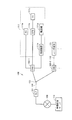
- FIG. 1 is a block diagram showing a schematic configuration of a PON system 100 according to an embodiment of the present invention. It is the figure which showed an example of the structure of the user terminal connected to ONU shown in FIG. It is a functional block diagram of OLT shown in FIG.
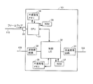
- FIG. 4 is a diagram schematically illustrating a hardware configuration example of the OLT illustrated in FIG. 3. It is a sequence diagram explaining processing of OLT when an event occurs in a normal state of OLT. It is the sequence diagram which showed the problem which may occur during the firmware update of a high-order process part.
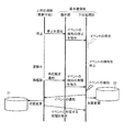
- 6 is a sequence diagram for explaining an OLT process according to the first embodiment.
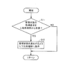
- FIG. It is a flowchart explaining the flow of a process of the matching part shown by FIG. FIG.
- FIG. 10 is a sequence diagram for explaining an OLT process according to the second embodiment. It is a flowchart explaining the flow of a process of the matching part shown by FIG.
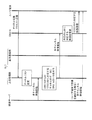
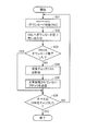
- FIG. 10 is a sequence diagram for explaining an OLT process according to the third embodiment. It is a flowchart explaining the flow of a process of the matching part shown by FIG.
- It is a sequence diagram for demonstrating typically the multichannel video delivery by the PON system which concerns on embodiment of this invention.
- It is a sequence diagram for demonstrating typically multi-channel video delivery in the case where the host processor of the OLT temporarily stops processing. It is a sequence diagram which shows the operation
- FIG. 1 is a block diagram showing a schematic configuration of a PON system 100 according to an embodiment of the present invention.
- a PON system 100 includes an OLT 101, ONUs 102-1, 102-2,..., 102-n, a PON line 104, and a splitter 105.
- the OLT 101 is installed in a telephone station, for example.
- Each of the ONUs 102-1 to 102-n is installed, for example, in the home of a network access service subscriber.
- a user terminal 111 is connected to each of the ONUs 102-1 to 102-n.
- the number of user terminals 111 connected to each ONU 102 is not particularly limited.
- a plurality of user terminals may be connected to one ONU.
- the type of the user terminal 111 is not particularly limited.
- the PON line 104 is composed of an optical fiber.
- the optical signal transmitted from the OLT 101 passes through the PON line 104 and is branched to the ONUs 102-1 to 102-n by the splitter 105.
- optical signals transmitted from the ONUs 102-1 to 102-n are converged by the splitter 105 and sent to the OLT 101 through the PON line 104.
- the splitter 105 passively branches or multiplexes the signal from the input signal without particularly requiring external power supply.
- the OLT 101 receives data via the upper network 109 and outputs the data to the PON line 104. According to the physical configuration of the PON, all of the ONUs 102-1 to 102-n can receive the data transmitted from the OLT 101. Therefore, the OLT 101 inserts an identifier LLID (Logical Link ID) that identifies an ONU that should receive the transmission frame into the preamble portion of the transmission frame. Each ONU collates the LLID included in the frame received from the OLT 101 with its own LLID notified from the OLT 101 in advance. If the LLID included in the frame matches its own LLID, the ONU receives the frame; otherwise, the ONU discards the frame.
- LLID Logical Link ID
- the optical signals transmitted from the respective ONUs merge at the splitter 105. For this reason, it is necessary to control so that the signals (upstream signals) from the ONUs do not collide after being joined by the splitter 105.
- the OLT 101 calculates the transmission start time and the transmission permission amount of data stored in the buffers in the ONUs 102-1 to 102-n based on the control frames (reports) transmitted from the ONUs 102-1 to 102-n. .
- the OLT 101 transmits the control frame (grant) in which the instruction signal is inserted to the ONUs 102-1 to 102-n via the PON line 104 and the splitter 105.
- the ONU 102-1 receives an uplink information frame from the user terminal 111 via the home network 110.
- the ONU 102-1 temporarily stores the uplink information frame in the buffer.
- the ONU 102-1 notifies the OLT 101 with a report of the length of data in its own buffer at the time designated by the grant.
- the ONU 102-1 receives the grant in which the instruction signal is inserted from the OLT 101, and based on the instruction signal, transmits the data in its own buffer together with the report to the OLT 101.
- FIG. 2 is a diagram showing an example of the configuration of a user terminal connected to the ONU shown in FIG.
- a user terminal 111 connected to the ONU 102-1 includes a personal computer (PC) 111a, a set top box (STB) 111b, a television receiver (TV) 111c, a telephone 111d, Connection device 111e.
- PC personal computer
- STB set top box
- TV television receiver
- a personal computer 111a, a set top box 111b, and a connection device 111e are connected to the ONU 102-1.
- a television receiver (TV) 111c is connected to the ONU 102-1 via a set top box 111b.
- the video distribution server 112 is connected to the upper network 109 (for example, the Internet).
- the video distribution server 112 provides a multi-channel distribution service to the user of the television receiver 111c via the PON system 100.
- the set top box 111b functions as a tuner for selecting a user's favorite channel from among multiple channels.
- the user operates the set top box 111b with a remote controller or the like (not shown) to select a channel corresponding to his / her desired program from multiple channels.
- a channel selection request is sent from the set top box 111b to the ONU 102-1.
- the ONU 102-1 transmits this channel selection request to the OLT 101 via the PON line 104.
- the OLT 101 receives a channel selection request from the ONU 102-1.
- the OLT 101 assigns an identifier LLID for identifying the ONU 102-1 to the video data of the channel corresponding to the channel selection request among the multi-channel video data sent from the video distribution server 112 via the upper network 109.
- the OLT 101 sends multi-channel video data to the PON line 104, the ONU 102-1 acquires only the video data to which the identifier LLID corresponding to itself is assigned. Thereby, the user can view a desired program.
- the telephone 111d is connected to the ONU 102-1 via the connection device 111e.
- the user can use a call service such as a VoIP service.
- the configuration of the user terminal 111 is not limited as shown in FIG. 2, and can be modified from the configuration shown in FIG. 2 according to the service desired by the user.
- a device connected to the ONU can be arbitrarily selected.
- other network devices eg, a hub (HUB), a router, etc.
- the television receiver 111c may have the function of the set top box 111b.
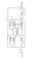
- FIG. 3 is a functional block diagram of the OLT shown in FIG.
- OLT 101 includes an upper processing unit 11, a basic communication unit 12, an optical interface (IF) unit 15, a communication processing unit 16, and an upper interface (IF) unit 18.
- IF optical interface
- IF upper interface
- the upper processing unit 11 is an upper layer processing unit that manages an upper layer of a layered communication protocol.
- the basic communication unit 12 includes a lower processing unit 13 that manages a lower layer of a layered communication protocol, and a matching unit 14.
- the layered communication protocol is a communication protocol according to the OSI (Open Systems Interconnection) reference model
- the “upper layer” refers to the third layer (network layer) and higher layers. It is.
- the “lower layer” is the first layer (physical layer) and the second layer (data link layer) of the OSI reference model.
- “Lower layer” (especially data link layer) protocols include MPCP (Multi-Point Control Protocol) and OAM (Operations, Administration and Maintenance) protocols.
- the upper processing unit 11 and the basic communication unit 12 communicate with each other.
- a protocol used for communication between the host processing unit 11 and the basic communication unit 12 is, for example, TCP / IP.
- the host processing unit 11 has a storage unit 21 that holds information regarding the state of the PON system.
- the host processing unit 11 updates the state stored in the storage unit 21 when an event is notified from the lower processing unit 13.
- the basic communication unit 12 includes a storage unit 22 that holds information regarding the state of the PON system.
- the storage unit 22 is configured as a part of the lower processing unit 13. However, the storage unit 22 may be provided separately from the lower processing unit 13.
- the lower processing unit 13 detects the event and notifies the upper processing unit 11 of the event. Further, the lower processing unit 13 updates the state according to the detected event.
- the lower processing unit 13 When the lower processing unit 13 receives an instruction from the upper processing unit 11 for an event notified to the upper processing unit 11, the lower processing unit 13 executes processing according to the instruction.
- the lower processing unit 13 detects that an ONU is additionally connected in accordance with MPCP. That is, the lower processing unit 13 detects an event that an ONU is additionally connected. In this case, the lower processing unit 13 stores information that a new ONU is connected in the storage unit 22 and notifies the higher processing unit 11 of the event.
- the upper processing unit 11 stores information that a new ONU is connected in the storage unit 21 when an event is notified from the lower processing unit 13. Next, the upper processing unit 11 assigns an LLID for the ONU and sends an instruction to notify the new ONU of the LLID to the lower processing unit 13. As a result, the lower processing unit 13 notifies the LLID to the new ONU.
- the upper processing unit 11 determines the transmission band and transmission timing of the uplink signal transmitted from the new ONU to the OLT, and instructs the new ONU to notify the transmission band and transmission timing.
- the lower processing unit 13 notifies the new ONU of the transmission band and the transmission timing according to the instruction from the upper processing unit 11.
- the lower processing unit 13 monitors the ONU and PON lines according to the OAM protocol. For example, when detecting the abnormality of the PON line as an event, the lower processing unit 13 notifies the higher processing unit 11 of the event. In this case, for example, the host processing unit 11 notifies the event (abnormality of the PON line) to the terminal device of the operator who maintains and operates the PON system through the host network 109.
- each of the upper processing unit 11 and the lower processing unit 13 has a storage unit for holding the state of the network.
- the storage units hold the management state in the form of a database, for example.
- each of the upper processing unit 11 and the lower processing unit 13 can manage the state of the network. Since each of the upper processing unit 11 and the lower processing unit 13 has a storage unit, the processing can be made independent for each module, so that the processing for communication control can be hierarchized into an upper layer and a lower layer.
- the optical interface unit 15 is connected to the PON line 104 (optical fiber).
- the optical interface unit 15 converts the optical signal (upstream signal) received from the PON line 104 into an electrical signal, while converting the input electrical signal (downstream signal) into an optical signal and sends the optical signal to the PON line 104. Send it out.
- the communication processing unit 16 determines that the uplink signal transmitted from the ONU to the OLT 101 is a data signal, the communication processing unit 16 executes various processes for transmitting the data signal from the OLT 101 to the upper network 109. Further, the communication processing unit 16 executes various processes for transmitting a downstream signal (data signal) transmitted from the upper network 109 to the OLT 101 to the ONU through the PON line 104.
- control frame when a control frame is transmitted from the ONU to the OLT 101, the communication processing unit 16 transmits the control frame to the basic communication unit 12 (lower processing unit 13).
- the communication processing unit 16 receives the control frame to be sent to the ONU from the basic communication unit 12 (lower processing unit 13), and transmits the control frame to the PON line.
- a process for sending to 104 is executed.
- This “control frame” includes an MPCP frame and an OAM frame.
- Firmware is installed in the upper processing unit 11.
- the firmware of the upper processing unit 11 may be updated to new firmware for reasons such as addition of new functions and modification of problems.
- the processing of the upper processing unit 11 is stopped.
- the lower processing unit 13 continues to operate. Thereby, it is possible to prevent the data communication between the OLT and the ONU from being stopped.
- the lower processing unit 13 can update the state stored in the storage unit 22, while the upper processing unit 11 stores in the storage unit 21.
- the held management state cannot be updated. For this reason, when the upper processing unit 11 is restarted, the state managed by the upper processing unit 11 (that is, information stored in the storage unit 21) and the state managed by the lower processing unit 13 (that is, stored in the storage unit 22). Information) may not match.
- the matching unit 14 manages the management stored in the storage unit 21 of the upper processing unit 11 after the stop period of the upper processing unit 11.
- the state and the management state stored in the storage unit 22 of the lower processing unit 13 are matched. Specific processing of the matching unit 14 will be described in detail later.
- FIG. 4 is a diagram schematically showing a hardware configuration example of the OLT shown in FIG.
- an OLT 101 includes a CPU 31, a control LSI (Large Scale Integrated circuit) 32, an optical transmission / reception circuit 33, a nonvolatile memory 34, a RAM 35, a nonvolatile memory 36, a RAM 37, and a transmission / reception circuit. 38.
- LSI Large Scale Integrated circuit
- the CPU 31 has firmware installed. When the CPU executes a process according to the firmware, the CPU 31 realizes the upper processing unit 11 shown in FIG.
- Updating the firmware of the CPU 31 can flexibly cope with enhancement of the functionality of the OLT 101, expansion of the functions of the OLT 101, and the like.
- the new firmware is sent to the management interface 39 through the network 115 by a protocol such as FTP.
- FTP a protocol such as FTP.
- the CPU 101 is restarted to update the firmware installed in the CPU 101 to new firmware. For example, when the CPU 101 receives a command sent from a computer connected to the network 115, the CPU 101 restarts and reads the firmware stored in the nonvolatile memory 34. This updates the firmware.
- the RAM 35 temporarily stores data when the CPU 31 performs processing.
- the storage unit 21 can be realized by the RAM 35.
- the CPU 31 may store the information stored in the storage unit 21 in the non-volatile memory 34 or other non-volatile memory at an appropriate timing so that the information stored in the storage unit 21 is not lost.
- the control LSI 32 implements, for example, the basic communication unit 12 and the communication processing unit 16.
- the RAM 37 temporarily stores data when the control LSI 32 performs processing.
- the storage unit 22 can be realized by the RAM 37.
- information stored in the storage unit 22 may be stored in the nonvolatile memory 36.
- the optical transmission / reception circuit 33 implements the optical interface unit 15.
- the transmission / reception circuit 38 implements the upper interface unit 18.
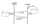
- FIG. 5 is a sequence diagram for explaining OLT processing when an event occurs in a normal state of the OLT.
- the “normal state” corresponds to a case where the host processing unit 11 has not temporarily stopped its operation (in a specific example, there is no firmware update).
- basic communication unit 12 detects the event.
- the basic communication unit 12 notifies the host processing unit 11 of the event, and stores information related to the state of the PON system 100 to be managed by the basic communication unit 12 in the storage unit 22.
- the database configured by the storage unit 22 is updated, and as a result, the state managed by the basic communication unit 12 (the state of the PON system 100) is changed.
- the upper processing unit 11 when the event is notified from the basic communication unit 12, the upper processing unit 11 reflects the notification content in the database configured by the storage unit 21. As a result, the database of the host processor 11 is updated, and as a result, the state managed by the host processor 11 (the state of the PON system 100) is updated. Furthermore, the upper processing unit 11 instructs the basic communication unit 12 to perform processing corresponding to the event notified to the upper processing unit 11 as necessary.
- FIG. 6 is a sequence diagram showing problems that may occur during the firmware update of the host processing unit.
- the basic communication unit 12 does not have the function of the matching unit 14, problems described below may occur.
- the basic communication unit 12 detects an event.
- the basic communication unit 12 notifies the host processing unit 11 of the event.
- the processing of the upper processing unit 11 is stopped.
- the notification from the basic communication unit 12 is not accepted by the host processing unit 11.
- the information held in the storage unit 21 is not updated. Therefore, after the upper processing unit 11 is restarted, a mismatch occurs between the state managed by the basic communication unit 12 and the state managed by the upper processing unit 11. Furthermore, the processing instruction corresponding to the event is not sent to the basic communication unit 12.
- the matching unit 14 sets the stop period of the upper processing unit 11 when an event occurs while the upper processing unit 11 is temporarily stopped. Later, the management state stored in the storage unit 21 of the upper processing unit 11 and the management state stored in the storage unit 22 of the lower processing unit 13 are matched. Thereby, after the upper processing unit 11 is restarted, the same state as the state in which the processing of the upper layer and the notification of the event are executed is created. Therefore, the upper processing unit 11 and the basic communication unit 12 smoothly Processing can be executed. For example, as in the normal state, the host processing unit 11 can send an instruction for an event detected by the basic communication unit 12 to the basic communication unit 12.
- the processing by the matching unit 14 will be described in detail for each embodiment.
- FIG. 7 is a sequence diagram for explaining the OLT processing according to the first embodiment.
- the upper processing unit 11 notifies the matching unit 14 of the stop of the upper processing unit 11.
- the matching unit 14 detects that the upper processing unit 11 is stopped by the notification from the upper processing unit 11. Thereby, the matching unit 14 instructs the lower processing unit 13 to accumulate events to be notified to the higher processing unit 11.
- the lower processing unit 13 updates the database on the basic communication unit 12 side (database configured by the storage unit 22) and accumulates events to be notified to the upper processing unit 11 by detecting the event.
- the firmware of the upper processing unit 11 is updated, and the upper processing unit 11 is restarted.
- the upper processing unit 11 notifies the matching unit 14 that the upper processing unit 11 has been restarted.
- the matching unit 14 detects that the upper processing unit 11 has been restarted by a notification from the upper processing unit 11. Thereby, the matching unit 14 instructs the lower processing unit 13 to cancel the accumulation of the event, and also instructs the higher processing unit 11 to notify the accumulated event.
- the lower processing unit 13 notifies the upper processing unit 11 of the events accumulated during the stop period of the upper processing unit 11 (that is, the firmware update period). Thereafter, similar to the processing shown in FIG. 5, the upper processing unit 11 updates the database on the upper processing unit 11 side (database configured by the storage unit 21) according to the event notified from the lower processing unit 13. . Furthermore, the upper processing unit 11 instructs the lower processing unit 13 to perform processing corresponding to the event notified from the lower processing unit 13 as necessary.
- FIG. 8 is a flowchart for explaining the flow of processing of the matching unit shown in FIG. The processing shown in this flowchart is executed at a constant cycle, for example.
- step S ⁇ b> matching unit 14 determines whether or not a stop notification has been received from host processing unit 11. If the matching unit 14 has not received a stop notification from the upper processing unit 11 (NO in step S1), the processing described below is skipped. If matching unit 14 receives a stop notification from host processing unit 11 (YES in step S1), the process proceeds to step S2.
- step S2 the matching unit 14 instructs the lower processing unit 13 to accumulate events.
- the lower processing unit 13 accumulates events to be notified to the higher processing unit 11.
- the lower processing unit 13 updates its own database every time an event occurs.
- step S3 the matching unit 14 determines whether a restart notification has been received from the host processing unit 11. If matching unit 14 has not received a stop notification from host processing unit 11 (NO in step S3), the process in step S3 is repeated. When matching unit 14 receives a restart notification from host processing unit 11 (YES in step S3), the process proceeds to step S4.
- step S4 the matching unit 14 instructs the lower processing unit 13 to cancel the accumulation of the event and notify the accumulated event.
- the basic communication unit 12 cancels the accumulation of the event and notifies the upper processing unit 11 of the accumulated event.
- the host processing unit 11 updates its own database according to the notified event.
- the matching unit 14 causes the lower processing unit 13 to accumulate events that occur during the stop period (firmware update period) of the upper processing unit 11.
- the matching unit 14 notifies the events accumulated in the upper processing unit 11 from the lower processing unit 13 after the stop period of the upper processing unit 11 elapses. Therefore, the state managed by the upper processing unit 11 (information stored in the storage unit 21) after the restart of the upper processing unit 11 and the state managed by the lower processing unit 13 (information stored in the storage unit 22) are matched. Can be made. Thereby, inconsistency of the management state between the upper processing unit 11 and the lower processing unit 13 can be prevented in advance.
- FIG. 9 is a sequence diagram for explaining the OLT processing according to the second embodiment.
- the upper processing unit 11 prior to stopping the process, the upper processing unit 11 notifies the matching unit 14 of the stop of the upper processing unit 11.
- the matching unit 14 detects that the upper processing unit 11 is stopped by the notification from the upper processing unit 11. Thereby, the matching unit 14 instructs the lower processing unit 13 to stop detecting the event.
- the lower processing unit 13 stops detecting the event.
- the firmware of the upper processing unit 11 is updated, and the upper processing unit 11 is restarted.
- the upper processing unit 11 notifies the matching unit 14 that the upper processing unit 11 has been restarted.
- the matching unit 14 detects that the upper processing unit 11 has been restarted by a notification from the upper processing unit 11. Thereby, the matching unit 14 instructs the lower processing unit 13 to resume the detection of the event.
- the lower processing unit 13 restarts the detection of the event in response to an instruction from the matching unit 14.
- FIG. 10 is a flowchart for explaining the flow of processing of the matching unit shown in FIG.
- the processing shown in this flowchart is executed at a constant cycle, for example.
- the processes of steps S2A and S4A are executed instead of the processes of steps S2 and S4.
- the process proceeds to step S2A.
- step S2A the matching unit 14 instructs the lower processing unit 13 to stop detecting the event.
- the lower processing unit 13 stops detecting the event.
- step S3 the matching unit 14 determines whether a restart notification has been received from the host processing unit 11.
- step S3 the process proceeds to step S4A.
- step S4A the matching unit 14 instructs the lower processing unit 13 to resume the detection of the event.
- the lower processing unit 13 resumes the detection of the event.
- detection of an event by the lower processing unit 13 is also stopped while the firmware of the upper processing unit 11 is updated.
- the lower processing unit 13 detects the event after the upper processing unit 11 is restarted.
- the lower processing unit 13 notifies the detected event to the higher processing unit 11 and updates its own database.
- the upper processing unit 11 updates its own database in response to the notification from the lower processing unit 13. Furthermore, the upper processing unit 11 sends an instruction for processing corresponding to the event notified from the lower processing unit 13 to the lower processing unit 13 as necessary.
- the second embodiment similarly to the first embodiment, even if the upper processing unit 11 is temporarily stopped, the state managed by the higher processing unit 11 and the lower processing unit 13 manage after the restart.
- the state can be matched. That is, according to the second embodiment, as in the first embodiment, it is possible to prevent inconsistency in the management state between the upper processing unit 11 and the lower processing unit 13.
- a first example of an event detected by the lower processing unit 13 is an MPCP link down event.
- the lower processing unit 13 stops detecting the MPCP link down event by stopping the MPCP timeout monitoring.
- MPCP timeout monitoring is performed by the following method.
- the OLT 101 periodically transmits an MPCP gate frame to the ONU 102.
- the lower processing unit 13 monitors whether an MPCP frame (report) serving as a response to the gate frame arrives from the ONU 102 within a predetermined period.
- the lower processing unit 13 detects an MPCP link down event. In the case of MPCP, this predetermined period is defined as 1 second.
- a second example of an event detected by the lower processing unit 13 is an OAM link down event.
- the lower processing unit 13 stops detecting the OAM link down event by stopping the OAM timeout monitoring.
- OAM timeout monitoring is performed in the same manner as MPCP timeout monitoring.
- the timeout period is defined as 5 seconds.
- a third example of an event detected by the lower processing unit 13 is an MPCP link up event.
- the lower processing unit 13 stops detecting the MPCP link up event by stopping transmission of the discovery frame.
- the OLT 101 periodically broadcasts a Discovery frame to all ONUs in order to detect an ONU newly connected to the PON line 104. An ONU newly connected to the PON line 104 is not registered in the OLT 101. For this reason, a Register Request frame requesting to register itself is sent from the ONU to the OLT 101. The OLT 101 assigns an LLID to this ONU and establishes a communication link with the ONU. The information of the newly registered ONU is registered in both the database on the upper processing unit 11 side and the database on the lower processing unit 13 side.
- FIG. 11 is a sequence diagram for explaining the OLT processing according to the third embodiment.
- the upper processing unit 11 stops the process for updating the firmware.
- the lower processing unit 13 changes the management state stored in its own database and notifies the upper processing unit 11 of the event.
- the upper processing unit 11 does not accept the notification from the lower processing unit 13 because the processing is stopped.
- the upper processing unit 11 When the firmware update is completed, the upper processing unit 11 is restarted. Next, the host processing unit 11 transmits a management state acquisition request to the basic communication unit 12.
- the matching unit 14 receives the management status acquisition request from the upper processing unit 11, the matching unit 14 instructs the lower processing unit 13 to notify the management status.
- the lower processing unit 13 In response to an instruction from the matching unit 14, the lower processing unit 13 notifies the upper processing unit 11 of the management state (information stored in the storage unit 22) stored in its own database.
- the upper processing unit 11 collates the management state stored in its own database (information stored in the storage unit 22) with the management state notified from the lower processing unit 13. If there is a difference between the management states of the two, the upper processing unit 11 reflects the difference in its own database. As a result, the state managed by the upper processing unit 11 matches the state managed by the lower processing unit 13.
- the upper processing unit 11 instructs the lower processing unit 13 to perform processing corresponding to the event as necessary.
- FIG. 12 is a flowchart for explaining the flow of processing of the matching unit shown in FIG.
- the processing shown in this flowchart is executed at a constant cycle, for example.
- step S ⁇ b> 11 it is determined whether matching unit 14 has received a management status acquisition request from host processing unit 11. If the matching unit 14 has not received a management state acquisition request from the higher-level processing unit 11 (NO in step S11), the processing in step S12 is skipped.
- step S12 the matching unit 14 instructs the lower processing unit 13 to notify the upper processing unit 11 of the management state.
- the lower processing unit 13 notifies the higher processing unit 11 of the management state stored in the storage unit 22.
- the host processing unit 11 transmits a management state acquisition request to the basic communication unit 12 after restarting.
- the matching unit 14 causes the lower processing unit 13 to notify the upper processing unit 11 of the management state. Therefore, according to the third embodiment, the state (information stored in the storage unit 21) managed by the upper processing unit 11 and the basic communication unit 12 after the upper processing unit 11 is restarted, as in the first and second embodiments. Can be matched with the state managed by (information stored in the storage unit 22).
- the basic communication unit 12 changes its management state every time an event occurs. For this reason, the management state of the upper processing unit 11 and the management state of the basic communication unit 12 may be different from each other during the firmware update of the upper processing unit 11. According to the third embodiment, such a discrepancy in the management state can be eliminated.
- the station side apparatus of the present invention is suitably applied to a communication network in which communication between the ONU and the OLT needs to be constantly maintained, such as a PON system.
- a communication network in which communication between the ONU and the OLT needs to be constantly maintained, such as a PON system.
- FIG. 13 is a sequence diagram for schematically explaining multi-channel video distribution processing by the PON system according to the embodiment of the present invention.
- the user switches the viewing channel of the user terminal (for example, STB 111b shown in FIG. 2)
- ONU-A optical signal
- the OLT 101 receives the channel switching request.
- the channel switching request is processed by the host processing unit 11.
- the host processing unit 11 changes a channel list in which ONUs and viewing channels are associated with each other in response to a channel switching request.
- multi-channel video data is distributed from the video server.
- the OLT 101 assigns the ONU-A LLID to the video data of the channel corresponding to the request from the ONU-A according to the channel list. Then, the OLT 101 delivers multi-channel video.
- the distribution format of the video data from the OLT 101 may be unicast or multicast.
- the ONU-A receives the video (data) to which the LLID that matches its own LLID is given from the multi-channel video sent from the OLT 101.
- the ONU-A transmits the received video to the user terminal. Thereby, the user terminal can receive the video corresponding to the channel switching request.
- the multi-channel video data sent from the video server is transmitted from the ONU through the home side network, as indicated by the broken arrow in FIG. Sent to user terminal.
- the transmission capacity of the home-side network is smaller (for example, 100 Mbps) than the transmission capacity of the PON line (for example, 10 Gbps). Therefore, when a large amount of data is transmitted to the home side network, an influence on the home side network (for example, a delay in data transmission) may occur. Since the OLT 101 (specifically, the upper processing unit) manages the ONU and the channel in association with each other, only the video data of the channel desired by the user is distributed to the home side network, so that the above problem can be prevented.
- the basic communication unit 12 continues to operate even when the host processing unit 11 temporarily stops. As a result, the operations of the upper IF unit, the communication processing unit 16 and the optical IF unit 15 are also continued. For this reason, it is possible to reduce the influence of the user on viewing the video.
- the video displayed on the user terminal also needs to be switched to a new channel video within a time appropriate for the user.
- the upper processing unit 11 is stopped due to firmware update.
- the basic communication unit 12 receives a request transmitted from the ONU when the upper processing unit 11 is temporarily stopped.
- the basic communication unit 12 notifies the upper processing unit 11 of the request.
- the same state as the state in which the host processing unit 11 has received the request can be created.
- the host processing unit 11 executes the same processing as the processing shown in FIG. Therefore, the ONU that has transmitted the channel switching request can receive the video data of the new channel. Furthermore, by shortening the stop time (firmware update time) of the host processing unit 11, it is possible to shorten the time lag from when the user performs the channel switching operation until the channel is actually switched at the terminal (TV). It is.
- the OLT updates the firmware of a plurality of ONUs all at once.
- the OLT sends one data to the PON line, all the ONUs can receive the data. This function is realized by the upper processing unit of the OLT.
- FIG. 15 is a sequence diagram showing an operation procedure of data download in the PON system according to the embodiment of the present invention. Here, a case where the common management data is divided into N blocks will be described.
- the OLT transmits a control frame for notifying “download start” to each ONU (SQ1).
- each ONU receives a control frame indicating “download start” from the OLT, and transitions to a download state. Then, each ONU transmits a control frame indicating that it has transitioned to the download state to the OLT (SQ2).
- the OLT receives a control frame indicating the transition from each ONU to the download state, puts block 1 out of N blocks in the control frame, and puts a broadcast LLID in the control frame. (SQ3).
- each ONU receives the control frame including the block 1 from the OLT, stores the block 1, and transmits Ack (Acknowledge) 1 indicating that the block 1 has been received normally to the OLT. (SQ4).
- the OLT receives a control frame including Ack1 from each ONU, puts block 2 out of N blocks in the control frame, and puts a broadcast LLID in the control frame and broadcasts it to each ONU (SQ5). ).
- each ONU receives a control frame including the block 2 from the OLT, saves the block 2, puts Ack2 indicating that the block 2 has been normally received, and transmits it to the OLT (SQ6).
- SQ6 OLT
- each ONU repeat transmission and reception of block 3 to block N-1. Then, the OLT broadcasts the block N (SQ7), and each ONU transmits an AckN in the control frame to the OLT (SQ8).
- each ONU updates management data when all of the blocks 1 to N are successfully received.
- the OLT receives a control frame including AckN from each ONU, and transmits a control frame indicating an inquiry as to whether or not the download of block 1 to block N has been normally completed to each ONU (SQ9).
- each ONU receives a control frame indicating an inquiry from the OLT, and transmits a control frame indicating whether or not the downloading of the blocks 1 to N is normally completed to the OLT (SQ10).
- the incomplete ONU receives the control frame including the block i from the OLT, saves the block i, puts Acki indicating that the block i has been normally received, and transmits it to the OLT (SQ12). ).
- the incomplete ONU updates the management data.
- the OLT receives a control frame including Acchi from the incomplete ONU and transmits a control frame indicating an inquiry as to whether or not the download of the blocks 1 to N has been normally completed to the incomplete ONU (SQ13 ).
- each ONU including the incomplete ONU receives a control frame indicating an inquiry from the OLT, and transmits a control frame indicating a state in which the downloading of the blocks 1 to N is normally completed to the OLT (SQ14).
- the OLT When the OLT receives a control frame indicating a state in which the download of the block 1 to the block N is normally completed from each ONU, the OLT ends the download process.
- FIG. 16 is a sequence diagram showing a procedure of a preparation operation before the start of broadcasting in the PON system according to the embodiment of the present invention.
- FIG. 16 corresponds to the operations of sequences SQ1 and SQ2 shown in FIG.
- ONU-A and ONU-B the OLT and two ONUs
- Each ONU communicating with one OLT, that is, connected to one OLT may have a mix of manufacturer, software version, and hardware version, and not all ONUs download the same management data Not necessarily the target.
- the OLT grasps the ONU that should download the common management data, that is, the ONU to be downloaded. First, the OLT generates a control message that notifies “download start”, puts it in the control frame, and puts the broadcast LLID in the control frame and broadcasts it to the ONU-A and ONU-B (SQ21A and SQ21B).
- This control message includes the type of common management data in addition to the “download start” notification.
- the types of common management data include, for example, the manufacturer name, software version, and hardware version of the ONU to be downloaded.
- the type of common management data includes the type of device to be downloaded, that is, whether the common management data is a software program such as a CPU, FPGA data, or operation instruction information.
- the types of common management data include the version of the common management data itself, the size of the common management data, the size of the divided block of the common management data, and the date of the common management data.
- ONU-A and ONU-B confirm the control message included in the control frame received from the OLT, its own setting, version, and the like. That is, the ONU compares the type of the common management data indicated by the control message with its own setting and version, etc., and determines whether or not it satisfies the download conditions for the common management data (SQ22 and SQ24). .
- the ONU-A determines that the download condition is satisfied, that is, the common management data should be downloaded (SQ23), the ONU-A transitions to the download state and transmits a control frame indicating the transition to the download state to the OLT. (SQ26).
- the ONU-B determines that the download condition is not satisfied (SQ25)
- the ONU-B does not transit to the download state and transmits a control frame indicating that the download state has not been transited to the OLT (SQ27).
- the OLT receives the control frame indicating that the ONU-A has transitioned to the download state and the control frame indicating that the ONU-B has not transitioned to the download state, and identifies the ONU-A that has entered the download state.
- a number such as a unicast LLID is stored, that is, ONU-A is added to the download target. This stored content is used in a download completion confirmation process described later (SQ28).
- FIG. 17 is a flowchart defining an operation procedure when the OLT performs broadcasting in the PON system according to the embodiment of the present invention.
- FIG. 17 corresponds to the operations of sequences SQ3, SQ5, and SQ7 shown in FIG.
- This flowchart shows a scheme in which the OLT transmits the next block in response to a response from the ONU to the transmission of the common management data block.
- the OLT calculates the total number of transmission blocks, that is, calculates the number of divided blocks of common management data (S22).
- the OLT broadcasts the i-th block to each ONU (S23).
- the OLT receives a response (Ack) from each ONU within a predetermined time after broadcasting the block (YES in S24)
- the OLT broadcasts the i-th block to each ONU, that is, broadcasts the next block (S23).
- the OLT does not receive a response from each ONU within a predetermined time from broadcasting the block (NO in S24), it retransmits the same block (S23).
- the OLT ends the broadcast process.
- FIG. 18 is a flowchart defining an operation procedure when the OLT in the PON system according to the embodiment of the present invention performs a download completion confirmation.
- FIG. 18 corresponds to the operations of sequences SQ9 to SQ14 shown in FIG.
- the OLT selects one of the ONUs to be downloaded recognized by the operation shown in FIG. 16, and assigns the identification number of the selected ONU, for example, a unicast LLID to variable onu. (S31).
- the OLT inquires the selected ONU about the completion of download.
- the OLT puts the LLID of the variable onu in a control frame indicating an inquiry as to whether or not the download of the common management data has been completed normally and transmits it to the PON line (S32).
- the OLT receives a response indicating that the download has been completed from the selected ONU (YES in S33), there is an ONU for which download completion has not been confirmed among the ONUs to be downloaded. (NO in S36), an unconfirmed ONU is selected, and the identification number of the selected ONU, for example, a unicast LLID is substituted into the variable onu (S31).
- the OLT receives a response indicating that the download has not been completed from the selected ONU (NO in S33), based on the “reception checklist” acquired from the ONU, It is confirmed which block is not normally received, and an abnormally received block is transmitted to the OLT. That is, the OLT puts an abnormally received block in the control frame, puts the unicast LLID of the ONU in the control frame and transmits it to the PON line (S35), and performs the process of step S36.
- the OLT checks whether or not each ONU has completed the download. If not, only the blocks that have not been normally received are individually retransmitted to the ONU. Send.
- the ONU download can be completed even when a block is lost in the transmission path from the OLT to the ONU.
- the basic communication unit receives a message to be received by the upper processing unit instead during a period in which the upper processing unit cannot execute the processing. Then, after the upper processing unit is restarted, the basic communication unit transmits the message to the upper processing unit.
- the upper processing unit 11 notifies the basic communication unit 12 when the process is stopped and restarted.
- the basic communication unit 12 (matching unit 14) can detect that the host processing unit 11 has been stopped and restarted.
- the basic communication unit 12 confirms that the update of the firmware of the upper processing unit 11 is started by the communication with the upper processing unit 11 being interrupted (for example, the session is closed when the communication is performed by TCP / IP). It may be detected. Therefore, in this case, the basic communication unit 12 may detect the restart of the upper processing unit 11 by restarting communication with the upper processing unit 11.
- the matching unit 14 is configured as a part of the basic communication unit 12. However, the matching unit 14 may be provided separately from the basic communication unit 12.
- firmware update and OLT restart are exemplified as an example of the case where the station side apparatus temporarily stops processing.
- the present invention is not limited to the case of firmware update, and can be applied to an OLT including an upper processing unit having a possibility of temporarily stopping processing, and a PON system including the OLT.
Landscapes
- Engineering & Computer Science (AREA)
- Computer Networks & Wireless Communication (AREA)
- Signal Processing (AREA)
- Multimedia (AREA)
- Computing Systems (AREA)
- Physics & Mathematics (AREA)
- Electromagnetism (AREA)
- Small-Scale Networks (AREA)
Abstract
Description
図7は、実施の形態1に係るOLTの処理を説明するためのシーケンス図である。図3および図7を参照して、処理を停止するに先立ち、上位処理部11は整合部14に対して上位処理部11の停止を通知する。整合部14は、上位処理部11からの通知により、上位処理部11が停止することを検知する。これにより整合部14は、下位処理部13に対して、上位処理部11に通知すべきイベントを蓄積するよう指示する。下位処理部13は、イベントの検知によって、基本通信部12側のデータベース(記憶部22により構成されたデータベース)を更新するとともに上位処理部11に通知すべきイベントを蓄積する。
図9は、実施の形態2に係るOLTの処理を説明するためのシーケンス図である。図3および図9を参照して、処理を停止するに先立ち、上位処理部11は整合部14に上位処理部11の停止を通知する。整合部14は、上位処理部11からの通知により、上位処理部11が停止することを検知する。これにより、整合部14は、下位処理部13に対して、イベントの検知を停止するよう指示する。下位処理部13は、整合部14からの指示により、イベントの検知を停止する。
下位処理部13によって検知されるイベントの第1の例は、MPCPリンクダウンイベントである。下位処理部13は、MPCPタイムアウト監視を停止することによって、MPCPリンクダウンイベントの検知を停止する。
図11は、実施の形態3に係るOLTの処理を説明するためのシーケンス図である。図3および図11を参照して、上位処理部11は、ファームウェアの更新のために処理を停止する。上位処理部11のファームウェアの更新中にイベントが発生した場合、下位処理部13は、自身のデータベースに記憶された管理状態を変更するとともに、上位処理部11にイベントを通知する。ただし、上位処理部11は、その処理を停止しているために下位処理部13からの通知を受付けない。
(第1の例)
第1の例は、多チャンネル映像データの配信である。図13は、本発明の実施の形態に係るPONシステムによる多チャンネル映像配信の処理を模式的に説明するためのシーケンス図である。図13を参照して、ユーザがユーザ端末(たとえば図2に示すSTB111b)の視聴チャネルを切換えた場合、ユーザ端末からチャネル切換リクエストが送信される。このチャネル切換リクエストは、当該ユーザのONU(ONU-Aとする)によって光信号に変換されて、OLT101に送信される。
第2の例は、OLTが複数のONUのファームウェアを一斉に更新する例である。一般のアクセス網であれば、複数のONUに個別にデータを送信する必要がある。これに対して、PONシステムでは、OLTが1つのデータをPON回線に送出すれば、すべてのONUがそのデータを受信できる。この機能はOLTの上位処理部によって実現される。
次に、OLTは、トータル送信ブロック数を算出する、すなわち共通管理データの分割ブロック数を算出する(S22)。
次に、OLTは、ブロックをブロードキャストした時から所定時間内に各ONUからの応答(Ack)を受信した場合には(S24でYES)、変数i=i+1に設定する(S25)。
ブロックを当該OLTへ送信する。すなわち、OLTは、未正常受信のブロックを制御フレームに入れ、当該ONUのユニキャストLLIDを制御フレームに入れてPON回線へ送信し(S35)、ステップS36の処理を行なう。
Claims (10)
- 宅側装置とともにネットワークシステムを構成する局側装置であって、
階層化された通信プロトコルの上位レイヤを司り、前記ネットワークシステムの状態を記憶するための第1の記憶部(21)を有し、前記ネットワークシステムで発生したイベントが通知されることにより、前記第1の記憶部(21)に記憶された前記ネットワークシステムの状態を更新する上位レイヤ処理部(11)と、
前記階層化された通信プロトコルの下位レイヤを司り、前記ネットワークシステムの状態を記憶するための第2の記憶部(22)を有し、イベントの発生を検知して、前記イベントを前記上位レイヤ処理部(11)に通知するとともに前記第2の記憶部(22)に記憶された前記ネットワークシステムの状態を前記イベントに基づいて更新する下位レイヤ処理部(13)とを備え、
前記上位レイヤ処理部(11)は一時的に停止しうる一方で、前記上位レイヤ処理部(11)が一時的に停止した場合であっても、前記下位レイヤ処理部(13)は、その動作を維持できるように構成され、
前記局側装置は、
前記上位レイヤ処理部(11)の停止期間の間にイベントが発生した場合には、前記上位レイヤ処理部(11)の前記停止期間の後に、前記第1の記憶部(21)に記憶された状態と前記第2の記憶部(22)に記憶された状態とを整合させる整合部(14)をさらに備える、局側装置。 - 前記整合部(14)は、前記上位レイヤ処理部(11)が一時的に停止する場合には、前記上位レイヤ処理部(11)の前記停止期間の間に発生したイベントを蓄積するための指示を前記下位レイヤ処理部(13)に送り、前記上位レイヤ処理部(11)の前記停止期間の後には、前記蓄積されたイベントを前記上位レイヤ処理部(11)に通知するための指示を前記下位レイヤ処理部(13)に送る、請求項1に記載の局側装置。
- 前記整合部(14)は、前記上位レイヤ処理部(11)が一時的に停止する場合には、前記イベントの検知を停止するための指示を前記下位レイヤ処理部(13)に送り、前記上位レイヤ処理部(11)の前記停止期間の後には、前記イベントの検知を再開するための指示を前記下位レイヤ処理部(13)に送る、請求項1に記載の局側装置。
- 前記整合部(14)は、前記上位レイヤ処理部(11)の前記停止期間の後に、前記第2の記憶部(22)に記憶された前記ネットワークシステムの状態を前記上位レイヤ処理部(11)に通知するための指示を前記下位レイヤ処理部(13)に送る、請求項1に記載の局側装置。
- 前記ネットワークシステムは、受動型光ネットワークシステムであり、
前記下位レイヤのプロトコルは、MPCPまたはOAMであり、
前記上位レイヤのプロトコルは、前記MPCPおよび前記OAMよりも上位レイヤに属するプロトコルである、請求項1に記載の局側装置。 - 前記上位レイヤ処理部(11)は、前記ネットワークシステムに他の宅側装置が追加接続されたというイベントが前記下位レイヤ処理部(13)から通知された場合に、前記局側装置と前記他の宅側装置との間の通信リンクを確立するように前記下位レイヤ処理部(13)に指示する、請求項5に記載の局側装置。
- 前記局側装置は、上位ネットワークを経由して受信した多チャネルの映像データを、宅側装置に配信し、
前記上位レイヤ処理部(11)は、前記多チャネルの映像データの中から1つのチャネルの映像データを選択するためのリクエストを前記宅側装置から受信して、前記1つのチャネルの映像データの配信先に前記宅側装置を含める処理を実行する、請求項1に記載の局側装置。 - 前記停止期間は、前記上位レイヤ処理部(11)に実装されたファームウェアを新しいファームウェアに更新するための期間を含む、請求項1に記載の局側装置。
- 局側装置においてネットワークシステムを管理する制御方法であって、
階層化された通信プロトコルの上位レイヤに関する上位レイヤ処理を実行するステップと、
前記階層化された通信プロトコルの下位レイヤに関する下位レイヤ処理を実行するステップと、
前記ネットワークシステムにおいて発生したイベントを、前記下位レイヤ処理を実行する処理部から、前記上位レイヤ処理を実行する処理部へと通知するステップとを備え、
前記上位レイヤ処理が実行できる期間においては、前記下位レイヤ処理および前記上位レイヤ処理ならびに前記イベントの通知が実行され、
前記上位レイヤ処理が実行できない期間においては、前記下位レイヤ処理を実行しておいて、前記上位レイヤ処理が実行できる期間の開始後に、当該期間において前記上位レイヤ処理と前記イベントの通知とが実行された状態と同じ状態を作るステップをさらに備える、制御方法。 - 局側装置と、受動的光ネットワークを介して前記局側装置と接続された複数の宅側装置とによって構成されるPONシステムの制御方法であって、
前記局側装置から前記受動的光ネットワークに配信される多チャネルの映像データの中から1つのチャネルの映像データを選択するためのリクエストを、前記複数の宅側装置のうちの少なくとも1つの宅側装置が前記局側装置に送信するステップと、
前記局側装置の上位レイヤ処理部(11)が、前記リクエストを受信するステップと、
上位ネットワークから前記局側装置に送られた多チャンネルの映像データのうちの前記1つのチャネルの映像データの配信先に、前記リクエストを送信した宅側装置を含めるステップと、
前記局側装置が、前記受動的光ネットワークに前記多チャンネルの映像データを配信するステップと、
前記リクエストを送信した宅側装置が、前記多チャンネルの映像データの中から、前記リクエストに対応する前記1つのチャネルの映像データを選択的に受信するステップと、
前記上位レイヤ処理部(11)が前記リクエストを受信できない期間にリクエストが発生した場合には、前記局側装置の下位レイヤ処理部(13)が当該発生したリクエストを受信しておいて、前記上位レイヤ処理部(11)が前記リクエストを受信できる期間の開始後に、前記上位レイヤ処理部(11)が当該発生したリクエストを受信した状態と同じ状態を作るステップとを備える、PONシステムの制御方法。
Priority Applications (2)
| Application Number | Priority Date | Filing Date | Title |
|---|---|---|---|
| US13/983,148 US9232282B2 (en) | 2011-02-15 | 2011-11-08 | Subscriber line terminal, control method, and control method for PON system |
| CA2827298A CA2827298A1 (en) | 2011-02-15 | 2011-11-08 | Subscriber line terminal, control method, and control for pon system |
Applications Claiming Priority (2)
| Application Number | Priority Date | Filing Date | Title |
|---|---|---|---|
| JP2011-029859 | 2011-02-15 | ||
| JP2011029859A JP5423701B2 (ja) | 2011-02-15 | 2011-02-15 | 局側装置、制御方法およびponシステムの制御方法 |
Publications (1)
| Publication Number | Publication Date |
|---|---|
| WO2012111200A1 true WO2012111200A1 (ja) | 2012-08-23 |
Family
ID=46672150
Family Applications (1)
| Application Number | Title | Priority Date | Filing Date |
|---|---|---|---|
| PCT/JP2011/075697 Ceased WO2012111200A1 (ja) | 2011-02-15 | 2011-11-08 | 局側装置、制御方法およびponシステムの制御方法 |
Country Status (4)
| Country | Link |
|---|---|
| US (1) | US9232282B2 (ja) |
| JP (1) | JP5423701B2 (ja) |
| CA (1) | CA2827298A1 (ja) |
| WO (1) | WO2012111200A1 (ja) |
Cited By (1)
| Publication number | Priority date | Publication date | Assignee | Title |
|---|---|---|---|---|
| JP2014068156A (ja) * | 2012-09-25 | 2014-04-17 | Nippon Telegr & Teleph Corp <Ntt> | Ponシステム及びそのリンク断防止方法 |
Families Citing this family (8)
| Publication number | Priority date | Publication date | Assignee | Title |
|---|---|---|---|---|
| JP5938833B2 (ja) * | 2012-10-09 | 2016-06-22 | 住友電気工業株式会社 | 局側装置、局側装置の制御方法およびプログラム |
| JP5921487B2 (ja) * | 2013-05-21 | 2016-05-24 | 三菱電機株式会社 | 局側装置および切替方法 |
| JP6345128B2 (ja) * | 2015-01-27 | 2018-06-20 | 三菱電機株式会社 | 2値状態情報の処理方法及び通信装置 |
| US10356496B2 (en) * | 2016-01-27 | 2019-07-16 | Accelink Technologies Co., Ltd. | Converged passive optical LAN |
| JP6685217B2 (ja) * | 2016-12-14 | 2020-04-22 | 三菱電機株式会社 | ネットワークシステム、fpgaの書き込みデータ更新方法 |
| JP6841745B2 (ja) * | 2017-10-13 | 2021-03-10 | 住友電気工業株式会社 | 通信装置および通信装置のフレーム送信方法 |
| JP7037067B2 (ja) * | 2018-12-14 | 2022-03-16 | 日本電信電話株式会社 | 通信システム、通信装置及び帯域割当方法 |
| CN111654764B (zh) * | 2019-03-04 | 2024-07-19 | 深圳市茁壮网络股份有限公司 | 终端管理方法及系统 |
Citations (4)
| Publication number | Priority date | Publication date | Assignee | Title |
|---|---|---|---|---|
| JPH0832580A (ja) * | 1994-07-20 | 1996-02-02 | Toshiba Corp | 交換システム |
| JP2001257735A (ja) * | 2000-03-10 | 2001-09-21 | Fuji Xerox Co Ltd | 受信装置及び通信装置 |
| JP2006262129A (ja) * | 2005-03-17 | 2006-09-28 | Kddi Corp | Ponシステムにおける論理リンク確立方法及び光終端装置 |
| JP2010166488A (ja) * | 2009-01-19 | 2010-07-29 | Alaxala Networks Corp | ネットワーク中継装置 |
Family Cites Families (9)
| Publication number | Priority date | Publication date | Assignee | Title |
|---|---|---|---|---|
| JP4696759B2 (ja) * | 2005-07-29 | 2011-06-08 | Kddi株式会社 | 光終端システム |
| JP4961379B2 (ja) * | 2008-03-31 | 2012-06-27 | 株式会社日立製作所 | ネットワークシステム及び通信装置 |
| US8855491B2 (en) * | 2008-12-30 | 2014-10-07 | Broadcom Corporation | Techniques for protecting passive optical networks |
| JP5241524B2 (ja) * | 2009-01-09 | 2013-07-17 | 株式会社日立製作所 | 光通信システムならびにその運用方法 |
| US20110317998A1 (en) * | 2009-03-10 | 2011-12-29 | Atsushi Fujimura | Delay amount allocation means, delay amount allocation method and a computer readable recording medium which records control program of delay amount allocation means |
| JP2010252176A (ja) | 2009-04-17 | 2010-11-04 | Sumitomo Electric Ind Ltd | 通信システム、通信方法および通信装置 |
| US8301867B1 (en) * | 2009-08-10 | 2012-10-30 | Rockwell Collins, Inc. | Secondary core ONU to OLT via internal EPON bus coupled multi-core processor for integrated modular avionic system |
| JP5331646B2 (ja) * | 2009-10-14 | 2013-10-30 | 株式会社日立製作所 | 光通信システム及び通信帯域制御方法 |
| US8422887B2 (en) * | 2010-01-31 | 2013-04-16 | Pmc Sierra Ltd | System for redundancy in Ethernet passive optical networks (EPONs) |
-
2011
- 2011-02-15 JP JP2011029859A patent/JP5423701B2/ja not_active Expired - Fee Related
- 2011-11-08 CA CA2827298A patent/CA2827298A1/en not_active Abandoned
- 2011-11-08 WO PCT/JP2011/075697 patent/WO2012111200A1/ja not_active Ceased
- 2011-11-08 US US13/983,148 patent/US9232282B2/en active Active
Patent Citations (4)
| Publication number | Priority date | Publication date | Assignee | Title |
|---|---|---|---|---|
| JPH0832580A (ja) * | 1994-07-20 | 1996-02-02 | Toshiba Corp | 交換システム |
| JP2001257735A (ja) * | 2000-03-10 | 2001-09-21 | Fuji Xerox Co Ltd | 受信装置及び通信装置 |
| JP2006262129A (ja) * | 2005-03-17 | 2006-09-28 | Kddi Corp | Ponシステムにおける論理リンク確立方法及び光終端装置 |
| JP2010166488A (ja) * | 2009-01-19 | 2010-07-29 | Alaxala Networks Corp | ネットワーク中継装置 |
Cited By (1)
| Publication number | Priority date | Publication date | Assignee | Title |
|---|---|---|---|---|
| JP2014068156A (ja) * | 2012-09-25 | 2014-04-17 | Nippon Telegr & Teleph Corp <Ntt> | Ponシステム及びそのリンク断防止方法 |
Also Published As
| Publication number | Publication date |
|---|---|
| JP5423701B2 (ja) | 2014-02-19 |
| US9232282B2 (en) | 2016-01-05 |
| CA2827298A1 (en) | 2012-08-23 |
| US20130318566A1 (en) | 2013-11-28 |
| JP2012169915A (ja) | 2012-09-06 |
Similar Documents
| Publication | Publication Date | Title |
|---|---|---|
| JP5423701B2 (ja) | 局側装置、制御方法およびponシステムの制御方法 | |
| US9179204B2 (en) | Optical network system | |
| CN103081439B (zh) | 逻辑链路管理方法和通信装置 | |
| WO2015112508A1 (en) | Optical line terminal communication method and device with data structure | |
| US20120128349A1 (en) | Passive optical network system, station side apparatus and power consumption control method | |
| WO2012000251A1 (zh) | 一种以太网无源光网络中光节点的软件升级方法及系统 | |
| WO2013133996A1 (en) | Methods and systems for allocating resources in a network with optical and coaxial components | |
| JP5256118B2 (ja) | 情報配信システム及び情報配信方法 | |
| CN102739421A (zh) | 控制同轴宽带接入终端的方法和系统 | |
| JP2015088815A (ja) | 宅側装置、ponシステムおよび宅側装置の制御方法 | |
| US20080120677A1 (en) | Method and system for ensuring continuous video services in a passive optical network | |
| JP5792127B2 (ja) | Ponシステム、光加入者線終端装置、及び通信方法 | |
| US20090319596A1 (en) | System and method for billing system interface failover resolution | |
| JP6582731B2 (ja) | 局側終端装置、加入者側終端装置、光通信システム、経路切替方法、経路切替プログラム、及び波長切替方法 | |
| JP6003509B2 (ja) | 親局通信装置、親局制御プログラム及びネットワークシステム | |
| JP2012142698A (ja) | 局側装置、通信システムおよび通信制御方法 | |
| JP2010252176A (ja) | 通信システム、通信方法および通信装置 | |
| JP6028395B2 (ja) | 省電力制御システム、親局装置及び省電力制御プログラム | |
| JP2013026818A (ja) | 通信システム、通信方法及び子局側装置 | |
| US20070204309A1 (en) | Method and apparatus for preserving internet protocol video services across an optical network element reboot | |
| JP5962781B2 (ja) | 通信装置 | |
| JP5914616B1 (ja) | ネットワークシステム、ファームウェア更新方法、局側終端装置及び加入者側終端装置 | |
| JP5938833B2 (ja) | 局側装置、局側装置の制御方法およびプログラム | |
| JP5882886B2 (ja) | ユーザ側光回線終端装置およびユーザ側光回線終端装置の消費電力制御方法 | |
| KR100819265B1 (ko) | 수동형 광 가입자망의 광 가입자 장치 및 제어 방법 |
Legal Events
| Date | Code | Title | Description |
|---|---|---|---|
| 121 | Ep: the epo has been informed by wipo that ep was designated in this application |
Ref document number: 11858915 Country of ref document: EP Kind code of ref document: A1 |
|
| WWE | Wipo information: entry into national phase |
Ref document number: 13983148 Country of ref document: US |
|
| ENP | Entry into the national phase |
Ref document number: 2827298 Country of ref document: CA |
|
| NENP | Non-entry into the national phase |
Ref country code: DE |
|
| 122 | Ep: pct application non-entry in european phase |
Ref document number: 11858915 Country of ref document: EP Kind code of ref document: A1 |