WO2012111090A1 - 放射性物質を伴う樹脂減容処理装置およびその動作方法 - Google Patents
放射性物質を伴う樹脂減容処理装置およびその動作方法 Download PDFInfo
- Publication number
- WO2012111090A1 WO2012111090A1 PCT/JP2011/053142 JP2011053142W WO2012111090A1 WO 2012111090 A1 WO2012111090 A1 WO 2012111090A1 JP 2011053142 W JP2011053142 W JP 2011053142W WO 2012111090 A1 WO2012111090 A1 WO 2012111090A1
- Authority
- WO
- WIPO (PCT)
- Prior art keywords
- ccp
- power supply
- resin
- stage
- icp
- Prior art date
- Legal status (The legal status is an assumption and is not a legal conclusion. Google has not performed a legal analysis and makes no representation as to the accuracy of the status listed.)
- Ceased
Links
Images



Classifications
-
- G—PHYSICS
- G21—NUCLEAR PHYSICS; NUCLEAR ENGINEERING
- G21F—PROTECTION AGAINST X-RADIATION, GAMMA RADIATION, CORPUSCULAR RADIATION OR PARTICLE BOMBARDMENT; TREATING RADIOACTIVELY CONTAMINATED MATERIAL; DECONTAMINATION ARRANGEMENTS THEREFOR
- G21F9/00—Treating radioactively contaminated material; Decontamination arrangements therefor
- G21F9/28—Treating solids
- G21F9/30—Processing
-
- G—PHYSICS
- G21—NUCLEAR PHYSICS; NUCLEAR ENGINEERING
- G21F—PROTECTION AGAINST X-RADIATION, GAMMA RADIATION, CORPUSCULAR RADIATION OR PARTICLE BOMBARDMENT; TREATING RADIOACTIVELY CONTAMINATED MATERIAL; DECONTAMINATION ARRANGEMENTS THEREFOR
- G21F9/00—Treating radioactively contaminated material; Decontamination arrangements therefor
- G21F9/28—Treating solids
- G21F9/30—Processing
- G21F9/308—Processing by melting the waste
-
- G—PHYSICS
- G21—NUCLEAR PHYSICS; NUCLEAR ENGINEERING
- G21F—PROTECTION AGAINST X-RADIATION, GAMMA RADIATION, CORPUSCULAR RADIATION OR PARTICLE BOMBARDMENT; TREATING RADIOACTIVELY CONTAMINATED MATERIAL; DECONTAMINATION ARRANGEMENTS THEREFOR
- G21F9/00—Treating radioactively contaminated material; Decontamination arrangements therefor
- G21F9/28—Treating solids
- G21F9/30—Processing
- G21F9/32—Processing by incineration
-
- H—ELECTRICITY
- H01—ELECTRIC ELEMENTS
- H01J—ELECTRIC DISCHARGE TUBES OR DISCHARGE LAMPS
- H01J37/00—Discharge tubes with provision for introducing objects or material to be exposed to the discharge, e.g. for the purpose of examination or processing thereof
- H01J37/32—Gas-filled discharge tubes
- H01J37/32009—Arrangements for generation of plasma specially adapted for examination or treatment of objects, e.g. plasma sources
- H01J37/32082—Radio frequency generated discharge
- H01J37/321—Radio frequency generated discharge the radio frequency energy being inductively coupled to the plasma
- H01J37/3211—Antennas, e.g. particular shapes of coils
-
- H—ELECTRICITY
- H05—ELECTRIC TECHNIQUES NOT OTHERWISE PROVIDED FOR
- H05H—PLASMA TECHNIQUE; PRODUCTION OF ACCELERATED ELECTRICALLY-CHARGED PARTICLES OR OF NEUTRONS; PRODUCTION OR ACCELERATION OF NEUTRAL MOLECULAR OR ATOMIC BEAMS
- H05H1/00—Generating plasma; Handling plasma
- H05H1/24—Generating plasma
- H05H1/46—Generating plasma using applied electromagnetic fields, e.g. high frequency or microwave energy
-
- H—ELECTRICITY
- H05—ELECTRIC TECHNIQUES NOT OTHERWISE PROVIDED FOR
- H05H—PLASMA TECHNIQUE; PRODUCTION OF ACCELERATED ELECTRICALLY-CHARGED PARTICLES OR OF NEUTRONS; PRODUCTION OR ACCELERATION OF NEUTRAL MOLECULAR OR ATOMIC BEAMS
- H05H1/00—Generating plasma; Handling plasma
- H05H1/24—Generating plasma
- H05H1/46—Generating plasma using applied electromagnetic fields, e.g. high frequency or microwave energy
- H05H1/4645—Radiofrequency discharges
- H05H1/4652—Radiofrequency discharges using inductive coupling means, e.g. coils
Definitions
- the present invention relates to an ion exchange resin volume reduction processing apparatus and an operation method thereof. More specifically, the present invention relates to an ion exchange resin volume reduction apparatus for reducing the volume of used ion exchange resin mainly used in nuclear facilities, and an operation method thereof.
- Patent Document 1 Japanese Patent Application Laid-Open No. 2001-153998 discloses a technique for reducing the volume of ion-exchange resin discharged from a nuclear facility, which is low-level radioactive waste, by performing carbonization and ashing using oxygen plasma. Is disclosed. Patent Document 1 discloses a process for carbonizing and ashing a resin to be treated on the stage by placing the resin to be treated on a stage in a vacuum vessel and exciting oxygen plasma in the upper space thereof. .
- Patent Document 2 Japanese Patent Application Laid-Open No. 2000-275393 discloses excitation of inductively coupled plasma (hereinafter abbreviated as “IC plasma”) to generate high-density plasma, and It is disclosed that, after the IC plasma is stopped, excitation of capacitively coupled plasma is employed in the volume reduction process in order to decompose tar adhered in the container.
- IC plasma inductively coupled plasma
- Patent Document 1 and Patent Document 2 when processing a resin, IC plasma using a high-frequency power source is usually employed for generating oxygen plasma (Patent Document 1, paragraph [ [0012] and Patent Document 2, paragraph [0012]). This is because, in the volume reduction treatment method for treating a resin, it is required to increase the processing amount per unit time, that is, the processing speed, and as a result, an IC plasma that easily increases the plasma density is selected as the oxygen plasma. .
- the power source for exciting the IC plasma is hereinafter referred to as “ICP power source”.
- the ICP power source is used to ignite oxygen plasma for the first time, that is, to ignite, and to maintain the excited state of oxygen plasma in the conventional volume reduction processing methods including Patent Document 1 and Patent Document 2. It is also used.
- JP 2001-153998 A for example, paragraph 0012 JP 2000-275393 A, for example, paragraph 0012
- the first problem is a problem with respect to the point of being difficult to ignite oxygen plasma as IC plasma.
- the second problem is that when the pressure inside the vacuum vessel or the supply direction of the gas supplied to the vacuum vessel for volume reduction processing is changed, oxygen plasma as IC plasma is easily extinguished. This is a problem of resistance to changes in pressure and supply direction.
- the third problem is that the oxygen plasma excited as IC plasma lacks stability, and the oxygen plasma is unexpectedly extinguished. The following countermeasures have been conventionally taken for each of these problems.
- the pressure of the vacuum vessel is reduced to a lower pressure than that used for volume reduction treatment. Is used to adjust the pressure so that the pressure is increased after the IC plasma is ignited with the reduced pressure.
- Such pressure adjustment is a complicated condition changing operation. This is because the pressure suitable for volume reduction treatment is higher than the pressure for igniting oxygen plasma as IC plasma, so that the pressure is lower than the pressure suitable for treatment of the vacuum vessel only for the purpose of igniting the plasma. This is because it means that the air is exhausted.
- the second problem regarding the resistance to changing the pressure of the vacuum vessel and the direction of the supply gas to the vacuum vessel is that the first phase of relatively low temperature is used in order to efficiently perform the volume reduction process.
- This is related to the volume reduction process being performed in two phases of the relatively high temperature second phase.
- a first phase treatment at a relatively low temperature of about 400 ° C. and a second phase treatment at a relatively high temperature of about 700 ° C. are performed in this order. It is.
- both the pressure suitable for processing and the direction of supply gas differ. More specifically, the pressure is preferably set higher in the second phase than in the first phase in the first phase and the second phase.
- the direction of the supply gas is such that when the vacuum vessel has a cylindrical shape having an axis in the vertical direction, in the first phase at a relatively low temperature, a flow of oxygen gas that swirls around that axis (swirl flow). ) Is preferable, but in the relatively high temperature second phase, the direction of the oxygen gas is determined in a pattern that combines the swirl flow pattern and the flow toward the axis (concentrated flow). Is preferred.
- the pressure change or the gas supply pattern change If the pressure is abrupt, there is a phenomenon that the oxygen plasma that has been excited by the ICP power source is extinguished until then.
- a countermeasure is taken in which the pressure in the vacuum vessel is changed stepwise or continuously.
- the gas supply pattern for example, the gas supply direction pattern is stepwise or reduced so that the total flow rate of the swirling flow and the concentrated flow is maintained as much as possible, and the swirling flow rate is decreased to increase the concentrated flow rate. Measures are taken to change continuously. While such stepwise or continuous pressure or gas supply pattern changes reduce the possibility of extinguishing the IC plasma, these measures are themselves complex processes.
- the third problem concerning the stability of plasma is manifested as an unexpected extinction of plasma when gas is generated from the resin to be treated inside the vacuum vessel.
- the resin to be treated is put in a state where oxygen plasma is excited by IC plasma, the ignition state of the plasma becomes unstable and the arc may be extinguished.
- the resin to be treated contains a certain amount of moisture (for example, about 5%). Since the resin to be treated is an ion exchange resin used for purification of water such as cooling water, moisture is not completely removed even if it is dried. When the water-containing resin is put on a stage heated to a high temperature such as 400 ° C.
- the oxygen plasma is stabilized as an IC plasma.
- other measures such as introducing an auxiliary gas, such as argon or helium, to make the plasma easier to ignite or to increase the stability of the excited plasma. Yes.
- argon gas or helium gas it is desirable to avoid the use of argon gas or helium gas in addition to oxygen because a plurality of types of gases need to be supplied for volume reduction treatment.
- the present invention has been made to solve at least some of these problems.
- the present invention contributes to facilitating treatment of the resin to be treated discharged from nuclear facilities by improving the ease of starting oxygen plasma as IC plasma.
- the present invention also provides oxygen plasma as IC plasma when changing gas supply conditions such as pressure change and gas direction, and when changing plasma conditions such as additional charging of resin to be treated. By stabilizing the excited state of, it contributes to the stabilization of the treatment of the resin to be treated discharged from the nuclear equipment.
- an ICP power source is used to reduce the volume of the resin using oxygen plasma excited in a vacuum vessel.
- a power source other than the ICP power source is used as needed for the oxygen plasma for processing the resin.
- This separate power supply supplies energy by generating a voltage or electric field, ie capacitive coupling, to the space where the plasma is ignited or excited. With this energy, it is possible to improve the ease of ignition of the plasma (ease of ignition), and it is possible to stabilize the excited plasma.
- a resin to be treated with a radioactive substance is placed, and a stage capable of raising the temperature disposed in a vacuum vessel and the stage in the vacuum vessel are arranged.
- a power source for CCP for supplying a voltage or electric field to the upper space by capacitive coupling
- a power source for ICP for supplying power to the oxygen plasma excited in the space by inductive coupling
- a volume reduction processing apparatus is provided in which a power source supplies a voltage or an electric field for igniting the oxygen plasma to the space.
- a resin to be treated with a radioactive substance is placed, and a stage capable of raising a temperature disposed in a vacuum vessel, and the stage in the vacuum vessel
- a power source for CCP for supplying a voltage or an electric field to the space above the space by capacitive coupling
- a power source for ICP for supplying power to the oxygen plasma excited in the space by inductive coupling
- the vacuum vessel A supply mechanism configured to supply the resin to be processed to the stage while maintaining the reduced pressure state, and the CCP power supply when the resin to be processed is supplied to the stage by the supply mechanism
- a volume reduction processing apparatus for supplying the voltage or electric field is provided.
- the volume reduction processing apparatus heat-treats the resin to be treated, and oxidizes at least one or both of the resin to be treated itself and the gas released from the resin to be treated with oxygen plasma. Can be done.
- CCP power supply refers to a power supply provided to supply a voltage or electric field to the space above the stage in the vacuum vessel by capacitive coupling.
- the CCP power supply outputs high-frequency power, such as 13.56 MHz, for example, and the high-frequency power, that is, CCP power, acts as a voltage or electric field on oxygen under reduced pressure in the space above the stage of the vacuum vessel.
- This CCP power is used to turn oxygen into plasma and start it, and to stabilize the excited oxygen plasma.
- the output from the ICP power source provided in the volume reduction processing apparatus of the above aspect together with the CCP power source, that is, the ICP power acts to increase the density of oxygen plasma by inductive coupling.
- the action of the ICP power on the plasma at this time is due to electromagnetic induction on the charge of the plasma.
- the CCP power by the CCP power source generates a voltage or an electric field in the space and acts to ionize and ionize oxygen molecules constituting the plasma.
- the supply mechanism when the supply mechanism supplies the resin to be processed, when the resin to be processed is supplied in a reduced pressure state, it indicates a time point at which plasma extinction is likely to occur or a period including the time point. For this reason, the CCP power supply supplies voltage or electric field energy to the space above the stage in a time point at which plasma extinction is likely to occur when the resin to be processed is supplied or in a period including the time point. Operate.
- a resin to be treated with a radioactive substance is placed, a stage capable of raising a temperature disposed in the vacuum vessel, A power source for CCP for supplying a voltage or an electric field to the space above the stage by capacitive coupling, a power source for ICP for supplying power to the oxygen plasma excited in the space by inductive coupling, A gas condition control unit for changing a supply condition of the gas supplied to the space in the vacuum vessel from a first gas condition to a second gas condition different from the first gas condition, When the supply condition is changed by the gas condition control unit, a volume reduction processing apparatus is provided in which the CCP power supply supplies the voltage or electric field.
- the operation of the ICP power supply and the CCP power supply is the same as that of the above-described embodiment.
- the time when the plasma is easily extinguished due to the change of the gas supply conditions and the period including the time are indicated.
- the CCP power supply continuously supplies a voltage to the space above the stage through a time point at which the plasma is easily extinguished when the resin to be processed is supplied or through the backbone including the time point.
- the present invention is also implemented by an aspect of the operation method of the volume reduction processing apparatus. That is, in one aspect of the present invention, the step of heating the resin to be processed by a stage placed on the resin to be processed with a radioactive substance disposed in the vacuum container, and the stage in the vacuum container A step of supplying a voltage or an electric field by capacitive coupling to the upper space, a step of supplying a voltage or an electric field by which the CCP power source ignites oxygen plasma to the space by capacitive coupling, and a power source for ICP being supplied to the space. Supplying a power by inductive coupling to the excited oxygen plasma.
- the step of heating the resin to be processed by a stage placed on the resin to be processed with a radioactive substance disposed in the vacuum container; and the stage in the vacuum container A step of supplying a voltage or an electric field to the upper space by capacitive coupling, a step of supplying electric power to the oxygen plasma excited in the space by an ICP power source by inductive coupling, and a decompression state by a supply mechanism Supplying the resin to be processed to the stage of the vacuum vessel being maintained, and when the resin to be processed is supplied to the stage by the supply mechanism, the CCP power supply is A method of operating a volume reduction apparatus for supplying a voltage or electric field is provided.
- a step of heating the resin to be processed by a stage placed on the resin to be processed with a radioactive substance disposed in the vacuum container, and above the stage in the vacuum container Supplying a voltage or electric field to the space by capacitive coupling, supplying electric power to the oxygen plasma excited in the space by an ICP power source by inductive coupling, and a gas condition controller Changing the supply condition of the gas supplied to the space in the container from the first gas condition to a second gas condition different from the first gas condition, wherein the supply condition is
- An operation method of the volume reduction processing apparatus is provided in which the CCP power supply supplies the voltage or electric field when changed by the gas condition control unit.
- the plasma can be easily ignited and the stability of the excited plasma can be improved.
- FIG. 3 (a) of the parameter
- a swirl flow (FIG. 4A), a concentrated flow (FIG. 4B), and a first phase air flow (FIG.
- FIG. 5 is an explanatory diagram for explaining the second-phase airflow (FIG. 4D).
- FIG. 5A shows an example in which a disc electrode is arranged at the center of the high frequency coil
- FIG. 5B shows an example in which a ring electrode is arranged at the outer periphery of the high frequency coil.
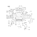
- FIG. 1 is a schematic cross-sectional view showing a configuration of a volume reduction processing system 1000 including a volume reduction processing apparatus 110 in the present embodiment.
- the volume reduction processing apparatus 110 of the volume reduction processing system 1000 includes a stage 112 in a vacuum container 114.
- the stage 112 is configured to place the supply of the resin 20 to be processed (the resin 22 to be processed) accompanied by a radioactive substance.
- a heater 116 is provided inside the flat plate portion on which the resin 22 to be treated of the stage 112 is placed, and the temperature of the stage 112 itself can be raised by the heater 116.
- At least one or both of the processed resin 22 itself heated by the stage 112 and the gas released from the processed resin 22 are oxidized by the oxygen plasma P.
- the CCP power supply system 180 can be used.
- the power (CCP power) supplied by the CCP power supply system 180 generates a voltage or an electric field in the space S above the stage 112 in the vacuum vessel 114 by capacitive coupling.
- the volume reduction processing device 110 is also equipped with an ICP power supply system 190.
- the volume reduction apparatus 110 is also provided with a supply mechanism 122 configured to supply the resin to be processed to the stage while maintaining the decompressed state of the empty container.
- the CCP power supply system 180 of the volume reduction processing device 110 continuously supplies the CCP power when the resin 20 to be treated is supplied to the stage 112 by the supply mechanism 122, thereby A voltage or electric field can be continuously applied to S.
- a high frequency coil 142 is disposed on the outer surface of the top wall 114R of the vacuum vessel 114 on the atmosphere side.
- the high frequency coil 142 is used to excite plasma in the space S inside the top wall 114 ⁇ / b> R of the vacuum vessel 114.
- the exhaust line 150 for keeping the inside in a reduced pressure state is also connected to the vacuum vessel 114.
- An exhaust valve 152 and a vacuum pump 154 are connected to the exhaust line 150.
- the opening degree of the exhaust valve 152 is controlled by the pressure control unit 158, and the pressure control unit 158 continuously performs control based on the signal of the pressure sensor 160 that measures the pressure in the internal space of the vacuum vessel 114. Yes. Therefore, the pressure control unit 158 automatically controls the pressure of the vacuum container 114 as APC (Automatic Pressure Controller).
- APC Automatic Pressure Controller
- a carbon dioxide sensor 156 is connected to the outlet side path of the vacuum pump 154.
- the carbon dioxide sensor 156 outputs concentration data or a concentration signal corresponding to the concentration of carbon dioxide gas measured in the exhaust path from the vacuum vessel 114.
- any type of gas sensor that achieves the purpose of measuring the concentration of the carbon-containing gas can be used in place of the carbon dioxide sensor 156.
- the same purpose can be achieved by using a carbon monoxide sensor instead of a carbon dioxide sensor.
- the gas sensor such as the carbon dioxide sensor 156 may be provided not on the outlet side path of the vacuum pump 154 but on, for example, a wall surface of the vacuum vessel 114 or a path to the vacuum pump 154 in the exhaust line 150. .
- the volume reduction processing apparatus 110 is provided with a radiometer 102.
- This radiometer 102 is an arbitrary radiometer designed to measure the radioactivity of the resin 20 to be processed before being supplied to the volume reduction processing device 110.
- a typical radiometer 102 may include a semiconductor detector that measures gamma rays by energy decomposition.
- the radiometer 102 outputs radioactivity data or a radioactivity signal indicating the radioactivity value of the resin 20 to be treated.
- the radiometer 102 is a radiometer having ⁇ -ray energy resolution, for example, the radioactivity in the specified nuclide can be measured while the radionuclide is specified by the energy of the emitted ⁇ -ray. It becomes possible.
- the arrangement of the radiometer 102 is not limited to the position shown in FIG. 1, and is arranged at an arbitrary position where the radioactivity value of the resin 20 to be processed can be acquired.
- the high frequency coil 142 is a coil formed by spirally forming a linear member such as copper.
- the high-frequency coil 142 has a connecting portion at a spiral center portion and a peripheral portion.
- the top wall 114 ⁇ / b> R of the vacuum vessel 114 is an insulator in order to generate a high-frequency electromagnetic field by the high-frequency coil 142 in the space S.
- the top wall 114R is made of fused silica glass. Note that the configuration and arrangement of the high-frequency coil that can be employed in the present embodiment are not particularly limited to the arrangement of the high-frequency coil 142.
- the volume reduction process of this embodiment can be performed by using a high-frequency coil having an arbitrary shape and arrangement suitable for excitation of oxygen plasma.
- the volume reduction processing apparatus 110 of the volume reduction processing system 1000 includes a CCP power supply system 180 and an ICP power supply system 190 as plasma power sources.
- FIG. 2 is a circuit diagram showing a configuration example of the CCP power supply system 180 and the ICP power supply system 190.
- the CCP power supply system 180 is connected to the high frequency coil 142 in combination with the ICP frequency blocking circuit 188 (the series resonance circuit 188A and the parallel resonance circuit 188B), whereas the ICP power supply system 190 is connected to the CCP frequency blocking circuit 188. It is connected to the high frequency coil 142 in combination with the circuit 198 (parallel resonant circuit 198A and parallel resonant circuit 198B).
- the CCP power supply system 180 includes a CCP high-frequency power source 186 that is a high-frequency power source having a CCP frequency of 13.56 MHz, for example, and a CCP matching circuit 184 for matching the output to the high-frequency coil 142. Yes. Of the two outputs of the CCP power supply system 180, one CCP output 180P is connected to the high-frequency coil 142 via the parallel resonance circuit 188B of the ICP frequency blocking circuit 188. On the other hand, the other CCP output 180N is grounded to GND. Since the vacuum vessel 114 is also grounded at GND and maintained at a ground level potential (FIG.
- the output of the CCP power supply system 180 passes between the high-frequency coil 142 and the vacuum vessel 114 through the top wall 114R.
- a voltage or electric field is applied to the space S. That is, the high-frequency coil 142 forms a capacitor that creates an electric field in the space S with a conductive member having the same potential as that of the vacuum vessel 114, and the voltage or electric field generated by the CCP power causes the plasma at the time of ignition to be generated. It works to improve the ease of firing and the stability of the excited plasma.
- the CCP matching circuit 184 includes variable capacitors CV1 and CV2 and reactance L1.
- the CCP matching circuit 184 acts to efficiently transmit the current output of the CCP high-frequency power source 186 to the high-frequency coil 142, for example, by changing the capacitances of the variable capacitors CV1 and CV2 as circuit constants.
- the ICP frequency blocking circuit 188 includes a series resonance circuit 188A and a parallel resonance circuit 188B. Among these, in the series resonance circuit 188A, the capacitor C1 and the reactance L2 are connected in series. In the parallel resonance circuit 188B, the variable capacitor CV4 and the reactance L3 are connected in parallel.
- the series resonance circuit 188A short-circuits the current of the frequency component of 2 MHz, that is, the ICP frequency component by series resonance, whereas the parallel resonance circuit 188B prevents the current of the ICP frequency component (2 MHz) from passing by the parallel resonance.
- the ICP frequency blocking circuit 188 including the series resonant circuit 188A and the parallel resonant circuit 188B has, for example, 2 MHz ICP frequency component power from the ICP power supply system 190 to the CCP power supply 182 and the CCP power supply system 180. It becomes the circuit which attenuates and stops.
- the ICP frequency blocking circuit 188 does not substantially act on CCP power having an ICP frequency such as 13.56 MHz, for example. That is, for the CCP power, the series resonance circuit 188A is the same as the open circuit, and the parallel resonance circuit 188B is the same as the short circuit.
- the blocking frequency of the parallel resonance circuit 188B is adjusted by changing the capacitance of the variable capacitor CV4.
- the reactance L2 and the reactance L3 are accompanied by parasitic resistance because they are actual reactance elements, and the energy of 2 MHz power in the resonance state is dissipated as Joule heat by the parasitic resistance.
- the ICP frequency blocking circuit 188 attenuates the power of the ICP frequency component from the ICP power supply system 190 toward the CCP power supply system 180.
- the ICP power supply system 190 includes, for example, an ICP high-frequency power source 196 that is a high-frequency power source with an ICP frequency of 2 MHz, and an ICP matching circuit 194 for matching the output with the high-frequency coil 142. I have. Of the two outputs of the ICP power supply system 190, one ICP output 190P and the other ICP output 190N are respectively connected to the two high-frequency coils 142 through the parallel resonant circuits 198A and 198B included in the CCP frequency blocking circuit 198. Is connected to one terminal. The output of the ICP power supply system 190 generates a high frequency electromagnetic field in the space S between the high frequency coil 142 and the vacuum vessel 114 through the top wall 114R.
- the ICP matching circuit 194 includes a variable capacitor CV3, a capacitor C2, and a variable reactance LV1.
- the capacity of the variable reactance LV1 is adjusted in order to efficiently transmit the current output of the ICP high frequency power source 196 to the high frequency coil 142.
- the CCP frequency blocking circuit 198 includes a parallel resonance circuit 198A connected to the ICP output 190P and a parallel resonance circuit 198B connected to the ICP output 190N.
- the parallel resonance circuit 198A is a parallel resonance filter for attenuating power of a component of a CCP frequency, for example, 13.56 MHz, by the variable capacitor CV5 and the reactance L4.
- the parallel resonance circuit 198B is also a parallel resonance filter for attenuating the CCP frequency component due to the variable capacitor CV6 and the reactance L5.
- the blocking frequencies of the parallel resonant circuit 198A and the parallel resonant circuit 198B are adjusted by changing the capacitances of the variable capacitor CV4 and the variable capacitor CV5.
- the reactances L4 and L5 are accompanied by parasitic resistance. For this reason, as in the case of the ICP frequency blocking circuit 188, the energy of the power of the CCP frequency (13.56 MHz) blocked by the parallel resonant circuit 198A and the parallel resonant circuit 198B is dissipated as Joule heat by the reactances L4 and L5. Is done. In this way, the CCP frequency blocking circuit 198 attenuates the power from the CCP power supply system 180 toward the ICP power supply system 190.
- the CCP frequency blocking circuit 198 does not substantially work for the ICP power. That is, for the ICP power that is an ICP frequency such as 2 MHz, for example, both the parallel resonant circuits 198A and 198B operate as a short circuit.
- both the CCP power supply system 180 and the ICP power supply system 190 are connected to the high-frequency coil 142.
- the high-frequency coil 142 capacitively couples the 13.56 MHz high-frequency power from the CCP power supply system 180 to the space S (FIG. 1) between the vacuum vessel 114 and the ground as one function. Act as an electrode for.
- the high-frequency coil 142 serves as an electrode for the grounded vacuum vessel 114, and a voltage or an electric field is generated in the space S by capacitive coupling.
- the operation of the CCP power supply system 180 is to increase the ease of starting the plasma with respect to the space or to increase the stability of the excited plasma by capacitive coupling using a voltage or an electric field.
- the capacitors C3 and C4 shown in FIG. 2 are provided for measuring the voltage by floating the high frequency coil 142 from the ground GND.
- the voltage output from the CCP power supply system 180 is high frequency by monitoring the peak-to-peak voltage amplitude VPP with respect to the ground GND of the electrode opposite to the grounded electrode of the floating capacitor C3. It is possible to measure the standard of the voltage applied to the space by the electrode of the coil 142.
- the high-frequency coil 142 acts as another coil that causes a current of 2 MHz high-frequency power from the ICP power supply system 190 to flow and generates an electric field and a magnetic field in the space S. .
- the action of the high-frequency coil 142 at this time is an action by inductive coupling with plasma as a conductor generated in the space.
- the action of the ICP power supply system 190 is an action of supplying power for increasing the plasma density to the space S by inductive coupling.
- the ICP output 190N is provided with a current measuring terminal. By measuring the peak current IP from here, a measure of the output current of the ICP power supply system 190 can be obtained.
- the ICP frequency blocking circuit 188 is connected to the CCP power supply system 180, and the CCP frequency blocking circuit 198 is connected to the ICP power supply system 190. These blocking circuits function to mitigate the effects of other power on the power supply. That is, the ICP frequency blocking circuit 188 prevents the CCP high-frequency power source 186 from being damaged by the power from the ICP power supply system 190 or the matching by the CCP matching circuit 184 from being stepped out. Similarly, the CCP frequency blocking circuit 198 prevents the ICP high-frequency power source 196 from being damaged by the power from the CCP power supply system 180 or the matching by the ICP matching circuit 194 from being stepped out.
- a typical volume reduction processing apparatus 110 (FIG. 1) according to this embodiment includes a supply mechanism 122.
- the resin 20 to be treated is supplied to the stage 112 by the supply mechanism 122 through the supply side gate valve G1.
- the supply mechanism 122 is provided with a quantitative mass 124 having a predetermined volume.
- the fixed mass 124 is delivered by the arm 126 to the position above the stage 112 through the opened supply-side gate valve G1.
- the resin 20 to be treated in the quantitative mass 124 is dropped onto the upper surface of the stage 112.
- a fixed mass driving mechanism 128 that enables such an operation is connected to the arm 126.
- the volume reduction apparatus 110 includes a vacuum vessel 114 that is generally formed in a cylindrical shape.
- Gas supply lines 130 ⁇ / b> A and 130 ⁇ / b> B for supplying oxygen to the internal space of the vacuum container 114 are connected to the vacuum container 114.
- Oxygen from the oxygen cylinder 132 is supplied from the gas supply lines 130A and 130B to the internal space of the vacuum vessel 114 through regulator valves 134A and 134B, respectively. Accordingly, at least the regulator valves 134A and 134B operate as a gas condition control unit that controls the supply condition of oxygen supplied to the internal space of the vacuum vessel 114.
- the regulator valves 134A and 134B can be calibrated as controlled by the computer 176 directly or through the sequence control unit 174.
- the computer 176 and the sequence control unit 174 also operate as a gas condition control unit.
- the stage 112 is a metal tray that is manufactured in the shape of a circular dish and on which the resin 22 to be treated can be placed.
- the stage 112 is configured to be able to rotate around an axis that passes through the center of the circular dish and is perpendicular to the flat plate portion while maintaining the airtightness of the vacuum vessel 114.
- the stage drive mechanism 118 can cause the stage 112 to perform a slow rotation operation, for example, once per several minutes to several times per minute.
- the stage 112 is manufactured so that the vertical position, that is, the height of the paper surface of FIG. 1 can be changed by a driving mechanism (not shown).
- the stage 112 is connected to a heating power source 120 that supplies controlled power to the heater 116.
- the stage 112 is equipped with a temperature sensor (not shown) that measures the temperature of the stage 112 itself.
- the electric power supplied to the heater 116 is controlled in accordance with the temperature measurement signal from the temperature sensor.
- the temperature of the stage 112 can be controlled to a temperature suitable for volume reduction processing such as 400 ° C. or 700 ° C., for example.
- the computer 176 starts and stops the exhaust operation of the vacuum vessel 114, changes the pressure command value used by the pressure control unit 158 for automatic control, starts the heating power source 120, adjusts the output, Various controls such as a stop and drive command for the discharge mechanism 162 are performed.
- the computer 176 receives data or signals from the volume reduction processing device 110, the radiometer 102, the carbon dioxide sensor 156, and the additional radiometer 172, and receives these data or signals for each control described above. Is used.
- FIG. 3 is an explanatory diagram of an index indicating the state of the volume reduction processing system 1000 (FIG. 3A), and an explanatory diagram illustrating a state of resin volume reduction by a weight reduction ratio (FIG. 3B). )).
- FIG. 3A shows the temperature of the stage 112 (curve 202) and the value of the carbon dioxide concentration obtained from the carbon dioxide sensor 156 (curve 204).
- curve 214 is the estimated weight reduction rate which estimated the mode of volume reduction of resin.
- the temperature of the stage 112 indicated by the curve 202 is a temperature indication value indicated by a temperature sensor provided in the stage 112 (not shown), and the numerical value is clearly indicated on the vertical axis.
- the curve 204 indicating the value of the carbon dioxide concentration output from the carbon dioxide sensor 156 shows only temporal behavior, and the scale of the value is an arbitrary unit.
- the value of the carbon dioxide concentration shown by the curve 204 is plotted linearly and the horizontal axis is such that the concentration is zero.
- the sub-batch is a processing unit obtained by further subdividing a batch of the resin 20 to be processed, which is a unit processing amount for volume reduction processing.
- the volume reduction processing by the volume reduction processing system 1000 is roughly divided into two processing phases, that is, a first phase (first processing) and a second phase (second processing). ing.
- first phase the stage 112 is heated to approximately 400 ° C.
- second phase the stage 112 is heated to approximately 700 ° C.
- these temperatures show finer temporal variations as shown by the curve 202.
- the treatment target of the volume reduction treatment system 1000 is an ion exchange resin used by a nuclear power generation facility or the like
- the resin 22 to be treated is an ion exchange resin and a radioactive substance accompanied by the ion exchange resin. And the remaining moisture.
- ion exchange resins used in nuclear power generation facilities are accompanied by adsorbing or holding radioactive substances including radioisotopes on themselves in the form of ions or corrosive organisms (cladding).
- the resin 22 to be processed is divided into several sub-batches and put into the vacuum vessel 114 and placed on the stage 112.
- the resin 22 to be treated is carbonized by being heated to about 400 ° C.
- This process is a process first performed on the resin 22 to be processed.
- a large amount of water vapor is released until the temperature reaches about 400 ° C.
- the resin 22 to be treated begins to release a large amount of decomposition gas.
- This release of cracked gas is close to a phenomenon in which general organic substances release cracked gas by heat.
- power for exciting the plasma P is supplied to the high-frequency coil 142.
- This power is a combination of 13.56 MHz high frequency power for capacitive coupling supplied by the CCP power supply system 180 and 2 MHz high frequency power for inductive coupling supplied by the ICP power supply system 190. Is.
- the decomposition gas released from the resin 22 to be treated is oxidized by the oxygen plasma P excited in the space above the stage 112, and a component that is susceptible to oxidation in the decomposition gas, such as a carbon component, is oxidized.
- the gas generated by oxidizing the decomposition gas by the oxygen plasma P, that is, the processing gas contains carbon dioxide and carbon monoxide. This processing gas is exhausted through the exhaust line 150.
- the decomposition in this process is intense immediately after the start of the process and starts to weaken after a certain period of time. This corresponds to the consumption of components that are decomposed by the temperature.
- the stage 112 is left with the decomposition gas component extracted from the resin 22 to be treated and carbonized.
- the decomposition treatment of the resin 22 to be treated, the carbonization treatment, and the oxidation treatment of the decomposition gas are performed by combining the heating of the stage 112 and the oxidation by the oxygen plasma P.
- the carbon component of the cracked gas in the first phase is discharged from the exhaust line 150 as carbon dioxide or carbon monoxide gas in the oxidized processing gas, and its concentration is measured by the carbon dioxide sensor 156.
- the carbon dioxide concentration in the first phase increases with increasing temperature in each sub-batch, and after a high value is maintained for a certain time, it decreases with consumption of the components to be decomposed.
- the value of the carbon dioxide concentration is a direct index indicating the amount of carbon per unit time that is oxidized in the resin 22 to be treated.
- the value of the carbon dioxide concentration is an indirect indicator for all components oxidized in the resin 22 to be treated.
- all the components oxidized in the to-be-processed resin 22 may contain a nitrogen component, a sulfur component, and a hydrogen component other than a carbon component.
- the resin 22 to be processed is processed in units of sub-batches in which the resin 22 to be processed is subdivided into the processing capacity range of the volume reduction processing device 110.
- FIG. 2A shows a state in which the resin 22 to be treated is put into four sub-batches.
- the progress of carbonization and decomposition treatment by heating on the first sub-batch of the resin 22 to be treated is monitored as the value of the carbon dioxide concentration.
- the supply-side gate valve G1 is opened, and the next sub-batch, that is, the second sub-batch treated resin 22 is additionally charged.
- the processed resin 22 that has been processed as the first sub-batch remains on the stage 112.
- a second sub-batch treated resin 22 is additionally supplied to the stage 112 in that state. Therefore, the resin 22 to be processed is processed in both the newly added second sub-batch and the first sub-batch being processed. Thereafter, the third sub-batch and the fourth sub-batch are similarly processed.
- the first phase of the resin 22 to be treated is advanced in this way because a large amount of cracked gas is generated from the resin 22 to be treated in the first phase compared to the second phase. This is because the ability to process may be insufficient.
- the second phase will be described.
- the vacuum vessel 114 remains decompressed without being released to the atmosphere.
- the pressure that is, the degree of vacuum is changed between the first phase and the second phase.
- the processing target of the second phase is a semi-processed product carbonized through the first phase processing as the first to fourth sub-batch of the resin 22 to be processed remaining on the stage 112.
- this half-processed product is also referred to as a resin 22 to be processed.
- the temperature of the stage 112 is raised to 700 ° C. in that state.
- the second phase is a process of further reducing the volume by reducing the carbon component of the resin 22 to be treated that has been carbonized by ashing that combines heat treatment and oxygen plasma.
- oxygen plasma P is used as in the first phase.
- the high-frequency coil 142 is supplied with electric power for exciting the plasma P by inductive coupling.
- oxidizing the cracked gas was an action expected of the oxygen plasma P
- the oxygen plasma was expected in the action of ashing the carbonized resin 22 to be treated. P is excited.
- the gas supply conditions are different for the first phase and the second phase. Most typically, a higher pressure than in the first phase is selected in the gas supply conditions in the second phase.
- the oxygen supply direction is also selected so that the airflow from the top wall 114R toward the stage 112 in the second phase is larger than that in the first phase.
- the carbon components remaining in the resin 22 to be treated are discharged from the exhaust line 150 as a treatment gas such as carbon dioxide or carbon monoxide gas. Is done.
- the carbon dioxide concentration in the second phase also increases as the temperature increases, and after a high value is maintained for a certain time, it decreases according to the consumption of the component to be oxidized.
- the value of the carbon dioxide concentration obtained from the carbon dioxide sensor 156 is a direct index indicating the amount of carbon per unit time oxidized in the resin 22 to be treated, This is an indirect indicator for all components oxidized in the resin 22 to be treated.
- the supply of the resin 20 to be processed (the resin 22 to be processed) is subjected to volume reduction processing while being placed on the stage 112.
- This volume reduction process is performed by a heat process by the stage 112 and an oxidation process by the oxygen plasma P. That is, the volume reduction treatment apparatus 110 heats the resin 22 to be treated, and oxidizes at least one or both of the resin 22 itself and the gas released from the resin 22 with the oxygen plasma P. .
- the volume reduction process is performed in the second phase, the solid content (residual solid matter) placed on the stage 112 is obtained from the resin 22 to be treated.
- the CCP power supply system 180 and the ICP power supply system 190 are stopped, the excitation of plasma is stopped, and the stage heating is also stopped, thereby stopping the volume reduction process.
- the residual solid is removed from the stage 112 by the discharge mechanism 162 and discharged to the outside of the vacuum container 114.
- a suction pipe 164 including a recovery nozzle 166 is disposed in the discharge mechanism 162.
- the suction pipe 164 is connected to a discharge drive mechanism 168 for driving the position of the recovery nozzle 166 to a position suitable for suction of the residual solid matter on the stage 112 in a state where the discharge side gate valve G2 is open.
- the residual solid sucked by the suction pipe 164 is recovered while preventing scattering through a bag filter or a cyclone (both not shown) for recovering the residual solid from the airflow, and is temporarily stored in the residual solid container 170. It is stored in.
- the residual solid container 170 is provided with an additional radiometer 172 for measuring the radioactivity remaining in the final residual solid.
- the solid residue in the solid residue container 170 is then sealed, for example, with cement or covered with sand to increase safety, and transported to a suitable facility such as a final disposal site for semi-permanent use. Is disposed of by permanent storage.
- the CCP power supply system 180 operates to generate a voltage or an electric field in the space S in the vacuum vessel 114 by capacitive coupling.
- This voltage or electric field has the effect of facilitating the ignition of the oxygen plasma.
- This voltage or electric field also has an arc extinguishing prevention effect that prevents arc excitation of the excited oxygen plasma.
- oxygen in a reduced pressure state is easily ionized and ionized. For this reason, oxygen easily turns into plasma.
- This reduced pressure state may be a pressure suitable for a decompression process described later, for example, a pressure of about 10 Torr.
- a pressure suitable for a decompression process described later for example, a pressure of about 10 Torr.
- the CCP power supply system 180 it is not necessary to reduce the pressure in the vacuum vessel 114 for the purpose of facilitating plasma ignition. If the plasma is ignited only by the ICP power supply system 190 without using the CCP power supply system 180, an equivalent voltage, that is, an electric field is not generated with the same power.
- the pressure region in which these devices normally operate is a region on the right side of the minimum value of the Paschen curve, that is, a region in which the voltage or electric field required for discharge increases as the pressure increases.
- the ICP power supply system 190 when only the ICP power supply system 190 is used, it is necessary to set a lower pressure in order to easily ignite the oxygen plasma. Furthermore, the ionization effect by the voltage or electric field which the CCP electric power supply system 180 brings with respect to the space S is useful also about arc-extinguishing prevention property.
- the ICP power supply system 190 functions to increase the density of the oxygen plasma P. Since high-density oxygen plasma P is generated by electromagnetic induction in the vicinity of the high-frequency coil 142, that is, directly below the top wall 114R, by the power from the ICP power supply system 190, the processing amount per unit time in the volume reduction processing, that is, the processing speed It is possible to increase.
- the densification is achieved by inductively coupling the conductivity indicated by ionized ions in the plasma with the power for ICP.
- the current in the high-frequency coil 142 is only increased.
- the CCP power is superimposed on the ICP power as in the present embodiment, an ionizing action is brought about even on oxygen molecules that have not been converted to plasma. For this reason, superimposing the CCP power on the ICP power helps to start the oxygen plasma and prevents the plasma once excited from extinguishing.
- the timing at which the plasma is ignited is the timing shown at time A in FIG. 3A, that is, the timing at which the first phase processing is started.
- the timing will be described in detail.
- a process of measuring the initial radioactivity is executed by the radiometer 102.
- the sub-batch (first sub-batch) resin 22 to be processed initially is opened by opening the supply-side gate valve G1, and the supply-side gate valve G1 is closed again.
- This is a process of supplying a constant volume of the resin 22 to be processed by the fixed mass 124 and is a process of placing the resin 22 to be processed on the stage 112 of the vacuum vessel 114 in advance as a first sub-batch.
- the inside of the vacuum container 114 is depressurized.
- a pressure of about 10 Torr (1.3 kPa) is selected as a pressure suitable for the volume reduction process in the first phase.
- the stage 112 is heated to 400 ° C. by the heater 116 in order to start the volume reduction process in the first phase.
- measurement of the carbon dioxide gas concentration by the carbon dioxide sensor 156 is started. Note that the order of raising the temperature of the stage and starting measurement of carbon dioxide gas may be reversed.
- the plasma is then ignited. In the volume reduction processing apparatus 110 of the present embodiment, it is possible to ignite plasma while automatically controlling the pressure suitable for the first phase processing described above.
- the CCP power supply system 180 starts to supply the power of the CCP frequency such as 13.56 MHz (CCP power) to the high-frequency coil 142. .
- this electric power acts to oscillate the voltage of the high-frequency coil 142 with respect to a grounded conductor portion such as the vacuum vessel 114 and the stage 112.
- the voltage acts as an electric field for the space S, and converts the introduced oxygen into plasma. In this way, the oxygen plasma is ignited.
- the output of the CCP power supply system 180 necessary for this is, for example, about 1 kW.
- the pressure is lowered below the pressure suitable for volume reduction processing, as in the conventional volume reduction processing apparatus, or the volume reduction processing is performed thereafter. Therefore, there is no need to return the pressure to the required pressure.
- ICP power is output from the ICP power supply system 190 in order to supply power by inductive coupling which is useful for increasing the plasma density.
- the output of the CCP power supply of the CCP power supply system 180 is increased to, for example, about 2 kW in order to stabilize the plasma excitation state.
- the output of the ICP power of the ICP power supply system 190 can be an arbitrary output.
- the CCP power supply system 180 outputs the CCP power to generate a voltage or an electric field in the space S at the same time, and at the same time, the ICP power from the ICP power supply system 190.
- the action of is applied to the space S. In this way, even if there is moisture released from the supplied first sub-batch of the resin 22 to be processed, the high-density oxygen plasma can stably maintain the plasma state.
- This action at time B1 works similarly even when the second sub-batch, the third sub-batch, and the fourth sub-batch of the resin 20 to be treated are additionally charged. These timings are clearly shown as times B2, B3, and B4 in FIG.
- the CCP power is output from the CCP power supply system 180, and at the same time, the ICP power is also output from the ICP power supply system 190. It becomes possible to stably excite the oxygen plasma.
- the supply-side gate valve G1 When the second to fourth sub-batches are charged, the supply-side gate valve G1 is opened, the resin 20 to be processed as each sub-batch is charged, and then the supply-side gate valve G1 is closed again. It is. Since both sides of the supply-side gate valve G1 are evacuated, even if the supply-side gate valve G1 is opened, the pressure in the vacuum vessel 114 does not change.
- the output of the carbon dioxide sensor 156 is monitored. For example, until the measured value of the concentration of carbon dioxide gas drops from the maximum value to about 90%, it is determined that the maximum value remains, and monitoring is continued. And if it is judged that it fell from the maximum value by, for example, less than 90%, the resin of the sub-batch next to the sub-batch being processed is additionally charged.
- the output of the CCP power by the CCP power supply system 180 is controlled in accordance with the progress of the processing based on the output of the carbon dioxide sensor 156 monitored in this way. It is also possible to do.
- the output of the CCP power by the CCP power supply system 180 is started by the time when the additional sub-batch is introduced, and the output is continued for a predetermined period determined based on the experiment. When the predetermined period has passed, the output of the CCP power by the CCP power supply system 180 is stopped.
- the stage 112 is in a state in which the supplied carbonized resin 22 is disposed.
- a process of ashing this is performed as the second phase process.
- the stage temperature is first raised to 700 ° C.
- the gas supply conditions are changed from those in the first phase to those in accordance with the processing conditions in the second phase.
- This change in the gas supply condition includes a change in various conditions such as a change in pressure inside the vacuum vessel 114 and a change in the flow rate and supply direction of oxygen gas.
- the gas supply conditions may include any of gas conditions that affect the stability of the plasma.
- the gas supply conditions changed in the first phase and the second phase include the pressure inside the vacuum vessel 114. This is because the pressures suitable for the volume reduction processing in the first phase and the second phase are different.
- the pressure in the second phase is set to about 10 Torr (1.3 kPa), for example.
- the pressure in the second phase is set to, for example, 30 to 50 Torr (about 4.0 to 6.7 kPa).
- the pressure is suddenly changed when the pressure is different between the first phase and the second phase, the plasma is extinguished with the conventional method in which the oxygen plasma is excited only by the ICP power. The probability that it will be increased.
- the pressure is changed stepwise or continuously from the pressure in the first phase to the pressure in the second phase.
- the output of the CCP power by the CCP power supply system 180 is used for the ICP by the ICP power supply system 190. Use with power output.
- the combined operation of the CCP power and the ICP power supply makes it possible to stably maintain the plasma excitation state even if the pressure is suddenly changed.
- the output of the CCP power supply system 180 necessary for this is, for example, about 1 kW.
- the pressure of the vacuum vessel 114 is controlled by changing the pressure command value that the pressure control unit 158 performs automatic control as APC.
- the oxygen gas supply direction patterns are different from each other. That is, in the first phase, oxygen is supplied mainly by a swirl flow pattern, whereas in the second phase, oxygen is supplied by a pattern that combines the swirl flow component and the concentrated flow component that gathers toward the axis. Is done.
- the swirl flow is generally an orientation along the inner wall of the cylinder and substantially along the surface included in the stage 112 in the vacuum vessel 114 made in a cylindrical shape coaxial with the central axis of the stage 112. In the cylindrical space S, the oxygen gas vortex is generated so as to be generated.
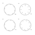
- FIG. 4 is a horizontal sectional view of the vacuum vessel 114, showing a swirling flow (FIG. 4A), a concentrated flow (FIG. 4B), and a first phase air flow (first pattern, FIG. 4C). And a second phase airflow (second pattern, FIG. 4D). Due to the introduction of these gases, the inner wall of the vacuum vessel 114 has a number of orientations that turn around one direction along the circumference for swirl flow and towards the axis for concentrated flow. A gas inlet is provided. In FIG.
- the introduction direction from the gas supply line 130 ⁇ / b> A is drawn in a direction toward the paper surface on the left inner surface of the vacuum container 114, and in a direction protruding from the paper surface on the right inner surface of the vacuum container 114. Further, the introduction direction from the gas supply line 130B is drawn in a direction from the inner surface of the vacuum vessel 114 toward the center.
- the flow rate for each gas inlet is realized by adjusting the open / close state and flow rate of the regulator valve 134A for swirl flow and the regulator valve 134B for concentrated flow included in the gas supply line 130A or 130B. Is done.
- oxygen gas is supplied by these patterns.
- the main volume reduction process is to oxidize the decomposition gas released from the supplied resin 22 to be treated.
- the first-phase oxygen plasma a process for oxidizing the decomposition gas as efficiently as possible is performed.
- the direction of the oxygen gas is swirled (FIG. 4 (c)).
- the supplied resin 22 to be treated is in a carbonized state, and the main treatment is ashing the carbonized residue solid.
- the reason why the swirl flow component remains in the second phase pattern is that if the flow rate of oxygen suitable for volume reduction treatment is supplied only by the concentrated flow, the downflow becomes too strong. In other words, by combining the swirl flow with the concentrated flow, an appropriate down flow is actually performed while supplying oxygen at a flow rate suitable for volume reduction treatment. In order to set the oxygen supply pattern in this way, the ratio of the concentrated flow and the swirling flow is adjusted.
- oxygen plasma when oxygen plasma is excited as IC plasma by the output of the ICP power supply only by the ICP power supply system 190, it is excited as IC plasma when the oxygen supply pattern is rapidly changed.
- the oxygen plasma that is present can extinguish.
- the possibility of extinguishing the plasma is not completely eliminated.
- the output of the CCP power from the CCP power supply system 180 is used in addition to the output of the ICP power supply from the ICP power supply system 190, the timing of changing the direction of oxygen supply is used. It is possible to reduce the possibility that the plasma is extinguished. Therefore, the conventional process of changing the direction of supplying oxygen stepwise or continuously is not necessary. For example, even if the oxygen supply pattern is suddenly changed from a swirl flow pattern suitable for the first phase to a combination of swirl flow and concentrated flow suitable for the second phase, the plasma is stably excited. It is possible to maintain the state.
- the CCP power is output from the CCP power supply system 180 when the ignition timing of the plasma, the timing of additional charging of the resin to be treated in the first phase, and the first phase. At any or all of the timing of the transition to the second phase.
- the CCP power output from the CCP power supply system 180 output at any one of these timings acts as a voltage or an electric field on the space S, thereby facilitating plasma ignition and preventing arc extinction.
- the CCP power supply system 180 is operated by appropriately selecting some or all of these timings as necessary.
- the CCP power supply system 180 may be operated so as to continuously output the CCP power.
- One of the effects is that unexpected arc extinction of oxygen plasma can be prevented in advance as in the above-described operation at each timing.
- Another effect is that the processing speed can be increased as compared with the case where only the output of the ICP power supply from the ICP power supply system 190 is used.
- the effect of increasing the processing speed is related to the fact that the oxygen flow rate is conventionally limited only by IC plasma. If the output of the CCP power from the CCP power supply system 180 of the present embodiment is used, the stability of the plasma is increased. It becomes possible to make it. As a result, it is possible to increase the oxidation rate of the decomposition gas or the supplied solid residue of the resin 22 to be processed, and the processing rate by the volume reduction processing device 110 can be increased.
- the timing for outputting the CCP power from the CCP power supply system 180 is an arbitrary timing for performing the processing of the first phase and the second phase.
- the CCP power is output from the CCP power supply system 180 in any period from time B1 to time B2, as shown in FIG. 3A, in any period from time B2 to time B3, and In any period from time B3 to time B4, it is an arbitrary part or all of the period. If the CCP power supply system 180 outputs the CCP power during any of these periods, the processing speed when oxidizing the cracked gas in the first phase can be increased. As another period, it is also useful to output the CCP power from the CCP power supply system 180 at an arbitrary timing after the time C. If the CCP power supply system 180 outputs the CCP power in an arbitrary period after the time C, it is possible to increase the processing speed when oxidizing the residual solids of the resin 22 to be processed supplied in the second phase. become.
- Example An example of an operable volume reduction processing apparatus 110 according to the above-described embodiment was produced. Specifically, the CCP power supply system 180 and the ICP power supply system 190 shown in FIG. It should be noted that the circuit constants of the component parts described in Table 1 include those that are adapted to the necessary circuit constants by combining not actual components but individual components.
- the capacitor C2 (2500 pF) used in the ICP matching circuit 194 can be implemented by a combined capacitance realized by connecting two 1000 pF capacitors and one 500 pF capacitor in parallel.
- the oxygen plasma P is actually easily ignited and the stability of the excited oxygen plasma P is reduced. Evaluated. As a result, it was possible to easily ignite the oxygen plasma P as compared with the case where only the ICP power supply system 190 was used without using the CCP power supply system 180. Specifically, it is output from the CCP power supply system 180 to the high-frequency coil 142 while maintaining the pressure of 10 Torr (1.3 kPa) without having to lower the pressure of the vacuum vessel 114 for ignition. The oxygen plasma P could be ignited by setting the output of 56 MHz to about 1 kW.
- the output from the CCP power supply system 180 is increased to about 2 kW, and the 2 MHz output output from the ICP power supply system 190 to the high frequency coil 142 is increased to about 3 kW.
- a high-density plasma was generated and the volume reduction treatment could be performed. This plasma was not only easily ignited at time A (FIG. 3) of the first phase, but was also stably excited without being extinguished at any time B1, B2, B3 and B4.
- the pressure in the vacuum vessel 114 is increased to 50 Torr (about 6.7 kPa), and the regulator valve 134A and the regulator valve 134B are controlled to change the swirl flow from the swirl flow. It was changed to a combination with a concentrated flow. Even at the time C, the excited plasma was not extinguished, and it was possible to continue exciting the stable plasma.
- FIG. 5 is an explanatory diagram showing the configuration of a plurality of electrodes arranged on the atmosphere side surface of the top wall 114R of the vacuum vessel 114 and the state of connection of the CCP power supply system and the ICP power supply system to them. is there.
- FIG. 5 is an explanatory diagram showing the configuration of a plurality of electrodes arranged on the atmosphere side surface of the top wall 114R of the vacuum vessel 114 and the state of connection of the CCP power supply system and the ICP power supply system to them. is there.
- a disk electrode 144 is disposed at the center of the high frequency coil 142 connected to the ICP power supply system 190A, and the CCP power from the CCP power supply system 180A is applied to the disk electrode 144.
- An example of output is shown.
- a ring electrode 146 is disposed on the outer periphery of the high-frequency coil 142 connected to the ICP power supply system 190B, and the CCP power from the CCP power supply system 180B is supplied to the ring electrode 146.
- An example of output is shown.
- the current as the outputs of the ICP power supplies 192A and 192B from the ICP power supply systems 190A and 190B flows through the high-frequency coil 142, so that the space S Has the effect of increasing the density of the plasma.
- the high frequency coil 142 is used only for inductively coupling the ICP power to the space S, it functions only as an ICP coil.
- the output of the CCP power from the CCP power supply 182A of the CCP power supply system 180A is the space S between the disk electrode 144 and the vacuum vessel 114. It acts as a voltage or an electric field to facilitate plasma ignition and to stabilize the plasma.
- the output of the CCP power from the CCP power supply 182B of the CCP power supply system 180B is between the ring electrode 146 and the vacuum vessel 114.
- An action that acts as a voltage or an electric field on the space S to facilitate the ignition of the plasma and an action to stabilize the plasma are realized.
- the vacuum vessel 114 is also grounded at GND and maintained at a ground level potential (FIG. 1), the disc electrode 144 or the ring electrode 146 is not spaced from the conductive member at the same potential as the vacuum vessel 11. It is a capacitor that creates an electric field in S.
- the CCP power supply from the CCP power supply system 180A or 180B when the CCP power supply from the CCP power supply system 180A or 180B is output to an electrode different from the high frequency coil 142, the CCP power supply system 180A or 180B and the ICP power supply are supplied. Both outputs of system 190A or 190B will not be directly connected to each other.
- the CCP when an electrode different from the high-frequency coil 142 is used, depending on the specific configuration of the high-frequency coil 142 and the disk electrode 144 or the specific configuration of the high-frequency coil 142 and the ring electrode 146, the CCP.
- the mutual influence between the power supply 182A or 182B for power supply and the power supply 192A or 192B for ICP is reduced.
- the ICP frequency blocking circuit 188 and the CCP frequency blocking circuit 198 shown in FIG. 2 are omitted or changed to a simple configuration.
- the influence of the CCP power source 182A or 182B and the ICP power source 192A or 192B on each other may be affected. It may still be a problem.
- a modification using only one of the disk electrode 144 and the ring electrode 146 is shown. Which of these is used is appropriately selected in consideration of, for example, the electric field strength generated in the space S, the strength of the CCP power input to the plasma, and the like. Also, both the disc electrode 144 and the ring electrode 146 are provided to supply power for CCP to them, or another form of electrode is provided at another position where an electric field is generated in the space S. This embodiment also includes supplying CCP power.
- the present invention makes it easy to reduce the volume of waste discharged from the operation of nuclear facilities by providing a volume reduction apparatus capable of stably performing resin treatment and an operation method thereof.
Landscapes
- Physics & Mathematics (AREA)
- Engineering & Computer Science (AREA)
- Plasma & Fusion (AREA)
- General Engineering & Computer Science (AREA)
- High Energy & Nuclear Physics (AREA)
- Electromagnetism (AREA)
- Spectroscopy & Molecular Physics (AREA)
- Chemical & Material Sciences (AREA)
- Analytical Chemistry (AREA)
- Environmental & Geological Engineering (AREA)
- Plasma Technology (AREA)
- Physical Or Chemical Processes And Apparatus (AREA)
Abstract
Description
[1 システム構成]
図1は、本実施形態における減容処理装置110を含む減容処理システム1000の構成を示す概略断面図である。
減容処理システム1000の減容処理装置110には、ステージ112が真空容器114内に備えられている。このステージ112は、放射性物質を伴っている被処理樹脂20の供給されたもの(被処理樹脂22)を載置するようになっている。また、ステージ112の被処理樹脂22が置かれる平板部分の内部には、ヒーター116が設けられており、そのヒーター116によってステージ112自体の温度が昇温可能となるようにされている。ステージ112によって加熱されている被処理樹脂22それ自体や、被処理樹脂22から放出されるガスは、少なくともいずれかまたは両方が酸素プラズマPによって酸化される。その酸素プラズマPを点弧させるために、CCP用電力供給系180を利用することができる。このCCP用電力供給系180により供給される電力(CCP用電力)は、真空容器114内のステージ112の上方の空間Sに容量結合により電圧または電界を生じさせる。また、減容処理装置110には、酸素プラズマPに対して誘導結合により電力を供給するために、ICP用電力供給系190も装備されている。さらに、減容処理装置110には、空容器の減圧状態を維持したままステージに被処理樹脂を供給するようになっている供給機構122も備わっている。
高周波コイル142は、例えば銅などの線状部材を渦巻き状に形成したよるコイルである。高周波コイル142は、渦巻き状の中心部と周縁部とに接続部を有している。
減容処理システム1000の減容処理装置110には、プラズマ用電源として、CCP用電力供給系180と、ICP用電力供給系190とが備えられている。図2は、CCP用電力供給系180とICP用電力供給系190との構成例を示す回路図である。CCP用電力供給系180は、ICP周波数阻止回路188(直列共振回路188Aおよび並列共振回路188B)と組み合わせて高周波コイル142に接続されているのに対し、ICP用電力供給系190は、CCP周波数阻止回路198(並列共振回路198Aおよび並列共振回路198B)と組み合わせて高周波コイル142に接続されている。
CCP用電力供給系180は、例えば13.56MHzであるCCP用周波数の高周波電源であるCCP用高周波電力源186と、その出力を高周波コイル142にマッチングさせるためのCCP用マッチング回路184とを備えている。CCP用電力供給系180の二つの出力のうち、一方のCCP出力180Pは、ICP周波数阻止回路188の並列共振回路188Bを介して高周波コイル142に接続されている。これに対し、他方のCCP出力180Nは、GNDに接地されている。なお、真空容器114もGND接地されて接地レベルの電位に保たれているため(図1)、CCP用電力供給系180の出力は、頂部壁114Rを通じて高周波コイル142と真空容器114との間の空間Sに対する電圧または電界を与える。つまり、高周波コイル142は、真空容器114と等しい電位にある導電性の部材との間で空間Sに電界をつくるキャパシターをなしており、CCP用電力による電圧または電界が、点弧時のプラズマの点弧容易性や、励起されているプラズマの安定性を向上させるように作用する。
これに対して、ICP用電力供給系190は、例えば2MHzのICP用周波数の高周波電源であるICP用高周波電力源196と、その出力を高周波コイル142にマッチングさせるためのICP用マッチング回路194とを備えている。ICP用電力供給系190の二つの出力のうち、一方のICP出力190Pおよび他方のICP出力190Nは、それぞれ、CCP周波数阻止回路198に含まれている並列共振回路198Aおよび198Bを通じて高周波コイル142の二つの端子部に接続されている。ICP用電力供給系190の出力は、頂部壁114Rを通じて高周波コイル142と真空容器114との間の空間Sに対して高周波電磁界を生成する。
上述したように、本実施形態の減容処理装置110においては、高周波コイル142に対し、CCP用電力供給系180とICP用電力供給系190との両者が接続されている。したがって、高周波コイル142は、一つの作用として、接地されている真空容器114との間の空間S(図1)に対してCCP用電力供給系180からの13.56MHzの高周波電力を容量結合させるための電極として作用する。この場合の高周波コイル142が接地されている真空容器114に対する電極となって、容量結合により電圧または電界を上記空間Sに生じさせる。CCP用電力供給系180の作用は、電圧または電界による容量結合により、上記空間に対してプラズマの点弧容易性を高めたり、励起されているプラズマの安定性を高めたりする作用である。なお、図2に示したキャパシターC3およびC4は、高周波コイル142を接地GNDから高周波コイル142をフローティングさせて電圧を測定するために設けられている。すなわち、CCP用電力供給系180による出力の電圧は、フローティング用のキャパシターC3の接地している電極とは反対の電極の接地GNDに対するピーク・トゥー・ピークでの電圧振幅VPPをモニターすれば、高周波コイル142の電極が空間に与えている電圧の目安を測定することが可能となる。
上述したように、CCP用電力供給系180にはICP周波数阻止回路188が、また、ICP用電力供給系190にはCCP周波数阻止回路198が接続されている。これらの阻止回路は、互いに他の電力が電源に及ぼす影響を軽減するように機能する。つまり、ICP周波数阻止回路188は、ICP用電力供給系190からの電力によってCCP用高周波電力源186が破損したり、CCP用マッチング回路184によるマッチングが脱調したりすることを防止する。同様に、CCP周波数阻止回路198は、CCP用電力供給系180からの電力によってICP用高周波電力源196が破損したり、ICP用マッチング回路194によるマッチングが脱調したりすることを防止する。
本実施形態の典型的な減容処理装置110(図1)には供給機構122が備わっている。被処理樹脂20は、供給機構122によって供給側ゲートバルブG1を通ってステージ112に供給される。その供給動作を行うために、供給機構122は所定の容積に作製された定量マス124を備えている。被処理樹脂20を供給するためには、まず、開かれた供給側ゲートバルブG1を通ってステージ112の上方空間の位置にまで定量マス124がアーム126によって届けられる。次に、その位置で定量マス124をアーム126の軸回りに回転させることにより、定量マス124内の被処理樹脂20をステージ112の上面に落下させる。このような動作を可能にする定量マス駆動機構128がアーム126には接続されている。
減容処理装置110は、概して円筒形状に作製されている真空容器114を備えている。その真空容器114には、真空容器114の内部空間に対して酸素を供給するためのガス供給ライン130Aおよび130Bが接続されている。このガス供給ライン130Aおよび130Bからは、それぞれ、レギュレータバルブ134Aおよび134Bを通じて、酸素ボンベ132からの酸素が真空容器114の内部空間へと制御された流量によって供給される。したがって、少なくともレギュレータバルブ134Aおよび134Bは、真空容器114の内部空間へと供給される酸素の供給条件を制御するガス条件制御部として動作している。また、本実施形態の減容処理装置110を含む減容処理システム1000では、レギュレータバルブ134Aおよび134Bが、コンピューター176によって直接またはシーケンス制御部174を通じて制御しているように校正することも可能である。その場合、コンピューター176やシーケンス制御部174も、ガス条件制御部として動作することとなる。
ステージ112は、円形皿の形状に作製されており、その上面に被処理樹脂22を載置することができるようになっている金属製のトレイである。このステージ112は、真空容器114の気密を維持したまま、円形皿の中心を通り平板部分に垂直な軸の周りに回転動作が可能となるように構成されている。ステージ駆動機構118は、例えば数分間に1回から一分間に数回程度のゆっくりした回転動作をステージ112に行なわせることが可能である。また、ステージ112は、図示しない駆動機構によって、図1の紙面の上下方向の位置つまり高さを変更することができるように作製されている。ステージ112には、制御した電力をヒーター116に供給する加熱用電源120が接続されている。温度制御のため、ステージ112には、ステージ112自体の温度を測定する温度センサー(図示しない)を装備している。この温度センサーからの温度測定信号に応じて、ヒーター116へ供給される電力が制御される。特に限定するものではないが、ステージ112の温度は、例えば400℃、あるいは、700℃といった減容処理に適する温度に制御することが可能である。
次に、上述した減容処理システム1000の減容処理装置110の動作について説明する。図3は、減容処理システム1000の状態を示す指標の説明図(図3(a))と、樹脂の減容の様子を減重率(weight reduction ratio)によって示す説明図(図3(b))である。減容処理システム1000の状態の指標として図3(a)に示したものは、ステージ112の温度(曲線202)と、二酸化炭素センサー156から得られる二酸化炭素濃度の値(曲線204)である。また、図3(b)に示したものは、樹脂の減容の様子を推定した推定減重率(曲線214)である。
図3(a)に示すように、減容処理システム1000による減容処理は、大別して、二つの処理フェーズ、すなわち第1フェーズ(第1処理)と第2フェーズ(第2処理)とに分かれている。第1フェーズでは、ステージ112が概ね400℃程度に加熱されるのに対し、第2フェーズではステージ112が概ね700℃程度に加熱される。なお、これらの温度は、曲線202に示したように、より細かい時間的な変動を示す。ここで、例えば減容処理システム1000の処理対象物が原子力発電設備などによって利用されたイオン交換樹脂である場合、被処理樹脂22は、イオン交換樹脂と、そのイオン交換樹脂が伴っている放射性物質と、残留している水分との混合物である。また、原子力発電設備において利用されるイオン交換樹脂は、放射性同位元素を含む放射性物質を、イオンまたは腐食性生物(クラッド)の形態でそれ自体に吸着または保持することにより伴っている。
上述した全体的な動作を実現するために、減容処理装置110においては、第1フェーズの開始時にプラズマを点弧する必要がある。また、励起されているプラズマの消弧を防止するためには、プラズマの励起状態を安定させる必要がある。本実施形態に採用されるCCP用電力供給系180とICP用電力供給系190とによる動作をこれらに関連して説明する。
まず、本願の発明者が考えるCCP用電力供給系180の作用について説明する。上述したように、CCP用電力供給系180は、容量結合によって真空容器114内の空間Sに電圧または電界を生じさせるように動作する。この電圧または電界は、酸素プラズマの点弧を容易にする点弧容易化の効果を有している。また、この電圧または電界は、励起されている酸素プラズマの消弧を防止する消弧防止の効果をも有している。具体的には、空間Sに電圧または電界が生成されると、減圧状態にある酸素は容易に電離してイオン化する。このため酸素は容易にプラズマ化する。この減圧状態は、後述する減圧処理に適する程度の圧力、例えば、10Torr程度の圧力であっても構わない。つまりCCP用電力供給系180を動作させれば、プラズマの点弧を容易にする目的で真空容器114の圧力を低下させる必要はない。なお、仮にCCP用電力供給系180を利用せず、ICP用電力供給系190のみによってプラズマを点弧しようとした場合には、同じ電力では同等の電圧つまり電界が生成されない。また、通常これらの装置が動作する圧力領域は、パッシェンカーブの最小値より右側の領域、つまり、放電のために要する電圧または電界が圧力の上昇とともに上昇する領域である。これらの理由から、ICP用電力供給系190のみを用いた場合には、酸素プラズマを容易に点弧するために、より低い圧力とする必要がある。さらに、消弧防止性についても、空間Sに対してCCP用電力供給系180がもたらす電圧または電界による電離作用が役に立っている。
次に、ICP用電力供給系190の作用について説明する。このICP用電力供給系190は、酸素プラズマPを高密度化するように働く。ICP用電力供給系190による電力によって高周波コイル142の近傍つまり頂部壁114Rの直下には電磁誘導によって高い密度の酸素プラズマPが生成されるため、減容処理における単位時間あたりの処理量すなわち処理速度を高めることが可能である。
そして、CCP用電力供給系180とICP用電力供給系190とを同時に動作させると、高周波コイル142には、CCP用電力供給系180からの電力(CCP用電力)と、ICP用電力供給系190からの電力(ICP用電力)とが重畳して投入される。これは、最終的には、CCP用電力による電圧または電界と、ICP用電力による電磁誘導とが空間Sに対して同時に作用する状態を作り出す。ここで、空間Sにおいて誘導結合のみによって励起されるICプラズマが生成されている従来の場合、ICP用電力は、プラズマを高密度化する作用を持つ。ところがその高密度化は、プラズマ中の電離したイオンの示す導電性がICP用電力と誘導的に結合して達成される。逆に、プラズマが点弧されていない状態や消弧してしまった状態では、ICP用電力を高めても、高周波コイル142における電流を増大させるばかりとなってしまう。これに対し、本実施形態のようにCCP用電力をICP電力に重畳して投入すると、プラズマ化していない酸素分子に対しても電離作用をもたらす。そのため、CCP用電力をICP用電力に重畳させると、酸素プラズマの点弧を助けるとともに、一旦励起されたプラズマの消弧を防止する役割を果たす。
プラズマを点弧するタイミングは、図3(a)の時間Aに示すタイミング、すなわち、第1フェーズの処理を開始するタイミングである。そのタイミングを詳細に説明すると、まず減容処理の最初の処理として、放射能計102によって、初期の放射能を測定する処理が実行される。次いで、供給側ゲートバルブG1を開放して初期に投入されるサブバッチ(第1サブバッチ)の被処理樹脂22が供給され、再び供給側ゲートバルブG1が閉止される。これは、定量マス124によって定容積の被処理樹脂22を供給する処理であり、第1サブバッチとしてあらかじめ真空容器114のステージ112に被処理樹脂22を載置する処理である。その後、真空容器114内が減圧される。その圧力は、例えば、第1フェーズの減容処理に適する圧力として、10Torr(1.3kPa)程度の圧力が選択される。目的の圧力に到達すると、第1フェーズの減容処理を開始するために、ステージ112がヒーター116によって400℃に昇温される。次いで、二酸化炭素センサー156による二酸化炭素ガス濃度の計測が開始される。なお、ステージの昇温と二酸化炭素ガスの計測開始の順序は逆であっても構わない。その後プラズマが点弧される。本実施形態の減容処理装置110においては、上述した第1フェーズの処理に適する圧力に自動制御したままプラズマを点弧することが可能である。
処理を開始すると、二酸化炭素ガスの濃度は、図3(a)の曲線204に示したように変化する。時間A以降は、供給された被処理樹脂22の第1サブバッチが処理されている。この処理を開始すると、二酸化炭素ガスの濃度が次第に増加し、その後、最大値となった後、今度は当該濃度が低下し始める。ここで、二酸化炭素ガスの濃度が増加する段階である時間B1においては、供給された被処理樹脂22の第1サブバッチから多量の水分(図示しない)が水蒸気となって放出されており、この水分が励起されている酸素プラズマPの安定性に悪影響を与える。本実施形態においては、この際にも、CCP用電力供給系180からCCP用電力を出力して空間Sに電圧または電界を生成させておき、同時に、ICP用電力供給系190からのICP用電力による作用を空間Sに作用させる。こうして、供給された被処理樹脂22の第1サブバッチから放出される水分が存在しても、高い密度の酸素プラズマは安定してプラズマ状態を維持することが可能となる。
第1フェーズの処理が完了すると、ステージ112には、供給された被処理樹脂22の炭化したものが配置された状態になっている。本実施形態の減容処理装置110においては、第2フェーズの処理としてこれを灰化する処理が行われる。そのためには、まず、ステージの温度が700℃に昇温される。次に、ガスの供給条件が、第1フェーズのものから第2フェーズの処理条件にあわせたものに変更される。このガスの供給条件の変更には、真空容器114内部の圧力変更といった各種の条件の変更と、酸素ガスの流量や供給方向の変更とを含んでいる。なお、ガスの供給条件は、プラズマ条件のうち、プラズマの安定性に影響するようなガスに関する任意の条件を含むことができる。
本実施形態において、第1フェーズと第2フェーズとにおいて変更されるガスの供給条件には、真空容器114の内部の圧力が含まれている。これは第1フェーズと第2フェーズのそれぞれの減容処理に適する圧力が異なるためである。本実施形態においては、第2フェーズの圧力は、例えば約10Torr(1.3kPa)に設定される。これに対して、第2フェーズの圧力は、例えば30~50Torr(約4.0~6.7kPa)に設定される。
第1フェーズと第2フェーズとにおけるガスの供給条件では、酸素ガスの供給方向のパターンが互いに異なっている。つまり、第1フェーズでは、主として旋回流のパターンにより酸素が供給されるのに対し、第2フェーズでは、その旋回流成分と、軸に向かって集まる集中流成分とを組み合わせたパターンにより酸素が供給される。ここで、旋回流とは、概して、ステージ112の中心軸と同軸の円筒形状に作製されている真空容器114において、円筒の内側壁に沿い、ほぼステージ112含まれる面に沿うような向きであり、その円筒形の空間Sにおいて酸素ガスの渦が生成されるように向かう向きである。また、軸に向かって集まる集中流成分とは、真空容器114の内壁からステージ112の軸に向かう向きの成分である。図4は、真空容器114の水平断面図によって、旋回流(図4(a))と集中流(図4(b))と、第1フェーズの気流(第1パターン、図4(c))と、第2フェーズの気流(第2パターン、図4(d))とを説明する説明図である。これらのガスの導入のために、真空容器114の内壁には、旋回流のために周に沿った一方向周りに回る向きに向けて、また、集中流のためには軸に向けて、いくつかのガス導入口が設けられている。図1においては、ガス供給ライン130Aからの導入方向が、真空容器114の左側内側面で紙面に向かう向きに、また、真空容器114の右側内側面で紙面から飛び出す向きに描かれている。また、ガス供給ライン130Bからの導入方向は、真空容器114の内側面から中央に向かう向きに描かれている。また、各ガス導入口に対する流量は、ガス供給ライン130Aまたは130Bに含まれている旋回流のためのレギュレータバルブ134Aおよび集中流のためのレギュレータバルブ134Bそれぞれの開閉状態と流量と調整することによって実現される。
上述した本実施形態において、CCP用電力供給系180からCCP用電力が出力されるのは、プラズマの点弧のタイミング、第1フェーズにおける被処理樹脂の追加投入のタイミング、そして、第1フェーズから第2フェーズへの移行のタイミングのうちのいずれかまたはすべてにおいてである。これらのいずれかのタイミングにおいて出力されるCCP用電力供給系180からのCCP用電力は、空間Sに電圧または電界として作用して、プラズマの点弧を容易にし、また、消弧を防止する効果を発揮する。必要に応じ、これらのタイミングのうちの一部または全部を適宜に選択してCCP用電力供給系180を動作させることは、本実施形態に含まれている。
上述した実施形態に従う動作可能な減容処理装置110の実施例を作製した。具体的には、図2に示したCCP用電力供給系180およびICP用電力供給系190を、表1に示す回路部材によって作製した。
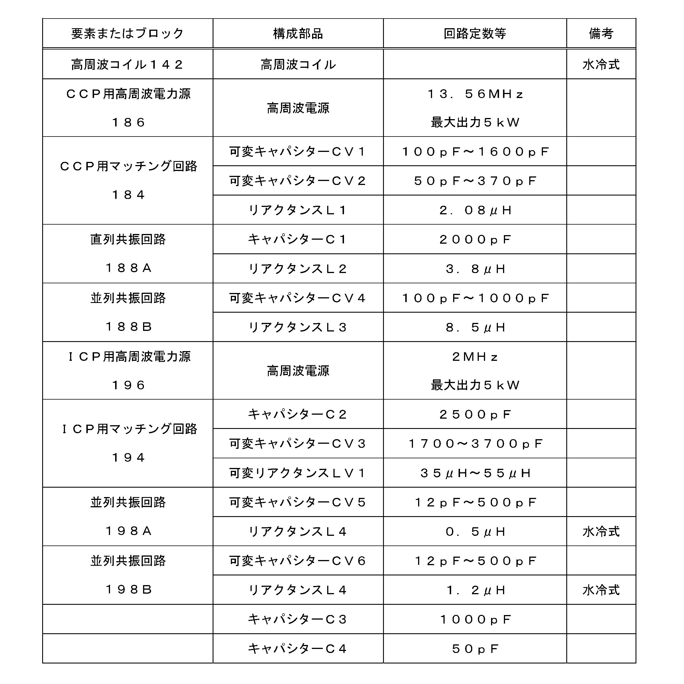
本発明の上述した第1実施形態はその趣旨を保って種々変形することが可能である。特に、容量結合による電圧または電界を空間Sにおいて生成するために、高周波コイル142とは別の電極を通じてCCP用電力供給系180からのCCP用電力の出力を空間S(図1)に作用させるように構成することも可能である。図5は、真空容器114の頂部壁114Rの大気側の面に配置される複数の電極の構成と、それらに対するCCP用電力供給系およびICP用電力供給系の接続の様子とを示す説明図である。図5(a)は、ICP用電力供給系190Aに接続された高周波コイル142の中心部に円板電極144を配置し、その円板電極144にCCP用電力供給系180AからのCCP用電力を出力する例を示している。また、図5(b)は、ICP用電力供給系190Bに接続された高周波コイル142の外周部にリング電極146を配置し、そのリング電極146にCCP用電力供給系180BからのCCP用電力を出力する例を示している。
20 被処理樹脂
22 供給された被処理樹脂
102 放射能計
110 減容処理装置
112 ステージ
114 真空容器
114R 頂部壁
116 ヒーター
118 ステージ駆動機構
120 加熱用電源
122 供給機構
124 定量マス
126 アーム
128 定量マス駆動機構
130A、130B ガス供給ライン
132 酸素ボンベ
134A、134B レギュレータバルブ
142 高周波コイル
144 円板電極
146 リング電極
150 排気ライン
152 排気バルブ
154 真空ポンプ
156 二酸化炭素センサー
158 圧力制御部
160 圧力センサー
162 排出機構
166 回収ノズル
164 吸引パイプ
170 残渣固形物容器
172 追加の放射能計
174 シーケンス制御部
176 コンピューター
180、180A、180B CCP用電力供給系
180P、180N CCP出力
182、182A、182B CCP用電源
184 CCP用マッチング回路
186 CCP用高周波電力源
188 ICP周波数阻止回路
188A 直列共振回路
188B 並列共振回路
190、190A、190B ICP用電力供給系
190P、190N ICP出力
192、192A、192B ICP用電源
194 ICP用マッチング回路
196 ICP用高周波電力源
198 CCP周波数阻止回路
198A、198B 並列共振回路
202 曲線(ステージの温度)
204 曲線(二酸化炭素濃度の値)
214 曲線(推定減重率)
C1~C3 キャパシター
CV1~CV5 可変キャパシター
L1~L5 リアクタンス
LV1 可変リアクタンス
G1 供給側ゲートバルブ
G2 排出側ゲートバルブ
P プラズマ
S 空間
GND 接地
VPP 電圧振幅(ピーク・トゥー・ピーク)
IP ピーク電流
Claims (14)
- 放射性物質を伴う被処理樹脂を載置するようになっており、真空容器内に配置されている昇温可能なステージと、
前記真空容器内の前記ステージの上方の空間に容量結合により電圧または電界を供給するためのCCP用電源と、
前記空間に励起される酸素プラズマに対して誘導結合により電力を供給するためのICP用電源と
を備え、
前記CCP用電源が、前記酸素プラズマを点弧させる電圧または電界を前記空間に供給するものである
減容処理装置。 - 放射性物質を伴う被処理樹脂を載置するようになっており、真空容器内に配置されている昇温可能なステージと、
前記真空容器内の前記ステージの上方の空間に容量結合により電圧または電界を供給するためのCCP用電源と、
前記空間に励起されている酸素プラズマに対して誘導結合により電力を供給するためのICP用電源と、
前記真空容器の減圧状態を維持したまま前記ステージに前記被処理樹脂を供給するようになっている供給機構と
を備え、
前記被処理樹脂が前記供給機構によって前記ステージに供給される際に、前記CCP用電源が前記電圧または電界を供給する
減容処理装置。 - 前記被処理樹脂が水分を含んでおり、前記供給機構により前記ステージに供給された該被処理樹脂が水蒸気を放出する
請求項2に記載の減容処理装置。 - 放射性物質を伴う被処理樹脂を載置するようになっており、真空容器内に配置されている昇温可能なステージと、
前記真空容器内の前記ステージの上方の空間に容量結合により電圧または電界を供給するためのCCP用電源と、
前記空間に励起されている酸素プラズマに対して誘導結合により電力を供給するためのICP用電源と、
前記真空容器内の前記空間に供給されるガスの供給条件を、第1ガス条件から、該第1ガス条件とは別の第2ガス条件へと変更するためのガス条件制御部と
を備え、
前記供給条件が該ガス条件制御部によって変更される際に、前記CCP用電源が前記電圧または電界を供給する
減容処理装置。 - 前記真空容器内の前記ステージの上方の空間に対して直接的または前記真空容器の絶縁壁を介して間接的に面する位置に配置されており、前記ICP用電源と前記CCP用電源との両者に接続されているコイル
をさらに備える
請求項1、請求項2、請求項4のいずれか1項に記載の減容処理装置。 - 前記ICP用電源の出力と前記CCP用電源の出力とがともに前記コイルに電気的に接続されており、
該ICP用電源は、ICP用周波数の電力を出力し、該ICP用電源には、該CCP用電源からの出力を阻止するCCP周波数阻止回路が接続されており、
該CCP用電源は、CCP用周波数の電力を出力し、該CCP用電源には、該ICP用電源からの出力を阻止するICP周波数阻止回路が接続されている
請求項5に記載の減容処理装置。 - 前記真空容器内の前記ステージの上方の空間に対して直接的または前記真空容器の絶縁壁を介して間接的に面する位置に配置されている、前記ICP用電源に電気的に接続されたICP用コイルと、
該ICP用コイルによって囲まれた中心部と該ICP用コイルを取り囲む周辺部とのうちの少なくともいずれかの位置に配置されている、前記CCP用電源に電気的に接続されたCCP用電極と
をさらに備える
請求項1、請求項2、請求項4のいずれか1項に記載の減容処理装置。 - 真空容器内に配置されており、放射性物質を伴う被処理樹脂を載置するステージによって該被処理樹脂を加熱するステップと、
前記真空容器内の前記ステージの上方の空間に容量結合により電圧または電界を供給するステップと、
CCP用電源が、酸素プラズマを点弧させる電圧または電界を容量結合により前記空間に供給するステップと、
ICP用電源が、前記空間に励起されている酸素プラズマに対して誘導結合により電力を供給するステップと
を含む
減容処理装置の動作方法。 - 真空容器内に配置されており、放射性物質を伴う被処理樹脂を載置するステージによって該被処理樹脂を加熱するステップと、
前記真空容器内の前記ステージの上方の空間に容量結合により電圧または電界を供給するステップと、
ICP用電源により、前記空間に励起されている酸素プラズマに対して誘導結合により電力を供給するステップと、
供給機構により、減圧状態に維持されている前記真空容器の前記ステージに、前記被処理樹脂を供給するステップと
を含んでおり、
前記被処理樹脂が前記供給機構によって前記ステージに供給される際に、前記CCP用電源が前記電圧または電界を供給する
減容処理装置の動作方法。 - 真空容器内に配置されおり、放射性物質を伴う被処理樹脂を載置するステージによって該被処理樹脂を加熱するステップと、
前記真空容器内の前記ステージの上方の空間に容量結合により電圧または電界を供給するステップと、
ICP用電源により、前記空間に励起されている酸素プラズマに対して誘導結合により電力を供給するステップと、
ガス条件制御部により、前記真空容器内の前記空間に供給されるガスの供給条件を、第1ガス条件から、該第1ガス条件とは別の第2ガス条件へと変更するステップと
を含んでおり、
前記供給条件が前記ガス条件制御部により変更される際に、前記CCP用電源が前記電圧または電界を供給する
減容処理装置の動作方法。 - 前記第1ガス条件は、前記真空容器内の圧力を第1圧力へと設定することを含んでおり、
前記第2ガス条件は、前記真空容器内の圧力を、前記第1圧力よりも高い圧力である第2圧力へと設定することを含んでいる
請求項10に記載の減容処理装置の動作方法。 - 前記第1ガス条件は、前記真空容器内へのガスの供給方向のパターンを第1パターンへと設定することを含んでおり、
前記第2ガス条件は、前記真空容器内へのガスの供給方向のパターンを、前記第1パターンとは別の第2パターンへと設定することを含んでいる
請求項10に記載の減容処理装置の動作方法。 - 前記被処理樹脂が加熱分解を起こす第1温度に前記ステージの温度を設定し、分解または炭化によって前記被処理樹脂から放出されたガスを前記酸素プラズマによって酸化する第1処理ステップと、
該第1処理ステップの後に、前記第1温度よりも高い温度である第2温度に前記ステージの温度を設定し、前記第1処理を経た前記被処理樹脂それ自体を前記酸素プラズマによって分解または酸化することによって前記被処理樹脂を灰化する第2処理ステップと
を含み、
前記第1処理から前記第2処理へと動作が切り替えられる際に、前記ガス条件制御部が、前記第1ガス条件から前記第2ガス条件へと前記供給条件を変更する
請求項12に記載の減容処理装置の動作方法。 - 前記CCP用電源を作動させないとした場合に前記酸素プラズマを安定して励起させることが可能な酸素流量の上限値よりも増大された酸素流量で前記減容処理装置が動作しており、
該増大された酸素流量によって前記減容処理装置が動作している間、前記CCP用電源による前記電圧の出力が継続されている
請求項8乃至請求項10のいずれか1項に記載の減容処理装置の動作方法。
Priority Applications (5)
| Application Number | Priority Date | Filing Date | Title |
|---|---|---|---|
| KR1020137021115A KR101730061B1 (ko) | 2011-02-15 | 2011-02-15 | 방사성 물질을 수반하는 수지 감용 처리 장치 및 그 동작 방법 |
| PCT/JP2011/053142 WO2012111090A1 (ja) | 2011-02-15 | 2011-02-15 | 放射性物質を伴う樹脂減容処理装置およびその動作方法 |
| JP2012557697A JP5790668B2 (ja) | 2011-02-15 | 2011-02-15 | 放射性物質を伴う樹脂減容処理装置およびその動作方法 |
| CN201180067306.3A CN103348414B (zh) | 2011-02-15 | 2011-02-15 | 带有放射性物质的树脂减容处理装置及其工作方法 |
| US13/984,334 US9704609B2 (en) | 2011-02-15 | 2011-02-15 | Apparatus for reducing volume of resin containing radioactive material, and method for operating the apparatus |
Applications Claiming Priority (1)
| Application Number | Priority Date | Filing Date | Title |
|---|---|---|---|
| PCT/JP2011/053142 WO2012111090A1 (ja) | 2011-02-15 | 2011-02-15 | 放射性物質を伴う樹脂減容処理装置およびその動作方法 |
Publications (1)
| Publication Number | Publication Date |
|---|---|
| WO2012111090A1 true WO2012111090A1 (ja) | 2012-08-23 |
Family
ID=46672055
Family Applications (1)
| Application Number | Title | Priority Date | Filing Date |
|---|---|---|---|
| PCT/JP2011/053142 Ceased WO2012111090A1 (ja) | 2011-02-15 | 2011-02-15 | 放射性物質を伴う樹脂減容処理装置およびその動作方法 |
Country Status (5)
| Country | Link |
|---|---|
| US (1) | US9704609B2 (ja) |
| JP (1) | JP5790668B2 (ja) |
| KR (1) | KR101730061B1 (ja) |
| CN (1) | CN103348414B (ja) |
| WO (1) | WO2012111090A1 (ja) |
Cited By (5)
| Publication number | Priority date | Publication date | Assignee | Title |
|---|---|---|---|---|
| KR20140059422A (ko) * | 2012-11-08 | 2014-05-16 | 엘아이지에이디피 주식회사 | 유도 결합 플라즈마 처리 장치 및 그 제어방법 |
| JP2015062160A (ja) * | 2013-08-20 | 2015-04-02 | パナソニックIpマネジメント株式会社 | プラズマ処理装置及びプラズマ処理方法 |
| JP2017513195A (ja) * | 2014-03-31 | 2017-05-25 | コーニング インコーポレイテッド | デュアルソースサイクロンプラズマ反応器を用いたガラスバッチ処理方法及び装置 |
| CN116110770A (zh) * | 2021-11-10 | 2023-05-12 | 东京毅力科创株式会社 | 等离子体处理装置和等离子体处理方法 |
| JP2024072163A (ja) * | 2022-11-15 | 2024-05-27 | 株式会社東芝 | 使用済イオン交換樹脂の処理方法及び処理装置 |
Families Citing this family (12)
| Publication number | Priority date | Publication date | Assignee | Title |
|---|---|---|---|---|
| KR102107406B1 (ko) * | 2014-04-15 | 2020-05-07 | (주)한국원자력 엔지니어링 | 방사성 폐기물에 잔존하는 방사성 물질 제거방법 및 장치 |
| CN104538334B (zh) * | 2014-12-17 | 2017-08-08 | 中国地质大学(北京) | 一种多功能等离子体腔室处理系统 |
| CN105405486B (zh) * | 2015-12-16 | 2017-08-25 | 湖南桃花江核电有限公司 | 核电厂放射性干废物的处理装置 |
| CN107044945B (zh) * | 2016-10-17 | 2020-12-25 | 上海核工程研究设计院 | 一种离子交换树脂真空干燥试验方法 |
| CN108471666B (zh) * | 2017-02-23 | 2021-06-08 | 北京北方华创微电子装备有限公司 | 一种等离子体产生方法及装置和半导体处理设备 |
| JP6785189B2 (ja) * | 2017-05-31 | 2020-11-18 | 住友重機械イオンテクノロジー株式会社 | イオン注入装置およびイオン注入方法 |
| CN109994241A (zh) * | 2017-12-31 | 2019-07-09 | 中国人民解放军63653部队 | 百公斤级固体放射性废物固化处理系统 |
| US11515123B2 (en) | 2018-12-21 | 2022-11-29 | Advanced Energy Industries, Inc. | Apparatus and system for modulated plasma systems |
| US10720305B2 (en) * | 2018-12-21 | 2020-07-21 | Advanced Energy Industries, Inc. | Plasma delivery system for modulated plasma systems |
| US10950428B1 (en) * | 2019-08-30 | 2021-03-16 | Mattson Technology, Inc. | Method for processing a workpiece |
| EP4205515A2 (en) * | 2020-08-28 | 2023-07-05 | Plasma Surgical Investments Limited | Systems, methods, and devices for generating predominantly radially expanded plasma flow |
| CN112133466B (zh) * | 2020-09-23 | 2022-02-11 | 中国核动力研究设计院 | 一种放射性废树脂回取装置及方法 |
Citations (7)
| Publication number | Priority date | Publication date | Assignee | Title |
|---|---|---|---|---|
| JPH0974089A (ja) * | 1995-05-08 | 1997-03-18 | Applied Materials Inc | 誘導的かつ多容量的に結合されたプラズマリアクタ |
| JPH10232300A (ja) * | 1997-02-21 | 1998-09-02 | Fuji Electric Co Ltd | イオン交換樹脂の減容処理方法およびその装置 |
| JP2000275393A (ja) * | 1999-03-25 | 2000-10-06 | Fuji Electric Co Ltd | イオン交換樹脂の減容処理方法およびその装置 |
| JP2001143896A (ja) * | 1999-11-18 | 2001-05-25 | Fuji Electric Co Ltd | プラズマ発生装置およびその運転方法 |
| JP2001305287A (ja) * | 2000-04-27 | 2001-10-31 | Fuji Electric Co Ltd | 廃棄樹脂の減容無害化方法およびその処理システム |
| JP2002237486A (ja) * | 2001-02-08 | 2002-08-23 | Tokyo Electron Ltd | プラズマ処理装置およびプラズマ処理方法 |
| JP2006216903A (ja) * | 2005-02-07 | 2006-08-17 | Hitachi High-Technologies Corp | プラズマ処理装置 |
Family Cites Families (7)
| Publication number | Priority date | Publication date | Assignee | Title |
|---|---|---|---|---|
| JP2000182799A (ja) * | 1998-12-17 | 2000-06-30 | Fuji Electric Co Ltd | 誘導結合プラズマ装置ならびにこれを用いる処理炉 |
| JP2000257826A (ja) | 1999-03-02 | 2000-09-22 | Toshiba Corp | プラズマ処理方法およびプラズマ処理装置 |
| JP3852653B2 (ja) | 1999-08-24 | 2006-12-06 | 富士電機システムズ株式会社 | プラズマ処理装置 |
| JP3994608B2 (ja) | 1999-09-16 | 2007-10-24 | 富士電機システムズ株式会社 | プラズマ処理装置 |
| US6875366B2 (en) * | 2000-09-12 | 2005-04-05 | Hitachi, Ltd. | Plasma processing apparatus and method with controlled biasing functions |
| KR20030039871A (ko) | 2001-11-16 | 2003-05-22 | 대한민국(서울대학교) | 플라즈마를 이용한 폐기물 처리장치 및 방법 |
| US7605008B2 (en) * | 2007-04-02 | 2009-10-20 | Applied Materials, Inc. | Plasma ignition and complete faraday shielding of capacitive coupling for an inductively-coupled plasma |
-
2011
- 2011-02-15 US US13/984,334 patent/US9704609B2/en active Active
- 2011-02-15 WO PCT/JP2011/053142 patent/WO2012111090A1/ja not_active Ceased
- 2011-02-15 JP JP2012557697A patent/JP5790668B2/ja active Active
- 2011-02-15 CN CN201180067306.3A patent/CN103348414B/zh active Active
- 2011-02-15 KR KR1020137021115A patent/KR101730061B1/ko active Active
Patent Citations (7)
| Publication number | Priority date | Publication date | Assignee | Title |
|---|---|---|---|---|
| JPH0974089A (ja) * | 1995-05-08 | 1997-03-18 | Applied Materials Inc | 誘導的かつ多容量的に結合されたプラズマリアクタ |
| JPH10232300A (ja) * | 1997-02-21 | 1998-09-02 | Fuji Electric Co Ltd | イオン交換樹脂の減容処理方法およびその装置 |
| JP2000275393A (ja) * | 1999-03-25 | 2000-10-06 | Fuji Electric Co Ltd | イオン交換樹脂の減容処理方法およびその装置 |
| JP2001143896A (ja) * | 1999-11-18 | 2001-05-25 | Fuji Electric Co Ltd | プラズマ発生装置およびその運転方法 |
| JP2001305287A (ja) * | 2000-04-27 | 2001-10-31 | Fuji Electric Co Ltd | 廃棄樹脂の減容無害化方法およびその処理システム |
| JP2002237486A (ja) * | 2001-02-08 | 2002-08-23 | Tokyo Electron Ltd | プラズマ処理装置およびプラズマ処理方法 |
| JP2006216903A (ja) * | 2005-02-07 | 2006-08-17 | Hitachi High-Technologies Corp | プラズマ処理装置 |
Cited By (8)
| Publication number | Priority date | Publication date | Assignee | Title |
|---|---|---|---|---|
| KR20140059422A (ko) * | 2012-11-08 | 2014-05-16 | 엘아이지에이디피 주식회사 | 유도 결합 플라즈마 처리 장치 및 그 제어방법 |
| JP2015062160A (ja) * | 2013-08-20 | 2015-04-02 | パナソニックIpマネジメント株式会社 | プラズマ処理装置及びプラズマ処理方法 |
| US9583313B2 (en) | 2013-08-20 | 2017-02-28 | Panasonic Intellectual Property Management Co., Ltd. | Plasma processing apparatus and plasma processing method |
| JP2017513195A (ja) * | 2014-03-31 | 2017-05-25 | コーニング インコーポレイテッド | デュアルソースサイクロンプラズマ反応器を用いたガラスバッチ処理方法及び装置 |
| CN116110770A (zh) * | 2021-11-10 | 2023-05-12 | 东京毅力科创株式会社 | 等离子体处理装置和等离子体处理方法 |
| JP2023070771A (ja) * | 2021-11-10 | 2023-05-22 | 東京エレクトロン株式会社 | プラズマ処理装置及びプラズマ処理方法 |
| JP7674067B2 (ja) | 2021-11-10 | 2025-05-09 | 東京エレクトロン株式会社 | プラズマ処理装置及びプラズマ処理方法 |
| JP2024072163A (ja) * | 2022-11-15 | 2024-05-27 | 株式会社東芝 | 使用済イオン交換樹脂の処理方法及び処理装置 |
Also Published As
| Publication number | Publication date |
|---|---|
| KR20140056149A (ko) | 2014-05-09 |
| US9704609B2 (en) | 2017-07-11 |
| KR101730061B1 (ko) | 2017-04-25 |
| CN103348414A (zh) | 2013-10-09 |
| CN103348414B (zh) | 2016-09-28 |
| US20130313227A1 (en) | 2013-11-28 |
| JP5790668B2 (ja) | 2015-10-07 |
| JPWO2012111090A1 (ja) | 2014-07-03 |
Similar Documents
| Publication | Publication Date | Title |
|---|---|---|
| JP5790668B2 (ja) | 放射性物質を伴う樹脂減容処理装置およびその動作方法 | |
| KR101348320B1 (ko) | 반응성 가스 생성기에서 플라즈마를 점화 및 유지하기 위한 전력을 공급하는 방법 및 장치 | |
| US7969096B2 (en) | Inductively-coupled plasma source | |
| EP0073963B1 (en) | Inductively coupled discharge for plasma etching and resist stripping | |
| US5639519A (en) | Method for igniting low pressure inductively coupled plasma | |
| US7245084B1 (en) | Transformer ignition circuit for a transformer coupled plasma source | |
| US6552296B2 (en) | Toroidal low-field reactive gas source | |
| KR100985369B1 (ko) | 플라즈마 도핑 방법 및 장치 | |
| US20020005392A1 (en) | Systems and methods for variable mode plasma enhanced processing of semiconductor wafers | |
| CN102256430A (zh) | 用于感应耦合等离子体离子源的等离子体点燃器 | |
| KR102189323B1 (ko) | 기판 처리 장치 및 기판 처리 방법 | |
| JPH06508718A (ja) | 半導体技術におけるエッチングおよび析出工程のために励起される中性粒子発生方法 | |
| JP2009164365A (ja) | 半導体装置の製造方法及び基板処理装置 | |
| JP2009094115A (ja) | 半導体装置の製造方法 | |
| KR101881535B1 (ko) | 수동소자를 구비한 전력공급장치 및 이를 이용한 플라즈마 점화를 위한 전력제공방법 | |
| CN108271308A (zh) | 一种在电感耦合等离子体处理装置内点燃等离子体的方法 | |
| KR100803794B1 (ko) | 마그네틱 코어 블록에 매설된 플라즈마 방전 튜브를 구비한유도 결합 플라즈마 소스 | |
| KR102163252B1 (ko) | 기판 처리 장치 및 기판 처리 방법 | |
| JP4374776B2 (ja) | 放射性廃棄物の減容装置およびその運転方法 | |
| WO2012111463A1 (ja) | 樹脂減容処理システムおよび樹脂減容処理方法 | |
| Virko et al. | Influence of nonuniform magnetic field on the helicon discharge excited by various antennas | |
| JP2019519066A (ja) | 発振器ジェネレータ及びその使用方法 | |
| US20260088792A1 (en) | Electrical device line filter | |
| HE et al. | Study on high intensity high charge state lead ion beam production and optimize | |
| TW201738924A (zh) | 電漿處理裝置、熱電子產生器、電漿點燃裝置及其方法 |
Legal Events
| Date | Code | Title | Description |
|---|---|---|---|
| 121 | Ep: the epo has been informed by wipo that ep was designated in this application |
Ref document number: 11858667 Country of ref document: EP Kind code of ref document: A1 |
|
| ENP | Entry into the national phase |
Ref document number: 2012557697 Country of ref document: JP Kind code of ref document: A |
|
| WWE | Wipo information: entry into national phase |
Ref document number: 13984334 Country of ref document: US |
|
| ENP | Entry into the national phase |
Ref document number: 20137021115 Country of ref document: KR Kind code of ref document: A |
|
| NENP | Non-entry into the national phase |
Ref country code: DE |
|
| 122 | Ep: pct application non-entry in european phase |
Ref document number: 11858667 Country of ref document: EP Kind code of ref document: A1 |