WO2012108030A1 - 冷却システム - Google Patents
冷却システム Download PDFInfo
- Publication number
- WO2012108030A1 WO2012108030A1 PCT/JP2011/052854 JP2011052854W WO2012108030A1 WO 2012108030 A1 WO2012108030 A1 WO 2012108030A1 JP 2011052854 W JP2011052854 W JP 2011052854W WO 2012108030 A1 WO2012108030 A1 WO 2012108030A1
- Authority
- WO
- WIPO (PCT)
- Prior art keywords
- internal combustion
- combustion engine
- cooling
- passage portion
- cooling water
- Prior art date
- Legal status (The legal status is an assumption and is not a legal conclusion. Google has not performed a legal analysis and makes no representation as to the accuracy of the status listed.)
- Ceased
Links
Images

Classifications
-
- F—MECHANICAL ENGINEERING; LIGHTING; HEATING; WEAPONS; BLASTING
- F01—MACHINES OR ENGINES IN GENERAL; ENGINE PLANTS IN GENERAL; STEAM ENGINES
- F01P—COOLING OF MACHINES OR ENGINES IN GENERAL; COOLING OF INTERNAL-COMBUSTION ENGINES
- F01P3/00—Liquid cooling
-
- F—MECHANICAL ENGINEERING; LIGHTING; HEATING; WEAPONS; BLASTING
- F02—COMBUSTION ENGINES; HOT-GAS OR COMBUSTION-PRODUCT ENGINE PLANTS
- F02G—HOT GAS OR COMBUSTION-PRODUCT POSITIVE-DISPLACEMENT ENGINE PLANTS; USE OF WASTE HEAT OF COMBUSTION ENGINES; NOT OTHERWISE PROVIDED FOR
- F02G5/00—Profiting from waste heat of combustion engines, not otherwise provided for
- F02G5/02—Profiting from waste heat of exhaust gases
- F02G5/04—Profiting from waste heat of exhaust gases in combination with other waste heat from combustion engines
-
- F—MECHANICAL ENGINEERING; LIGHTING; HEATING; WEAPONS; BLASTING
- F01—MACHINES OR ENGINES IN GENERAL; ENGINE PLANTS IN GENERAL; STEAM ENGINES
- F01P—COOLING OF MACHINES OR ENGINES IN GENERAL; COOLING OF INTERNAL-COMBUSTION ENGINES
- F01P7/00—Controlling of coolant flow
- F01P7/14—Controlling of coolant flow the coolant being liquid
- F01P7/16—Controlling of coolant flow the coolant being liquid by thermostatic control
- F01P7/165—Controlling of coolant flow the coolant being liquid by thermostatic control characterised by systems with two or more loops
-
- F—MECHANICAL ENGINEERING; LIGHTING; HEATING; WEAPONS; BLASTING
- F01—MACHINES OR ENGINES IN GENERAL; ENGINE PLANTS IN GENERAL; STEAM ENGINES
- F01P—COOLING OF MACHINES OR ENGINES IN GENERAL; COOLING OF INTERNAL-COMBUSTION ENGINES
- F01P7/00—Controlling of coolant flow
- F01P7/14—Controlling of coolant flow the coolant being liquid
- F01P2007/146—Controlling of coolant flow the coolant being liquid using valves
-
- F—MECHANICAL ENGINEERING; LIGHTING; HEATING; WEAPONS; BLASTING
- F01—MACHINES OR ENGINES IN GENERAL; ENGINE PLANTS IN GENERAL; STEAM ENGINES
- F01P—COOLING OF MACHINES OR ENGINES IN GENERAL; COOLING OF INTERNAL-COMBUSTION ENGINES
- F01P2025/00—Measuring
- F01P2025/60—Operating parameters
- F01P2025/62—Load
-
- F—MECHANICAL ENGINEERING; LIGHTING; HEATING; WEAPONS; BLASTING
- F01—MACHINES OR ENGINES IN GENERAL; ENGINE PLANTS IN GENERAL; STEAM ENGINES
- F01P—COOLING OF MACHINES OR ENGINES IN GENERAL; COOLING OF INTERNAL-COMBUSTION ENGINES
- F01P2060/00—Cooling circuits using auxiliaries
- F01P2060/08—Cabin heater
-
- F—MECHANICAL ENGINEERING; LIGHTING; HEATING; WEAPONS; BLASTING
- F01—MACHINES OR ENGINES IN GENERAL; ENGINE PLANTS IN GENERAL; STEAM ENGINES
- F01P—COOLING OF MACHINES OR ENGINES IN GENERAL; COOLING OF INTERNAL-COMBUSTION ENGINES
- F01P7/00—Controlling of coolant flow
- F01P7/14—Controlling of coolant flow the coolant being liquid
- F01P7/16—Controlling of coolant flow the coolant being liquid by thermostatic control
-
- F—MECHANICAL ENGINEERING; LIGHTING; HEATING; WEAPONS; BLASTING
- F01—MACHINES OR ENGINES IN GENERAL; ENGINE PLANTS IN GENERAL; STEAM ENGINES
- F01P—COOLING OF MACHINES OR ENGINES IN GENERAL; COOLING OF INTERNAL-COMBUSTION ENGINES
- F01P7/00—Controlling of coolant flow
- F01P7/14—Controlling of coolant flow the coolant being liquid
- F01P7/16—Controlling of coolant flow the coolant being liquid by thermostatic control
- F01P7/167—Controlling of coolant flow the coolant being liquid by thermostatic control by adjusting the pre-set temperature according to engine parameters, e.g. engine load, engine speed
-
- F—MECHANICAL ENGINEERING; LIGHTING; HEATING; WEAPONS; BLASTING
- F02—COMBUSTION ENGINES; HOT-GAS OR COMBUSTION-PRODUCT ENGINE PLANTS
- F02G—HOT GAS OR COMBUSTION-PRODUCT POSITIVE-DISPLACEMENT ENGINE PLANTS; USE OF WASTE HEAT OF COMBUSTION ENGINES; NOT OTHERWISE PROVIDED FOR
- F02G2260/00—Recuperating heat from exhaust gases of combustion engines and heat from cooling circuits
-
- Y—GENERAL TAGGING OF NEW TECHNOLOGICAL DEVELOPMENTS; GENERAL TAGGING OF CROSS-SECTIONAL TECHNOLOGIES SPANNING OVER SEVERAL SECTIONS OF THE IPC; TECHNICAL SUBJECTS COVERED BY FORMER USPC CROSS-REFERENCE ART COLLECTIONS [XRACs] AND DIGESTS
- Y02—TECHNOLOGIES OR APPLICATIONS FOR MITIGATION OR ADAPTATION AGAINST CLIMATE CHANGE
- Y02T—CLIMATE CHANGE MITIGATION TECHNOLOGIES RELATED TO TRANSPORTATION
- Y02T10/00—Road transport of goods or passengers
- Y02T10/10—Internal combustion engine [ICE] based vehicles
- Y02T10/12—Improving ICE efficiencies
Definitions
- the present invention relates to a cooling system, and more particularly to a cooling system including an internal combustion engine and a Stirling engine.
- Patent Document 1 discloses a power plant that includes a water-cooled internal combustion engine that includes a cooling circuit and a Stirling engine that includes a cooler that cools the working gas using cooling water circulating in the cooling circuit.
- Patent Documents 2 to 4 disclose techniques that are considered to be related to the present invention in terms of configuration.
- a pump that pumps the cooling medium and a radiator that cools the cooling medium can be shared. And thereby, it can be set as the structure advantageous in terms of cost.
- a branch passage part that joins again after branching is provided to the main passage part that circulates the cooling medium to the internal combustion engine, and a Stirling engine is interposed in the branch passage part. be able to.
- an object of the present invention is to provide a cooling system capable of suitably circulating a cooling medium common to an internal combustion engine and a Stirling engine.
- the present invention relates to an internal combustion engine for circulating a cooling medium, a pump for pumping the cooling medium to the internal combustion engine, a radiator for cooling the cooling medium flowing through the internal combustion engine, and the internal combustion engine from the radiator via the pump.
- a main passage portion that circulates the cooling medium to the engine, a Stirling engine that circulates the cooling medium, a branch from the main passage portion at a first connection point, and the main passage portion through the Stirling engine,
- a branch passage portion that merges at a second connection point at a portion downstream of the first connection point, and a resistance portion that acts as a flow resistance of the cooling medium flowing through the main passage portion,
- the first connection point and the second connection point are provided in a portion of the passage portion between the radiator and the pump, and the first connection portion of the main passage portion is provided.
- a portion between points and said second connection point is to have a cooling system provided so as to interpose the resistor portion.
- the present invention further includes a bypass passage portion for allowing the cooling medium flowing through the internal combustion engine to flow through the radiator so that the resistance portion allows the cooling medium to flow through the radiator; and the bypass passage.
- the temperature of the cooling medium to be circulated to the internal combustion engine can be adjusted by adjusting the ratio of the flow rate of the cooling medium between when the cooling medium is circulated through the part. it can.
- the present invention may be configured such that the resistance portion is a variable throttle valve capable of changing the throttle degree of the flow rate of the circulating cooling medium.
- the cross-sectional area of the passage formed by the branch passage portion may be set smaller than the cross-sectional area of the passage formed by the main passage portion.
- the present invention includes the resistance portion, and a flow rate capable of changing a ratio between a flow rate of the cooling medium flowing through the internal combustion engine and a flow rate of the cooling medium flowing through the Stirling engine according to an operating state of the internal combustion engine. It can be set as the structure further provided with a ratio change part.
- a cooling medium common to the internal combustion engine and the Stirling engine can be suitably distributed.
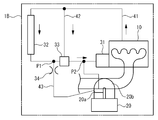
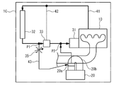
- FIG. 1 is a schematic configuration diagram of a cooling system 1A.
- the cooling system 1 ⁇ / b> A includes an internal combustion engine 10, a Stirling engine 20, a pump 31, a radiator 32, and a thermostat 33.
- a main passage portion 41, a bypass passage portion 42, and a branch passage portion 43 are provided.
- These passage portions 41, 42, and 43 are pipes, and form passages through which cooling water that is a cooling medium flows.
- the arrows along the passage portions 41, 42, and 43 indicate the flow direction of the cooling water.
- the internal combustion engine 10 is a water-cooled internal combustion engine and circulates cooling water.
- the pump 31 pumps the cooling water.
- the radiator 32 exchanges heat between the circulating cooling water and the air to cool the cooling water.
- the thermostat 33 adjusts the temperature of the cooling water flowing through the internal combustion engine 10.
- the thermostat 33 is a mechanical valve that operates according to the temperature of the cooling water.
- the internal combustion engine 10, the pump 31, the radiator 32, and the thermostat 33 are provided so as to be interposed in the main passage portion 41.
- the main passage portion 41 forms a circulation path in which the cooling water pumped by the pump 31 is circulated in the order of the internal combustion engine 10, the radiator 32, and the thermostat 33 and then returned to the pump 31.
- the pump 31 pumps the cooling water to the internal combustion engine 10. Further, the radiator 32 cools the cooling water flowing through the internal combustion engine 10. The main passage portion 41 causes the coolant to flow from the radiator 32 to the internal combustion engine 10 via the pump 31.
- the pump 31 is provided in the internal combustion engine 10 and is a mechanical pump that is driven by the power of the internal combustion engine 10. The pump 31 may be an electric pump.
- the bypass passage portion 42 is provided with respect to the main passage portion 41.
- the bypass passage portion 42 forms a path that bypasses the radiator 32. For this reason, the bypass passage 42 bypasses the radiator 32 and causes the cooling water flowing through the internal combustion engine 10 to flow.
- the thermostat 33 is provided at the junction of the main passage portion 41 and the bypass passage portion 42. Specifically, the thermostat 33 adjusts the flow rate of the cooling water between when the cooling water is circulated through the radiator 32 and when the cooling water is circulated through the bypass passage 42. It is a thermostat with a bypass valve that can adjust the temperature of the cooling water to be circulated.
- the thermostat 33 is a radiator after the cold start of the internal combustion engine 10 until the warm-up is completed, that is, until the cooling water temperature reaches an appropriate temperature (for example, 80 ° C.). It operates so that the cooling water does not flow through 32. Further, after the warm-up is completed, the ratio of the flow rate of the cooling water to be circulated to the radiator 32 is increased as the temperature of the cooling water circulated to the internal combustion engine 10 becomes higher (for example, when the load of the internal combustion engine 10 is higher). Operates on. The thermostat 33 may operate so that a small amount of cooling water flows through the radiator 32 until the warm-up is completed after the cold start of the internal combustion engine 10.
- the branch passage portion 43 is provided with respect to the main passage portion 41.
- the branch passage portion 43 is provided with the Stirling engine 20 interposed therebetween.
- the cross-sectional area of the passage formed by the branch passage portion 43 is set smaller than the cross-sectional area of the passage formed by the main passage portion 41.
- the diameter of the passage formed by the branch passage portion 43 is set smaller than the diameter of the passage formed by the main passage portion 41.
- the branch passage portion 43 branches from the main passage portion 41 at the first connection point P1, and is connected to the downstream portion of the main passage portion 41 with respect to the first connection point P1 via the Stirling engine 20. 2 join points P2.
- the branch passage 43 is branched at the first connection point P1, so that the cooling water cooled by the radiator 32 flows directly.
- connection points P1 and P2 are provided in a portion of the main passage portion 41 between the radiator 32 and the pump 31.
- the thermostat 33 is provided so as to be interposed in the portion of the main passage portion 41 between the connection points P1 and P2.
- the thermostat 33 provided in this way corresponds to a resistance portion that acts as a flow resistance of the cooling water flowing through the main passage portion 41.
- the Stirling engine 20 includes a cooler 20a and a heater 20b.
- the Stirling engine 20 distributes cooling water. Specifically, the cooling water is circulated through the cooler 20a.
- the cooler 20a exchanges heat between the cooling water and the working fluid to cool the working fluid.
- the heater 20b exchanges heat between the working fluid and the exhaust gas of the internal combustion engine 10 to heat the working fluid.
- the cooling water constitutes a low temperature heat source of the Stirling engine 20
- the exhaust gas constitutes a high temperature heat source of the Stirling engine 20.
- the temperature difference of a low temperature heat source and a high temperature heat source can be expanded, so that the temperature of the cooling water which distribute
- connection points P ⁇ b> 1 and P ⁇ b> 2 are provided in a portion of the main passage portion 41 between the radiator 32 and the pump 31. Further, a thermostat 33 acting as a flow resistance is provided so as to be interposed in the portion between the connection points P1 and P2 in the main passage portion 41. Further, the branch passage portion 43 is branched at the first connection point P1.
- the cooling system 1A can generate a pressure difference between the connection points P1 and P2 only by operating the pump 31. Thereby, the cooling water can be circulated through the branch passage portion 43. Further, the cooling system 1A can cause the Stirling engine 20 to circulate the cooling water having the lowest temperature among the cooling water that circulates through the cooling system 1A. For this reason, the cooling system 1 ⁇ / b> A can appropriately distribute cooling water common to the internal combustion engine 10 and the Stirling engine 20 in that effective cooling of the Stirling engine 20 can be ensured.
- the cooling system 1A uses a thermostat 33, which is generally used for adjusting the temperature of cooling water flowing through the internal combustion engine 10, as a resistance portion. For this reason, the cooling system 1 ⁇ / b> A can appropriately distribute the cooling water in that it can be configured to be advantageous in terms of cost.
- the thermostat 33 adjusts the ratio of the flow rate of the cooling water between the case where the cooling water is circulated through the radiator 32 and the case where the cooling water which is circulated through the radiator 32 is bypassed. In this respect, the thermostat 33 prevents the cooling water from flowing through the radiator 32 until the warm-up of the internal combustion engine 10 is completed.
- the cooling system 1 ⁇ / b> A can also distribute the cooling water suitably in that the warming-up of the internal combustion engine 10 can be promoted while ensuring effective cooling of the Stirling engine 20.
- the ratio of the flow rate of the cooling water to be circulated to the radiator 32 is increased as the temperature of the cooling water circulated to the internal combustion engine 10 after the thermostat 33 is warmed up.
- the thermostat 33 acts as a relatively small flow resistance.
- the cooling system 1A can appropriately cool the internal combustion engine 10 when it is highly necessary to cool the internal combustion engine 10.
- the Stirling engine 20 can be cooled with the remaining power. Therefore, the cooling system 1A can be suitably distributed in that the Stirling engine 20 can be cooled while securing the cooling of the internal combustion engine 10 when the necessity of cooling the internal combustion engine 10 is high.
- the cooling system 1A the cross-sectional area of the passage formed by the branch passage portion 43 is set smaller than the cross-sectional area of the passage formed by the main passage portion 41. Therefore, the cooling system 1 ⁇ / b> A can preferentially distribute the cooling water to the internal combustion engine 10 when distributing the common cooling water to the internal combustion engine 10 and the Stirling engine 20. As a result, when it is highly necessary to cool the internal combustion engine 10, the cooling water can be suitably distributed from the viewpoint that the cooling of the internal combustion engine 10 can be ensured.
- the thermostat 33 may be an electronic control valve. In this case, for example, based on the cooling water temperature and the load of the internal combustion engine 10, the same operation and effect can be achieved by further providing an electronic control device that controls the operation of the thermostat 33 as described above. The same applies to the following embodiments.
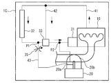
- FIG. 2 is a schematic configuration diagram of the cooling system 1B.
- the cooling system 1B is substantially the same as the cooling system 1A, except that it further includes a throttle valve 34.
- the throttle valve 34 is provided so as to be interposed in the branch passage portion 43.
- the throttle valve 34 is provided so as to be interposed in a portion of the branch passage portion 43 upstream of the Stirling engine 20.
- the throttle valve 34 squeezes the flow rate of the cooling water flowing, thereby reducing the flow rate of the cooling water flowing through the branch passage portion 43 as compared with the case where the throttle valve 34 is not provided.
- the internal combustion engine 10 when the load on the internal combustion engine 10 is small after completion of warm-up, the internal combustion engine 10 is appropriately cooled as follows by causing the thermostat 33 to act as a relatively large flow resistance. Can be considered. That is, the ratio of the flow rate of the cooling water flowing through the radiator 32 is made relatively small, whereby the cooling water flowing through the radiator 32 and the cooling water flowing through the bypass passage portion 42 are mixed to produce an internal combustion engine. It can be considered that the internal combustion engine 10 is appropriately cooled by supplying it to the engine 10.
- the cooling system 1B reduces the flow rate of the cooling water flowing through the branch passage portion 43 by the throttle valve. As a result, even when the thermostat 33 acts as a relatively large flow resistance, the internal combustion engine 10 can be prevented from being overcooled. Therefore, the cooling system 1B cools the internal combustion engine 10 and the Stirling engine 20 in that the internal combustion engine 10 can be appropriately cooled when the thermostat 33 acts as a relatively large flow resistance compared to the cooling system 1A. Water can be circulated suitably.
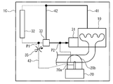
- FIG. 3 is a schematic configuration diagram of the cooling system 1C.
- the cooling system 1 ⁇ / b> C is substantially the same as the cooling system 1 ⁇ / b> B except that a variable throttle valve 35 is provided instead of the throttle valve 34.
- the variable throttle valve 35 is provided in the branch passage portion 43 in the same manner as the throttle valve 34.
- the variable throttle valve 35 changes the degree of throttle of the flow rate of the circulating cooling water.
- the variable throttle valve 35 is a mechanical valve that operates according to the pressure of the cooling water.
- the variable throttle valve 35 may be a mechanical valve that operates according to the temperature of the cooling water.
- variable throttle valve 35 operates so as to change the throttle degree of the flow rate of the circulating cooling water by opening the valve with a greater degree as the thermostat 33 acts as a relatively small flow resistance.
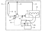
- FIG. 4 is a diagram showing a first circulation mode of the cooling water.
- FIG. 5 is a diagram showing a second flow mode of the cooling water.
- FIG. 6 is a diagram showing a third flow mode of the cooling water.
- FIG. 4 shows a flow mode when the engine is cold
- FIG. 5 shows a flow mode when the load of the internal combustion engine 10 is a light and medium load
- FIG. 6 shows a flow mode when the load of the internal combustion engine 10 is a high load.
- 4, 5, and 6, arrows that are superimposed on the main passage portion 41, the bypass passage portion 42, or the branch passage portion 43 indicate the circulation mode of the cooling water.
- the thickness of the arrow indicates the magnitude of the flow rate.
- the main passage portion 41, the bypass passage portion 42, or the branch passage portion 43 indicated by a broken line indicates a state where the cooling water is not circulating.
- the cooling water discharged from the pump 31 flows through the main passage 41 after flowing through the internal combustion engine 10. And all the cooling water which distribute
- the cooling water that has flowed into the bypass passage portion 42 flows again into the main passage portion 41 via the thermostat 33 and returns to the pump 31. Accordingly, at this time, the cooling water does not flow through the radiator 32. At the same time, the cooling water does not flow through the branch passage portion 43 and the Stirling engine 20. At this time, as described above, a small amount of cooling water may be circulated through the radiator 32.
- the coolant discharged from the pump 31 flows through the main passage portion 41 after flowing through the internal combustion engine 10.
- a part of the cooling water flowing through the main passage portion 41 is diverted to the bypass passage portion 42 on the way.
- the cooling water that has flowed into the bypass passage portion 42 flows again into the main passage portion 41 via the thermostat 33 and returns to the pump 31.
- the cooling water that has not been split flows through the radiator 32. Thereafter, a part of the cooling water is diverted to the branch passage portion 43.
- the cooling water that has not been diverted to the branch passage portion 43 returns to the pump 31 via the thermostat 33.
- the cooling water divided into the branch passage portion 43 flows through the variable throttle valve 35 and the Stirling engine 20, then flows into the main passage portion 41 again, and returns to the pump 31. At this time, the variable throttle valve 35 is opened to a relatively small degree so that the cooling water is not circulated through the Stirling engine 20 more than necessary.
- the cooling water discharged from the pump 31 flows through the internal combustion engine 10 and then passes through the main passage portion 41. Circulate. Then, all the cooling water flows into the radiator 32 without being diverted to the bypass passage portion 42. After flowing through the radiator 32, the cooling water is diverted to the branch passage portion 43 and returns to the pump 31 via the thermostat 33 or the branch passage portion 43. At this time, the variable throttle valve 35 is opened with a relatively large degree (for example, fully open).
- the thermostat 33 and the variable throttle valve 35 are flow rates that can change the ratio between the flow rate of the cooling water flowing through the internal combustion engine 10 and the flow rate of the cooling water flowing through the Stirling engine 20 according to the operating state of the internal combustion engine 10. Corresponds to the ratio change part.
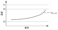
- FIG. 7 is a diagram showing the relationship between the cooling water temperature Ts_in at the inlet of the Stirling engine 20 and the load of the internal combustion engine 10.
- temperature T1 indicates the coolant temperature at the inlet of the radiator 32
- temperature T2 indicates the coolant temperature at the inlet of the internal combustion engine 10
- temperature T3 indicates the outside air temperature.
- the temperature T1 is, for example, 100 ° C.
- the temperature T2 is, for example, 80 ° C.
- the temperature T3 is, for example, 40 ° C.
- the thermostat 33 diverts a part of the cooling water to the bypass passage 42, thereby reducing the flow rate of the cooling water flowing through the radiator 32. .
- the variable throttle valve 35 opens with a relatively small degree.
- the cooling system 1C can cool the cooling water so as to have a large remaining capacity for cooling the internal combustion engine 10. Further, the cooling water cooled by the radiator 32 can be distributed to the internal combustion engine 10 and the Stirling engine 20.
- the cooling water cooled by the radiator 32 and the cooling water bypassed by the radiator 32 are mixed and circulated through the internal combustion engine 10, whereby the temperature T2 can be set to an appropriate temperature.
- the temperature Ts_in can be significantly reduced compared with the temperature T2 by circulating the cooling water cooled so as to have a large margin for cooling the internal combustion engine 10 to the Stirling engine 20.
- the thermostat 33 distributes all the cooling water to the radiator 32. At this time, even if the thermostat 33 acts as a relatively small flow resistance, the variable throttle valve 35 opens with a relatively large degree.
- the cooling system 1C preferentially distributes the cooling water cooled by the radiator 32 to the internal combustion engine 10, while the load of the internal combustion engine 10 is light and medium. Cooling water can also be circulated through the Stirling engine 20 at a larger flow rate than in some cases. Thus, the Stirling engine 20 can be cooled while giving priority to the cooling of the internal combustion engine 10.
- the cooling system 1C can more appropriately distribute the cooling water to the internal combustion engine 10 and the Stirling engine 20 in accordance with the operating state of the internal combustion engine 10, and is more preferably compared with the cooling system 1B. Can be distributed.
- the variable throttle valve 35 may be an electronic control valve.
- the electronic control device that controls the operation of the variable throttle valve 35 as described above is further provided, and the same operational effects can be obtained. it can.
- the resistance portion may be a variable throttle valve. Even in this case, effective cooling of the Stirling engine can be secured. Further, when the temperature of the cooling medium to be circulated through the internal combustion engine becomes higher, the degree of throttling is changed so that the flow rate of the circulating cooling medium becomes larger, so that the internal combustion engine has a higher need for cooling the internal combustion engine.
- the Stirling engine can be cooled while ensuring the cooling of the engine.
Landscapes
- Engineering & Computer Science (AREA)
- Chemical & Material Sciences (AREA)
- Combustion & Propulsion (AREA)
- Mechanical Engineering (AREA)
- General Engineering & Computer Science (AREA)
- Engine Equipment That Uses Special Cycles (AREA)
- Temperature-Responsive Valves (AREA)
- Devices That Are Associated With Refrigeration Equipment (AREA)
- Other Air-Conditioning Systems (AREA)
Abstract
Description
ポンプ 31
ラジエータ 32
サーモスタット 33
主通路部 41
バイパス通路部 42
分岐通路部 43
Claims (5)
- 冷却媒体を流通させる内燃機関と、
前記内燃機関に冷却媒体を圧送するポンプと、
前記内燃機関を流通した冷却媒体を冷却するラジエータと、
前記ラジエ-タから前記ポンプを介して前記内燃機関に冷却媒体を流通させる主通路部と、
冷却媒体を流通させるスターリングエンジンと、
前記主通路部から第1の接続地点で分岐するとともに、前記スターリングエンジンを介して、前記主通路部のうち、前記第1の接続地点よりも下流側の部分に第2の接続地点で合流する分岐通路部と、
前記主通路部を流通する冷却媒体の流通抵抗として作用する抵抗部と、を備え、
前記主通路部のうち、前記ラジエータと前記ポンプとの間の部分に前記第1の接続地点と前記第2の接続地点とを設けるとともに、前記主通路部のうち、前記第1の接続地点と前記第2の接続地点との間の部分に、前記抵抗部を介在させるようにして設けている冷却システム。 - 請求項1記載の冷却システムであって、
前記ラジエータをバイパスさせるようにして、前記内燃機関を流通した冷却媒体を流通させるバイパス通路部をさらに備え、
前記抵抗部が、前記ラジエータに冷却媒体を流通させる場合と、前記バイパス通路部に冷却媒体を流通させる場合との間で、冷却媒体の流量の割合を調節することで、前記内燃機関に流通させる冷却媒体の温度を調節可能なバイパス弁付きサーモスタットである冷却システム。 - 請求項1記載の冷却システムであって、
前記抵抗部が、流通する冷却媒体の流量の絞り度合いを変更可能な可変絞り弁である冷却システム。 - 請求項1から3いずれか1項記載の冷却システムであって、
前記分岐通路部が形成する通路の断面積が、前記主通路部が形成する通路の断面積よりも小さく設定されている冷却システム。 - 請求項1から4いずれか1項記載の冷却システムであって、
前記抵抗部を含み、前記内燃機関の運転状態に応じて、前記内燃機関に流通させる冷却媒体の流量と、前記スターリングエンジンに流通させる冷却媒体の流量との割合を変更可能な流量割合変更部をさらに備える冷却システム。
Priority Applications (5)
| Application Number | Priority Date | Filing Date | Title |
|---|---|---|---|
| JP2012536626A JP5333679B2 (ja) | 2011-02-10 | 2011-02-10 | 冷却システム |
| PCT/JP2011/052854 WO2012108030A1 (ja) | 2011-02-10 | 2011-02-10 | 冷却システム |
| DE112011104871.8T DE112011104871B4 (de) | 2011-02-10 | 2011-02-10 | Kühlsystem |
| CN201180032080.3A CN102971518B (zh) | 2011-02-10 | 2011-02-10 | 冷却系统 |
| US13/581,492 US8978597B2 (en) | 2011-02-10 | 2011-02-10 | Cooling system |
Applications Claiming Priority (1)
| Application Number | Priority Date | Filing Date | Title |
|---|---|---|---|
| PCT/JP2011/052854 WO2012108030A1 (ja) | 2011-02-10 | 2011-02-10 | 冷却システム |
Publications (1)
| Publication Number | Publication Date |
|---|---|
| WO2012108030A1 true WO2012108030A1 (ja) | 2012-08-16 |
Family
ID=46638273
Family Applications (1)
| Application Number | Title | Priority Date | Filing Date |
|---|---|---|---|
| PCT/JP2011/052854 Ceased WO2012108030A1 (ja) | 2011-02-10 | 2011-02-10 | 冷却システム |
Country Status (5)
| Country | Link |
|---|---|
| US (1) | US8978597B2 (ja) |
| JP (1) | JP5333679B2 (ja) |
| CN (1) | CN102971518B (ja) |
| DE (1) | DE112011104871B4 (ja) |
| WO (1) | WO2012108030A1 (ja) |
Families Citing this family (3)
| Publication number | Priority date | Publication date | Assignee | Title |
|---|---|---|---|---|
| DE102014207978B4 (de) * | 2014-04-28 | 2018-12-20 | Mahle International Gmbh | Kühlkreislauf zur Temperierung mehrerer Wärmequellen mit mehreren Thermostaten |
| DE102016222797A1 (de) * | 2016-11-18 | 2018-05-24 | Robert Bosch Gmbh | Kryopumpe |
| US10781771B1 (en) * | 2019-09-22 | 2020-09-22 | Ghasem Kahe | Automatic cooling system for combustion engine |
Citations (2)
| Publication number | Priority date | Publication date | Assignee | Title |
|---|---|---|---|---|
| JP2005090376A (ja) * | 2003-09-18 | 2005-04-07 | Honda Motor Co Ltd | 内燃機関とスターリング機関とを備える動力装置 |
| JP2008051062A (ja) * | 2006-08-28 | 2008-03-06 | Hitachi Ltd | 自動車 |
Family Cites Families (11)
| Publication number | Priority date | Publication date | Assignee | Title |
|---|---|---|---|---|
| US4057040A (en) * | 1976-04-12 | 1977-11-08 | Wax Archie E | Internal combustion engine system |
| JP2000073763A (ja) | 1998-08-26 | 2000-03-07 | Nissan Motor Co Ltd | ハイブリッド車用冷却装置 |
| RU2162533C1 (ru) * | 1999-09-30 | 2001-01-27 | Военный инженерно-космический университет им. А.Ф. Можайского | Автономная теплоэнергетическая система для одновременного производства электроэнергии и тепла |
| JP4192811B2 (ja) | 2004-03-08 | 2008-12-10 | トヨタ自動車株式会社 | 複数エンジンの冷却装置 |
| DE102004045540A1 (de) * | 2004-09-21 | 2006-03-23 | Robert Bosch Gmbh | Verfahren und Vorrichtung zum Betreiben einer Brennkraftmaschine mit einem Katalysator |
| FR2881127B1 (fr) | 2005-01-24 | 2007-05-04 | Guy Morin | Etrier d'equitation 3d a assistance de pied amortissant, ergonomique, antiblocage, adaptable au poids du cavalier |
| JP4631652B2 (ja) | 2005-10-25 | 2011-02-16 | トヨタ自動車株式会社 | 冷却システムおよびその制御方法並びに自動車 |
| JP2007240035A (ja) * | 2006-03-06 | 2007-09-20 | Tokyo Electron Ltd | 冷却加熱装置及び載置装置 |
| GB2437309B (en) * | 2006-04-22 | 2011-09-14 | Ford Global Tech Llc | A cooling system for an engine |
| CN201002715Y (zh) * | 2006-12-14 | 2008-01-09 | 上海交通大学 | 大型船舶高速航行的燃气轮机斯特林发动机电力推进装置 |
| FR2915771B1 (fr) * | 2007-05-03 | 2014-01-03 | Renault Sas | Ensemble de refroidissement d'un moteur a combustion interne |
-
2011
- 2011-02-10 CN CN201180032080.3A patent/CN102971518B/zh not_active Expired - Fee Related
- 2011-02-10 US US13/581,492 patent/US8978597B2/en active Active
- 2011-02-10 WO PCT/JP2011/052854 patent/WO2012108030A1/ja not_active Ceased
- 2011-02-10 DE DE112011104871.8T patent/DE112011104871B4/de not_active Expired - Fee Related
- 2011-02-10 JP JP2012536626A patent/JP5333679B2/ja not_active Expired - Fee Related
Patent Citations (2)
| Publication number | Priority date | Publication date | Assignee | Title |
|---|---|---|---|---|
| JP2005090376A (ja) * | 2003-09-18 | 2005-04-07 | Honda Motor Co Ltd | 内燃機関とスターリング機関とを備える動力装置 |
| JP2008051062A (ja) * | 2006-08-28 | 2008-03-06 | Hitachi Ltd | 自動車 |
Also Published As
| Publication number | Publication date |
|---|---|
| US20130306004A1 (en) | 2013-11-21 |
| JPWO2012108030A1 (ja) | 2014-07-03 |
| JP5333679B2 (ja) | 2013-11-06 |
| DE112011104871T5 (de) | 2013-12-24 |
| US8978597B2 (en) | 2015-03-17 |
| DE112011104871B4 (de) | 2016-08-25 |
| CN102971518B (zh) | 2015-07-08 |
| CN102971518A (zh) | 2013-03-13 |
Similar Documents
| Publication | Publication Date | Title |
|---|---|---|
| US8739745B2 (en) | Cooling system and method | |
| US7594483B2 (en) | Internal combustion engine cooling system | |
| JP6269825B2 (ja) | 内燃機関の冷却回路 | |
| RU2589556C2 (ru) | Система двигателя и способ снижения стоимости ее производства | |
| US10718256B2 (en) | Powertrain thermal management system and method | |
| CN205477882U (zh) | 冷却循环装置 | |
| JP2007519853A (ja) | 排気および給気を冷却するための装置 | |
| CN102197205A (zh) | 用于独立于其它消耗件对发动机进行热调节的冷却回路 | |
| JP5585723B2 (ja) | スターリングエンジンの出力制御装置 | |
| JP5333679B2 (ja) | 冷却システム | |
| JP2016050545A (ja) | 車両の冷却システム | |
| JP2010209736A (ja) | エンジンの暖機制御装置 | |
| CN107532500B (zh) | 用于液冷变速器的冷却剂回路 | |
| JP5668318B2 (ja) | 車両の冷却装置 | |
| JP6131937B2 (ja) | ロータリピストンエンジンの冷却装置 | |
| JP2008133772A (ja) | エンジンの冷却装置 | |
| JP6604540B2 (ja) | エンジン冷却装置 | |
| JP2018053720A (ja) | 内燃機関の冷却システム | |
| CN111206980B (zh) | 发动机水套和具有该发动机水套的发动机冷却系统 | |
| JP2001271644A (ja) | エンジンのオイル温度調節方法及びオイル温度調節装置 | |
| JP7460029B2 (ja) | 車両の冷却装置 | |
| JP2013124546A (ja) | 車両の冷却装置 | |
| JP6107798B2 (ja) | ロータリピストンエンジンの冷却装置 | |
| WO2015049833A1 (ja) | 吸気冷却装置 | |
| JP2016008588A (ja) | 車両用内燃機関の冷却装置 |
Legal Events
| Date | Code | Title | Description |
|---|---|---|---|
| WWE | Wipo information: entry into national phase |
Ref document number: 201180032080.3 Country of ref document: CN |
|
| WWE | Wipo information: entry into national phase |
Ref document number: 2012536626 Country of ref document: JP |
|
| WWE | Wipo information: entry into national phase |
Ref document number: 13581492 Country of ref document: US |
|
| 121 | Ep: the epo has been informed by wipo that ep was designated in this application |
Ref document number: 11858193 Country of ref document: EP Kind code of ref document: A1 |
|
| WWE | Wipo information: entry into national phase |
Ref document number: 112011104871 Country of ref document: DE Ref document number: 1120111048718 Country of ref document: DE |
|
| 122 | Ep: pct application non-entry in european phase |
Ref document number: 11858193 Country of ref document: EP Kind code of ref document: A1 |