WO2012108018A1 - 液晶プロジェクタ - Google Patents
液晶プロジェクタ Download PDFInfo
- Publication number
- WO2012108018A1 WO2012108018A1 PCT/JP2011/052784 JP2011052784W WO2012108018A1 WO 2012108018 A1 WO2012108018 A1 WO 2012108018A1 JP 2011052784 W JP2011052784 W JP 2011052784W WO 2012108018 A1 WO2012108018 A1 WO 2012108018A1
- Authority
- WO
- WIPO (PCT)
- Prior art keywords
- liquid crystal
- crystal panel
- crystal projector
- bracket
- projection lens
- Prior art date
- Legal status (The legal status is an assumption and is not a legal conclusion. Google has not performed a legal analysis and makes no representation as to the accuracy of the status listed.)
- Ceased
Links
Images





Classifications
-
- G—PHYSICS
- G03—PHOTOGRAPHY; CINEMATOGRAPHY; ANALOGOUS TECHNIQUES USING WAVES OTHER THAN OPTICAL WAVES; ELECTROGRAPHY; HOLOGRAPHY
- G03B—APPARATUS OR ARRANGEMENTS FOR TAKING PHOTOGRAPHS OR FOR PROJECTING OR VIEWING THEM; APPARATUS OR ARRANGEMENTS EMPLOYING ANALOGOUS TECHNIQUES USING WAVES OTHER THAN OPTICAL WAVES; ACCESSORIES THEREFOR
- G03B21/00—Projectors or projection-type viewers; Accessories therefor
- G03B21/14—Details
- G03B21/145—Housing details, e.g. position adjustments thereof
-
- H—ELECTRICITY
- H04—ELECTRIC COMMUNICATION TECHNIQUE
- H04N—PICTORIAL COMMUNICATION, e.g. TELEVISION
- H04N9/00—Details of colour television systems
- H04N9/12—Picture reproducers
- H04N9/31—Projection devices for colour picture display, e.g. using electronic spatial light modulators [ESLM]
- H04N9/3141—Constructional details thereof
-
- G—PHYSICS
- G03—PHOTOGRAPHY; CINEMATOGRAPHY; ANALOGOUS TECHNIQUES USING WAVES OTHER THAN OPTICAL WAVES; ELECTROGRAPHY; HOLOGRAPHY
- G03B—APPARATUS OR ARRANGEMENTS FOR TAKING PHOTOGRAPHS OR FOR PROJECTING OR VIEWING THEM; APPARATUS OR ARRANGEMENTS EMPLOYING ANALOGOUS TECHNIQUES USING WAVES OTHER THAN OPTICAL WAVES; ACCESSORIES THEREFOR
- G03B33/00—Colour photography, other than mere exposure or projection of a colour film
- G03B33/10—Simultaneous recording or projection
- G03B33/12—Simultaneous recording or projection using beam-splitting or beam-combining systems, e.g. dichroic mirrors
Definitions
- the present invention relates to a liquid crystal projector.
- Patent Document 1 discloses a technology in which a change in focal length of a projection lens due to a temperature change in a projector is offset by an expansion or contraction according to a temperature characteristic of the expansion / contraction member.
- an engine bottom In the liquid crystal projector, other main components are attached and positioned to a base called an engine bottom.
- a material of the engine bottom for example, unsaturated polyester resin is used.
- the use of metal die cast having a low coefficient of thermal expansion by materials such as iron and aluminum can greatly improve the expansion and contraction due to temperature change of the engine bottom and can solve the above-mentioned problem of defocusing.
- metal die casting is expensive compared to resin and sheet metal, and there is a problem in mass productivity, which is not preferable.
- Patent Document 1 is a document relating to a method for solving the problems when using an engine bottom made of resin, and it seems that a temperature compensation effect can be expected.
- the structure is complicated, and if tolerances of dimensions of components to be used are accumulated, there is also a possibility that the temperature compensation effect may vary.
- An object of the present invention is to provide a liquid crystal projector in which defocusing caused by temperature change is reduced.
- the present invention is a liquid crystal projector which projects and displays an image optically.
- a liquid crystal panel for generating an image to be projected and displayed, a projection lens for projecting an image generated by the liquid crystal panel to the outside, and a component for fixing the liquid crystal projector including the projection lens and the liquid crystal panel An engine bottom made of a resin material, a first mounting member for fixing the liquid crystal panel to the engine bottom, a second mounting member for fixing the projection lens to the engine bottom, and A position of the projection lens as viewed from the optical axis is located near the first mounting member, and a position as viewed from the optical axis of the projection lens is located near the second attachment member It is particularly preferable to have a fourth mounting member and a metal expansion and contraction preventing member fixed to the engine bottom by the third and fourth mounting members. It is set to.
- the present invention it is possible to provide a liquid crystal projector in which the focus shift due to a temperature change is reduced, and it is possible to contribute to the improvement of the basic performance of the liquid crystal projector.
- the block diagram of the optical engine of a liquid crystal projector The sketch of the projection lens vicinity of a liquid crystal projector. An exploded view around the cross prism.
- the 3rd external view of the optical engine of a liquid crystal projector. A plan view around the brequette.
- the 1st external view which shows the attachment method of a bracket.
- the 2nd external view which shows the attachment method of a bracket.
- the 3rd external view which shows the attachment method of a bracket.
- the 4th external view which shows the attachment method of a bracket.
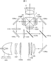
- FIG. 1 shows a block diagram of an optical engine of a liquid crystal projector.
- the light source unit 101 includes a tube 101a which is a light emitting portion and a reflector 101b which is a reflecting surface.
- the luminous flux emitted from the tube 101a disposed at the first focal position of the elliptical shaped reflector 101b is reflected from the reflecting surface so as to be condensed at the second focal position of the reflector 101b.
- the condensed luminous flux whose luminous flux size is reduced is converted into a collimated luminous flux by the concave lens 102 having a collimating action.
- the concave lens 102 for performing the parallelizing operation is not necessary.
- the parallel light beams emitted from the concave lens 102 are divided into partial light beams by the respective cell lenses of the first multi lens array 103 a and condensed on the respective cell lenses of the second multi lens array 103 b corresponding to the first multi lens.
- Ru The collected partial light fluxes are temporarily separated into two linearly polarized lights whose vibration directions are orthogonal to each other by the linear polarization unit 104, and the vibration direction of one linearly polarized light is matched with the other vibration direction. The vibration direction is converted to linear polarization in one direction.
- the partial light fluxes emitted from the linear polarization unit 104 are superimposed and irradiated onto the liquid crystal panel units 1R, 1G, and 1B for each color of RGB by the superimposing lens 105.
- reflection mirrors 106a, 106b, 106c, 106d for bending the light path and dichroic mirrors 107a and 107b as color separation optical units are provided.
- collimator lenses 108R, 108G, 108B for collimating the principal ray of the projected light beam are disposed in front of the liquid crystal panel units 1R, 1G, 1B.
- relay lenses 109 and 110 for mapping the superimposed light flux on the position of the liquid crystal panel unit 1R for red are disposed.
- the luminous flux from the tube 101a supplied to the liquid crystal panel units 1R, 1G, 1B is an image R signal, an image G signal, an image B signal separately supplied to each of the liquid crystal panel units 1R, 1G, 1B.
- the amount of light that can pass through the liquid crystal panel is changed according to the level of.
- the information of the video signal is given to the luminous flux.
- the liquid crystal panel units 1R, 1G, and 1B are provided not only with the liquid crystal panels but also with polarizing plates for passing light beams in a predetermined vibration direction.
- the respective light beams having passed through the liquid crystal panel units 1R, 1G, 1B are combined with each other by the cross prism 2, and an image according to the video signal is displayed on a screen (not shown) provided outside via the projection lens 3. Do.
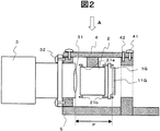
- FIG. 2 is a sketch of the vicinity of the projection lens 3 of the liquid crystal projector.
- the liquid crystal panel unit 1 (only the convenience 1G shown is shown), the cross prism 2, the projection lens 3 and the periphery thereof are viewed from the side surface on the left side with respect to the block diagram of FIG.
- the engine bottom 5 (the upper right to lower left diagonal lines in the figure) which is the base of the liquid crystal projector, but depending on the components, the engine bottom 5 may be attached through other components. It is attached.
- the projection lens 3 is attached and fixed to the engine bottom 5 using a fixing member 32 such as a screw.
- the cross prism 2 is fixed to the prism holder 4 (hatched in the direction from the upper left to the lower right in the drawing).
- the prism holder 4 is first positioned on the engine bottom 5 by the reference pin 42 and then fixed using a fixing member 41 such as a screw. That is, the cross prism 2 is attached and fixed to the engine bottom 5 via the prism holder 4.
- the liquid crystal panel unit 1 including the liquid crystal panel 11 has a mounting hole, and the panel bracket 21 (21a, 21b) of the cross prism 2 is inserted and fixed to the cross prism 2 by being inserted. That is, the liquid crystal panel unit 1 is attached and fixed to the engine bottom 5 via the panel bracket 21, the cross prism 2, and the prism holder 4.
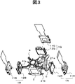
- FIG. 3 is an exploded view of the periphery of the cross prism 2 and is a drawing drawn from the diagonally upper left direction of FIG.
- the liquid crystal panel unit 1 includes a liquid crystal panel 11 and a polarizing plate 12.
- the cross prism 2 is fixed to the prism holder 4.
- the panel brackets 21 a and 21 b provided on the upper and lower sides of the cross prism 2 are inserted into mounting holes (four places per liquid crystal panel in FIG. 3) around the liquid crystal panel 11 to fix the liquid crystal panel unit 1 to the cross prism 2.
- an attachment hole 41 a for passing a fixing member 41 (not shown) such as a screw is provided, and the fixing member 41 passes through the attachment hole 41 a.
- Fix to Although only one attachment hole 41a is given a code in FIG. 3, it is preferable to provide about three attachment holes around the prism holder 4 as described above.
- a member extending upward from the liquid crystal panel 11 is a flexible substrate for supplying a video signal to the liquid crystal panel 11.
- the panel brackets 21a and 21b are provided with a total of 12 convex portions because there are three liquid crystal panel units 1, there are a total of six panel brackets 21a and 21b because they are behind other components in FIG. It is drawn. In order to avoid the complication of the drawings, only some of them are given reference numerals. Also, although the bracket 6 will be described in detail later, an example of the shape and a schematic position are shown here.
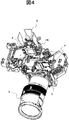
- FIG. 4 is a first external view of the optical engine of the liquid crystal projector, and is drawn from the same direction as FIG.
- the cross prism 2 having the liquid crystal panel unit 1 attached to the periphery is in a state of being removed upward.
- FIG. 5 is a second external view of the optical engine of the liquid crystal projector, and is drawn from the same direction as FIG.
- the cross prism 2 having the liquid crystal panel unit 1 attached to the periphery is attached to the engine bottom 5 at a predetermined attachment position. For this reason, the prism holder 4 above the cross prism 2 is mainly drawn.
- the shift of the focus due to the temperature change is caused by the change of the distance between the liquid crystal panel unit 1 and the projection lens 3 depending on the temperature. If this distance is defined more specifically, the distance P between the display surface of the liquid crystal panel 11 in FIG. 2 and the rear spherical lens 31 included in the projection lens 3 is obtained. As can be seen from FIG. 2, the distance P between the liquid crystal panel 11 and the projection lens 3 may change mainly due to the expansion and contraction of the panel bracket 21, the prism holder 4, and the engine bottom 5.
- the relative position between the cross prism 2 and the liquid crystal panel unit 1 is defined by a panel bracket 21. Since the panel bracket has a small volume of parts and, for example, an iron material can be used, expansion and contraction with respect to temperature change hardly cause problems.
- the prism holder 4 and the engine bottom 5 have problems in cost and mass productivity if metal materials are used, and there is also a problem that the weight increases. For this reason, for example, resins containing polyphenyl ether and polystyrene and unsaturated polyesters are often used. When using a resin, expansion and contraction due to temperature change become a problem. In particular, expansion and contraction of the engine bottom 5 having a large size changes the distance P between the liquid crystal panel unit 1 and the projection lens 3 to be a major factor causing defocusing during use.
- FIG. 6 is a first external view of the optical engine of the liquid crystal projector, including the mounting method of the bracket 6 also shown in FIGS. 4 and 5 above. As will be described later, the shape of the bracket 6 is somewhat different from that shown in FIGS. 4 and 5.
- One feature of the present embodiment is to reduce the change in the distance between the liquid crystal panel unit 1 and the projection lens 3 by using, for example, a bracket 6 made of stainless steel.
- the engine upper case 7 is a case mounted on the upper side of the engine bottom 5 and is made of, for example, polycarbonate resin.
- the bracket 6 is attached to the engine bottom 5 by attachment members 61 and 62 including, for example, screws.
- the attachment members 61 and 62 show the case where the bracket 6 and the engine upper case 7 are tightened together.
- the mounting member 61 is provided at the same position as or in the vicinity of the mounting member 41 or the reference pin 42 when viewed from above the Z axis (as viewed in the direction indicated by arrow A), and fixes the bracket 6 to the engine bottom 5.
- the mounting member 62 is provided at the same position as or in the vicinity of the mounting position to the mounting member 32 when viewed from on the Z-axis (seen in the direction indicated by arrow A), and fixes the bracket 6 to the engine bottom 5.
- the bracket 6 is made of, for example, a stainless steel material, and expansion and contraction due to temperature change is much smaller and rigidity is larger than that of the engine bottom 5. Therefore, the change in the distance between the liquid crystal panel unit 1 and the projection lens 3 due to the change in temperature is significantly reduced by the action of the bracket 6. This eliminates the problem of out of focus during use.
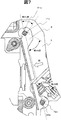
- FIG. 7 is a plan view of the bracket portion, which is drawn from directly above the bracket 6 in FIG. Although part of the bracket 6 is not connected by a solid line in relation to the position where the cross section of the bracket 6 is taken, it is actually integrated as indicated by a broken line.
- 71a and 72a show cross sections of the mounting members 61 and 62 when the previous mounting members 61 and 62 are fastened together with the engine upper case 7 and fixed to the engine bottom 5.
- Reference numerals 61 a and 62 a are attachment holes into which the attachment members 61 and 62 are inserted, and are provided on the bracket 6.
- the cross sections 71a and 72a of the mounting members 61 and 62 are substantially circular.
- the mounting holes 61 a and 62 a are substantially square holes and are provided at an angle of about 45 degrees with respect to the longitudinal direction of the bracket 6. This is one feature of the present embodiment, and the effect of the bracket 6 to reduce the change in the distance between the liquid crystal panel unit 1 and the projection lens 3 is further enhanced. The principle is described below.
- FIG. 7 shows an embodiment in the above case. Needless to say, it is also possible to reduce the decrease in the distance between the liquid crystal panel unit 1 and the projection lens 3 at the time of temperature decrease by setting the pitch dimension.
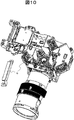
- 8 to 11 are first to fourth external views showing how to attach the bracket. Both show both the external view of the liquid crystal projector and the enlarged view of the bracket 6.
- FIG. 8 shows an example using the same bracket 6 as the liquid crystal projector shown in FIG. 4 and FIG.
- the bracket 6 is fixed to the engine bottom 5 while fastening the prism holder 4 together, using not only the two mounting members 61 and 62 shown in FIG. 6 but also two mounting members.
- FIG. 9 shows an example using two mounting members, but the bracket 6 is fixed to the engine bottom 5 while the prism holder 4 is tightened together.
- the bracket 6 is not necessarily provided on the right side of the figure as in the previous examples.
- the bracket 6 shown in FIG. 6 is provided on the opposite side of the projection lens 3 to the left in the figure, contrary to the example described above.
- the shape of the bracket 6 is a line symmetrical shape with the bracket 6 of FIG.
- the bracket 6 has two brackets 6a and 6b, which are provided on the right side and the left side of the figure. Thereby, the change in the distance between the liquid crystal panel unit 1 and the projection lens 3 is further reduced.
- the bracket 6 is not necessarily provided on the top of the liquid crystal projector as in the previous examples. It may be provided on the lower side across the projection lens 3.
- the shape is not limited to a shape that is long in one direction, and may be, for example, a flat material, and for example, may be a shape that covers the upper side of the prism holder 4. That is, it may be an expansion / contraction prevention member not limited to a bracket having a rod-like planar shape.
- the resin engine bottom when used, it is possible to reduce the defocus of the liquid crystal projector due to the temperature change. Furthermore, there is an effect that the above object can be achieved by a simple and inexpensive structure.
- the embodiments described so far are examples and do not limit the present invention. For example, different embodiments can be considered in the block diagram of the optical system shown in FIG. 1 and the sketches and external views shown in FIG. Thus, although different embodiments can be considered based on the spirit of the present invention, all fall within the scope of the present invention.
- Liquid crystal panel unit 1: Liquid crystal panel unit, 2: Cross prism, 3: Projection lens, 4: Prism holder, 5: Engine bottom, 6: Bracket, 7: Engine upper case, 11: Liquid crystal panel, 12: Polarizing plate, 21: Prism bracket , 31: back spherical lens, 32, 41, 61, 62: mounting member, 42: reference pin, 61a, 62a, 71a, 72a: mounting hole.
Landscapes
- Engineering & Computer Science (AREA)
- Multimedia (AREA)
- Signal Processing (AREA)
- Physics & Mathematics (AREA)
- General Physics & Mathematics (AREA)
- Projection Apparatus (AREA)
Abstract
樹脂材料によるエンジンボトムを有する液晶プロジェクタにおいて、使用中の温度変化によるフォーカスずれを低減する。 投射レンズの取付け位置と液晶パネルの取付け位置に応じたエンジンボトム上の二点間に、金属材料のブラケットを設け、取付け部材で締め付けることで、温度変化によるフォーカスずれを低減する。ブラケットは四角形の取付け孔を備えている。取付け孔は四角形の辺がブラケットの長手方向に対して略45度の角度で設けられ、取付け部材を取付け孔の一辺に圧接するように取付けることで、温度上昇によるフォーカスずれを、さらに低減する。
Description
本発明は液晶プロジェクタに関する。
画像を投射表示するための液晶プロジェクタにおいては、高画質を得るために精度の高いフォーカス性能が要求される。フォーカス性能は投射レンズのみならず、例えば液晶パネル周辺の構成要素にも依存している。温度変化により構成要素の位置が微妙に変わる場合には、使用開始時にユーザが手動でフォーカスを調整したとしても、その後の温度変化によりフォーカスずれが発生する。ユーザが簡単に再度のフォーカス調整を行える場合はまだ良い。しかし、大きな会場で使われるような天井取付け型の装置では、使用中のフォーカス調整は困難である。
特許文献1においては、プロジェクタにおける温度変化による投射レンズの焦点距離の変化を、伸縮部材の温度特性による伸縮で相殺する技術を開示している。
特許文献1においては、プロジェクタにおける温度変化による投射レンズの焦点距離の変化を、伸縮部材の温度特性による伸縮で相殺する技術を開示している。
液晶プロジェクタにおいては、エンジンボトムと称するベースに対して他の主な構成要素が取付けられ、位置決めされている。エンジンボトムの材料には、例えば不飽和ポリエステル樹脂が使用されている。鉄やアルミニウムをはじめとする材料による熱膨張係数の小さい金属ダイキャストを使えば、エンジンボトムの温度変化による伸縮は大幅に改善され、前記したフォーカスずれの問題は改善する。しかし、樹脂や板金と比較して金属ダイキャストは高価であり、量産性にも問題があって好ましくない。
特許文献1は、樹脂によるエンジンボトムを用いる際の問題点の解決方法に係る文献であり、温度補償効果が期待できると思われる。しかし、構造が複雑であり、使用する構成要素の寸法の公差を積み上げると温度補償効果にバラツキが出る恐れもある。樹脂によるエンジンボトムを用いた液晶プロジェクタにおいて、さらに簡素で低価格な構造によりフォーカスずれを低減する方法が望まれる。
本発明の目的は前記した問題に鑑み、温度変化に起因するフォーカスずれを低減した液晶プロジェクタを提供することにある。
本発明の目的は前記した問題に鑑み、温度変化に起因するフォーカスずれを低減した液晶プロジェクタを提供することにある。
前記課題を解決するため本発明は、画像を光学的に投射表示する液晶プロジェクタであって、
投射表示する画像を生成する液晶パネルと、該液晶パネルが生成した画像を外部に投射するための投射レンズと、該投射レンズと前記液晶パネルを含め前記液晶プロジェクタが有する構成要素を固定するための樹脂材料によるエンジンボトムと、該エンジンボトムに対して前記液晶パネルを固定するための第1の取付け部材と、前記エンジンボトムに対して前記投射レンズを固定するための第2の取付け部材と、前記投射レンズの光軸から見た位置が前記第1の取付け部材の近傍に位置する第3の取付け部材と、前記投射レンズの光軸から見た位置が前記第2の取付け部材の近傍に位置する第4の取付け部材と、前記第3の取付け部材と第4の取付け部材により前記エンジンボトムに固定される金属材料による伸縮防止部材を有することを特徴としている。
投射表示する画像を生成する液晶パネルと、該液晶パネルが生成した画像を外部に投射するための投射レンズと、該投射レンズと前記液晶パネルを含め前記液晶プロジェクタが有する構成要素を固定するための樹脂材料によるエンジンボトムと、該エンジンボトムに対して前記液晶パネルを固定するための第1の取付け部材と、前記エンジンボトムに対して前記投射レンズを固定するための第2の取付け部材と、前記投射レンズの光軸から見た位置が前記第1の取付け部材の近傍に位置する第3の取付け部材と、前記投射レンズの光軸から見た位置が前記第2の取付け部材の近傍に位置する第4の取付け部材と、前記第3の取付け部材と第4の取付け部材により前記エンジンボトムに固定される金属材料による伸縮防止部材を有することを特徴としている。
本発明によれば、温度変化に起因するフォーカスずれを低減した液晶プロジェクタを提供でき、液晶プロジェクタの基本性能の向上に寄与できるという効果がある。
以下、本発明の実施例につき図面を用いて説明する。まず液晶プロジェクタの光学エンジンの全般的な構成を説明する。
図1は、液晶プロジェクタの光学エンジンのブロック図を示している。図1で、光源ユニット101は発光部である管球101aと反射面としてのリフレクタ101bを含んでいる。楕円形状のリフレクタ101bの第1焦点位置に配置された管球101aから出射された光束は、リフレクタ101bの第2焦点位置に集光するように前記反射面から反射される。光束サイズを縮小された集光光束は、平行化作用を有する凹レンズ102により平行光束に変換される。なお、リフレクタ101bを放物面形状とした場合は、平行化作用をするための凹レンズ102は不要となる。
図1は、液晶プロジェクタの光学エンジンのブロック図を示している。図1で、光源ユニット101は発光部である管球101aと反射面としてのリフレクタ101bを含んでいる。楕円形状のリフレクタ101bの第1焦点位置に配置された管球101aから出射された光束は、リフレクタ101bの第2焦点位置に集光するように前記反射面から反射される。光束サイズを縮小された集光光束は、平行化作用を有する凹レンズ102により平行光束に変換される。なお、リフレクタ101bを放物面形状とした場合は、平行化作用をするための凹レンズ102は不要となる。
凹レンズ102から出射された平行光束は、第1マルチレンズアレイ103aの各セルレンズにより部分光束に分割されて、第1マルチレンズに対応した第2マルチレンズアレイ103bの各セルレンズ上に集光される。集光された各部分光束は、直線偏光化部104で一旦、振動方向が互いに直交する2つに直線偏光に分離され、さらに一方の直線偏光の振動方向を他方の振動方向に合わせることで、振動方向が一方向の直線偏光に変換される。直線偏光化部104を出射した各部分光束は、重畳レンズ105によりRGB各色用の液晶パネルユニット1R,1G,1Bに重畳して照射される。なお、重畳レンズ105と液晶パネルユニット1R,1G,1Bの間の光路には、光路を折り曲げるための反射ミラー106a,106b,106c,106dと、色分解光学部としてのダイクロイックミラー107aと107bが設けられ、さらに各液晶パネルユニット1R,1G,1Bの手前には、投射光束の主光線を平行化するコリメータレンズ108R,108G,108Bが配置される。緑色や青色よりも光路長の長い赤色の光路には、重畳した光束を赤色用の液晶パネルユニット1Rの位置に写像するためのリレーレンズ109と110が配置されている。
このようにして液晶パネルユニット1R,1G,1Bに供給された管球101aからの光束は、液晶パネルユニット1R,1G,1Bの各々に別途供給される映像R信号、映像G信号、映像B信号のレベルに応じて液晶パネルを通過できる量を変化される。これにより、前記光束に映像信号の情報が与えられる。このために、液晶パネルユニット1R,1G,1Bは液晶パネルのみならず、所定の振動方向の光束を通過させるための偏光板を備えている。
液晶パネルユニット1R,1G,1Bを通過した各光束は、クロスプリズム2で互いに合成され、投射レンズ3を介して外部に設けられたスクリーン(図示せず)に前記映像信号に応じた映像を表示する。
液晶パネルユニット1R,1G,1Bを通過した各光束は、クロスプリズム2で互いに合成され、投射レンズ3を介して外部に設けられたスクリーン(図示せず)に前記映像信号に応じた映像を表示する。
以下、本実施例では前記したフォーカス性能について述べるため、液晶パネルユニット1R,1G,1B、クロスプリズム2、投射レンズ3、及びその周辺について詳しく説明する。なお、1R,1G,1Gの液晶パネルユニットに共通する事項を述べる際は、単に液晶パネルユニット1と記すことがある。
図2は、液晶プロジェクタの投射レンズ3付近の見取り図である。ここでは、図1のブロック図に対して左側の側面より見た、液晶パネルユニット1(図示する都合上1Gのみを示す)、クロスプリズム2、投射レンズ3とこれらの周辺を示している。
図2は、液晶プロジェクタの投射レンズ3付近の見取り図である。ここでは、図1のブロック図に対して左側の側面より見た、液晶パネルユニット1(図示する都合上1Gのみを示す)、クロスプリズム2、投射レンズ3とこれらの周辺を示している。
液晶プロジェクタのベースであるエンジンボトム5(図中に右上から左下方向の斜線を付す)には、多くの構成要素が取付けられるが、構成要素によっては、他の構成要素を介してエンジンボトム5に取付けられる。
投射レンズ3は、ネジをはじめとする固定部材32を用いてエンジンボトム5に取付けられ、固定される。
クロスプリズム2は、プリズムホルダ4(図中に左上から右下方向の斜線を付す)に対して固定される。プリズムホルダ4はエンジンボトム5に対して、まず基準ピン42で位置決めされた後に、ネジをはじめとする固定部材41を用いて固定される。即ち、クロスプリズム2は、プリズムホルダ4を介してエンジンボトム5に取付けられ、固定される。
投射レンズ3は、ネジをはじめとする固定部材32を用いてエンジンボトム5に取付けられ、固定される。
クロスプリズム2は、プリズムホルダ4(図中に左上から右下方向の斜線を付す)に対して固定される。プリズムホルダ4はエンジンボトム5に対して、まず基準ピン42で位置決めされた後に、ネジをはじめとする固定部材41を用いて固定される。即ち、クロスプリズム2は、プリズムホルダ4を介してエンジンボトム5に取付けられ、固定される。
なお、固定部材32と41につき、図面の煩雑化を避けるため図2では1個のみに符号を付している。固定部材32は投射レンズ3の周辺部に4個程度、固定部材41はプリズムホルダ4の周辺部に3個程度設けられることが多い。
液晶パネル11を備える液晶パネルユニット1は取付け孔を有しており、クロスプリズム2が有するパネルブラケット21(21a,21b)が挿入されることでクロスプリズム2に取付けられ、固定される。即ち、液晶パネルユニット1は、パネルブラケット21、クロスプリズム2、プリズムホルダ4を介してエンジンボトム5に取付けられ、固定される。
液晶パネル11を備える液晶パネルユニット1は取付け孔を有しており、クロスプリズム2が有するパネルブラケット21(21a,21b)が挿入されることでクロスプリズム2に取付けられ、固定される。即ち、液晶パネルユニット1は、パネルブラケット21、クロスプリズム2、プリズムホルダ4を介してエンジンボトム5に取付けられ、固定される。
ここでフォーカスずれを起こさないためには、投射レンズ3と液晶パネル11の光学的な距離を一定に保つことが重要である。現在使われている光学系では、前記距離が1μmずれると、例えば10cm程度の焦点距離のずれが発生することがあり、温度特性による前記距離の変化に対しては充分な配慮が必要である。
図3は、クロスプリズム2の周辺の分解図であり、図1の斜め左上方向から描いた図である。液晶パネルユニット1は、液晶パネル11と偏光板12を備える。クロスプリズム2は、プリズムホルダ4に固定される。クロスプリズム2の上下に有するパネルブラケット21a,21bが、液晶パネル11の周辺の取付け孔(図3では液晶パネル1個当たり4箇所)に挿入され、液晶パネルユニット1をクロスプリズム2に固定する。プリズムホルダ4の周辺部には、ネジをはじめとする固定部材41(図示せず)を通す取付け孔41aが設けられており、取付け孔41aを通して固定部材41がプリズムホルダ4を先のエンジンボトム5に固定する。取付け孔41aは図3では1個のみ符号を付しているが、前記したようにプリズムホルダ4の周辺部に3個程度設けると良い。
なお、液晶パネル11から上方に伸びる部材は、液晶パネル11に映像信号を供給するためのフレキシブル基板である。パネルブラケット21a,21bは、液晶パネルユニット1が3個あるために計12個の凸部が設けられているが、図3では他の構成要素の陰に入るものがあるため、計6個が描かれている。図面の煩雑化を避けるため、その一部のみに符号を付している。また、ブラケット6については後に詳しく説明するが、ここでは形状の一例と概略の位置を示している。
図4は、液晶プロジェクタの光学エンジンの第1の外観図であり、図3と同様な方向から描いている。液晶パネルユニット1を周辺に取付けたクロスプリズム2は、上方に外された状態となっている。
図5は、液晶プロジェクタの光学エンジンの第2の外観図であり、図3と同様な方向から描いている。図4とは異なり、液晶パネルユニット1を周辺に取付けたクロスプリズム2は、所定の取付け位置において、エンジンボトム5に取付けられている。このため、クロスプリズム2の上方にあるプリズムホルダ4が主に描かれている。
図5は、液晶プロジェクタの光学エンジンの第2の外観図であり、図3と同様な方向から描いている。図4とは異なり、液晶パネルユニット1を周辺に取付けたクロスプリズム2は、所定の取付け位置において、エンジンボトム5に取付けられている。このため、クロスプリズム2の上方にあるプリズムホルダ4が主に描かれている。
前記した温度変化によるフォーカスのずれは、液晶パネルユニット1と投射レンズ3の距離が、温度によって変化することに起因している。この距離をより具体的に定義すれば、図2の液晶パネル11の表示面と投射レンズ3が含む後球レンズ31の間の距離Pとなる。図2から分かるように、液晶パネル11と投射レンズ3の距離Pは、主にパネルブラケット21、プリズムホルダ4、エンジンボトム5の伸縮により変化する可能性がある。
クロスプリズム2と液晶パネルユニット1の相対的な位置は、パネルブラケット21で規定されている。パネルブラケットは部品の体積が小さいこともあって、例えば鉄材を用いることができるため、温度変化に対する伸縮は殆ど問題にならない。これに対して、プリズムホルダ4やエンジンボトム5については、金属材料を用いるとコストや量産性で問題があり、さらには重量が増加する問題がある。このため、例えばポリフェニルエーテルとポリスチレンを含む樹脂や不飽和ポリエステルが使われることが多い。樹脂を使用する場合は、温度変化による伸縮が問題となる。特に、サイズの大きいエンジンボトム5の伸縮は、液晶パネルユニット1と投射レンズ3の距離Pを変化させて、使用中のフォーカスずれを引き起こす大きな要因となる。
図6は、液晶プロジェクタの光学エンジンの第1の外観図であり、先の図4や図5でも示されていたブラケット6の取付け方法も含め図示されている。なお、後記するようにブラケット6の形状は、図4や図5で示したものとはいくらか異なっている。本実施例においては、例えばステンレス材によるブラケット6を用いて、液晶パネルユニット1と投射レンズ3の距離の変化を低減することを一つの特徴としている。
図6でエンジンアッパーケース7は、エンジンボトム5の上側に取付けられるケースであって、例えばポリカーボネート樹脂で作られている。ブラケット6は、例えばネジをはじめとする取付け部材61と62によりエンジンボトム5に取付けられるが、ここでは取付け部材61と62は、ブラケット6とエンジンアッパーケース7を共締めする場合を示している。
投射レンズ3の光軸であるZ軸上での(図2において矢印Aで示す方向に見た場合の)構成要素の位置を説明する。取付け部材61はZ軸上から見て(矢印Aで示す方向に見て)取付け部材41または基準ピン42と同じか近傍に設けられており、ブラケット6をエンジンボトム5に固定する。一方、取付け部材62はZ軸上から見て(矢印Aで示す方向に見て)取付け部材32への取付け位置と同じか近傍に設けられており、ブラケット6をエンジンボトム5に固定する。ブラケット6は例えばステンレス材で作られており、エンジンボトム5と比較して温度変化による伸縮は遥かに小さく、剛性は大きい。このため、温度が変化することによる液晶パネルユニット1と投射レンズ3の距離の変化は、ブラケット6の作用により大幅に低減される。これにより使用中にフォーカスがずれる問題は解消される。
次に、ブラケット6の取付け方法をさらに詳しく説明する。
図7は、ブラケット部の平面図であり、図6におけるブラケット6の真上から描いた図である。ブラケット6の断面を取る位置の関係で一部が実線で接続されていないが、実際には破線で示すように一体となっている。71aと72aは、先の取付け部材61と62がエンジンアッパーケース7と共締めされ、エンジンボトム5に固定されている時の取付け部材61と62の断面を示している。61aと62aは、先の取付け部材61と62が挿入される取付け孔であり、ブラケット6に設けられている。
図7は、ブラケット部の平面図であり、図6におけるブラケット6の真上から描いた図である。ブラケット6の断面を取る位置の関係で一部が実線で接続されていないが、実際には破線で示すように一体となっている。71aと72aは、先の取付け部材61と62がエンジンアッパーケース7と共締めされ、エンジンボトム5に固定されている時の取付け部材61と62の断面を示している。61aと62aは、先の取付け部材61と62が挿入される取付け孔であり、ブラケット6に設けられている。
ここでは、取付け部材61と62の断面71aと72aはほぼ円形である。一方、取付け孔61aと62aはほぼ四角形の孔であり、ブラケット6の長手方向に対して略45度の角度で設けられている。これは、本実施例の一つの特徴であり、ブラケット6が液晶パネルユニット1と投射レンズ3の距離の変化を低減する効果を、いっそう高めるようにしている。その原理を下記に記す。
ブラケット6を取付ける際に、取付け部材61を取付け孔61aに通して仮止めし、次に取付け部材62を取付け孔62aに通して先のエンジンボトム5に仮止めした後、図中の矢印Bで示す方向に向け作業者がブラケット6に力を加える。この時、取付け部材61が四角形をした取付け孔61aの二辺に当接するよう取付け部材61を最初に締め込む。次に、再度矢印Bで示す方向に力を加えながら取付け部材62を締め込むことで、取付け部材62は四角形をした取付け孔62aの一辺と当接させることができる。使用中の温度変化については、多くの場合で温度上昇が問題である。前記したブラケット6の取付け孔61aと62aのピッチ寸法を設定することにより、使用中の温度上昇により液晶パネルユニット1と投射レンズ3の距離が増加する方向となる際に、取付け部材62とブラケット6の取付け孔62aが強く噛み合うことで、前記した距離の増加を低減することができる。図7は、前記の場合の実施例を示している。
また、ピッチ寸法の設定により、温度下降時に液晶パネルユニット1と投射レンズ3の距離が減少することを低減することも可能であることはいうまでもない。
また、ピッチ寸法の設定により、温度下降時に液晶パネルユニット1と投射レンズ3の距離が減少することを低減することも可能であることはいうまでもない。
次に、ブラケット6の異なる例を説明する。
図8から図11は、ブラケットの取付け方法を示す第1から第4の外観図である。いずれも液晶プロジェクタの外観図と、ブラケット6の拡大図の双方を示している。
図8から図11は、ブラケットの取付け方法を示す第1から第4の外観図である。いずれも液晶プロジェクタの外観図と、ブラケット6の拡大図の双方を示している。
図8は、先の図4と図5で示した液晶プロジェクタと同様なブラケット6を用いた例を示す。ブラケット6は、図6で示した二つの取付け部材61と62のみならず、さらに二つの取付け部材を用いて、プリズムホルダ4を共締めしながらエンジンボトム5に固定される。
図9は、二つの取付け部材を用いる例であるが、ブラケット6は、プリズムホルダ4を共締めしながらエンジンボトム5に固定される。
図9は、二つの取付け部材を用いる例であるが、ブラケット6は、プリズムホルダ4を共締めしながらエンジンボトム5に固定される。
もちろん、ブラケット6は、これまでの例のように図の右手寄りに設けられるとは限らない。図10においては、図6で示したブラケット6は、これまでの例とは逆に投射レンズ3を挟んで図の左手寄りに設けられている。もちろんブラケット6の形状は、図6のブラケット6と線対称な形状である。また、図11においてブラケット6は2個のブラケット6aと6bを有しており、図の右手寄りと左手寄りに設けられている。これにより、液晶パネルユニット1と投射レンズ3の距離の変化をいっそう低減している。
また、これまでの例のようにブラケット6を液晶プロジェクタの上部に設けられるとは限らない。投射レンズ3を挟んで下部に設けられても良い。さらに、一方向に長い形状に限らず、例えば平面材であっても良く、例えばプリズムホルダ4の上側をカバーする形状であっても良い。即ち、棒状の平面形状を有するブラケットに限定されない伸縮防止部材であって良い。
いずれの場合においても本実施例によれば、樹脂のエンジンボトムを用いた場合において、温度変化による液晶プロジェクタのフォーカスずれを低減できる。さらには、簡素で低価格な構造により前記目的を達成できるという効果がある。
ここまで示した実施形態は一例であって、本発明を限定するものではない。例えば、図1に示した光学系のブロック図、図2以降で示した見取り図や外観図において、異なる実施形態を考えることができる。このように、本発明の趣旨に基づきながら異なる実施形態を考えられるが、いずれも本発明の範疇にある。
いずれの場合においても本実施例によれば、樹脂のエンジンボトムを用いた場合において、温度変化による液晶プロジェクタのフォーカスずれを低減できる。さらには、簡素で低価格な構造により前記目的を達成できるという効果がある。
ここまで示した実施形態は一例であって、本発明を限定するものではない。例えば、図1に示した光学系のブロック図、図2以降で示した見取り図や外観図において、異なる実施形態を考えることができる。このように、本発明の趣旨に基づきながら異なる実施形態を考えられるが、いずれも本発明の範疇にある。
1:液晶パネルユニット、2:クロスプリズム、3:投射レンズ、4:プリズムホルダ、5:エンジンボトム、6:ブラケット、7:エンジンアッパーケース、11:液晶パネル、12:偏光板、21:プリズムブラケット、31:後球レンズ、32,41,61,62:取付け部材、42:基準ピン、61a,62a,71a,72a:取付け孔。
Claims (5)
- 画像を光学的に投射表示する液晶プロジェクタであって、
投射表示する画像を生成する液晶パネルと、
該液晶パネルが生成した画像を外部に投射するための投射レンズと、
該投射レンズと前記液晶パネルを含め前記液晶プロジェクタが有する構成要素を固定するための樹脂材料によるエンジンボトムと、
該エンジンボトムに対して前記液晶パネルを固定するための第1の取付け部材と、
前記エンジンボトムに対して前記投射レンズを固定するための第2の取付け部材と、
前記投射レンズの光軸から見た位置が前記第1の取付け部材の近傍に位置する第3の取付け部材と、
前記投射レンズの光軸から見た位置が前記第2の取付け部材の近傍に位置する第4の取付け部材と、
前記第3の取付け部材と第4の取付け部材により前記エンジンボトムに固定される金属材料による伸縮防止部材
を有することを特徴とする液晶プロジェクタ。 - 請求項1に記載の液晶プロジェクタにおいて、
前記液晶パネルは映像赤信号、緑信号、青信号に応じた3個の液晶パネルを備え、
前記液晶プロジェクタは前記3個の液晶パネルが生成した画像を合成するクロスプリズムを備え、
前記液晶パネルは前記クロスプリズムを介して前記エンジンボトムに固定されることを特徴とする液晶プロジェクタ。 - 請求項1に記載の液晶プロジェクタにおいて、前記伸縮防止部材は、棒状の平面形状を有するブラケットであることを特徴とする液晶プロジェクタ。
- 請求項3に記載の液晶プロジェクタにおいて、前記ブラケットは、前記エンジンボトムの異なる位置に取付けられる複数のブラケットを含むことを特徴とする液晶プロジェクタ。
- 請求項1に記載の液晶プロジェクタにおいて、
前記伸縮防止部材は、前記第3の取付け部材を通すための略四角形の第1の取付け孔と、前記第4の取付け部材を通すための略四角形の第2の取付け孔を有し、
第1の取付け孔と第2の取付け孔を結ぶ軸に対して略45度傾いた方向に、前記第1及び第2の取付け孔の辺を3つ以上有し、
前記第3及び第4の取付け部材は、前記略45度傾いた3つ以上の辺に当接して取付けられることを特徴とする液晶プロジェクタ。
Priority Applications (2)
| Application Number | Priority Date | Filing Date | Title |
|---|---|---|---|
| PCT/JP2011/052784 WO2012108018A1 (ja) | 2011-02-09 | 2011-02-09 | 液晶プロジェクタ |
| JP2012556701A JP5651715B2 (ja) | 2011-02-09 | 2011-02-09 | 液晶プロジェクタ |
Applications Claiming Priority (1)
| Application Number | Priority Date | Filing Date | Title |
|---|---|---|---|
| PCT/JP2011/052784 WO2012108018A1 (ja) | 2011-02-09 | 2011-02-09 | 液晶プロジェクタ |
Publications (1)
| Publication Number | Publication Date |
|---|---|
| WO2012108018A1 true WO2012108018A1 (ja) | 2012-08-16 |
Family
ID=46638261
Family Applications (1)
| Application Number | Title | Priority Date | Filing Date |
|---|---|---|---|
| PCT/JP2011/052784 Ceased WO2012108018A1 (ja) | 2011-02-09 | 2011-02-09 | 液晶プロジェクタ |
Country Status (2)
| Country | Link |
|---|---|
| JP (1) | JP5651715B2 (ja) |
| WO (1) | WO2012108018A1 (ja) |
Citations (4)
| Publication number | Priority date | Publication date | Assignee | Title |
|---|---|---|---|---|
| JP2005346089A (ja) * | 2001-08-08 | 2005-12-15 | Seiko Epson Corp | 光学装置、光学装置の製造方法、およびプロジェクタ |
| JP2008083499A (ja) * | 2006-09-28 | 2008-04-10 | Seiko Epson Corp | 光変調装置、及びプロジェクタ |
| JP2008241895A (ja) * | 2007-03-26 | 2008-10-09 | Seiko Epson Corp | プロジェクタ |
| JP2010256394A (ja) * | 2009-04-21 | 2010-11-11 | Seiko Epson Corp | プロジェクター |
-
2011
- 2011-02-09 WO PCT/JP2011/052784 patent/WO2012108018A1/ja not_active Ceased
- 2011-02-09 JP JP2012556701A patent/JP5651715B2/ja not_active Expired - Fee Related
Patent Citations (4)
| Publication number | Priority date | Publication date | Assignee | Title |
|---|---|---|---|---|
| JP2005346089A (ja) * | 2001-08-08 | 2005-12-15 | Seiko Epson Corp | 光学装置、光学装置の製造方法、およびプロジェクタ |
| JP2008083499A (ja) * | 2006-09-28 | 2008-04-10 | Seiko Epson Corp | 光変調装置、及びプロジェクタ |
| JP2008241895A (ja) * | 2007-03-26 | 2008-10-09 | Seiko Epson Corp | プロジェクタ |
| JP2010256394A (ja) * | 2009-04-21 | 2010-11-11 | Seiko Epson Corp | プロジェクター |
Also Published As
| Publication number | Publication date |
|---|---|
| JPWO2012108018A1 (ja) | 2014-07-03 |
| JP5651715B2 (ja) | 2015-01-14 |
Similar Documents
| Publication | Publication Date | Title |
|---|---|---|
| US11448951B2 (en) | Projection lens and projector | |
| US7984994B2 (en) | Image display apparatus | |
| JP5358451B2 (ja) | 面状照明装置及び画像表示装置 | |
| JP4055774B2 (ja) | プリズム構造体およびプロジェクタ | |
| JP5790206B2 (ja) | プロジェクター | |
| WO2002069018A1 (en) | Lighting optical system, and projector using the same | |
| CN107209444B (zh) | 激光光源装置和视频显示装置 | |
| JP6524672B2 (ja) | プロジェクター | |
| US7416307B2 (en) | Optical apparatus and projection apparatus | |
| WO2013054427A1 (ja) | 投写型映像表示装置 | |
| JP5651715B2 (ja) | 液晶プロジェクタ | |
| JP2007212496A (ja) | 光学装置及びプロジェクタ並びに光学装置の製造方法 | |
| CN104756006B (zh) | 投影型影像显示装置 | |
| CN100388055C (zh) | 光学仪器和投影仪器 | |
| JP2016085443A (ja) | 光学補償素子調整機構及びプロジェクター | |
| JP4679868B2 (ja) | 投射装置 | |
| JP2007328086A (ja) | 投写光学系及びプロジェクタ | |
| JP2007240692A (ja) | リアプロジェクタ | |
| JP2016012135A (ja) | プロジェクター | |
| JP2017032618A (ja) | 画像投射装置 | |
| JP2004053703A (ja) | 偏光変換素子及び、それを用いた液晶プロジェクタ装置 | |
| JP2011164147A (ja) | 反射型液晶表示装置 | |
| JP2007219132A (ja) | プロジェクタの製造方法 | |
| JP2014186086A (ja) | プロジェクター | |
| JP2007047360A (ja) | 投射型画像表示装置 |
Legal Events
| Date | Code | Title | Description |
|---|---|---|---|
| 121 | Ep: the epo has been informed by wipo that ep was designated in this application |
Ref document number: 11858303 Country of ref document: EP Kind code of ref document: A1 |
|
| ENP | Entry into the national phase |
Ref document number: 2012556701 Country of ref document: JP Kind code of ref document: A |
|
| NENP | Non-entry into the national phase |
Ref country code: DE |
|
| 122 | Ep: pct application non-entry in european phase |
Ref document number: 11858303 Country of ref document: EP Kind code of ref document: A1 |