WO2012105528A1 - バッテリー交換ロボット - Google Patents
バッテリー交換ロボット Download PDFInfo
- Publication number
- WO2012105528A1 WO2012105528A1 PCT/JP2012/052062 JP2012052062W WO2012105528A1 WO 2012105528 A1 WO2012105528 A1 WO 2012105528A1 JP 2012052062 W JP2012052062 W JP 2012052062W WO 2012105528 A1 WO2012105528 A1 WO 2012105528A1
- Authority
- WO
- WIPO (PCT)
- Prior art keywords
- battery
- rotation
- guide block
- guide rail
- disposed
- Prior art date
- Legal status (The legal status is an assumption and is not a legal conclusion. Google has not performed a legal analysis and makes no representation as to the accuracy of the status listed.)
- Ceased
Links
Images













Classifications
-
- B—PERFORMING OPERATIONS; TRANSPORTING
- B60—VEHICLES IN GENERAL
- B60K—ARRANGEMENT OR MOUNTING OF PROPULSION UNITS OR OF TRANSMISSIONS IN VEHICLES; ARRANGEMENT OR MOUNTING OF PLURAL DIVERSE PRIME-MOVERS IN VEHICLES; AUXILIARY DRIVES FOR VEHICLES; INSTRUMENTATION OR DASHBOARDS FOR VEHICLES; ARRANGEMENTS IN CONNECTION WITH COOLING, AIR INTAKE, GAS EXHAUST OR FUEL SUPPLY OF PROPULSION UNITS IN VEHICLES
- B60K1/00—Arrangement or mounting of electrical propulsion units
- B60K1/04—Arrangement or mounting of electrical propulsion units of the electric storage means for propulsion
-
- B—PERFORMING OPERATIONS; TRANSPORTING
- B60—VEHICLES IN GENERAL
- B60K—ARRANGEMENT OR MOUNTING OF PROPULSION UNITS OR OF TRANSMISSIONS IN VEHICLES; ARRANGEMENT OR MOUNTING OF PLURAL DIVERSE PRIME-MOVERS IN VEHICLES; AUXILIARY DRIVES FOR VEHICLES; INSTRUMENTATION OR DASHBOARDS FOR VEHICLES; ARRANGEMENTS IN CONNECTION WITH COOLING, AIR INTAKE, GAS EXHAUST OR FUEL SUPPLY OF PROPULSION UNITS IN VEHICLES
- B60K1/00—Arrangement or mounting of electrical propulsion units
- B60K1/04—Arrangement or mounting of electrical propulsion units of the electric storage means for propulsion
- B60K2001/0455—Removal or replacement of the energy storages
- B60K2001/0461—Removal or replacement of the energy storages from the side
-
- B—PERFORMING OPERATIONS; TRANSPORTING
- B60—VEHICLES IN GENERAL
- B60Y—INDEXING SCHEME RELATING TO ASPECTS CROSS-CUTTING VEHICLE TECHNOLOGY
- B60Y2200/00—Type of vehicle
- B60Y2200/10—Road Vehicles
- B60Y2200/14—Trucks; Load vehicles, Busses
- B60Y2200/143—Busses
Definitions
- the present invention relates to a battery exchange robot for exchanging a battery mounted on a vehicle.
- a battery exchange device for exchanging a battery mounted on an electric bus has been proposed (see, for example, Patent Document 1).
- a battery exchange device described in Patent Document 1 includes a battery tray on which a battery is mounted, a vertical lift device that raises and lowers the battery tray, a rotary platform that is mounted with the battery tray and the vertical lift device, and is rotatable, and a rotary platform And a parallel movement platform movable in the horizontal direction.
- a battery compartment is generally attached to the lower side of the seat. That is, in the case of an electric bus, the battery is mounted at a relatively low position. Therefore, when the battery of the electric bus is replaced, it is necessary to pull out or insert the battery at a relatively low position.
- an object of the present invention is to provide a battery exchange robot capable of appropriately replacing a battery mounted on a vehicle even when the battery is mounted on a relatively low position of the vehicle.
- a battery exchange robot of the present invention is a battery exchange robot for exchanging a battery mounted on a vehicle, and a direction in which the vehicle and the battery exchange robot face each other is a front-rear direction,
- a battery insertion / removal mechanism that pulls out the battery from the vehicle and / or inserts the battery into the vehicle
- a lifting mechanism that raises and lowers the battery insertion / removal mechanism
- a rotation mechanism that rotates the battery insertion / removal mechanism and the lifting mechanism with the vertical direction as an axial direction
- a horizontal movement mechanism that moves the battery insertion / removal mechanism, the lifting mechanism and the rotation mechanism in the left-right direction
- An elevating member that moves up and down together with the battery insertion / removal mechanism, and a columnar member that holds the elevating member so as to be movable
- the rotation mechanism includes a rotation member that can rotate while the columnar member is fixed to the upper surface thereof,
- the rotation mechanism includes, as a rotation guide block, at least one first rotation guide block disposed on the lower side or the lower side of the columnar member when the battery is pulled out and / or inserted. And at least one second rotation guide block arranged on the upper side of the linear motion guide block or in the vicinity of the upper side.
- At the time of removing or inserting the battery at least one first rotation guide block is disposed on the lower side or the lower side of the columnar member. Therefore, when the battery is pulled out or inserted, the battery is mounted on the battery pulling mechanism and a large load is applied to the columnar member. However, when the battery is pulled out or inserted, the columnar member fixed to the upper surface side of the rotating member is used. Such a large load can be directly received by the first rotation guide block and the rotation guide rail disposed on the lower surface side of the rotation member. Therefore, in the present invention, even if the rotating member is thinned to reduce the rigidity of the rotating member, the rotating member can be prevented from being deformed. That is, in the present invention, the rotating member can be made thin.
- the load transmitted from the columnar member to the rotating member is distributed and transmitted to the plurality of rotating guide blocks.
- at least one second rotation is performed when the battery is pulled out or inserted. Since the moving guide block is arranged on the upper side or in the vicinity of the upper side of the linear guide block, the load distributed and transmitted to the second rotating guide block arranged on the upper surface side of the slide member is transferred to the lower surface side of the slide member. It becomes possible to receive directly with the linear motion guide block and linear motion guide rail which are arrange
- the rotating member and the slide member can be made thinner. Therefore, in the present invention, it is possible to lower the battery insertion / removal mechanism arranged above the rotating member and the slide member to a relatively low position, and even if the battery is mounted at a relatively low position of the vehicle, The battery mounted on the vehicle can be properly pulled out and inserted by the battery insertion / removal mechanism. That is, according to the present invention, even if a battery is mounted at a relatively low position in the vehicle, it is possible to appropriately replace the battery mounted in the vehicle.
- the second rotation guide block is disposed between the plurality of linear motion guide blocks in the left-right direction when the battery is pulled out and / or inserted. If comprised in this way, it will become possible to support the part to which the load transmitted to the 2nd rotation guide block of a slide member acts on both sides of the left-right direction with a linear motion guide block and a linear motion guide rail. Therefore, it is possible to effectively prevent deformation of the slide member.
- the linear motion guide rail is disposed between the plurality of rotation guide blocks in the front-rear direction when the battery is pulled out and / or inserted. If comprised in this way, it will become possible to arrange
- the rotation guide block is preferably fixed to the rotation member, and the rotation guide rail is preferably fixed to the slide member. If comprised in this way, a rotation guide block will rotate with a rotation member. That is, the first rotation guide block rotates together with the rotation member. Therefore, even if the rotating member rotates, the load applied to the columnar member can be directly received by the first rotating guide block and the rotating guide rail.
- the rotation mechanism preferably includes a drive source for rotating the rotation member, and the drive source is preferably arranged on the radially outer side of the rotation member. If comprised in this way, since a drive source is not arrange
- the rotation mechanism includes a motor as a drive source, a toothed pulley fixed to the output shaft of the motor, and a toothed belt that is bridged between the toothed pulley and the rotation member. It is preferable that one surface on which the teeth of the belt are formed is in contact with the outer peripheral surface of the toothed pulley, and the other flat surface of the toothed belt is in contact with the outer peripheral surface of the rotating member. If comprised in this way, since it becomes unnecessary to form a tooth
- a part of the toothed belt is preferably fixed to the outer peripheral surface of the rotating member. If comprised in this way, even if a tooth
- the battery insertion / removal mechanism is movable in a direction approaching the vehicle and in a direction away from the vehicle, and a direction approaching the vehicle when the battery is withdrawn and / or inserted in order to remove and / or insert the battery.
- the lifting mechanism includes two columnar members disposed on both ends of the first direction orthogonal to the moving direction of the movable unit and the vertical direction.
- At least one first rotation guide block is disposed on the lower side or in the vicinity of the lower side.
- the battery replacement robot of the present invention it is possible to appropriately replace the battery mounted on the vehicle even if the battery is mounted at a relatively low position of the vehicle.
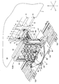
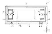
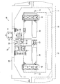
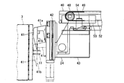
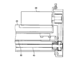
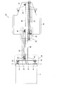
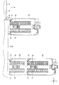
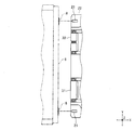
- FIG. 1 is a perspective view of a battery exchange system in which a battery exchange robot according to an embodiment of the present invention is used. It is a perspective view which shows the E section of FIG. 1 from another angle. It is an enlarged view of the F section of FIG. It is a front view which shows the state in which the battery was accommodated in the battery accommodating part shown in FIG. It is an enlarged view of the G section of FIG. It is a figure which shows the battery insertion / extraction mechanism and lifting mechanism shown in FIG. 2 from the front. It is a figure which shows a battery insertion / extraction mechanism and a raising / lowering mechanism from the HH direction of FIG. It is a figure for demonstrating the battery mounting mechanism shown in FIG. 6 from the front.
- FIG. 7A is a diagram for explaining the battery moving mechanism shown in FIG. 6 from an upper surface.
- (A) is an enlarged view of a portion M in FIG. 18, and (B) is an enlarged view of a portion N in FIG. It is a figure for demonstrating the raising / lowering mechanism shown in FIG. 6 from an upper surface.
- FIGS. 7A and 7B are diagrams for explaining the configuration of the first coupling mechanism shown in FIG. 6.
- FIG. 7A is a diagram for explaining the first coupling mechanism from the front, and FIG. It is a figure for demonstrating 1 connection mechanism.
- FIGS. 7A and 7B are diagrams for explaining the configuration of the second coupling mechanism shown in FIG. 6.
- FIG. 7A is a diagram for explaining the second coupling mechanism from the front, and FIG.
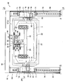
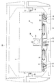
- FIG. 2 It is a figure for demonstrating 2 connection mechanisms. It is a figure for demonstrating a state when the holding member shown in FIG. 6 is inclined from the front. It is a figure for demonstrating the rotation mechanism and horizontal movement mechanism which are shown in FIG. 2 from the front. It is a figure for demonstrating the rotation mechanism and horizontal movement mechanism which are shown in FIG. 2 from the upper surface. It is a figure for demonstrating a rotation mechanism and a horizontal movement mechanism from the RR direction of FIG. (A) is an enlarged view of the U part of FIG. 25, (B) is an enlarged view of the V part of FIG. It is a figure for demonstrating the detection method of the approximate position of the battery by the detection mechanism shown in FIG.
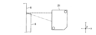
- FIG. It is a figure for demonstrating the detection method of the position of the battery by the detection mechanism shown in FIG. It is a figure for demonstrating the attachment method of the detection mechanism concerning other embodiment of this invention. It is a figure for demonstrating the effect when a detection mechanism is attached with the attachment method shown in FIG. (A) is a figure for demonstrating from the front the detection mark concerning other embodiment of this invention, (B) is sectional drawing of the WW cross section of (A).
- FIG. 1 is a perspective view of a battery exchange system 1 in which a battery exchange robot 5 according to an embodiment of the present invention is used.
- FIG. 2 is a perspective view showing the E portion of FIG. 1 from another angle.
- each of the three directions orthogonal to each other is defined as an X direction, a Y direction, and a Z direction.
- the Z direction coincides with the vertical direction (vertical direction).
- the X direction is the front-rear direction and the Y direction is the left-right direction.
- the battery exchange robot 5 (hereinafter referred to as “robot 5”) of this embodiment is a robot for exchanging the battery 3 mounted on the vehicle 2, and is used in the battery exchange system 1.
- the vehicle 2 of this embodiment is an electric bus. Therefore, hereinafter, the vehicle 2 is referred to as “bus 2”.
- a battery housing portion 4 in which a plurality of batteries 3 are housed is attached to the bus 2.
- the battery accommodating portion 4 is arranged so as to be exposed to the side surface 2a when a cover member (not shown) attached to one side surface 2a of the bus 2 is removed. Further, the battery accommodating portion 4 is disposed below the seat of the bus 2. That is, the battery 3 is mounted at a relatively low position on the bus 2. When the battery 3 is replaced, the bus 2 is stopped so that the traveling direction thereof substantially coincides with the left-right direction.
- the robot 5 faces the side surface 2a of the bus 2 in the front-rear direction so that the battery 3 housed in the battery housing portion 4 can be replaced.
- the robot 5 pulls out the battery 3 housed in the battery housing portion 4 and carries it into a buffer station (not shown), and unloads the charged battery 3 housed in the buffer station from the buffer station. Insert into the housing 4.
- FIG. 3 is an enlarged view of a portion F in FIG.
- FIG. 4 is a front view showing a state in which the battery 3 is accommodated in the battery accommodating portion 4 shown in FIG.
- FIG. 5 is an enlarged view of a portion G in FIG.
- the battery housing part 4 includes a battery cradle 6 on which the battery 3 is mounted and left and right side walls 7, and the battery cradle 6 and the side walls 7 form a housing space for the battery 3.
- accommodating spaces for a plurality of batteries 3 are formed, and a plurality of batteries 3 can be accommodated.
- the battery accommodating part 4 is arrange
- a detection mark 8 for indirectly detecting the position of the battery 3 is formed on the front surface of the battery stand 6.
- the detection mark 8 is formed on each of both ends in the left-right direction of the battery mount 6. Further, as shown in FIG. 3, the detection mark 8 is formed in a flat plate shape that protrudes from the front surface of the battery mount 6, and is formed in a substantially triangular shape whose width changes in the vertical direction.
- the detection mark 8 is fixed to the flat plate member 9, and the flat plate member 9 is fixed to the front surface of the battery table 6, whereby the front surface of the battery table 6.
- a detection mark 8 is formed on the surface.
- a handle portion 11 for pulling out the battery 3 from the battery housing portion 4 is formed on the front surface of the battery 3.
- the handle portion 11 is formed on each of the left and right ends of the front surface of the battery 3.
- a protrusion 12 for positioning the battery 3 pulled out by the robot 5 in a direction orthogonal to the pulling direction is formed so as to protrude downward (see FIG. 5).
- the battery 3 includes a fixing member 13 (see FIG. 4) for fixing the battery 3 to the battery housing portion 4 and a release member 14 (see FIG. 3) for releasing the fixed state of the battery 3 with respect to the battery housing portion 4. ).
- the fixing member 13 is attached to the battery 3 so as to protrude from the left and right side surfaces of the battery 3.
- the fixing member 13 is attached to the front side of the battery 3.
- the fixing member 13 is held by the battery 3 so as to be movable in the left-right direction.
- the fixing member 13 is urged outward in the left-right direction by an urging member (not shown).
- the urging force of the urging member causes the right and left outer end portions of the fixing member 13 to engage with the engagement holes formed in the side wall 7 of the battery housing portion 4, so that the battery housing portion 4 is brought into contact with the battery housing portion 4. 3 is fixed.
- the fixing member 13 functions to position the battery 3 in the front-rear direction and the up-down direction in the battery housing portion 4.
- the release member 14 is disposed on the back side of the handle portion 11.
- the release member 14 is held by the battery 3 so as to be movable in the front-rear direction.
- the release member 14 is urged toward the front side of the battery 3 by an urging member (not shown).
- an urging member not shown.
- the fixing member 13 moves inward in the left-right direction, and the engagement hole formed in the side wall 7 of the battery housing portion 4 engages with the fixing member 13. The state is released, and the battery 3 can be pulled out from the battery housing 4.
- a connector connected to a connector disposed at the back of the battery housing 4 is attached to the back surface of the battery 3.
- a positioning pin for positioning the battery 3 in the up / down / left / right directions in the battery housing 4 is attached to the back surface of the battery 3.
- the robot 5 includes a battery insertion / removal mechanism 17 that pulls out the battery 3 from the bus 2 and inserts the battery 3 into the bus 2, a lifting mechanism 18 that lifts and lowers the battery insertion / removal mechanism 17, A rotation mechanism 19 for rotating the battery insertion / removal mechanism 17 and the lifting mechanism 18 with the vertical direction as an axial direction, and a horizontal movement mechanism 20 for moving the battery insertion / removal mechanism 17, the lifting mechanism 18 and the rotation mechanism 19 in the left-right direction; It has. Further, the robot 5 includes a detection mechanism 21 for detecting the detection mark 8 (see FIG. 10).
- the battery insertion / removal mechanism 17 includes a battery mounting mechanism 23 having a battery mounting portion 22 on which the battery 3 is mounted when the battery 3 is pulled out and inserted, and a battery mounting mechanism that is engaged with the battery 3 when the battery 3 is pulled out and inserted. And a battery moving mechanism 25 having a battery engaging portion 24 (see FIG. 6) for moving the battery 3 on the portion 22.
- the battery mounting portion 22 and the battery engaging portion 24 are movable in a direction approaching the bus 2 and a direction away from the bus 2.
- the battery insertion / removal mechanism 17 is held by a holding member 26 formed in a substantially rectangular tube shape.
- the holding member 26 includes a first holding member 27 constituting the lower end side thereof and a second holding member 28 constituting the upper end side thereof.
- the first holding member 27 is formed in a rectangular groove shape that opens on the upper side
- the second holding member 28 is formed in a rectangular groove shape that opens on the lower side.
- the holding member 26 is a substantially square in which both ends of the battery mounting portion 22 and the battery engaging portion 24 in the moving direction are opened by the first holding member 27 and the second holding member 28 being combined and fixed in the vertical direction. It is formed in a cylindrical shape.
- FIG. 6 is a diagram showing the battery insertion / removal mechanism 17 and the lifting mechanism 18 shown in FIG. 2 from the front.
- FIG. 7 is a diagram showing the battery insertion / removal mechanism 17 and the lifting mechanism 18 from the HH direction of FIG.
- FIG. 8 is a view for explaining the battery mounting mechanism 23 shown in FIG. 6 from the front.
- FIG. 9 is a view for explaining the battery mounting mechanism 23 shown in FIG. 6 from the side.
- FIG. 10 is a view for explaining the battery mounting mechanism 23 shown in FIG. 6 from above.
- FIG. 11 is an enlarged cross-sectional view of the roller 32 shown in FIG.
- the battery mounting mechanism 23 includes a mounting unit moving mechanism 30 that moves the battery mounting unit 22 in a direction approaching the bus 2 and a direction away from the bus 2 in addition to the battery mounting unit 22 described above.
- the battery mounting portion 22 is formed in a flat block shape that is flat in the vertical direction.
- a plurality of rollers 31 and 32 that are in contact with the lower surface of the battery 3 are rotatably attached to the upper surface of the battery mounting portion 22.
- the plurality of rollers 31 are arranged at predetermined intervals in the moving direction of the battery mounting portion 22, and the plurality of rollers 32 are also set in the moving direction of the battery mounting portion 22 in the same manner as the rollers 31. Arranged at intervals.
- the roller 31 and the roller 32 are arranged with a predetermined interval in a direction orthogonal to the moving direction of the battery mounting portion 22.
- the roller 31 is a flat roller.
- the roller 32 is a grooved roller in which a groove 32a that is recessed toward the inner peripheral side is formed on the outer peripheral surface.
- the groove 32a is formed so that the protrusion 12 formed on the lower surface of the battery 3 can be engaged, and when the battery 3 is mounted at a predetermined position of the battery mounting portion 22, the protrusion is formed on the groove 32a. 12 is engaged.
- the protrusion 3 is engaged with the groove 32 a, whereby the battery 3 is positioned with respect to the battery mounting portion 22 in a direction orthogonal to the moving direction of the battery mounting portion 22.
- the mounting unit moving mechanism 30 includes a motor 33, a screw member 34 such as a ball screw, and a nut member 35 that is screwed into the screw member 34 as a configuration for moving the battery mounting unit 22. Further, the mounting unit moving mechanism 30 is configured to guide the battery mounting unit 22, and is linearly formed, and engages with the guide rail 36 and is relatively movable along the guide rail 36. A guide block 37 is provided.
- the motor 33 is fixed to the upper surface side of the rear end portion of the battery mounting portion 22.
- the screw member 34 is rotatably held on the lower surface side of the battery mounting portion 22.
- the motor 33 and the screw member 34 are connected via a pulley, a belt, or the like.
- the nut member 35 is fixed to the first holding member 27.
- the guide rail 36 is fixed to the lower surface side of the battery mounting portion 22, and the guide block 37 is fixed to the first holding member 27. Therefore, in this embodiment, when the motor 33 rotates, the battery mounting portion 22 is guided by the guide rail 36 and the guide block 37 and moves linearly with respect to the first holding member 27.
- FIG. 12 is a view for explaining the battery moving mechanism 25 shown in FIG. 6 from the front.
- FIG. 13 is a view for explaining the battery moving mechanism 25 shown in FIG. 6 from the side.
- FIG. 14 is a view for explaining the state when the battery engaging portion 24 shown in FIG. 13 moves away from the bus 2 from the side.
- FIG. 15 is an enlarged view of a portion J in FIG.
- FIG. 16 is an enlarged view of a portion K in FIG.
- FIG. 17 is an enlarged view of a portion L in FIG.
- FIG. 18 is a view for explaining the battery moving mechanism 25 shown in FIG. 6 from above.
- FIG. 19A is an enlarged view of a portion M in FIG. 18, and
- FIG. 19B is an enlarged view of a portion N in FIG.
- the battery moving mechanism 25 includes an engaging portion moving mechanism 39 that moves the battery engaging portion 24 in a direction approaching the bus 2 and a direction away from the bus 2, and a battery engaging portion 24. And a movable holding member 40 that is held movably and held by the second holding member 28.
- the battery engaging portion 24 includes an engaging claw portion 41 that engages with the handle portion 11 of the battery 3, an air cylinder 42 that moves the engaging claw portion 41 up and down, and a base portion 43 to which the air cylinder 42 is attached. Yes.
- the engaging claw portion 41 is fixed to the movable side of the air cylinder 42, and the fixed side of the air cylinder 42 is fixed to the distal end surface of the base portion 43.
- the engaging claw portion 41 includes a fixing portion 41 a that is fixed to the air cylinder 42 and a claw portion 41 b that engages with the handle portion 11.
- the claw portion 41 b enters from the upper side between the front end portion of the handle portion 11 and the front surface of the battery 3 and engages with the handle portion 11.
- the claw portion 41 b pushes the release member 14 to release the engagement state between the engagement hole formed in the side wall 7 of the battery housing portion 4 and the fixing member 13. To do. Therefore, when the claw portion 41 b is engaged with the handle portion 11, the battery 3 can be pulled out and inserted by the battery pulling mechanism 17.
- the moving holding member 40 is formed in a long and narrow shape in the moving direction of the battery engaging portion 24. Further, the movement holding member 40 is formed so that the shape when viewed from the moving direction of the battery engaging portion 24 is substantially H-shaped.
- the engaging portion moving mechanism 39 includes a motor 44, a screw member 45 such as a ball screw, a nut member 46 that is screwed to the screw member 45, and a structure for moving the battery engaging portion 24 and the movement holding member 40. Pulleys 47 and 48 and a belt 49 spanning the pulleys 47 and 48 are provided. Further, the engaging portion moving mechanism 39 is configured to guide the battery engaging portion 24 and the movement holding member 40, and engages with the guide rail 50 formed in a straight line, the guide rail 50, and the guide rail 50. And a guide block 51 that is relatively movable along the guide rail 52. As a configuration for guiding the battery engaging portion 24, the guide rail 52 that is linearly formed, and the guide rail 52 that engages with the guide rail 52 and And a guide block 53 that is relatively movable along.
- the motor 44 is fixed to the upper surface of the rear end portion of the second holding member 28.
- the screw member 45 is rotatably held on the upper surface portion of the second holding member 28.
- the motor 44 and the screw member 45 are connected via a pulley, a belt, or the like.
- the nut member 46 is fixed to the rear end portion of the movement holding member 40.
- the pulley 47 is rotatably held at the rear end portion of the movement holding member 40, and the pulley 48 is rotatably held at the front end portion of the movement holding member 40.
- the belt 49 is fixed to the base portion 43 of the battery engaging portion 24 via the belt fixing member 54 and is fixed to the upper surface portion of the second holding member 28 via the belt fixing member 55.
- the movable holding member 40 protrudes from the second holding member 28 and the belt fixing member 55 is disposed in the vicinity of the pulley 47 as shown in FIG. 16, the pulley as shown in FIG.
- the belt fixing member 54 is disposed in the vicinity of 48, and the movable holding member 40 is accommodated in the second holding member 28, and the belt fixing member 55 is disposed in the vicinity of the pulley 48 as shown in FIG.
- the belt 49 is fixed to the base 43 and the second holding member 28 via the belt fixing members 54 and 55 so that the belt fixing member 54 is disposed in the vicinity of the pulley 47.
- the guide rail 50 is fixed to the upper surface portion of the second holding member 28, and the guide block 51 is fixed to the upper surface of the movable holding member 40.
- the guide rail 52 is fixed to the lower surface of the movement holding member 40, and the guide block 53 is fixed to the upper end side of the base portion 43 of the battery engaging portion 24.
- the moving holding member 40 when the motor 44 is rotated, the moving holding member 40 is guided to the guide rail 50 and the guide block 51 together with the battery engaging portion 24 by the screw member 45 and the nut member 46, so that the second holding member 28 is moved. Move in a straight line.
- the motor 44 rotates, the battery engaging portion 24 is guided by the guide rail 52 and the guide block 53 by the pulleys 47 and 48 and the belt 49, and relatively moves linearly with respect to the movement holding member 40.
- the battery mounting portion 22 and the battery engagement portion 24 move in a direction approaching the bus 2 while being synchronized. Thereafter, the battery engaging portion 24 moves in a direction approaching the bus 2 and the battery 3 is inserted into the bus 2. Thereafter, the engaging claw portion 41 is raised, the battery mounting portion 22 and the battery engaging portion 24 are moved away from the bus 2, and the insertion of the battery 3 into the bus 2 is completed.
- the battery mounting portion 22 and the battery engaging portion 24 of this embodiment are movable portions that move in a direction approaching the bus 2 when the battery 3 is pulled out and inserted in order to pull out and insert the battery 3. Note that, when the battery 3 is pulled out from the bus 2, the position of the battery 3 is detected by the detection mechanism 21 as described later.
- the first holding member 27 is fixed with a positioning member 56 for positioning and fixing the battery 3 pulled out from the bus 2.
- the positioning member 56 is formed with an engaging recess 56 a with which the fixing member 13 is engaged.
- an RF reader 57 for exchanging data with an IC chip fixed to the front surface of the battery 3 is fixed at the center of the front end surface of the base portion 43.
- FIG. 20 is a view for explaining the lifting mechanism 18 shown in FIG. 6 from above.
- FIG. 21 is a diagram for explaining the configuration of the first coupling mechanism 61 shown in FIG. 6, (A) is a diagram for explaining the first coupling mechanism 61 from the front, and (B) is a diagram of (A). It is a figure for demonstrating the 1st connection mechanism 61 from PP direction.
- FIG. 22 is a diagram for explaining the configuration of the second coupling mechanism 62 shown in FIG. 6, (A) is a diagram for explaining the second coupling mechanism 62 from the front, and (B) is a diagram of (A). It is a figure for demonstrating the 2nd connection mechanism 62 from QQ direction.
- FIG. 23 is a diagram for explaining a state when the holding member 26 shown in FIG. 6 is tilted from the front.
- the elevating mechanism 18 is disposed on each of both ends of a direction perpendicular to the moving direction of the battery mounting portion 22 and the battery engaging portion 24 and the vertical direction (hereinafter, this direction is referred to as “first direction”).
- first direction A first lifting mechanism 59 and a second lifting mechanism 60 are provided.
- the first elevating mechanism 59 is connected to one end side of the first holding member 27 in the first direction by the first connecting mechanism 61.
- the second elevating mechanism 60 is connected to the other end side of the first holding member 27 in the first direction by the second connecting mechanism 62.
- the first elevating mechanism 59 and the second elevating mechanism 60 can be driven individually to tilt the holding member 26 with respect to the first direction when viewed from the moving direction of the battery mounting portion 22 and the battery engaging portion 24. It has become.
- the holding member 26 is connected to the first elevating mechanism 59 and the second elevating mechanism 60 so as to be inclined with respect to the first direction when viewed from the moving direction of the battery mounting portion 22 and the battery engaging portion 24. Has
- the first elevating mechanism 59 and the second elevating mechanism 60 include an elevating member 63 that moves in the vertical direction together with the battery insertion / removal mechanism 17 and the holding member 26, a columnar member 64 that holds the elevating member 63 so as to be movable up and down, and an elevating member 63. And an elevating drive mechanism 65 for elevating and lowering.
- the columnar member 64 is formed in a column shape elongated in the vertical direction. As shown in FIG. 6, the upper end of the columnar member 64 constituting the first elevating mechanism 59 and the upper end of the columnar member 64 constituting the second elevating mechanism 60 are connected by a connecting member 66, and two pieces The columnar member 64 and the connecting member 66 constitute a portal frame.
- the elevating drive mechanism 65 includes a motor 67, a screw member 68 such as a ball screw, and a nut member 69 screwed to the screw member 68 as a configuration for elevating the elevating member 63.
- the elevating drive mechanism 65 is configured to guide the elevating member 63 as a guide rail 70 formed in a linear shape, and a guide block that engages with the guide rail 70 and is relatively movable along the guide rail 70. 71.
- the motor 67 is fixed to the upper end side of the columnar member 64.
- the screw member 68 is rotatably held by the columnar member 64.
- the motor 67 and the screw member 68 are connected via a coupling 72 (see FIG. 7).
- the nut member 69 is fixed to the elevating member 63.
- the guide rail 70 is fixed to the side surface of the columnar member 64, and the guide block 71 is fixed to the elevating member 63. Therefore, in this embodiment, when the motor 67 rotates, the elevating member 63 is guided by the guide rail 70 and the guide block 71 and moves up and down with respect to the columnar member 64.
- the first coupling mechanism 61 is inserted into the substantially cylindrical tubular member 73 fixed to one end side of the first holding member 27 in the first direction, and the inner peripheral side of the tubular member 73.
- a shaft holding member 75 that is fixed to the lifting member 63 constituting the first lifting mechanism 59 and holds both end sides of the shaft member 74.
- the shaft member 74 is held by the shaft holding member 75 with the moving direction of the battery mounting portion 22 and the battery engaging portion 24 as the axial direction.
- the inner peripheral surface of the cylindrical member 73 is a cylindrical surface, and the shaft member 74 is formed in an elongated columnar shape.
- a tapered roller bearing 76 is disposed between the inner peripheral surface of the cylindrical member 73 and the outer peripheral surface of the shaft member 74.
- the cylindrical member 73 is rotatable relative to the shaft member 74, and the holding member 26 is rotatable relative to the lifting member 63 of the first lifting mechanism 59 around the shaft member 74. Yes.
- the second coupling mechanism 62 includes a shaft holding member 77 that is fixed to the other end side in the first direction of the first holding member 27, and a shaft member that is held by both ends of the shaft holding member 77. 78, a shaft holding member 79 fixed to the lifting member 63 constituting the second lifting mechanism 60, a shaft member 80 whose both ends are held by the shaft holding member 79, and the shaft member 78 and the shaft member 80, respectively. And a link member 81 in which two insertion holes 81a are formed.
- the shaft member 78 is held by the shaft holding member 77 with the moving direction of the battery mounting portion 22 and the battery engaging portion 24 as the axial direction, and the shaft member 80 has the moving direction of the battery mounting portion 22 and the battery engaging portion 24 as the axis. It is held by the shaft holding member 79 as a direction. Moreover, the shaft members 78 and 80 are arrange
- the inner peripheral surface of the insertion hole 81a is a cylindrical surface, and the shaft members 78 and 80 are formed in an elongated columnar shape.
- a tapered roller bearing 82 is disposed between the inner peripheral surface of the insertion hole 81 a and the outer peripheral surfaces of the shaft members 78 and 80.
- the link member 81 is rotatable relative to each of the shaft members 78, 80, and the relative rotation of the link member 81 around the shaft member 80 with respect to the lifting member 63 of the second lifting mechanism 60, The relative rotation of the link member 81 about the shaft member 78 with respect to the holding member 26 is possible. Therefore, relative rotation of the holding member 26 with respect to the lifting member 63 of the second lifting mechanism 60 and relative movement in the first direction are possible.
- the holding member 26 is parallel to the horizontal direction. Go up and down while maintaining the state.
- the motor 67 rotates so that the moving amount of the lifting member 63 of the first lifting mechanism 59 is equal to the moving amount of the lifting member 63 of the second lifting mechanism 60
- the holding member 26 is parallel to the horizontal direction. Go up and down while maintaining the state.
- the motor 67 rotates so that the amount of movement differs, the holding member 26 tilts with respect to the horizontal direction, for example, as shown in FIG.
- FIG. 24 is a view for explaining the rotation mechanism 19 and the horizontal movement mechanism 20 shown in FIG. 2 from the front.
- FIG. 25 is a view for explaining the rotation mechanism 19 and the horizontal movement mechanism 20 shown in FIG. 2 from above.
- FIG. 26 is a view for explaining the rotation mechanism 19 and the horizontal movement mechanism 20 from the RR direction of FIG. 27A is an enlarged view of a U portion in FIG. 25, and FIG. 27B is an enlarged view of a V portion in FIG.
- the rotation mechanism 19 includes a rotation member 85 that can be rotated while the battery insertion / removal mechanism 17 and the elevating mechanism 18 are mounted, and a rotation drive mechanism 86 that rotates the rotation member 85.
- the horizontal movement mechanism 20 includes a slide member 87 on which the battery insertion / removal mechanism 17, the elevating mechanism 18, and the rotation mechanism 19 are mounted and movable in the left-right direction, and a horizontal drive mechanism 88 that moves the slide member 87. Yes.
- Rotating member 85 is formed in a substantially disc shape.
- the slide member 87 is formed in a substantially rectangular plate shape whose longitudinal direction is the left-right direction.
- the width of the slide member 87 in the left-right direction is larger than the diameter of the rotating member 85, and the width of the slide member 87 in the front-rear direction is smaller than the diameter of the rotating member 85.
- Rotating member 85 is disposed on the upper side of slide member 87.
- the turning member 85 can turn around the center of curvature. That is, the rotation member 85 is rotatably attached to the upper surface side of the slide member 87.
- the lower ends of the two columnar members 64 are fixed to the upper surface of the rotating member 85. Specifically, the lower ends of the columnar members 64 are fixed to both ends of the upper surface of the rotating member 85 in the first direction orthogonal to the moving direction of the battery mounting portion 22 and the battery engaging portion 24.
- the rotation drive mechanism 86 includes a motor 90 as a drive source, pulleys 91 and 92, and a belt 93 as a configuration for rotating the rotation member 85. Further, the rotation drive mechanism 86 is configured to guide the rotation member 85 in the rotation direction, engages with the guide rail 94 from the upper side, and is relatively movable along the guide rail 94. A plurality of guide blocks 95 are provided. In this embodiment, the guide rail 94 is a rotation guide rail, and the guide block 95 is a rotation guide block.
- the motor 90 and the pulleys 91 and 92 are disposed on the radially outer side of the rotating member 85. Specifically, the motor 90 and the pulleys 91 and 92 are disposed on the radially outer side of the rotating member 85 in the left-right direction.
- the motor 90 is fixed to the upper surface side of the slide member 87 so that its output shaft faces downward.
- a reduction gear is attached to the output shaft of the motor 90, and a pulley 91 is fixed to the reduction gear. That is, the pulley 91 is fixed to the output shaft of the motor 90 via the speed reducer.
- the pulley 91 is a toothed pulley having teeth formed on the outer peripheral surface.
- a pulley 92 is disposed on each of the front side and the rear side of the pulley 91.
- the pulley 92 is disposed on the upper surface side of the slide member 87 and is rotatably supported by the slide member 87.
- the belt 93 is a toothed belt having teeth formed on one surface.
- the belt 93 is stretched over the pulleys 91 and 92 and the outer peripheral surface of the rotating member 85.
- one surface on which the teeth of the belt 93 are formed contacts the outer peripheral surface of the pulley 91, and the other flat surface on which the teeth of the belt 93 are not formed is the outer peripheral surface of the pulley 92 and the rotating member 85.
- a belt 93 is bridged between the pulleys 91 and 92 and the outer peripheral surface of the rotating member 85 so as to abut against the belt.
- the pulley 92 is a tension pulley for applying tension to the belt 93.
- the rotation range of the rotation member 85 of this embodiment is about 180 °. Therefore, the belt 93 has a portion that is always in contact with the outer peripheral surface of the rotating member 85. In this embodiment, a part of the belt 93 that is always in contact with the outer peripheral surface of the rotating member 85 is fixed to the outer peripheral surface of the rotating member 85. In this embodiment, when the robot 5 rotates 180 ° with respect to the position where the battery 3 is pulled out or inserted into the bus 2, the battery 3 can be carried into and out of the buffer station.
- the guide rail 94 is formed in an annular shape and is fixed to the upper surface of the slide member 87. That is, the guide rail 94 is disposed on the lower surface side of the rotating member 85.
- the guide rail 94 is fixed to the upper surface of the slide member 87 so that the center of curvature of the guide rail 94 formed in an annular shape and the center of curvature of the rotating member 85 substantially coincide with each other when viewed in the vertical direction. Yes.
- the guide block 95 is fixed to the lower surface side of the rotating member 85.
- the plurality of guide blocks 95 are arranged in an annular shape centering on the center of curvature of the rotating member 85.
- the plurality of guide blocks 95 are arranged at an equiangular pitch with the center of curvature of the rotation member 85 as the center.
- seven guide blocks 95 are arranged at an equiangular pitch with the center of curvature of the rotation member 85 as the center.
- each of the seven guide blocks 95 is represented as guide blocks 95A to 95G. As shown in FIG. 25, the guide blocks 95A to 95G are arranged in this order in the circumferential direction.
- the rotation member 85 when the motor 90 rotates, the rotation member 85 is guided by the guide rail 94 and the guide block 95 and rotates with respect to the slide member 87. When the motor 90 rotates, the rotating member 85 rotates about the center of curvature.
- the horizontal drive mechanism 88 includes a motor 97, pulleys 98 and 99, and a belt 100 as a configuration for moving the slide member 87. Further, the horizontal drive mechanism 88 is configured to guide the slide member 87 in the left-right direction, and is engaged with the two guide rails 101 formed in a straight line, the guide rails 101 from above and the guide rails 101. And a plurality of guide blocks 102 that can move relative to each other.
- the guide rail 101 of this embodiment is a linear motion guide rail
- the guide block 102 is a linear motion guide block.
- the two guide rails 101 are arranged at a predetermined interval in the front-rear direction. Moreover, the guide rail 101 is being fixed to the upper surface of the several support member 103 (refer FIG. 1) arrange
- the support member 103 is disposed below the slide member 87. As shown in FIG. 25, the two guide rails 101 are disposed so as to intersect with the guide rail 94. Further, the distance in the front-rear direction between one guide rail 101 of the two guide rails 101 and the center of curvature of the rotating member 85, and the direction of the front-rear direction between the other guide rail 101 and the center of curvature of the rotating member 85. Two guide rails 101 are arranged so that the distances are equal.
- the guide block 102 is fixed to the lower surface of the slide member 87.
- two fixing members 104 are fixed to the lower surface of the slide member 87 with a predetermined interval in the front-rear direction, and a plurality of guide blocks 102 are fixed to each lower surface of the fixing member 104. Is fixed.
- the fixing member 104 is formed in a block shape elongated in the left-right direction.
- the fixing member 104 is fixed to the slide member 87 so that the center of the fixing member 104 and the center of curvature of the rotating member 85 are disposed at substantially the same position in the left-right direction.
- the distance in the front-rear direction between one of the two fixing members 104 and the center of curvature of the rotating member 85 and the direction of the front-rear direction between the other fixing member 104 and the center of curvature of the rotating member 85 are the same.
- Two fixing members 104 are arranged so that the distances are equal.
- the plurality of guide blocks 102 are fixed to the lower surface of the fixing member 104 at a constant pitch in the left-right direction.
- four guide blocks 102 are fixed to each of the two fixing members 104.
- each of the eight guide blocks 102 is represented as guide blocks 102A to 102H.
- the guide blocks 102A to 102D are fixed to one fixing member 104 and arranged in this order in the left-right direction
- the guide blocks 102E to 102H are fixed to the other fixing member 104. They are arranged in this order in the left-right direction.
- the guide blocks 102A and 102E and the guide blocks 102D and 102H are arranged symmetrically with respect to the center line of the fixing member 104 in the left and right direction, and the guide blocks 102B and 102F and the guide blocks 102C and 102G are in the left and right direction.
- the fixing member 104 is arranged symmetrically with respect to the center line.
- the motor 97 and the pulleys 98 and 99 are arranged on the radially outer side of the rotating member 85. Specifically, the motor 97 and the pulleys 98 and 99 are arranged on the outer side in the radial direction of the rotating member 85 in the left-right direction and on the opposite side of the motor 90 and the pulleys 91 and 92 with the rotating member 85 interposed therebetween. ing.
- the motor 97 is fixed to the upper surface side of the slide member 87 so that its output shaft faces the front-rear direction.
- a reduction gear is attached to the output shaft of the motor 97, and a pulley 98 is fixed to the reduction gear.
- the pulley 98 is a toothed pulley having teeth formed on the outer peripheral surface.
- a pulley 99 is disposed on each of the lower left side and the lower right side of the pulley 98.
- the pulley 99 is rotatably supported by the slide member 87.
- the belt 100 is a toothed belt having teeth formed on one surface.
- One end of the belt 100 is fixed to the support member 103 arranged at the left end of the plurality of support members 103, and the other end of the belt 100 is fixed to the support member 103 arranged at the right end of the plurality of support members 103. It is fixed.
- the belt 100 is stretched around pulleys 98 and 99. A part of one surface of the belt 100 on which teeth are formed is engaged with the outer peripheral surface of the pulley 98, and on the outer side of the pulley 99 in the left-right direction, one surface of the belt 100 faces downward, The other surface of the belt 100 faces upward.
- the pulley 99 is a tension pulley for applying tension to the belt 100.
- a brush 106 for removal is attached. Specifically, a brush 106 is attached to one end in the left-right direction of the slide member 87 via a brush holding member 107, and the brush 106 is attached to the other end in the left-right direction of the slide member 87 via a brush holding member 108. Is attached.
- the brush 106 is held by the brush holding members 107 and 108 so that the tip of the brush contacts the other surface of the belt 100.
- the brush 106 is placed on the other surface of the belt 100.
- Foreign matter such as dust is swept by the brush 106 and removed.
- the brush 106 of this embodiment is a flat brush, and is held by brush holding members 107 and 108 so that the thickness direction thereof is slightly inclined with respect to the left-right direction as shown in FIG. Therefore, the foreign matter swept away by the brush 106 when the slide member 87 moves in the left-right direction falls from the other surface of the belt 100 to one side in the front-rear direction as the slide member 87 moves.
- the guide block 95A is disposed below the first lifting mechanism 59
- the guide block 95E is disposed below the second lifting mechanism 60. That is, the guide block 95 ⁇ / b> A is fixed to the lower surface side of the rotating member 85 below the columnar member 64 that constitutes the first elevating mechanism 59, and the guide block 95 ⁇ / b> E is the columnar member 64 that constitutes the second elevating mechanism 60. The lower side is fixed to the lower surface side of the rotating member 85.
- a guide block 95 is arranged as shown in FIG. That is, when the battery 3 is pulled out or inserted into the bus 2, the guide block 95B is disposed in the vicinity of the upper side of the guide block 102A, and the guide block 95C is disposed in the vicinity of the upper side of the guide block 102B and the guide block 102C.
- the guide block 95D is disposed in the vicinity of the upper side of the guide block 102D.
- the guide block 95B is disposed above the guide block 102A and inside the front / rear / left / right direction
- the guide block 95D is disposed above the guide block 102D and inside the front / rear / left / right direction.
- the guide block 95C is arranged above the guide block 102B and the guide block 102C and outside in the front-rear direction, the distance between the guide block 95C and the guide block 102B, and the distance between the guide block 95C and the guide block 102C. Are arranged to be equal.
- the guide block 95F is disposed in the vicinity of the upper side of the guide block 102G, and the guide block 95G is disposed in the vicinity of the upper side of the guide block 102F.
- the guide block 95F is disposed above the guide block 102G and outside the front / rear / left / right direction, and is disposed so that a part of the guide block 95F and a part of the guide block 102G overlap in the vertical direction.
- the guide block 95G is disposed above the guide block 102F and outside in the front-rear and left-right directions, and is disposed so that a part of the guide block 95G and a part of the guide block 102F overlap in the vertical direction.
- the guide block 95B is arranged between the guide block 102A and the guide block 102B in the left-right direction, and the guide block 95C is arranged between the guide block 102B and the guide block 102C.
- the guide block 95D is disposed between the guide block 102C and the guide block 102D
- the guide block 95F is disposed between the guide block 102G and the guide block 102H
- the guide block 95G is It is arranged between the guide block 102E and the guide block 102F.
- the guide blocks 102A to 102D are arranged between the guide blocks 95B and 95D and the guide block 95C in the front-rear direction, and the guide blocks 102E to 102H are Arranged between the blocks 95F and 95G and the guide blocks 95A and 95E. That is, when the battery 3 is pulled out or inserted into the bus 2, in the front-rear direction, one guide rail 101 is disposed between the guide blocks 95B and 95D and the guide block 95C, and the other guide rail 101 is a guide. Arranged between the blocks 95F and 95G and the guide blocks 95A and 95E.
- the center of the guide block 95C is arranged on a line that is parallel to the front-rear direction and passes through the center of curvature of the rotating member 85 when viewed from above and below.
- a guide block 95C is disposed.
- the guide blocks 95A and 95E of the present embodiment are first rotation guide blocks that are arranged below the columnar member 64 when the battery 3 is pulled out or inserted.
- the guide blocks 95B to 95D, 95G, and 95F are second rotation guides that are arranged near the upper side of the guide blocks 102A to 102D, 102F, and 102G that are linear motion guide blocks when the battery 3 is pulled out or inserted. It is a block.
- the battery replacement system 1 detects whether or not an operator has entered the movable range of the battery insertion / removal mechanism 17, the lifting / lowering mechanism 18, and the rotation mechanism 19 mounted on the slide member 87.
- a detection mechanism (not shown) for stopping the emergency stop 97 is provided.
- This detection mechanism is an optical sensor having a light emitting part and a light receiving part arranged so as to face each other. In this embodiment, one of the light emitting part or the light receiving part is attached to the left end side of the slide member 87, and the other of the light emitting part or the light receiving part is disposed above the support member 103 disposed at the left end of the plurality of support members 103.
- the work is performed on the left side of the slide member 87 within the movable range in the left-right direction of the battery insertion / removal mechanism 17, the elevating mechanism 18, and the rotating mechanism 19. It is detected that a person has entered.
- one of the light emitting part or the light receiving part is attached to the right end side of the slide member 87, and the other of the light emitting part or the light receiving part is arranged above the support member 103 arranged at the right end of the plurality of support members 103.
- the light emitting unit includes a plurality of light emitting elements arranged in the front-rear direction
- the light receiving unit includes a plurality of light receiving elements arranged in the front-rear direction.
- FIG. 28 is a diagram for explaining a method of detecting the approximate position of the battery 3 by the detection mechanism 21 shown in FIG.
- FIG. 29 is a diagram for explaining a method of detecting the position of the battery 3 by the detection mechanism 21 shown in FIG.
- the detection mechanism 21 is a laser sensor that includes a light emitting unit that emits laser light, and a light receiving unit that receives the laser light emitted from the light emitting unit and reflected by the side surface 2a of the bus 2, the front surface of the battery mount 6, and the like. is there. As shown in FIG. 10, the detection mechanism 21 is attached to the upper surface on the front end side of the battery mounting portion 22. The detection mechanism 21 is attached to the battery mounting portion 22 so that the light emitting portion and the light receiving portion are adjacent in the horizontal direction. In the present embodiment, two detection mechanisms 21 are attached to the battery mounting portion 22 so as to correspond to the two detection marks 8 formed on the battery mount 6.
- the detection mechanism 21 is turned on when a reflector that reflects the laser light emitted from the light emitting unit is within a predetermined measurement range, and is turned off when the reflector that reflects the laser light is not within the measurement range. become.
- the detection mechanism 21 can detect the distance between the detection mechanism 21 and the reflecting object when the detection mechanism 21 is on.
- the detection of the position of the battery 3 by the detection mechanism 21 is performed as follows, for example. First, when the bus 2 in which the battery 3 is replaced stops at a predetermined stop position, for example, the battery insertion / removal mechanism 17 stands by in front of the battery 2 in the traveling direction of the bus 2. At this time, as indicated by a solid line in FIG. 28, the front surface of the battery mounting portion 22 faces the side surface 2 a of the bus 2, and the battery mounting portion 22 is retracted away from the bus 2. At this time, for example, the battery insertion / removal mechanism 17 stands by at a position where the detection mark 8 and the detection mechanism 21 are substantially at the same height.
- one detection mechanism 21 causes a step 2 b formed at the boundary between the battery mount 6 and the side surface 2 a.
- the laser light emitted from the light emitting part of one detection mechanism 21 is reflected by the front surface of the battery cradle 6.
- the detection mechanism 21 is turned on when the laser light from the light emitting portion of the detection mechanism 21 is reflected by the side surface 2a of the bus 2, the laser light from the light emitting portion of the detection mechanism 21 is The detection range of the detection mechanism 21 is set so that the detection mechanism 21 is turned off when reflected from the front surface of the battery mount 6.
- one detection mechanism 21 passes through the step 2b, one detection mechanism 21 is turned off. That is, the step 2b is detected when one detection mechanism 21 is turned off. Further, when the step 2b is detected, the left and right ends of the battery mount 6 are detected, and when the left and right ends of the battery mount 6 are detected, the battery mount 6 is mounted on the battery mount 6. The approximate position of the battery 3 is detected.
- the detection mechanism 21 When one detection mechanism 21 is turned off, the detection mechanism detected at any two points by one or the other detection mechanism 21 when the battery mounting portion 22 moves in the left-right direction toward the battery housing portion 4. Based on the distance between 21 and the side surface 2a of the bus 2, the inclination of the bus 2 with respect to the left-right direction when viewed from the vertical direction is detected.
- the battery is arranged so that each of the two detection marks 8 and each of the two detection mechanisms 21 face each other.
- the mounting portion 22 further moves in the left-right direction.
- the inclination of the battery insertion / removal mechanism 17 with respect to the left / right direction is adjusted. Specifically, the tilt of the battery insertion / removal mechanism 17 is adjusted by rotating the rotation member 85.
- the battery mounting portion 22 advances toward the battery mount 6 until the detection mechanism 21 that receives the laser light emitted from the light emitting portion of the detection mechanism 21 and reflected by the detection mark 8 is turned on. Thereafter, as shown in FIGS. 29B and 29C, the battery mounting portion 22 moves in the left-right direction so that the laser light from the light-emitting portion of the detection mechanism 21 crosses the detection mark 8 in the left-right direction. More specifically, the battery mounting portion 22 moves in the left-right direction so that the laser beams from the respective light-emitting portions of the two detection mechanisms 21 traverse each of the two detection marks 8 in the left-right direction.
- the detection mechanism 21 when the detection mechanism 21 is turned on when the laser light from the light emitting unit of the detection mechanism 21 is reflected by the detection mark 8, the laser light from the light emitting unit of the detection mechanism 21 is the battery.
- the detection range of the detection mechanism 21 is set so that the detection mechanism 21 is turned off when reflected by the front surface of the cradle 6. Therefore, the detection mark 8 is detected by the detection mechanism 21 by moving the battery mounting portion 22 in the left-right direction so that the laser light from the light emitting portion of the detection mechanism 21 crosses the detection mark 8 in the left-right direction. It is possible to detect the width of the detected portion of the detection mark 8 (that is, the portion that reflects the laser beam; hereinafter referred to as “detected portion”).
- the detection mark 8 of the present embodiment is formed in a substantially triangular shape whose width changes in the vertical direction. Therefore, it is possible to detect the height of the detection mark 8 by detecting the width of the detected portion of the detection mark 8, and by detecting the height of the detection mark 8, the detection mark 8 can be detected. It is possible to detect the height of the battery cradle 6 in which 8 is formed. In the present embodiment, the height of the battery 3 that is positioned and mounted on the battery cradle 6 is detected by detecting the height of the battery cradle 6.
- the detection mark 8 is detected by moving the battery mounting portion 22 so that the laser light from the light emitting portion of the detection mechanism 21 traverses the detection mark 8 in the left-right direction, and detecting the detection mark 8 by the detection mechanism 21. It is possible to detect the center position in the left-right direction of the eight detected portions. In this embodiment, for example, the position of the battery cradle 6 in the left-right direction is detected based on this center position, and the position of the battery cradle 6 in the left-right direction is detected, so that the battery cradle 6 is positioned. The position of the mounted battery 3 in the left-right direction is detected.
- the distance between the center position in the left-right direction of the detected portion of the detection mark 8 and the detection mechanism 21 can be detected by the detection mechanism 21.
- the center position and the detection mechanism 21 The position of the battery cradle 6 in the front-rear direction is detected based on the distance, and the position of the battery cradle 6 in the front-rear direction is detected, so that the front and rear of the battery 3 positioned and mounted on the battery cradle 6 are detected. A position in the direction is detected.
- the height of the battery cradle 6 detected by one of the two detection mechanisms 21 and the height of the battery cradle 6 detected by the other detection mechanism 21 are viewed in the front-rear direction.
- the inclination of the battery mount 6 with respect to the left-right direction is detected.
- the inclination of the battery stand 6 with respect to the left-right direction when viewed from the front-rear direction is detected.
- the inclination of the battery mount 6 with respect to the left-right direction when viewed from the up-down direction is detected. Further, by detecting the inclination of the battery pedestal 6 with respect to the left-right direction when viewed from the vertical direction, the inclination of the battery 3 with respect to the left-right direction when viewed from the vertical direction is detected.
- the position of the battery 3 in the front-rear and left-right directions, the height of the battery 3, the inclination of the battery 3 with respect to the left-right direction when viewed from the front-rear direction, and the inclination of the battery 3 with respect to the left-right direction when viewed from the up-down direction are detected.
- the protrusion 12 on the lower surface of the battery 3 and the groove 32a of the roller 32 of the battery mounting portion 22 substantially coincide with each other in the left-right direction, and the lower surface of the battery 3 and the upper surfaces of the rollers 31 and 32 substantially coincide with each other.
- the inclination of the battery 3 with respect to the left-right direction when viewed from the side and the inclination of the battery insertion / removal mechanism 17 substantially coincide with each other, and the inclination of the battery 3 with respect to the left / right direction when viewed from the up-down direction are adjusted so that the position, height, and inclination of the battery insertion / removal mechanism 17 in the left-right direction are substantially matched.
- the horizontal position of the battery insertion / removal mechanism 17 is adjusted by the horizontal movement mechanism 20, the height of the battery insertion / removal mechanism 17 is adjusted by the elevating mechanism 18, and the vertical direction is adjusted by the rotation mechanism 19.
- the inclination of the battery insertion / removal mechanism 17 with respect to the left / right direction when viewed is adjusted. Further, by driving one of the first elevating mechanism 59 and the second elevating mechanism 60, or by changing the drive amount of the first elevating mechanism 59 and the drive amount of the second elevating mechanism 60, the front and rear directions can be seen. The inclination of the battery insertion / removal mechanism 17 with respect to the left / right direction is adjusted.
- the battery mounting portion 22 and the battery engagement portion 24 move in the front-rear direction, and the battery 3 is pulled out from the bus 2.
- the engaging claw portion 41 is provided with a handle so that the battery 3 smoothly moves between the battery mount 6 and the battery mounting portion 22.
- the amount of movement of the battery mounting part 22 and the battery engagement part 24 in the front-rear direction is set so as to appropriately engage with the part 11.
- the inclination of the battery cradle 6 with respect to the left-right direction when viewed from the up-down direction varies depending on the stopping accuracy of the bus 2.
- the inclination of the battery cradle 6 with respect to the left-right direction when viewed from the front-rear direction varies depending on the state of the ground where the bus 2 stops.
- the batteries 3 are sequentially transferred from the bus 2 when the battery 3 is replaced. As it is pulled out, the inclination of the bus 2 with respect to the left-right direction when viewed from the front-rear direction changes.
- the guide blocks 95 ⁇ / b> A and 95 ⁇ / b> E are fixed to the lower surface side of the rotating member 85 below the columnar member 64. For this reason, when the battery 3 is pulled out or inserted, the battery 3 is mounted on the battery mounting portion 22 and a large load is applied to the columnar member 64. A large load can be directly received by the guide blocks 95A and 95E and the guide rail 94 fixed to the lower surface side of the rotating member 85. Therefore, in this embodiment, it is possible to prevent the rotation member 85 from being deformed even if the rotation member 85 is thinned to reduce the rigidity of the rotation member 85. That is, in this embodiment, the rotating member 85 can be thinned.
- the load transmitted from the columnar member 64 to the rotating member 85 is distributed and transmitted to the plurality of guide blocks 95A to 95G.
- the guide block 95B is used when the battery 3 is pulled out or inserted.
- the guide block 95C is disposed in the vicinity of the upper side of the guide block 102B
- the guide block 95D is disposed in the vicinity of the upper side of the guide block 102D
- the guide block 95D is disposed in the vicinity of the upper side of the guide block 102D.
- the guide block 95G is disposed in the vicinity of the upper side of the guide block 102F.
- the guide blocks 95B to 95D, 95G, The load transmitted dispersed in 95F Guide blocks 102A ⁇ 102D are disposed on the lower surface side of the id member 87, 102F, 102G, it is possible to directly receive a fixed member 104 and the guide rail 101. Therefore, in this embodiment, even if the slide member 87 is thinned to reduce the rigidity of the slide member 87, the slide member 87 can be prevented from being deformed. That is, in this embodiment, the slide member 87 can be thinned.
- the rotating member 85 and the slide member 87 can be thinned. Therefore, in this embodiment, it is possible to lower the battery insertion / removal mechanism 17 disposed above the rotation member 85 and the slide member 87 to a relatively low position.
- the motor 90 and the pulleys 91 and 92 are disposed on the radially outer side of the rotating member 85 (that is, the motor 90 and the pulleys 91 and 92 are disposed on the lower side or the upper side of the rotating member 85. Therefore, the battery pulling mechanism 17 can be lowered to a lower position.
- the battery 3 mounted on the bus 2 can be appropriately pulled out or inserted by the battery inserting / removing mechanism 17. become. That is, in this embodiment, even if the battery 3 is mounted at a relatively low position on the bus 2, the battery 3 mounted on the bus 2 can be appropriately replaced.
- the guide blocks 95A and 95E are fixed to the lower surface side of the rotation member 85 and rotate together with the rotation member 85. Therefore, even if the rotation member 85 rotates, the guide blocks 95A and 95E rotate.
- the blocks 95A and 95E are always disposed below the columnar member 64. Therefore, even if the rotation member 85 rotates, the load applied to the columnar member 64 can be directly received by the guide blocks 95A and 95E and the guide rail 94.
- the guide block 95B when the battery 3 is pulled out or inserted, the guide block 95B is disposed between the guide block 102A and the guide block 102B in the left-right direction, and the guide block 95C is formed between the guide block 102B and the guide block 102C.
- the guide block 95D is disposed between the guide block 102C and the guide block 102D
- the guide block 95F is disposed between the guide block 102G and the guide block 102H
- the guide block 95G is It is disposed between 102E and the guide block 102F.
- portions of the slide member 87 where the load transmitted to the guide blocks 95B to 95D, 95G, and 95F acts are left and right by the guide blocks 102A to 102H, the fixing member 104, and the guide rail 101. It becomes possible to support on both sides of the direction. Therefore, in this embodiment, it is possible to effectively prevent the slide member 87 from being deformed.
- one guide rail 101 is disposed between the guide blocks 95B and 95D and the guide block 95C in the front-rear direction, and the other guide rail 101 is the guide block 95F. , 95G and the guide blocks 95A, 95E. Therefore, portions of the slide member 87 where the load transmitted to the guide block 95 acts can be arranged on both sides of the guide rail 101 in the front-rear direction. Therefore, in this embodiment, the portion of the slide member 87 where the load transmitted to the guide block 95 acts is concentrated on the inside of the two guide rails 101 in the front-rear direction. It becomes possible to prevent deformation.
- one surface on which the teeth of the belt 93 are formed contacts the outer peripheral surface of the pulley 91, and the other flat surface on which the teeth of the belt 93 are not formed is the outer peripheral surface of the pulley 92 and the rotating member 85.
- a belt 93 is bridged between the pulleys 91 and 92 and the outer peripheral surface of the rotating member 85 so as to abut against the belt. Therefore, it is not necessary to form teeth on the outer peripheral surface of the rotating member 85. Therefore, in this embodiment, the configuration of the rotation member 85 can be simplified.
- the teeth of the toothed pulley 91 fixed to the output shaft of the motor 90 and the teeth of the belt 93 mesh with each other, so that the power of the motor 90 can be efficiently transmitted to the belt 93. It becomes possible.
- a part of the belt 93 that is always in contact with the outer peripheral surface of the rotating member 85 is fixed to the outer peripheral surface of the rotating member 85. Therefore, in this embodiment, even if the outer peripheral surface of the rotating member 85 is not formed with teeth, the belt 93 can be prevented from slipping on the outer peripheral surface of the rotating member 85, and the power of the motor 90 can be reduced. It is possible to reliably transmit the rotation member 85.
- one guide block 95A is disposed below the columnar member 64 constituting the first lifting mechanism 59, and one guide block is disposed below the columnar member 64 constituting the second lifting mechanism 60.
- 95E is arranged.
- two or more guide blocks 95 are arranged below the columnar member 64 constituting the first lifting mechanism 59, and two or more guide blocks 95 constituting the second lifting mechanism 60 are arranged below the columnar member 64.
- the guide block 95 may be arranged.
- the guide blocks 95A and 95E are disposed below the columnar member 64.
- the guide blocks 95A and 95E are provided on the lower side of the columnar member 64. It may be arranged in the vicinity.
- the guide blocks 95B to 95D, 95G, and 95F are arranged near the upper side of the guide blocks 102A to 102D, 102F, and 102G when the battery 3 is pulled out or inserted.
- the guide blocks 95B to 95D, 95G, and 95F and the guide blocks 102A to 102D, 102F, and 102G overlap with each other in the vertical direction.
- 95F may be arranged above the guide blocks 102A to 102D, 102F, 102G.
- the load distributed and transmitted to the guide blocks 95B to 95D, 95G, and 95F can be directly received by the guide blocks 102A to 102D, 102F, and 102G, the fixing member 104, and the guide rail 101. .
- the guide rail 94 is fixed to the slide member 87, and the guide block 95 is fixed to the rotating member 85.
- the guide rail 94 may be fixed to the rotating member 85 and the guide block 95 may be fixed to the slide member 87.
- teeth that mesh with the teeth of the belt 93 are not formed on the outer peripheral surface of the rotating member 85, but teeth that mesh with the teeth of the belt 93 may be formed on the outer peripheral surface of the rotating member 85.
- the belt 93 is stretched over so that the one surface on which the teeth of the belt 93 are formed contacts the pulley 91 and the outer peripheral surface of the rotating member 85.
- the belt 93 is a toothed belt having teeth formed on one surface, but the belt 93 may be a flat belt without teeth.
- the belt 93 may be a steel belt or the like.
- the guide rail 94 is formed in an annular shape.
- the guide rail 94 is replaced with a circle.
- a plurality of guide rails formed in an arc shape may be installed at a location necessary for guiding the rotating member 85.
- the detection mechanism 21 is attached to the battery mounting portion 22 so that the light emitting portion and the light receiving portion are adjacent in the horizontal direction.
- the detection mechanism 21 may be attached to the battery mounting portion 22 so that the light emitting portion and the light receiving portion overlap in the vertical direction (vertical direction).
- the detection mechanism 21 is arranged so that the light emitting unit and the light receiving unit are adjacent to each other in the horizontal direction, for example, as shown in FIG. 31, the boundary between the front surface of the battery holder 6 and the detection mark 8. In this case, the laser beam reflected from the front surface of the battery mount 6 is blocked by the detection mark 8 and may not return to the light receiving unit. However, the light emitting unit and the light receiving unit overlap in the vertical direction. If the detection mechanism 21 is arranged, it is possible to prevent such a problem from occurring.
- the detection mark 8 is formed in a flat plate shape protruding from the front surface of the battery mount 6.
- the detection mark 8 may be a recess recessed from the front surface of the battery mount 6.
- a substantially equilateral triangular through hole 6a penetrating the front wall of the battery cradle 6 and a reflection fixed to the rear surface of the front wall of the battery cradle 6 so as to close the through hole 6a.
- the detection mark 8 may be formed by the plate 110.
- the through hole 6a can be formed in the front wall of the battery cradle 6 by a punching process when the battery cradle 6 is manufactured, the detection mark 8 formed in a flat plate shape is provided. Compared with the case of fixing to the front surface of the battery mount 6, the positional accuracy of the detection mark 8 can be increased.
- the robot 5 is a robot for exchanging the battery 3 mounted on the bus 2, but the robot 5 is for exchanging the battery 3 of a vehicle other than the bus 2 such as a truck or a private car. It may be a robot.
Landscapes
- Engineering & Computer Science (AREA)
- Chemical & Material Sciences (AREA)
- Combustion & Propulsion (AREA)
- Transportation (AREA)
- Mechanical Engineering (AREA)
- Arrangement Or Mounting Of Propulsion Units For Vehicles (AREA)
- Battery Mounting, Suspending (AREA)
- Vehicle Cleaning, Maintenance, Repair, Refitting, And Outriggers (AREA)
- Electric Propulsion And Braking For Vehicles (AREA)
Abstract
Description
図1は、本発明の実施の形態にかかるバッテリー交換ロボット5が使用されるバッテリー交換システム1の斜視図である。図2は、図1のE部を別の角度から示す斜視図である。以下の説明では、互いに直交する3方向のそれぞれをX方向、Y方向およびZ方向とする。本形態では、Z方向が上下方向(鉛直方向)と一致する。また、以下の説明では、X方向を前後方向、Y方向を左右方向とする。
図3は、図2のF部の拡大図である。図4は、図1に示すバッテリー収容部4にバッテリー3が収容された状態を示す正面図である。図5は、図4のG部の拡大図である。
図2に示すように、ロボット5は、バス2からのバッテリー3の引抜きおよびバス2へのバッテリー3の差込みを行うバッテリー抜差機構17と、バッテリー抜差機構17を昇降させる昇降機構18と、上下方向を軸方向としてバッテリー抜差機構17および昇降機構18を回動させる回動機構19と、バッテリー抜差機構17、昇降機構18および回動機構19を左右方向へ移動させる水平移動機構20とを備えている。また、ロボット5は、検出用マーク8を検出するための検出機構21を備えている(図10参照)。
図6は、図2に示すバッテリー抜差機構17および昇降機構18を正面から示す図である。図7は、図6のH-H方向からバッテリー抜差機構17および昇降機構18を示す図である。図8は、図6に示すバッテリー搭載機構23を正面から説明するための図である。図9は、図6に示すバッテリー搭載機構23を側面から説明するための図である。図10は、図6に示すバッテリー搭載機構23を上面から説明するための図である。図11は、図8に示すローラ32の拡大断面図である。
図12は、図6に示すバッテリー移動機構25を正面から説明するための図である。図13は、図6に示すバッテリー移動機構25を側面から説明するための図である。図14は、図13に示すバッテリー係合部24がバス2から離れる方向へ移動したときの状態を側面から説明するための図である。図15は、図13のJ部の拡大図である。図16は、図13のK部の拡大図である。図17は、図13のL部の拡大図である。図18は、図6に示すバッテリー移動機構25を上面から説明するための図である。図19(A)は、図18のM部の拡大図であり、図19(B)は、図18のN部の拡大図である。
バス2からのバッテリー3の引抜きを行う際には、まず、バッテリー搭載部22がバス2に近づく方向へ移動して保持部材26から前側へ突出する。その後、バッテリー係合部24がバス2に近づく方向へ移動して保持部材26から前側へ突出する。その後、係合爪部41が下降してバッテリー3の取手部11に係合する。その後、バッテリー係合部24がバス2から離れる方向へ移動する。バッテリー係合部24が所定量移動して、バッテリー3がバッテリー搭載部22に搭載されると、その後、バッテリー搭載部22およびバッテリー係合部24が同期しながら、バス2から離れる方向へ移動する。その後、係合爪部41が上昇して取手部11から外れると、バス2からのバッテリー3の引抜きが完了する。
図20は、図6に示す昇降機構18を上面から説明するための図である。図21は、図6に示す第1連結機構61の構成を説明するための図であり、(A)は第1連結機構61を正面から説明するための図、(B)は(A)のP-P方向から第1連結機構61を説明するための図である。図22は、図6に示す第2連結機構62の構成を説明するための図であり、(A)は第2連結機構62を正面から説明するための図、(B)は(A)のQ-Q方向から第2連結機構62を説明するための図である。図23は、図6に示す保持部材26を傾けたときの状態を正面から説明するための図である。
図24は、図2に示す回動機構19および水平移動機構20を正面から説明するための図である。図25は、図2に示す回動機構19および水平移動機構20を上面から説明するための図である。図26は、図25のR-R方向から回動機構19および水平移動機構20を説明するための図である。図27(A)は、図25のU部の拡大図であり、図27(B)は、図25のV部の拡大図である。
図28は、図10に示す検出機構21によるバッテリー3の概略位置の検出方法を説明するための図である。図29は、図10に示す検出機構21によるバッテリー3の位置の検出方法を説明するための図である。
以上説明したように、本形態では、ガイドブロック95A、95Eは、柱状部材64の下側で回動部材85の下面側に固定されている。そのため、バッテリー3の引抜き時や差込み時には、バッテリー搭載部22にバッテリー3が搭載されて柱状部材64に大きな荷重がかかるが、本形態では、バッテリー3の引抜き時や差込み時に、柱状部材64にかかる大きな荷重を回動部材85の下面側に固定されるガイドブロック95A、95Eおよびガイドレール94で直接的に受けることが可能になる。したがって、本形態では、回動部材85を薄くして回動部材85の剛性を下げても回動部材85の変形を防止することが可能になる。すなわち、本形態では、回動部材85を薄型化することが可能になる。
上述した形態は、本発明の好適な形態の一例ではあるが、これに限定されるものではなく本発明の要旨を変更しない範囲において種々変形実施が可能である。
3 バッテリー
5 バッテリー交換ロボット
17 バッテリー抜差機構
18 昇降機構
19 回動機構
20 水平移動機構
22 バッテリー搭載部(可動部)
24 バッテリー係合部(可動部)
63 昇降部材
64 柱状部材
85 回動部材
87 スライド部材
90 モータ(駆動源)
91 プーリ(歯付きプーリ)
93 ベルト(歯付きベルト)
94 ガイドレール(回動ガイドレール)
95 ガイドブロック(回動ガイドブロック)
95A、95E ガイドブロック(回動ガイドブロック、第1回動ガイドブロック)
95B~95D、95G、95F ガイドブロック(回動ガイドブロック、第2回動ガイドブロック)
101 ガイドレール(直動ガイドレール)
102 ガイドブロック(直動ガイドブロック)
X 前後方向
Y 左右方向
Z 上下方向
Claims (8)
- 車両に搭載されているバッテリーを交換するためのバッテリー交換ロボットであって、
前記車両と前記バッテリー交換ロボットとが向き合う方向を前後方向とし、前後方向と上下方向とに略直交する方向を左右方向とすると、
前記車両からの前記バッテリーの引抜きおよび/または前記車両への前記バッテリーの差込みを行うバッテリー抜差機構と、前記バッテリー抜差機構を昇降させる昇降機構と、上下方向を軸方向として前記バッテリー抜差機構および前記昇降機構を回動させる回動機構と、前記バッテリー抜差機構、前記昇降機構および前記回動機構を左右方向へ移動させる水平移動機構とを備え、
前記昇降機構は、前記バッテリー抜差機構とともに上下方向へ移動する昇降部材と、前記昇降部材を昇降可能に保持する柱状部材とを備え、
前記回動機構は、前記柱状部材がその上面側に固定されるとともに回動可能な回動部材と、前記回動部材の下面側に配置され前記回動部材を回動方向へ案内する回動ガイドレールと、前記回動部材の下面側に配置され前記回動ガイドレールに係合するととともに前記回動ガイドレールに沿って相対移動可能な複数の回動ガイドブロックとを備え、
前記水平移動機構は、前記回動部材がその上面側に回動可能に取り付けられ、前記回動ガイドレールおよび前記回動ガイドブロックがその上面側に配置されるとともに左右方向へ移動可能なスライド部材と、前記スライド部材の下面側に配置され前記スライド部材を左右方向へ案内する直動ガイドレールと、前記スライド部材の下面側に配置され前記直動ガイドレールに係合するとともに前記直動ガイドレールに沿って相対移動可能な複数の直動ガイドブロックとを備え、
前記回動機構は、前記回動ガイドブロックとして、前記バッテリーの引抜き時および/または差込み時に、前記柱状部材の下側または下側の近傍に配置される少なくとも1個の第1回動ガイドブロックと、前記直動ガイドブロックの上側または上側の近傍に配置される少なくとも1個の第2回動ガイドブロックとを備えることを特徴とするバッテリー交換ロボット。 - 前記第2回動ガイドブロックは、前記バッテリーの引抜き時および/または差込み時に、左右方向において、複数の前記直動ガイドブロックの間に配置されていることを特徴とする請求項1記載のバッテリー交換ロボット。
- 前記直動ガイドレールは、前記バッテリーの引抜き時および/または差込み時に、前後方向において、複数の前記回動ガイドブロックの間に配置されていることを特徴とする請求項1または2記載のバッテリー交換ロボット。
- 前記回動ガイドブロックは、前記回動部材に固定され、
前記回動ガイドレールは、前記スライド部材に固定されていることを特徴とする請求項1または2記載のバッテリー交換ロボット。 - 前記回動機構は、前記回動部材を回動させる駆動源を備え、
前記駆動源は、前記回動部材の径方向外側に配置されていることを特徴とする請求項1または2記載のバッテリー交換ロボット。 - 前記回動機構は、前記駆動源としてのモータと、前記モータの出力軸に固定される歯付きプーリと、前記歯付きプーリと前記回動部材とに架け渡される歯付きベルトとを備え、
前記歯付きベルトの歯が形成される一方の面が前記歯付きプーリの外周面に当接し、前記歯付きベルトの平坦な他方の面が前記回動部材の外周面に当接していることを特徴とする請求項5記載のバッテリー交換ロボット。 - 前記歯付きベルトの一部は、前記回動部材の外周面に固定されていることを特徴とする請求項6記載のバッテリー交換ロボット。
- 前記バッテリー抜差機構は、前記車両へ近づく方向および前記車両から離れる方向へ移動可能で、前記バッテリーの引抜きおよび/または差込みを行うために前記バッテリーの引抜き時および/または差込み時に前記車両に近づく方向へ移動する可動部を備え、
前記昇降機構は、前記可動部の移動方向と上下方向とに直交する第1方向の両端側のそれぞれに配置される2本の前記柱状部材を備え、
2本の前記柱状部材のそれぞれの下側または下側の近傍に少なくとも1個の前記第1回動ガイドブロックが配置されていることを特徴とする請求項1または2記載のバッテリー交換ロボット。
Priority Applications (2)
| Application Number | Priority Date | Filing Date | Title |
|---|---|---|---|
| CN201280003179.5A CN103153721B (zh) | 2011-01-31 | 2012-01-31 | 电池更换机器人 |
| JP2012555877A JP5848267B2 (ja) | 2011-01-31 | 2012-01-31 | バッテリー交換ロボット |
Applications Claiming Priority (2)
| Application Number | Priority Date | Filing Date | Title |
|---|---|---|---|
| JP2011-018756 | 2011-01-31 | ||
| JP2011018756 | 2011-01-31 |
Publications (1)
| Publication Number | Publication Date |
|---|---|
| WO2012105528A1 true WO2012105528A1 (ja) | 2012-08-09 |
Family
ID=46602741
Family Applications (1)
| Application Number | Title | Priority Date | Filing Date |
|---|---|---|---|
| PCT/JP2012/052062 Ceased WO2012105528A1 (ja) | 2011-01-31 | 2012-01-31 | バッテリー交換ロボット |
Country Status (3)
| Country | Link |
|---|---|
| JP (1) | JP5848267B2 (ja) |
| CN (1) | CN103153721B (ja) |
| WO (1) | WO2012105528A1 (ja) |
Cited By (4)
| Publication number | Priority date | Publication date | Assignee | Title |
|---|---|---|---|---|
| CN103318144A (zh) * | 2013-05-28 | 2013-09-25 | 杭州红箭电器制造有限公司 | 电动汽车平板电池专用电动取放机及取放方法 |
| JP2023521625A (ja) * | 2020-04-03 | 2023-05-25 | 奥動新能源汽車科技有限公司 | 電池交換設備、電池交換ステーション及び電池交換方法 |
| JP2023528322A (ja) * | 2020-05-25 | 2023-07-04 | 奥動新能源汽車科技有限公司 | 脱着機構及びそれを含む多機能電池交換設備並びに電池交換ステーション |
| JP2024080993A (ja) * | 2022-12-05 | 2024-06-17 | トヨタ自動車株式会社 | 電池交換装置及び電池交換方法 |
Families Citing this family (4)
| Publication number | Priority date | Publication date | Assignee | Title |
|---|---|---|---|---|
| WO2015045981A1 (ja) * | 2013-09-26 | 2015-04-02 | 日本電産サンキョー株式会社 | バッテリー交換ロボット、バッテリー交換システムおよびバッテリー交換ロボットの制御方法 |
| CN103522836B (zh) * | 2013-09-30 | 2016-08-24 | 西京学院 | 一种飞机机轮拆装车 |
| JP2023079702A (ja) * | 2021-11-29 | 2023-06-08 | 皓榮 江島 | 転落・墜落時事故防止用エアバッグ |
| JP7786352B2 (ja) * | 2022-12-09 | 2025-12-16 | トヨタ自動車株式会社 | 電池交換ステーション |
Citations (3)
| Publication number | Priority date | Publication date | Assignee | Title |
|---|---|---|---|---|
| JPS61282175A (ja) * | 1985-06-06 | 1986-12-12 | Nissan Motor Co Ltd | パネル部品の組立方法 |
| JPH05294147A (ja) * | 1991-09-06 | 1993-11-09 | Daifuku Co Ltd | 無人車のバッテリー自動交換装置 |
| JPH0761241A (ja) * | 1993-08-26 | 1995-03-07 | Tatsuno Co Ltd | 電気自動車のバッテリー交換装置 |
Family Cites Families (7)
| Publication number | Priority date | Publication date | Assignee | Title |
|---|---|---|---|---|
| DE2241548B1 (de) * | 1972-08-24 | 1973-10-31 | Messerschmitt-Boelkow-Blohm Gmbh, 8000 Muenchen | Einbauanordnung für die auswechselbaren Batterien eines Elektrofahrzeugs |
| JPS62149571A (ja) * | 1985-12-25 | 1987-07-03 | Mazda Motor Corp | 重量物搭載装置 |
| JPH0717265A (ja) * | 1993-07-06 | 1995-01-20 | Nippon Home Keizai Kenkyusho:Kk | 電気自動車動力用二次電池の自動車への装架装置 |
| EP0950015A4 (en) * | 1996-11-12 | 2000-02-02 | Unlimited Range Electric Car S | BATTERY CHARGING AND EXCHANGE SYSTEM FOR ELECTRIC VEHICLES |
| KR20090027448A (ko) * | 2007-09-12 | 2009-03-17 | 현대자동차주식회사 | 차량용 대차 이송 시스템 |
| CN101284524B (zh) * | 2008-01-31 | 2012-05-30 | 北京理工大学 | 电动车动力电池组快速更换系统 |
| JP5343583B2 (ja) * | 2009-01-27 | 2013-11-13 | 日産自動車株式会社 | バッテリ搭載装置 |
-
2012
- 2012-01-31 WO PCT/JP2012/052062 patent/WO2012105528A1/ja not_active Ceased
- 2012-01-31 CN CN201280003179.5A patent/CN103153721B/zh not_active Expired - Fee Related
- 2012-01-31 JP JP2012555877A patent/JP5848267B2/ja not_active Expired - Fee Related
Patent Citations (3)
| Publication number | Priority date | Publication date | Assignee | Title |
|---|---|---|---|---|
| JPS61282175A (ja) * | 1985-06-06 | 1986-12-12 | Nissan Motor Co Ltd | パネル部品の組立方法 |
| JPH05294147A (ja) * | 1991-09-06 | 1993-11-09 | Daifuku Co Ltd | 無人車のバッテリー自動交換装置 |
| JPH0761241A (ja) * | 1993-08-26 | 1995-03-07 | Tatsuno Co Ltd | 電気自動車のバッテリー交換装置 |
Cited By (7)
| Publication number | Priority date | Publication date | Assignee | Title |
|---|---|---|---|---|
| CN103318144A (zh) * | 2013-05-28 | 2013-09-25 | 杭州红箭电器制造有限公司 | 电动汽车平板电池专用电动取放机及取放方法 |
| CN103318144B (zh) * | 2013-05-28 | 2016-08-03 | 杭州红箭电器制造有限公司 | 电动汽车平板电池专用电动取放机及取放方法 |
| JP2023521625A (ja) * | 2020-04-03 | 2023-05-25 | 奥動新能源汽車科技有限公司 | 電池交換設備、電池交換ステーション及び電池交換方法 |
| JP7757574B2 (ja) | 2020-04-03 | 2025-10-22 | 奥動新能源股▲フン▼有限公司 | 電池交換設備、電池交換ステーション及び電池交換方法 |
| JP2023528322A (ja) * | 2020-05-25 | 2023-07-04 | 奥動新能源汽車科技有限公司 | 脱着機構及びそれを含む多機能電池交換設備並びに電池交換ステーション |
| JP2024080993A (ja) * | 2022-12-05 | 2024-06-17 | トヨタ自動車株式会社 | 電池交換装置及び電池交換方法 |
| JP7826920B2 (ja) | 2022-12-05 | 2026-03-10 | トヨタ自動車株式会社 | 電池交換装置及び電池交換方法 |
Also Published As
| Publication number | Publication date |
|---|---|
| JPWO2012105528A1 (ja) | 2014-07-03 |
| CN103153721B (zh) | 2015-08-05 |
| CN103153721A (zh) | 2013-06-12 |
| JP5848267B2 (ja) | 2016-01-27 |
Similar Documents
| Publication | Publication Date | Title |
|---|---|---|
| JP5955784B2 (ja) | バッテリー交換ロボット | |
| JP5950832B2 (ja) | バッテリー交換ロボットおよびバッテリー交換システム | |
| JP5848267B2 (ja) | バッテリー交換ロボット | |
| JP5897924B2 (ja) | バッテリー交換ロボット | |
| WO2022077590A1 (zh) | 一种电动汽车电池更换站 | |
| US20180328893A1 (en) | Double-robot system for detecting flaw of rim or spoke | |
| CN111469708A (zh) | 一种电动汽车换电站 | |
| JP6050984B2 (ja) | バッテリー交換ロボットおよびバッテリー交換システム | |
| CN108639646B (zh) | 旋转升降式agv小车 | |
| JP2012040935A (ja) | 電気自動車のバッテリー交換装置 | |
| WO2015045981A1 (ja) | バッテリー交換ロボット、バッテリー交換システムおよびバッテリー交換ロボットの制御方法 | |
| JP6181494B2 (ja) | バッテリー交換ロボット、バッテリー交換システムおよびバッテリー交換ロボットの制御方法 | |
| CN111231754A (zh) | 换电设备 | |
| WO2013069407A1 (ja) | リム組立体、タイヤ試験機及びリム組立体交換方法 | |
| EP2927505B1 (en) | Compressor assembly method, and bundle guiding device | |
| JP6050983B2 (ja) | バッテリー交換ロボットおよびバッテリー交換ロボットの制御方法 | |
| JP6317085B2 (ja) | バッテリー交換ロボット、バッテリー交換システムおよびバッテリー交換ロボットの制御方法 | |
| JP2014030859A (ja) | バッテリー交換ロボットの教示方法およびバッテリー交換ロボット | |
| JP4889381B2 (ja) | 支持リムへのタイヤの芯合わせ方法および装置 | |
| CN211995240U (zh) | 换电设备 | |
| CN217703492U (zh) | 一种用于运物机器人上的托举装置 | |
| CN119197255B (zh) | 轴承套圈外观检测设备 | |
| CN115489915B (zh) | 一种穿梭车挡停装置及换层提升机 | |
| CN119928937A (zh) | 一种城市轨道交通车辆用底部检测维修装置 | |
| CN118992888A (zh) | 一种用于新能源汽车维修的快速定位升降装置 |
Legal Events
| Date | Code | Title | Description |
|---|---|---|---|
| WWE | Wipo information: entry into national phase |
Ref document number: 201280003179.5 Country of ref document: CN |
|
| 121 | Ep: the epo has been informed by wipo that ep was designated in this application |
Ref document number: 12742559 Country of ref document: EP Kind code of ref document: A1 |
|
| ENP | Entry into the national phase |
Ref document number: 2012555877 Country of ref document: JP Kind code of ref document: A |
|
| NENP | Non-entry into the national phase |
Ref country code: DE |
|
| 122 | Ep: pct application non-entry in european phase |
Ref document number: 12742559 Country of ref document: EP Kind code of ref document: A1 |