WO2012105346A1 - 希土類合金粉末の製造方法、並びに異方性ボンド磁石及び焼結磁石 - Google Patents
希土類合金粉末の製造方法、並びに異方性ボンド磁石及び焼結磁石 Download PDFInfo
- Publication number
- WO2012105346A1 WO2012105346A1 PCT/JP2012/051265 JP2012051265W WO2012105346A1 WO 2012105346 A1 WO2012105346 A1 WO 2012105346A1 JP 2012051265 W JP2012051265 W JP 2012051265W WO 2012105346 A1 WO2012105346 A1 WO 2012105346A1
- Authority
- WO
- WIPO (PCT)
- Prior art keywords
- rare earth
- hydrogen
- decomposition product
- alloy powder
- earth alloy
- Prior art date
- Legal status (The legal status is an assumption and is not a legal conclusion. Google has not performed a legal analysis and makes no representation as to the accuracy of the status listed.)
- Ceased
Links
Images



Classifications
-
- C—CHEMISTRY; METALLURGY
- C22—METALLURGY; FERROUS OR NON-FERROUS ALLOYS; TREATMENT OF ALLOYS OR NON-FERROUS METALS
- C22C—ALLOYS
- C22C38/00—Ferrous alloys, e.g. steel alloys
- C22C38/005—Ferrous alloys, e.g. steel alloys containing rare earths, i.e. Sc, Y, Lanthanides
-
- B—PERFORMING OPERATIONS; TRANSPORTING
- B22—CASTING; POWDER METALLURGY
- B22F—WORKING METALLIC POWDER; MANUFACTURE OF ARTICLES FROM METALLIC POWDER; MAKING METALLIC POWDER; APPARATUS OR DEVICES SPECIALLY ADAPTED FOR METALLIC POWDER
- B22F1/00—Metallic powder; Treatment of metallic powder, e.g. to facilitate working or to improve properties
- B22F1/12—Metallic powder containing non-metallic particles
-
- C—CHEMISTRY; METALLURGY
- C22—METALLURGY; FERROUS OR NON-FERROUS ALLOYS; TREATMENT OF ALLOYS OR NON-FERROUS METALS
- C22C—ALLOYS
- C22C33/00—Making ferrous alloys
- C22C33/02—Making ferrous alloys by powder metallurgy
- C22C33/0235—Starting from compounds, e.g. oxides
-
- C—CHEMISTRY; METALLURGY
- C22—METALLURGY; FERROUS OR NON-FERROUS ALLOYS; TREATMENT OF ALLOYS OR NON-FERROUS METALS
- C22C—ALLOYS
- C22C33/00—Making ferrous alloys
- C22C33/02—Making ferrous alloys by powder metallurgy
- C22C33/0257—Making ferrous alloys by powder metallurgy characterised by the range of the alloying elements
- C22C33/0278—Making ferrous alloys by powder metallurgy characterised by the range of the alloying elements with at least one alloying element having a minimum content above 5%
-
- C—CHEMISTRY; METALLURGY
- C22—METALLURGY; FERROUS OR NON-FERROUS ALLOYS; TREATMENT OF ALLOYS OR NON-FERROUS METALS
- C22C—ALLOYS
- C22C38/00—Ferrous alloys, e.g. steel alloys
- C22C38/002—Ferrous alloys, e.g. steel alloys containing In, Mg, or other elements not provided for in one single group C22C38/001 - C22C38/60
-
- C—CHEMISTRY; METALLURGY
- C22—METALLURGY; FERROUS OR NON-FERROUS ALLOYS; TREATMENT OF ALLOYS OR NON-FERROUS METALS
- C22C—ALLOYS
- C22C38/00—Ferrous alloys, e.g. steel alloys
- C22C38/12—Ferrous alloys, e.g. steel alloys containing tungsten, tantalum, molybdenum, vanadium, or niobium
-
- H—ELECTRICITY
- H01—ELECTRIC ELEMENTS
- H01F—MAGNETS; INDUCTANCES; TRANSFORMERS; SELECTION OF MATERIALS FOR THEIR MAGNETIC PROPERTIES
- H01F1/00—Magnets or magnetic bodies characterised by the magnetic materials therefor; Selection of materials for their magnetic properties
- H01F1/01—Magnets or magnetic bodies characterised by the magnetic materials therefor; Selection of materials for their magnetic properties of inorganic materials
- H01F1/03—Magnets or magnetic bodies characterised by the magnetic materials therefor; Selection of materials for their magnetic properties of inorganic materials characterised by their coercivity
- H01F1/032—Magnets or magnetic bodies characterised by the magnetic materials therefor; Selection of materials for their magnetic properties of inorganic materials characterised by their coercivity of hard-magnetic materials
- H01F1/04—Magnets or magnetic bodies characterised by the magnetic materials therefor; Selection of materials for their magnetic properties of inorganic materials characterised by their coercivity of hard-magnetic materials metals or alloys
- H01F1/047—Alloys characterised by their composition
- H01F1/053—Alloys characterised by their composition containing rare earth metals
- H01F1/055—Alloys characterised by their composition containing rare earth metals and magnetic transition metals, e.g. SmCo5
- H01F1/057—Alloys characterised by their composition containing rare earth metals and magnetic transition metals, e.g. SmCo5 and IIIa elements, e.g. Nd2Fe14B
- H01F1/0571—Alloys characterised by their composition containing rare earth metals and magnetic transition metals, e.g. SmCo5 and IIIa elements, e.g. Nd2Fe14B in the form of particles, e.g. rapid quenched powders or ribbon flakes
- H01F1/0573—Alloys characterised by their composition containing rare earth metals and magnetic transition metals, e.g. SmCo5 and IIIa elements, e.g. Nd2Fe14B in the form of particles, e.g. rapid quenched powders or ribbon flakes obtained by reduction or by hydrogen decrepitation or embrittlement
-
- H—ELECTRICITY
- H01—ELECTRIC ELEMENTS
- H01F—MAGNETS; INDUCTANCES; TRANSFORMERS; SELECTION OF MATERIALS FOR THEIR MAGNETIC PROPERTIES
- H01F41/00—Apparatus or processes specially adapted for manufacturing or assembling magnets, inductances or transformers; Apparatus or processes specially adapted for manufacturing materials characterised by their magnetic properties
- H01F41/02—Apparatus or processes specially adapted for manufacturing or assembling magnets, inductances or transformers; Apparatus or processes specially adapted for manufacturing materials characterised by their magnetic properties for manufacturing cores, coils, or magnets
- H01F41/0253—Apparatus or processes specially adapted for manufacturing or assembling magnets, inductances or transformers; Apparatus or processes specially adapted for manufacturing materials characterised by their magnetic properties for manufacturing cores, coils, or magnets for manufacturing permanent magnets
- H01F41/0273—Imparting anisotropy
Definitions
- the present invention relates to a method for producing a rare earth alloy powder, an anisotropic bonded magnet, and a sintered magnet.
- HDDR method hydrocracking / dehydrogenation recombination method
- the HDDR method is a process of sequentially executing hydrogenation, disproportionation, dehydrogenation, and recombination.
- Patent Document 1 proposes to improve the magnetic properties of the magnet powder by changing the reaction rate by controlling the atmosphere during the dehydrogenation recombination process.
- the present invention has been made in view of the above circumstances, and an object of the present invention is to provide a method that is an improved method of the HDDR method and that can produce a rare earth alloy powder having excellent magnetic properties. Moreover, it aims at providing the anisotropic bonded magnet and sintered magnet containing the rare earth alloy powder manufactured by the said method.
- a method for producing a rare earth alloy powder according to the present invention is a method for producing a rare earth alloy powder by a hydrocracking / dehydrogenation recombination method, (A) hydrocracking a raw material alloy containing a rare earth element to obtain a decomposition product; (B) releasing hydrogen from the decomposition product to reduce the hydrogen concentration of the decomposition product; (C) a step of further releasing hydrogen from the decomposition product at a release rate lower than the release rate of hydrogen in step (b) to obtain a rare earth alloy powder;
- the R 2 Fe 14 B phase covers the rare earth hydride phase, and the area ratio of the R 2 Fe 14 B phase is the entire area of the cross section.
- the process shifts from the step (b) to the step (c) at a time of 25 to 55%.
- the above method is an improved method of hydrocracking / dehydrogenation recombination method, and can produce rare earth alloy powder having excellent magnetic properties.
- the main factors for obtaining such a rare earth alloy powder are that the hydrogen release rate in step (c) is smaller than the hydrogen release rate in step (b), and steps (b) to (b). It is conceivable that the timing of shifting to (c) is defined by the degree of grain growth of the R 2 Fe 14 B phase. That is, the dehydrogenation recombination treatment for the decomposition product obtained in the step (a) is performed in the step (b) and the step (c), whereby the nucleus of the R 2 Fe 14 B phase generated in the decomposition product. It is considered that a rare earth alloy powder having a refined R 2 Fe 14 B phase can be obtained.
- the manufacturing method of the present invention may further include a step of determining the timing of transition from step (b) to step (c) by observing the morphology of the cross section.
- the present invention also provides an anisotropic bonded magnet comprising an anisotropic rare earth alloy powder produced by the above production method and a resin. Since the anisotropic bonded magnet of the present invention contains an anisotropic rare earth alloy powder having excellent magnetic properties, it has excellent magnetic properties.
- the present invention provides a sintered magnet obtained by sintering a compact of an anisotropic rare earth alloy powder produced by the above production method. Since the sintered magnet of the present invention contains an anisotropic rare earth alloy powder having excellent magnetic properties, the sintered magnet has excellent magnetic properties.
- a rare earth alloy powder having excellent magnetic properties can be produced, and an anisotropic bonded magnet and a sintered magnet having excellent magnetic properties can be provided.
- the method for producing a rare earth alloy powder of the present embodiment is a method for producing a rare earth alloy powder by a so-called hydrocracking / dehydrogenation recombination method (HDDR method).
- HDDR method hydrocracking / dehydrogenation recombination method
- the content of rare earth element to prepare a raw material alloy is [rho (mass%), the alloy in a hydrogen atmosphere, the hydrogen storage step of holding a predetermined time at a temperature T 0, than the temperature T 0
- Hydrogen is released from the decomposition product at a predetermined rate at a temperature raising step for raising the temperature and at a temperature T 2 , and the hydrogen concentration of the decomposition product is reduced from ⁇ 1 (mass%) to ⁇ 2 (mass%).
- the hydrogen concentration ⁇ of the cracked product is further reduced by lowering the hydrogen release rate from the cracked product than in the first dehydrogenated recombining step (step (b)) and the first dehydrogenated recombining step.
- FIG. 1 is a time chart of a method for producing a rare earth alloy powder according to the present embodiment.
- FIG. 1A is a time chart of temperature
- FIG. 1B is a time chart of hydrogen concentrations of raw material alloy, decomposition product, and rare earth alloy powder.
- the manufacturing method of this embodiment will be described with reference to FIG. 1 as appropriate.
- the raw material alloy having a rare earth element content of ⁇ (mass%) is held in a hydrogen atmosphere at a temperature T 0 for a predetermined time to cause the raw material alloy to store hydrogen. It is a process.
- an R—Fe—B alloy represented by R 2 Fe 14 B can be used as a raw material alloy.
- the composition of the R—Fe—B alloy is as follows: R: 25 to 35 mass%, B: 1 to 1.6 mass%, Fe: 63.4 to It is preferably 74% by mass.
- R may be one or more selected from Y, La, Ce, Pr, Nd, Sm, Gd, Td, Dy, Ho, Er, Tm, and Lu. Among these, from the viewpoint of manufacturing cost and magnetic properties, R preferably contains Nd.
- the R content ⁇ (mass%) based on the mass of the rare earth metal is preferably 25 to 35 mass%, more preferably 27 to 33 mass%, although it depends on the type of rare earth metal used.
- the above-mentioned raw material alloy can be prepared by a normal casting method, for example, a strip casting method, a book mold method, or a centrifugal casting method.
- the raw material alloy may be subjected to a homogenization heat treatment.
- the raw material alloy may contain impurities.
- the homogenization heat treatment is performed by holding the raw material alloy in a vacuum or an inert gas atmosphere such as argon or nitrogen at a temperature of 1000 to 1200 ° C. for 5 to 48 hours. By performing such a homogenization heat treatment, the raw material alloy can be melted and the raw material alloy can be homogenized.
- the homogenized raw material alloy is preferably crushed using a pulverizing means such as a stamp mill or a jaw crusher and then sieved. Thereby, a powdery raw material alloy having a particle size of 10 mm or less can be prepared.
- the above-mentioned powdery raw material alloy is held at a temperature T 0 until time t 1 in a hydrogen atmosphere having a hydrogen partial pressure of 100 to 300 kPa.
- a hydrogen occlusion alloy having a hydrogen concentration ⁇ 0 (mass%) can be obtained.
- the hydrogen concentration ⁇ 0 is, for example, in the range of 0.3 to 0.5% by mass.
- the raw material alloy is not decomposed.
- the temperature T 0 in the hydrogen storage step is preferably 100 to 200 ° C.
- the required time t 1 for the hydrogen storage step is preferably 0.5 to 2 hours.
- the hydrogen storage alloy is hydrocracked by holding the hydrogen storage alloy at a temperature T 1 higher than the temperature T 0 in a hydrogen atmosphere, and the hydrogen concentration ⁇ 1 (mass%) ) Decomposition product is obtained.
- the hydrogen partial pressure of the atmosphere in the hydrocracking step is preferably 10 to 100 kPa, and the temperature T 1 is preferably 700 to 850 ° C.
- the hydrogen partial pressure is less than 10 kPa, hydrocracking tends not to proceed sufficiently, and if it exceeds 100 kPa, anisotropic rare earth alloy powder tends to be difficult to obtain.
- the temperature T 1 When the temperature T 1 is less than 700 ° C., it tends to hydrogenolysis of the material alloy does not sufficiently proceed. On the other hand, when the temperature T 1 is greater than 850 ° C., the desired degradation products (hydrides) tends to be difficult to obtain.
- the time required for the hydrocracking step (t 2 -t 1 in FIG. 1 ) is preferably 0.5 to 60 hours. If this time is less than 0.5 hours, the hydrocracking of the raw material alloy tends not to proceed sufficiently, and if it exceeds 60 hours, rare earth alloy powder having magnetic anisotropy tends to be difficult to obtain. is there.
- the decomposition products obtained in the hydrocracking step include hydrides such as RH X and iron compounds such as ⁇ -Fe and Fe 2 B.
- the decomposition products at this stage form a fine matrix of the order of 100 nm.
- the hydrogen concentration ⁇ 1 (mass%) is, for example, in the range of 0.35 to 0.6 mass%, although it depends on the type of rare earth element.
- the temperature raising step (III in Fig. 1) it is heated to a higher temperature T 2 than temperature T 1 of the temperature of the decomposition products from the temperatures T 1.
- the temperature T 2 is higher than the temperature T 1, preferably 720 to 950 ° C., more preferably 750 to 950 ° C.
- the time required for the temperature raising step (t 3 -t 2 in FIG. 1) is, for example, 1 to 10 minutes.
- the first dehydrogenation recombination step (IV in FIG. 1), hydrogen is released from the decomposition product at a predetermined release rate at a temperature T 2 higher than the temperature T 1 , and the hydrogen concentration of the decomposition product is reduced. , ⁇ 1 (mass%) to ⁇ 2 (mass%). This process is thought to produce nuclei of rare earth alloys in the matrix of cracked products obtained in the hydrocracking process.
- the release rate of hydrogen from the decomposition product having a hydrogen concentration ⁇ 1 (mass%) may be 0.75 to 30% by mass / hour based on the mass of the entire decomposition product before releasing hydrogen. preferable. Thereby, the nuclei of the rare earth alloy can be generated more uniformly. Further, hydrogen is released until the hydrogen concentration ⁇ of the decomposition product is in the range of 0.1 to 0.35% by mass, preferably in the range of 0.2 to 0.3% by mass. Thereby, the nuclei of the rare earth alloy can be generated more uniformly. Note that the hydrogen concentration ⁇ 2 (mass%) of the decomposition product can be known by measuring the mass of the decomposition product.
- the release rate of hydrogen from the decomposition product can be adjusted by controlling the rate of decrease in hydrogen partial pressure in the atmosphere. That is, if the decrease rate of the hydrogen partial pressure is increased, the release rate of hydrogen from the decomposition product can be increased.
- the rate of decrease in the hydrogen partial pressure can be adjusted, for example, by introducing argon gas or reducing the pressure.
- the rate of decrease in the hydrogen partial pressure in the first dehydrogenation recombination step is preferably 10 to 40 kPa / min, and more preferably 12 to 20 kPa / min.
- the temperature T 2 of the decomposition product in the first dehydrogenation recombination step is higher than the temperature T 1, preferably maintained at 720 to 950 ° C., more preferably maintained at 750 to 950 ° C.
- the temperature difference between the temperature T 2 and the temperature T 1 may be 20 ° C. or more, or 100 ° C. or more. By setting the temperature difference to 100 ° C. or more, it is possible to further reduce the number of segregated materials while maintaining the uniformity of particle size.
- the time for the first dehydrogenation recombination step (t 4 -t 3 in FIG. 1) is, for example, 0.01 to 0.5 hours. This time depends on the release rate of hydrogen from the decomposition product.
- the hydrogen release rate from the decomposition products is made smaller than in the first dehydrogenation recombination step, thereby further reducing the hydrogen concentration of the decomposition products. Then, the hydrogen partial pressure in the atmosphere is lowered to less than 1 Pa to obtain a rare earth alloy powder.
- the temperature of the second dehydrogenation recombination step is the same as the temperature T2 in the first dehydrogenation recombination step. Thereby, the release of hydrogen from the decomposition product can proceed smoothly.
- the release rate of hydrogen from the decomposition product having a hydrogen concentration ⁇ 2 (mass%), that is, the rate of decrease in the hydrogen concentration ⁇ of the decomposition product is determined before hydrogen is released (before the start of the first dehydrogenation recombination step).
- segregated materials include ⁇ -Fe, iron-rich compounds, and compounds derived from impurities such as Nb contained in the raw material alloy. If such a segregated substance is present in the primary particles of the rare earth alloy powder, a reverse magnetic domain is generated and it is difficult to obtain a high coercive force.
- the release rate is divided into two or more stages. It does not have to be released with.
- the first stage release rate is preferably 0 to 0.4% by mass / hour, more preferably 0 to 0.1% by mass / hour.
- the release rate of the second stage is set from the viewpoint that the recombination reaction can proceed faster than the first stage.
- the amount is preferably 0.1 to 4% by mass / hour, and more preferably 0.1 to 0.4% by mass / hour.
- the switching of the release rate from the first stage to the second stage is preferably performed after the temperature is stabilized, preferably 15 minutes or more after the start of the second dehydrogenation recombination process, and 60 minutes. More preferably.
- the time for the second dehydrogenation recombination step (t 5 -t 4 in FIG. 1) can be, for example, 0.3 to 5 hours. This time depends on the hydrogen release rate from the decomposition products. Note that the rate of decrease in the hydrogen partial pressure in the second dehydrogenation recombination step is preferably 0.01 to 0.2 kPa / min.
- the rare earth alloy powder obtained in the second dehydrogenation recombination step is cooled to room temperature (VI in FIG. 1).
- This rare earth alloy powder usually has the same composition as the raw material alloy.
- the manufacturing method of the rare earth alloy powder of the present embodiment is such that the first dehydrogenation recombination step and the second dehydrogenation recombination step are performed by observing an enlarged cross section of the decomposition product that has been subjected to the dehydrogenation recombination treatment. You may further have the process of determining the timing which transfers to a coupling
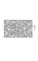
- FIG. 2 is a schematic cross-sectional view showing, in an enlarged manner, the microstructure of the decomposition product at the end of the first dehydrogenation recombination step in the method for producing a rare earth alloy powder according to the present embodiment.
- Such a fine structure can be confirmed by observing the cross section of the decomposition product with a scanning electron microscope.
- the rare earth alloy powder (decomposition product) is mainly composed of a rare earth hydride phase 10, an iron compound phase 20 such as ⁇ -Fe and Fe 2 B, and an R 2 Fe 14 B phase. 30 and the rare earth hydride phase 10 is covered with the R 2 Fe 14 B phase 30.
- the area ratio of the R 2 Fe 14 B phase is 25 to 55%, preferably 28 to 43%, more preferably 30 to 40%, based on the entire cross-sectional area.
- the time from the start to the end of nucleation of the R 2 Fe 14 B phase 30 is shortened as much as possible to increase the time during which the grain growth of the R 2 Fe 14 B phase 30 proceeds slowly, and
- the area ratio of the R 2 Fe 14 B phase is set to the above numerical range, it is possible to suppress the R 2 Fe 14 B phase 30 from finally becoming coarse particles.
- fine particles of the R 2 Fe 14 B phase 30 are formed, a rare earth alloy powder having an excellent coercive force can be obtained.
- the area ratio of the R 2 Fe 14 B phase 30 based on the entire area of the cross section in the cross section of the decomposition product can be calculated by the following method.
- the decomposition product is embedded in a resin, a mirror sample is prepared by sandpaper and buffing, and a reflected electron image of the sample is observed with a scanning electron microscope (SEM, magnification: 20,000).
- SEM scanning electron microscope
- the area of about 4.5 ⁇ m ⁇ 6.0 ⁇ m is observed by two visual fields, and the areas of the rare earth hydride phase 10, the iron compound phase 20 such as ⁇ -Fe and Fe 2 B, and the R 2 Fe 14 B phase 30 are respectively determined.
- the area ratio of the R 2 Fe 14 B phase can be determined by image analysis processing based on the entire cross-sectional area.
- the rare earth hydride phase is covered with the R 2 Fe 14 B phase in the cross section of the decomposition product, and R 2
- the area ratio of the Fe 14 B phase is 25 to 55% based on the entire cross-sectional area.
- the decomposition in the first dehydrogenation recombination step is performed by making the rate of decrease in the hydrogen partial pressure in the first dehydrogenation recombination step larger than the rate of decrease in the hydrogen partial pressure in the second dehydrogenation recombination step.
- the hydrogen release rate from the product is larger than that in the second dehydrogenation recombination step.
- the temperature (T 2 ) of the first dehydrogenation recombination step is higher than the temperature (T 1 ) of the hydrocracking step, the decomposition product from the decomposition product in the first dehydrogenation recombination step. Hydrogen release rate can be increased. As a result, the nucleation in the rare earth alloy becomes finer and more uniform than in the past, and it is considered that segregation can be prevented from being precipitated in the grains during the nucleation.
- the rare earth alloy powder obtained by the method for producing a rare earth alloy powder of the present embodiment has a refined R 2 Fe 14 B phase, it can be suitably used as an alloy powder for a rare earth magnet. That is, if a magnet is produced using the rare earth alloy powder obtained by the above production method, a magnet having excellent magnetic properties (particularly coercive force) can be obtained.
- the rare earth alloy powder is preferably a magnet powder having magnetic anisotropy.
- it can be suitably used as a raw material for anisotropic bonded magnets and sintered magnets having excellent magnetic properties.
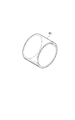
- FIG. 3 is a perspective view showing the anisotropic bonded magnet according to the present embodiment.
- An anisotropic bonded magnet 50 shown in FIG. 3 includes a resin and an anisotropic magnet powder bonded by the resin.
- the anisotropic magnet powder the rare earth alloy powder described above can be used.
- the resin include thermosetting resins such as epoxy resins and phenol resins, styrene-based, olefin-based, urethane-based, polyester-based, polyamide-based elastomers, ionomers, ethylene-propylene copolymers (EPM), and ethylene-ethyl acrylate.
- thermoplastic resins such as polymers.
- a thermosetting resin is preferable and an epoxy resin or a phenol resin is more preferable.
- the anisotropic bonded magnet 50 of this embodiment has excellent magnetic properties because anisotropic magnet powder is oriented in a specific direction.
- the content ratio of the magnet powder and the resin in the anisotropic bonded magnet 50 preferably includes 0.5 to 20 parts by mass of the resin with respect to 100 parts by mass of the magnet powder. If the resin content is less than 0.5 parts by mass with respect to 100 parts by mass of the magnet powder, shape retention tends to be impaired. If the resin exceeds 20 parts by mass, sufficiently excellent magnetic properties are obtained. It tends to be difficult to obtain.
- Such an anisotropic bonded magnet can be manufactured by a usual method. An example of the manufacturing method will be described below. First, the resin binder containing the above-mentioned resin and magnet powder are kneaded with a pressure kneader (pressure kneader) to prepare a compound (composition) for an anisotropic bonded magnet containing the resin binder and magnet powder. A coupling agent and other additives may be added to the anisotropic bonded magnet compound as necessary.
- An anisotropic bonded magnet can be obtained by preparing a compound for the above-mentioned anisotropic bonded magnet and then performing a molding process in which the compound is compressed and molded in a magnetic field.
- the compression molding can be performed using a compression molding machine such as a mechanical press or a hydraulic press.
- a compression molding machine such as a mechanical press or a hydraulic press.
- This anisotropic bonded magnet has excellent magnetic properties because the particles of the R 2 Fe 14 B phase 30 contain fine anisotropic magnet powder and the magnet powder is oriented in a specific direction. Have.
- an anisotropic bonded magnet is not limited to the method by the above-mentioned compression molding, For example, you may shape
- the anisotropic bonded magnet compound is heated to the melting temperature of the binder (thermoplastic resin) as necessary to obtain a fluid state, and then the compound has a predetermined shape and a magnetic field is applied. Injection into a mold and molding in a magnetic field. Then, it cools and takes out the molded article (anisotropic bond magnet) which has a predetermined shape from a metal mold
- FIG. 4 is a perspective view schematically showing the sintered magnet 60 according to the present embodiment.
- the sintered magnet 60 shown in FIG. 4 consists of a sintered body containing anisotropic magnet powder.
- anisotropic magnet powder the rare earth alloy powder described above can be used.
- the sintered magnet 60 of this embodiment has excellent magnetic properties because anisotropic magnet powder is oriented in a specific direction.
- Such a sintered magnet 60 can be manufactured by a normal method. An example of the manufacturing method will be described below.
- the above-mentioned anisotropic magnet powder is compressed and molded in a magnetic field to produce a molded body.
- the compression molding can be performed using a compression molding machine such as a mechanical press or a hydraulic press.
- the applied magnetic field strength is preferably 800 kA / m or more, and the molding pressure is preferably about 100 to 500 MPa.
- an appropriate amount of a binder for example, PVA
- the prepared molded body is sintered at 1000 to 1200 ° C.
- the sintering atmosphere is preferably an inert gas atmosphere such as argon gas.
- an aging treatment may be performed by heating the sintered body at 400 to 900 ° C., preferably 450 to 700 ° C. for 1 to 5 hours in an inert gas atmosphere.
- This sintered magnet has excellent magnetic properties because the particles of the R 2 Fe 14 B phase 30 contain fine anisotropic magnet powder and the magnet powder is oriented in a specific direction.
- the manufacturing method of a sintered magnet is not limited to the above-mentioned method.
- the anisotropic bonded magnet is not limited to the above-described shape, and is an anisotropic bonded magnet having a desired shape (for example, a columnar shape, a flat plate shape, or a C-shaped shape) by changing a mold. be able to.
- Example 1 An Nd 2 Fe 14 B raw material alloy having the following composition was prepared by a strip casting method.
- Nd 28.00 mass% Fe: 70.01 mass%
- B 1.08 mass%
- Ga 0.36% by mass
- Nb 0.30 mass%
- This raw material alloy contained a small amount of inevitable impurities (0.2 to 0.3% by mass of the whole raw material alloy) in addition to the above-described elements.
- This raw material alloy was kept in a temperature range of 1000 to 1200 ° C. for 24 hours in a vacuum (homogenization heat treatment step).
- the Nd 2 Fe 14 B raw material alloy after the homogenization heat treatment was pulverized using a stamp mill and sieved to obtain a raw material alloy in powder form (particle size 1 to 2 mm).
- This raw material alloy was filled in a molybdenum-made container, loaded into a tubular heat treatment furnace having an infrared heating method, and subjected to a treatment by hydrocracking / dehydrogenation recombination (HDDR treatment) under the following conditions.
- the time chart of the said process was as showing in FIG.
- hydrogen gas is introduced into a tubular heat treatment furnace, and a hydrogen occlusion process (I in FIG. 1) holds the raw material alloy powder for 2 hours under the hydrogen gas atmosphere under the conditions of a hydrogen partial pressure of 100 kPa and a temperature (T 0 ) of 100 ° C. )
- a hydrogen occlusion process (I in FIG. 1) holds the raw material alloy powder for 2 hours under the hydrogen gas atmosphere under the conditions of a hydrogen partial pressure of 100 kPa and a temperature (T 0 ) of 100 ° C. )
- T 0 a temperature
- a retained hydrocracking step was performed (II in FIG. 1).
- the hydrogen storage alloy was hydrocracked to obtain a cracked product.
- hydrogen is released from the decomposition product at a hydrogen release rate a of 3.5% by mass / hour, based on the mass of the entire decomposition product before releasing hydrogen.
- the hydrogen concentration in the decomposition product was reduced to a hydrogen concentration ⁇ 2 (0.230% by mass).
- the hydrogen gas exhaust rate from the inside of the furnace is changed so that the dropping rate of the furnace pressure (hydrogen partial pressure) is 0.1 kPa / min. .
- the hydrogen release rate b from the decomposition product was adjusted to 0.35% by mass / hour based on the mass of the entire decomposition product before releasing hydrogen.
- the hydrogen partial pressure (exhaust speed switching pressure) when the hydrogen release speed a was changed to the hydrogen release speed b was 6 kPa.
- the time required for the first dehydrogenation recombination step was about 2 minutes, and the time required for the second dehydrogenation recombination step was 40 to 50 minutes.
- Nd 2 Fe 14 B powder was pulverized using a mortar in an inert atmosphere and sieved to obtain Nd 2 Fe 14 B powder having a particle size of 53 to 212 ⁇ m.
- the powder and paraffin were packed in a case, and a magnetic powder of 1 Tesla was applied in a state where the paraffin was melted to orient the magnet powder.
- a magnetic field was obtained by applying a pulse magnetic field of 6 Tesla in a direction parallel to the orientation direction of the magnet powder and measuring a magnetization-magnetic field curve using a vibrating sample magnetometer (VSM).
- VSM vibrating sample magnetometer
- Table 1 shows the measurement results of residual magnetic flux density (Br) and coercive force (Hcj).
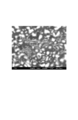
- FIG. 5 shows the result of observing the cross section of the primary particles of the Nd 2 Fe 14 B powder at the end of the first dehydrogenation recombination step using the backscattered electron image of the SEM using this observation sample.
- FIG. 5 is a cross-sectional SEM photograph of the decomposition product at the end of the first dehydrogenation recombination step in the rare earth alloy powder manufacturing step according to Example 1.
- the Nd hydride phase (white part in the figure) was covered with the Nd 2 Fe 14 B phase (light gray part in the figure) as shown in FIG. It was.
- the area ratio of the Nd 2 Fe 14 B phase based on the entire cross-sectional area was 33.7% (see Table 1).
- FIG. 6 shows the observation sample prepared under the conditions of Example 1 except that the pressure in the furnace (partial hydrogen pressure) was reduced at a rate of 4 kPa / min in the first dehydrogenation recombination step. It is sectional drawing of the decomposition product at the time of completion
- Nd hydride phase is observed to have been covered by Nd 2 Fe 14 B phase, when relative to the whole area of the cross section, the area ratio of the Nd 2 Fe 14 B phase is 78 It was 6%.
- the Nd 2 Fe 14 B phase grows into coarse grains after the second dehydrogenation recombination step, it is difficult to obtain a rare earth alloy powder having a refined Nd 2 Fe 14 B phase.
- Examples 2-5 and Comparative Examples 1-2 Values shown in Table 1 for exhaust speed switching pressure (hydrogen partial pressure) when switching from the first dehydrogenation recombination process to the second dehydrogenation recombination process (changing from hydrogen release speed a to hydrogen release speed b)
- An anisotropic Nd 2 Fe 14 B powder was obtained in the same manner as in Example 1, except that it was changed to. Then, in the same manner as in Example 1, the magnetic characteristics and the microstructure were evaluated.
- the Nd hydride phase was covered with the Nd 2 Fe 14 B phase, but in Comparative Example 2, a part of the Nd hydride phase was covered with the Nd 2 Fe 14 B phase. It wasn't.
- Table 1 summarizes HDDR processing conditions and evaluation results of Examples 2 to 5 and Comparative Examples 1 and 2.
- Example 6 In the second dehydrogenation recombination step, anisotropic Nd 2 Fe 14 B powder was obtained in the same manner as in Example 1 except that the hydrogen release rate b was changed as follows. Then, in the same manner as in Example 1, the magnetic characteristics and the microstructure were evaluated. In any of the examples, the Nd hydride phase was covered with the Nd 2 Fe 14 B phase. Table 2 summarizes the HDDR processing conditions and evaluation results of Examples 6 to 8.
- Example 6 After hydrogen release rate b was adjusted to 0.1% by mass / hour to release hydrogen for 25 minutes (hydrogen release rate b 1 ), hydrogen release rate b was adjusted to 3.5% by mass / hour (hydrogen Release rate b 2 ).
- Example 7 After maintaining the hydrogen release rate b at 0 mass% / hour for 60 minutes without releasing hydrogen (hydrogen release rate b 1 ), the hydrogen release rate b was adjusted to 0.35 mass percent / hour (hydrogen Release rate b 2 ). Thereafter, hydrogen was continuously released until the pressure in the furnace became less than 1 Pa, whereby hydrogen was almost completely removed from the decomposition product. The time required for the second dehydrogenation recombination step was 100 to 110 minutes.
- Example 8 After hydrogen release rate b was adjusted to 0.4 mass% / hour to release hydrogen for 25 minutes (hydrogen release rate b 1 ), hydrogen release rate b was adjusted to 0.18 mass% / hour (hydrogen Release rate b 2 ). Thereafter, hydrogen was continuously released until the pressure in the furnace became less than 1 Pa, whereby hydrogen was almost completely removed from the decomposition product. The time required for the second dehydrogenation recombination step was 65 to 75 minutes.
Landscapes
- Chemical & Material Sciences (AREA)
- Engineering & Computer Science (AREA)
- Mechanical Engineering (AREA)
- Materials Engineering (AREA)
- Metallurgy (AREA)
- Organic Chemistry (AREA)
- Power Engineering (AREA)
- Inorganic Chemistry (AREA)
- Crystallography & Structural Chemistry (AREA)
- Manufacturing & Machinery (AREA)
- Hard Magnetic Materials (AREA)
- Powder Metallurgy (AREA)
- Manufacturing Cores, Coils, And Magnets (AREA)
Abstract
(a)希土類元素を含有する原料合金を水素化分解させて分解生成物を得る工程と、(b)分解生成物から水素を放出させて分解生成物の水素濃度を低減する工程と、(c)工程(b)における水素の放出速度よりも低い放出速度で分解生成物から水素を更に放出させて希土類合金粉末を得る工程と、を備え、分解生成物の断面において、R2Fe14B相(Rは希土類元素を示す。)が希土類水素化物相を覆っており、R2Fe14B相の面積割合が上記断面の面積全体を基準として、25~55%となる時点で、工程(b)から工程(c)に移行することを特徴とする水素化分解・脱水素再結合法による希土類合金粉末の製造方法。
Description
本発明は、希土類合金粉末の製造方法、並びに異方性ボンド磁石及び焼結磁石に関する。
磁石用の合金粉末を製造する方法として、HDDR法(水素化分解・脱水素再結合法)が知られている。HDDR法とは、水素化(Hydrogenation)、不均化(Disproportionation)、脱水素化(Desorption)、及び再結合(Recombination)を順次実行するプロセスである。
このHDDR法は、固相-気相反応を伴う方法であるため、その反応機構が複雑であり、製造条件によって、得られる磁石粉末の保磁力などの磁気特性が変動する。このため、HDDR法を用いた磁石粉末の製造において、製造条件を調整することによって磁石粉末の磁気特性を改善することが試みられている。例えば、特許文献1では、脱水素再結合の処理中に、雰囲気を制御することによって反応速度を変えて磁石粉末の磁気特性を改善することが提案されている。
しかしながら、上記特許文献1のように雰囲気を制御しても、十分に高い保磁力を得ることは困難である。このため、HDDR法を用いて優れた磁気特性を有する希土類合金粉末を製造する方法を確立することが求められている。
本発明は上記事情に鑑みてなされたものであり、HDDR法を改良した方法であって、優れた磁気特性を有する希土類合金粉末を製造可能な方法を提供することを目的とする。また、上記方法によって製造された希土類合金粉末を含む異方性ボンド磁石及び焼結磁石を提供することを目的とする。
本発明に係る希土類合金粉末の製造方法は、水素化分解・脱水素再結合法による希土類合金粉末の製造方法であって、
(a)希土類元素を含有する原料合金を水素化分解させて分解生成物を得る工程と、
(b)分解生成物から水素を放出させて分解生成物の水素濃度を低減する工程と、
(c)工程(b)における水素の放出速度よりも低い放出速度で分解生成物から水素を更に放出させて希土類合金粉末を得る工程と、
を備え、分解生成物の断面において、R2Fe14B相(Rは希土類元素を示す。)が希土類水素化物相を覆っており、R2Fe14B相の面積割合が上記断面の面積全体を基準として、25~55%となる時点で、工程(b)から工程(c)に移行することを特徴とする。
(a)希土類元素を含有する原料合金を水素化分解させて分解生成物を得る工程と、
(b)分解生成物から水素を放出させて分解生成物の水素濃度を低減する工程と、
(c)工程(b)における水素の放出速度よりも低い放出速度で分解生成物から水素を更に放出させて希土類合金粉末を得る工程と、
を備え、分解生成物の断面において、R2Fe14B相(Rは希土類元素を示す。)が希土類水素化物相を覆っており、R2Fe14B相の面積割合が上記断面の面積全体を基準として、25~55%となる時点で、工程(b)から工程(c)に移行することを特徴とする。
上記方法は、水素化分解・脱水素再結合法を改良した方法であり、優れた磁気特性を有する希土類合金粉末を製造することができる。このような希土類合金粉末が得られる主な要因としては、工程(c)における水素の放出速度を、工程(b)における水素の放出速度よりも小さくしていること、及び工程(b)から工程(c)に移行するタイミングを、R2Fe14B相の粒成長の程度により規定していることが考えられる。つまり、工程(a)で得られた分解生成物に対する脱水素再結合処理を工程(b)及び工程(c)で実施することで、分解生成物中に生成したR2Fe14B相の核が粗大粒へと成長することを抑制でき、微細化したR2Fe14B相を有する希土類合金粉末が得られるものと考えられる。
本発明の製造方法は、上記断面のモルフォロジーを観察することにより、工程(b)から工程(c)に移行するタイミングを決定する工程を更に備えたものであってもよい。当該工程を実施することで、例えば、新たな組成の希土類合金粉末を製造する場合や製造条件を変更した場合であっても、微細化したR2Fe14B相を有する希土類合金粉末を安定的に作製できる。
また、本発明は、上記の製造方法によって製造された異方性を有する希土類合金粉末と、樹脂とを含む異方性ボンド磁石を提供する。本発明の異方性ボンド磁石は、優れた磁気特性を有する異方性の希土類合金粉末を含んでいるため、優れた磁気特性を有する。
更に、本発明は、上記の製造方法によって製造された異方性を有する希土類合金粉末の成形体を焼結して得られる焼結磁石を提供する。本発明の焼結磁石は、優れた磁気特性を有する異方性の希土類合金粉末を含んでいため、優れた磁気特性を有する。
本発明によれば、優れた磁気特性を有する希土類合金粉末を製造することができ、また、優れた磁気特性を有する異方性ボンド磁石及び焼結磁石を提供できる。
<希土類合金粉末の製造方法>
本実施形態の希土類合金粉末の製造方法は、いわゆる水素化分解・脱水素再結合法(HDDR法)による希土類合金粉末の製造方法である。この製造方法は、希土類元素の含有量がρ(質量%)である原料合金を準備し、当該合金を、水素雰囲気中、温度T0で所定時間保持する水素吸蔵工程と、温度T0よりも高い温度T1で水素化分解させて水素濃度η1(質量%)の分解生成物を得る水素化分解工程(工程(a))と、温度T1から温度T1よりも高い温度T2に昇温する昇温工程と、温度T2で、分解生成物から水素を所定の速度で放出させて、分解生成物の水素濃度をη1(質量%)からη2(質量%)まで低減する第1の脱水素再結合工程(工程(b))と、第1の脱水素再結合工程よりも分解生成物からの水素の放出速度を低くして、分解生成物の水素濃度ηをさらに低減し、水素を実質的に含まない希土類合金粉末を得る第2の脱水素再結合工程(工程(c))と、希土類合金粉末を室温にまで冷却する冷却工程とを有する。
本実施形態の希土類合金粉末の製造方法は、いわゆる水素化分解・脱水素再結合法(HDDR法)による希土類合金粉末の製造方法である。この製造方法は、希土類元素の含有量がρ(質量%)である原料合金を準備し、当該合金を、水素雰囲気中、温度T0で所定時間保持する水素吸蔵工程と、温度T0よりも高い温度T1で水素化分解させて水素濃度η1(質量%)の分解生成物を得る水素化分解工程(工程(a))と、温度T1から温度T1よりも高い温度T2に昇温する昇温工程と、温度T2で、分解生成物から水素を所定の速度で放出させて、分解生成物の水素濃度をη1(質量%)からη2(質量%)まで低減する第1の脱水素再結合工程(工程(b))と、第1の脱水素再結合工程よりも分解生成物からの水素の放出速度を低くして、分解生成物の水素濃度ηをさらに低減し、水素を実質的に含まない希土類合金粉末を得る第2の脱水素再結合工程(工程(c))と、希土類合金粉末を室温にまで冷却する冷却工程とを有する。
図1は、本実施形態に係る希土類合金粉末の製造方法のタイムチャートである。図1の(a)は、温度のタイムチャートであり、図1の(b)は、原料合金、分解生成物及び希土類合金粉末の水素濃度のタイムチャートである。以下、図1を適宜参照しながら本実施形態の製造方法を説明する。
水素吸蔵工程(図1中のI)は、希土類元素の含有量がρ(質量%)である原料合金を、水素雰囲気中、温度T0で所定時間保持して、原料合金に水素を吸蔵させる工程である。原料合金としては、R2Fe14Bで表されるR-Fe-B系合金を用いることができる。一層優れた磁気特性を有する希土類合金粉末を得る観点から、R-Fe-B系合金の組成は、R:25~35質量%、B:1~1.6質量%、Fe:63.4~74質量%であることが好ましい。Rとしては、Y、La、Ce、Pr、Nd、Sm、Gd、Td、Dy、Ho、Er、Tm、Luから選ばれる1種または2種以上とすることができる。このうち、製造コスト及び磁気特性の観点から、RはNdを含むことが好ましい。
希土類金属における質量基準のRの含有量ρ(質量%)は、用いられる希土類金属の種類にもよるが、好ましくは25~35質量%、より好ましくは27~33質量%である。
上述の原料合金は、通常の鋳造方法、例えばストリップキャスト法、ブックモールド法、又は遠心鋳造法によって調製することができる。原料合金には、均質化熱処理を施してもよい。また、原料合金は、不純物を含んでいてもよい。
均質化熱処理は、原料合金を、真空又はアルゴンや窒素などの不活性ガス雰囲気中、温度1000~1200℃で5~48時間保持することによって行う。このような均質化熱処理を行うことによって、原料合金を融解させて、原料合金を均質化させることができる。
均質化させた原料合金は、スタンプミル又はジョークラッシャーなどの粉砕手段を用いて粉砕した後、篩分けすることが好ましい。これによって、粒径が10mm以下の粉末状の原料合金を調製することができる。
水素吸蔵工程では、上述の粉末状の原料合金を、水素分圧が100~300kPaである水素雰囲気中、温度T0で時間t1まで保持する。これによって、原料合金の結晶格子中に水素が吸蔵されて、水素濃度η0(質量%)の水素吸蔵合金を得ることができる。水素濃度η0は、例えば、0.3~0.5質量%の範囲とする。なお、この段階では、原料合金は分解していない。
水素吸蔵工程における温度T0は、100~200℃であることが好ましい。また、水素吸蔵工程の所要時間t1は、0.5~2時間であることが好ましい。
水素化分解工程(図1中のII)では、水素吸蔵合金を、水素雰囲気中、温度T0よりも高い温度T1で保持することによって、水素化分解させて、水素濃度η1(質量%)の分解生成物を得る。
水素化分解工程における雰囲気の水素分圧は10~100kPa、温度T1は700~850℃であることが好ましい。この条件で水素吸蔵合金の水素化分解を行うことによって、磁気的な異方性を有する希土類合金粉末を得ることができる。水素分圧が10kPa未満であると、水素化分解が十分に進行しない傾向があり、100kPaを超えると異方性の希土類合金粉末が得難くなる傾向がある。
温度T1が700℃未満であると、原料合金の水素化分解が十分に進行しない傾向がある。一方、温度T1が850℃を超えると、所望の分解生成物(水素化物)が得られ難くなる傾向がある。
水素化分解工程の所要時間(図1中のt2-t1)は、0.5~60時間であることが好ましい。この時間が0.5時間未満であると、原料合金の水素化分解が十分に進行しない傾向があり、60時間を超えると磁気的な異方性を有する希土類合金粉末が得られ難くなる傾向がある。
水素化分解工程で得られる分解生成物は、RHXなどの水素化物、α-Fe及びFe2Bなどの鉄化合物を含んでいる。この段階における分解生成物は、100nmオーダーの微細なマトリックスを形成している。
上述の分解生成物の水素濃度η1(質量%)の上限は、通常、含まれる希土類元素が全て水素化物(RHX,x=2~3)となる濃度である。水素濃度η1(質量%)は、希土類元素の種類にもよるが、例えば0.35~0.6質量%の範囲となる。
昇温工程(図1中のIII)では、分解生成物の温度を温度T1から温度T1よりも高い温度T2に昇温する。温度T2は、温度T1よりも高く、720~950℃であることが好ましく、750~950℃であることがより好ましい。なお、昇温速度に特に制限はない。昇温工程の所要時間(図1中のt3-t2)は、例えば1~10分間である。
第1の脱水素再結合工程(図1中のIV)では、温度T1よりも高い温度T2で、分解生成物から水素を所定の放出速度で放出させて、分解生成物の水素濃度を、η1(質量%)からη2(質量%)まで低減させる。この工程によって、水素化分解工程で得られた分解生成物のマトリックス中に希土類合金の核が生成すると考えられる。
水素濃度η1(質量%)である分解生成物からの水素の放出速度は、水素を放出させる前の分解生成物全体の質量を基準として、0.75~30質量%/時であることが好ましい。これによって、希土類合金の核をより均一に生成させることができる。また、分解生成物の水素濃度ηが、0.1~0.35質量%の範囲、好ましくは0.2~0.3質量%の範囲となるまで水素を放出させる。これによって、希土類合金の核をより均一に生成させることができる。なお、分解生成物の水素濃度η2(質量%)は、分解生成物の質量を計測することによって知ることができる。
分解生成物からの水素の放出速度は、雰囲気中の水素分圧の降下速度を制御することによって調整することができる。つまり、水素分圧の降下速度を大きくすれば、分解生成物からの水素の放出速度を大きくすることができる。水素分圧の降下速度は、例えばアルゴンガスを導入したり、減圧したりすることによって、調整することができる。第1の脱水素再結合工程における水素分圧の降下速度は、10~40kPa/分とすることが好ましく、12~20kPa/分とすることがより好ましい。
第1の脱水素再結合工程における分解生成物の温度T2は、温度T1よりも高く、720~950℃に保つことが好ましく、750~950℃に保つことがより好ましい。分解生成物の温度T2を、温度T1よりも高くすることによって、分解生成物から水素が抜けやすくなり、希土類合金の核をより均一に生成させることができる。温度T2と温度T1との温度差は、20℃以上であってもよく、100℃以上であってもよい。該温度差を100℃以上にすることによって、粒子のサイズの均一性を維持しつつ偏析物の個数を一層低減することができる。
温度T2が750℃未満であると、分解生成物からの水素の放出速度を十分に大きくすることができず、希土類合金の核生成が不均一になる傾向がある。一方、温度T2が950℃を超えると、分解生成物からの水素の放出速度が大きくなりすぎるために、分解生成物の水素濃度ηを制御することが難しくなる傾向がある。
第1の脱水素再結合工程の時間(図1中のt4-t3)は、例えば0.01~0.5時間である。なお、この時間は、分解生成物からの水素の放出速度に依存する。
第2の脱水素再結合工程(図1中のV)では、第1の脱水素再結合工程よりも分解生成物からの水素の放出速度を小さくして、分解生成物の水素濃度をさらに低減し、雰囲気中の水素分圧を1Pa未満にまで下げて希土類合金粉末を得る。
第2の脱水素再結合工程の温度は、第1の脱水素再結合工程における温度T2と同じにすることが好ましい。これによって、分解生成物からの水素の放出を円滑に進行させることができる。
水素濃度η2(質量%)である分解生成物からの水素の放出速度、すなわち分解生成物の水素濃度ηの降下速度は、水素を放出させる前(第1の脱水素再結合工程の開始前)の分解生成物全体の質量を基準として、0.01~0.4質量%/時とすることが好ましい。これによって、分解生成物中に析出した希土類合金の核の成長が徐々に進行することとなり、希土類合金の粒内に偏析物が残留することを抑制することができる。水素濃度ηの降下速度が0.4質量%を超えると、分解生成物に含まれるα-Feや鉄リッチ相が再結合できずに希土類合金の粒内に取り残されやすくなる傾向がある。一方、水素濃度ηの降下速度が0.01質量%未満であると、工程に所要する時間が長くなり過ぎて再結合した希土類合金の異常粒成長が起こりやすくなる傾向がある。
偏析物としては、α-Feや、鉄リッチな化合物、及び原料合金に含まれるNbなどの不純物に由来する化合物等が挙げられる。このような偏析物が希土類合金粉末の一次粒子の粒内に存在すると、逆磁区が発生して高い保磁力が得られ難くなる。
なお、第2の脱水素再結合工程では、最終的に分解生成物から水素をほぼ完全に除去できればよく、放出速度を二段階以上に分けて行う等、分解生成物から水素を一定の放出速度で放出させなくてもよい。例えば、放出速度を二段階に分けて行う場合、希土類合金の核生成の開始直後は温度が不安定になりやすいので、再結合反応を一旦止めるか、再結合反応をなるべく緩やかに進行させるという観点から、一段階目の放出速度は0~0.4質量%/時であることが好ましく、0~0.1質量%/時であることがより好ましい。また、希土類合金の核生成開始から一定の時間が経過すれば温度は安定しやすくなるので、再結合反応を一段階目よりも速く進行させることができるという観点から、二段階目の放出速度は0.1~4質量%/時であることが好ましく、0.1~0.4質量%/時であることがより好ましい。
なお、一段階目から二段階目への放出速度の切り替えは、温度が安定してから行うことが好ましく、第2の脱水素再結合工程開始後、15分以上であることが好ましく、60分以上であることがより好ましい。
第2の脱水素再結合工程の時間(図1中のt5-t4)は、例えば0.3~5時間とすることができる。この時間は、分解生成物からの水素の放出速度に依存する。なお、第2の脱水素再結合工程における水素分圧の降下速度は、0.01~0.2kPa/分とすることが好ましい。
最後に、冷却工程により、第2の脱水素再結合工程で得られた希土類合金粉末を室温にまで冷却する(図1中のVI)。以上の工程によって、一次粒子の粒内の偏析物が十分に低減された異方性の希土類合金粉末を得ることができる。この希土類合金粉末は、通常原料合金と同じ組成を有する。
本実施形態の希土類合金粉末の製造方法は、脱水素再結合処理がなされている分解生成物の断面を拡大して観察することにより、第1の脱水素再結合工程から第2の脱水素再結合工程に移行するタイミングを決定する工程をさらに有していてもよい。当該工程により、第1及び第2の脱水素再結合工程における水素の放出速度を決定してもよい。当該工程を実施することで、例えば、新たな組成の希土類合金粉末を製造する場合や製造条件を変更した場合であっても、微細化したR2Fe14B相を有する希土類合金粉末を安定的に作製できる。この工程では、第1の脱水素再結合工程における分解生成物の断面を、例えば、SEMで表面分析して、モルフォロジーを観察する。
図2は、本実施形態に係る希土類合金粉末の製造方法における、第1の脱水素再結合工程終了時点での分解生成物の微細構造を拡大して示す模式断面図である。このような微細構造は、分解生成物の断面を走査型電子顕微鏡で観察することによって確認することができる。
第1の脱水素再結合工程終了時点では、希土類合金粉末(分解生成物)は、主として希土類水素化物相10、α-Fe及びFe2Bなどの鉄化合物相20、及びR2Fe14B相30から構成されており、希土類水素化物相10がR2Fe14B相30により覆われている。このとき、R2Fe14B相の面積割合は、断面の面積全体を基準として、25~55%であるが、好ましくは28~43%であり、より好ましくは30~40%である。すなわち、脱水素再結合工程において、R2Fe14B相30の核生成開始から終了までの時間をなるべく短くしてR2Fe14B相30の粒成長が緩やかに進行する時間を増やし、かつR2Fe14B相の面積割合を上記の数値範囲とすることで、最終的にR2Fe14B相30が粗大粒となることを抑制できる。これにより、R2Fe14B相30の微細な粒子が形成されることになるため、優れた保磁力を有する希土類合金粉末を得ることが可能となる。
分解生成物の断面における、断面の面積全体を基準としたR2Fe14B相30の面積割合は、以下の方法によって算出することができる。分解生成物を樹脂に埋め込み、サンドペーパーおよびバフによる研磨で鏡面サンプルを作製し、走査型電子顕微鏡(SEM、倍率:20,000)でそのサンプルの反射電子像を観察する。約4.5μm×6.0μmの領域を2視野ずつ観察して、希土類水素化物相10、α-Fe及びFe2Bなどの鉄化合物相20、及びR2Fe14B相30それぞれの面積を、コントラストの違いを基にして画像解析処理により算出し、断面の面積全体を基準としたR2Fe14B相の面積割合を求めることができる。
本実施形態の希土類合金粉末の製造方法では、第1の脱水素再結合工程終了時点で、分解生成物の断面において、希土類水素化物相がR2Fe14B相により覆われており、R2Fe14B相の面積割合が、断面の面積全体を基準として、25~55%となっている。そして、第1の脱水素再結合工程における水素分圧の降下速度を第2の脱水素再結合工程の水素分圧の降下速度よりも大きくすることにより、第1の脱水素再結合工程における分解生成物からの水素放出速度を第2の脱水素再結合工程よりも大きくしている。また、第1の脱水素再結合工程の温度(T2)を、水素化分解工程の温度(T1)よりも高くしているため、第1の脱水素再結合工程において分解生成物からの水素放出速度を大きくすることができる。これによって、希土類合金における核生成が従来よりも微細で均一となり、また、核成長時において偏析物が粒内に析出するのを抑制することができると考えられる。
本実施形態の希土類合金粉末の製造方法によって得られる希土類合金粉末は、微細化したR2Fe14B相を有しているため、希土類磁石用の合金粉末として好適に用いることができる。すなわち、上記製造方法によって得られる希土類合金粉末を用いて磁石を作製すれば、磁気特性(特に保磁力)に優れる磁石を得ることができる。
この希土類合金粉末は、磁気的な異方性を有する磁石粉末であることが好ましい。これによって、磁気特性に優れる異方性ボンド磁石や焼結磁石の原料として好適に用いることができる。
<異方性ボンド磁石>
図3は、本実施形態に係る異方性ボンド磁石を示す斜視図である。図3に示す異方性ボンド磁石50は、樹脂と該樹脂によって結合された異方性磁石粉末とを含む。異方性磁石粉末としては、上述の希土類合金粉末を用いることができる。樹脂としては、エポキシ樹脂、フェノール樹脂等の熱硬化性樹脂や、スチレン系、オレフィン系、ウレタン系、ポリエステル系、ポリアミド系のエラストマー、アイオノマー、エチレンプロピレン共重合体(EPM)、エチレン-エチルアクリレート共重合体等の熱可塑性樹脂が挙げられる。なかでも、熱硬化性樹脂が好ましく、エポキシ樹脂又はフェノール樹脂がより好ましい。
図3は、本実施形態に係る異方性ボンド磁石を示す斜視図である。図3に示す異方性ボンド磁石50は、樹脂と該樹脂によって結合された異方性磁石粉末とを含む。異方性磁石粉末としては、上述の希土類合金粉末を用いることができる。樹脂としては、エポキシ樹脂、フェノール樹脂等の熱硬化性樹脂や、スチレン系、オレフィン系、ウレタン系、ポリエステル系、ポリアミド系のエラストマー、アイオノマー、エチレンプロピレン共重合体(EPM)、エチレン-エチルアクリレート共重合体等の熱可塑性樹脂が挙げられる。なかでも、熱硬化性樹脂が好ましく、エポキシ樹脂又はフェノール樹脂がより好ましい。
本実施形態の異方性ボンド磁石50は、異方性の磁石粉末が特定方向に配向しているため、優れた磁気特性を有する。異方性ボンド磁石50における磁石粉末と樹脂との含有比率は、磁石粉末100質量部に対して、樹脂を例えば0.5~20質量部含むことが好ましい。磁石粉末100質量部に対して、樹脂の含有量が0.5質量部未満であると、保形性が損なわれる傾向があり、樹脂が20質量部と超えると、十分に優れた磁気特性が得られ難くなる傾向がある。
このような異方性ボンド磁石は通常の方法で製造することができる。製造方法の一例について以下に説明する。まず、上述の樹脂を含む樹脂バインダーと磁石粉末とを加圧混練機(加圧ニーダー)で混練して樹脂バインダーと磁石粉末とを含む異方性ボンド磁石用コンパウンド(組成物)を調製する。異方性ボンド磁石用コンパウンドには、必要に応じて、カップリング剤やその他の添加材を加えてもよい。
上述の異方性ボンド磁石用コンパウンドを調製した後、このコンパウンドを圧縮して磁場中で成形する成形工程を行うことにより、異方性ボンド磁石を得ることができる。圧縮成形は、機械プレスや油圧プレス等の圧縮成形機を用いて行うことができる。このようにして、配向した異方性の磁石粉末と樹脂とを含む異方性ボンド磁石を得ることができる。この異方性ボンド磁石は、R2Fe14B相30の粒子が微細な異方性の磁石粉末を含有するとともに、当該磁石粉末が特定の方向に配向しているため、優れた磁気特性を有する。
なお、異方性ボンド磁石の製造方法は、上述の圧縮成形による方法に限定されるものではなく、例えば射出成形によって成形してもよい。この場合は、異方性ボンド磁石用コンパウンドを、必要に応じてバインダー(熱可塑性樹脂)の溶融温度まで加熱し、流動状態とした後、このコンパウンドを所定の形状を有し磁場が印加された金型内に射出して磁場中成形を行う。その後、冷却し、金型から所定形状を有する成形品(異方性ボンド磁石)を取り出す。このようにして異方性ボンド磁石を製造することができる。
<焼結磁石>
図4は、本実施形態に係る焼結磁石60を模式的に示す斜視図である。図4に示す焼結磁石60は、異方性磁石粉末を含む焼結体からなる。異方性磁石粉末としては、上述の希土類合金粉末を用いることができる。本実施形態の焼結磁石60は、異方性の磁石粉末が特定方向に配向しているため、優れた磁気特性を有する。
図4は、本実施形態に係る焼結磁石60を模式的に示す斜視図である。図4に示す焼結磁石60は、異方性磁石粉末を含む焼結体からなる。異方性磁石粉末としては、上述の希土類合金粉末を用いることができる。本実施形態の焼結磁石60は、異方性の磁石粉末が特定方向に配向しているため、優れた磁気特性を有する。
このような焼結磁石60は通常の方法で製造することができる。製造方法の一例について以下に説明する。まず、上述の異方性の磁石粉末を圧縮して磁場中で成形することにより成形体を作製する。圧縮成形は、機械プレスや油圧プレス等の圧縮成形機を用いて行うことができる。この場合、印加する磁場強度は800kA/m以上であると好ましく、成形圧力は100~500MPa程度であると好ましい。また、成形体の作製に際し、異方性の磁石粉末に、バインダ(例えば、PVA)を適量加えてもよい。次に、調製した成形体を、1000~1200℃で0.5~5時間程度焼結し、急冷して焼結体を作製する。焼結雰囲気は、アルゴンガス等の不活性ガス雰囲気であると好ましい。なお、必要に応じ、さらに不活性ガス雰囲気中で、400~900℃、好ましくは450~700℃で1~5時間、焼結体を加熱する時効処理を行ってもよい。このようにして、焼結磁石を得ることができる。この焼結磁石は、R2Fe14B相30の粒子が微細な異方性の磁石粉末を含有するとともに、当該磁石粉末が特定の方向に配向しているため、優れた磁気特性を有する。ただし、焼結磁石の製造方法は、上述の方法に限定されるものではない。
以上、本発明の好適な実施形態について説明したが、本発明は上記実施形態に何ら限定されるものではない。例えば、異方性ボンド磁石は、上述の形状に限定されるものではなく、金型を変えることによって所望の形状(例えば、柱状、平板状又はC型形状)を有する異方性ボンド磁石とすることができる。
本発明の内容を実施例及び比較例を用いて以下に詳細に説明するが、本発明は以下の実施例に限定されるものではない。
(実施例1)
ストリップキャスト法によって、以下の組成を有するNd2Fe14B原料合金を調製した。
ストリップキャスト法によって、以下の組成を有するNd2Fe14B原料合金を調製した。
Nd:28.00質量%
Fe:70.01質量%
B:1.08質量%
Ga:0.36質量%
Nb:0.30質量%
Fe:70.01質量%
B:1.08質量%
Ga:0.36質量%
Nb:0.30質量%
この原料合金は、上述の元素の他に、微量の不可避不純物(原料合金全体の0.2~0.3質量%)を含んでいた。この原料合金を、真空中、1000~1200℃の温度範囲で24時間保持した(均質化熱処理工程)。均質化熱処理後のNd2Fe14B原料合金を、スタンプミルを用いて粉砕し、篩分けを行って、粉末状(粒径1~2mm)の原料合金を得た。
この原料合金を、モリブテン製の容器に充填し、赤外線加熱方式を有する管状熱処理炉に装填し、以下の条件で水素化分解・脱水素再結合法による処理(HDDR処理)を施した。なお、当該処理のタイムチャートは図1に示すとおりであった。
まず、管状熱処理炉内に水素ガスを導入し、水素ガス雰囲気下、水素分圧100kPa、温度(T0)100℃の条件で原料合金粉末を2時間保持する水素吸蔵工程(図1中のI)を行った。これによって、原料合金に水素を吸蔵させて、水素吸蔵合金を得た。
続いて、炉内の水素分圧を下げるとともに炉内温度を10℃/秒で昇温し、水素吸蔵合金を、水素分圧40kPa、温度T1(=800℃)の条件で1.5時間保持する水素化分解工程を行った(図1中のII)。これによって、水素吸蔵合金を水素化分解させて分解生成物を得た。
その後、炉内温度を10℃/秒で温度T2(=850℃)まで昇温した(昇温工程、図1中のIII)。炉内温度をT2まで昇温した後、真空ポンプを用いて水素ガスを排気し、炉内の圧力(水素分圧)を16kPa/分の速度で下げることによって、分解生成物に含まれる水素の放出を開始した(第1の脱水素再結合工程、図1中のIV)。
第1の脱水素再結合工程では、分解生成物から、水素を放出させる前の分解生成物全体の質量を基準として、3.5質量%/時の水素放出速度aで水素を放出させて、分解生成物中の水素濃度を、水素濃度η2(0.230質量%)にまで低減した。
分解生成物中の水素濃度が水素濃度η2にまで下がったら、炉内からの水素ガスの排気速度を変更して、炉内圧力(水素分圧)の降下速度を0.1kPa/分とした。これによって、分解生成物からの水素放出速度bを、水素を放出させる前の分解生成物全体の質量を基準として0.35質量%/時に調整した。なお、水素放出速度aから水素放出速度bに変更したときの水素分圧(排気速度切り替え圧力)は、6kPaであった。その後、炉内の圧力(=水素分圧)が1Pa未満になるまで、水素の放出を継続して行うことにより、分解生成物から水素をほぼ完全に除去した(第2の脱水素再結合工程、図1中のV)。なお、第1の脱水素再結合工程に所要した時間は約2分間であり、第2の脱水素再結合工程に所要した時間は40~50分間であった。
炉内の圧力(水素分圧)が1Pa未満となった時点で、水素の放出を停止した。その後、炉内を室温(約20℃)まで冷却し、HDDR処理された異方性のNd2Fe14B粉末を得た。
[磁気特性の評価]
得られたNd2Fe14B粉末を、不活性雰囲気中で乳鉢を用いて粉砕し、篩い分けを行って、53~212μmの粒径を有するNd2Fe14B粉末とした。この粉末とパラフィンとをケースに詰めて、パラフィンを融解させた状態で1テスラの磁場を印加して磁石粉末を配向させた。磁石粉末の配向方向と平行な方向に6テスラのパルス磁場を印加し、振動試料型磁力計(VSM)を用いて磁化-磁場曲線を測定して磁気特性を求めた。残留磁束密度(Br)及び保磁力(Hcj)の測定結果を表1に示す。
得られたNd2Fe14B粉末を、不活性雰囲気中で乳鉢を用いて粉砕し、篩い分けを行って、53~212μmの粒径を有するNd2Fe14B粉末とした。この粉末とパラフィンとをケースに詰めて、パラフィンを融解させた状態で1テスラの磁場を印加して磁石粉末を配向させた。磁石粉末の配向方向と平行な方向に6テスラのパルス磁場を印加し、振動試料型磁力計(VSM)を用いて磁化-磁場曲線を測定して磁気特性を求めた。残留磁束密度(Br)及び保磁力(Hcj)の測定結果を表1に示す。
[微細構造の評価]
上記工程において、分解生成物中の水素濃度を、水素濃度η2(水素分圧6kPa)にまで低減し(図1中のIV)、その後、アルゴンガスを流して急冷させることにより反応を止め、観察用サンプルを作製した。この観察用サンプルを用い、第1の脱水素再結合工程終了時点でのNd2Fe14B粉末の一次粒子の断面をSEMの反射電子像を用いて観察した結果を図5に示す。図5は、実施例1に係る希土類合金粉末の製造工程における、第1の脱水素再結合工程終了時点での分解生成物の断面SEM写真である。観察は2視野において行ったが、いずれの視野においても、図5に示すとおりNd水素化物相(図中の白色部)はNd2Fe14B相(図中の薄い灰色部)により覆われていた。また、断面の面積全体を基準としたときの、Nd2Fe14B相の面積割合は33.7%(表1参照)であった。
上記工程において、分解生成物中の水素濃度を、水素濃度η2(水素分圧6kPa)にまで低減し(図1中のIV)、その後、アルゴンガスを流して急冷させることにより反応を止め、観察用サンプルを作製した。この観察用サンプルを用い、第1の脱水素再結合工程終了時点でのNd2Fe14B粉末の一次粒子の断面をSEMの反射電子像を用いて観察した結果を図5に示す。図5は、実施例1に係る希土類合金粉末の製造工程における、第1の脱水素再結合工程終了時点での分解生成物の断面SEM写真である。観察は2視野において行ったが、いずれの視野においても、図5に示すとおりNd水素化物相(図中の白色部)はNd2Fe14B相(図中の薄い灰色部)により覆われていた。また、断面の面積全体を基準としたときの、Nd2Fe14B相の面積割合は33.7%(表1参照)であった。
一方、実施例1との比較として、Nd2Fe14B相の粒成長が進んでしまっている場合の分解生成物の断面図を示す。図6は、第1の脱水素再結合工程において炉内の圧力(水素分圧)を4kPa/分の速度で下げたこと以外は、実施例1の条件にて観察サンプルを作製したときの、第1の脱水素再結合工程終了時点での分解生成物の断面図である。図6に示すとおり、Nd水素化物相がNd2Fe14B相により覆われているとは認められるものの、断面の面積全体を基準としたときの、Nd2Fe14B相の面積割合は78.6%であった。この場合、第2の脱水素再結合工程以降Nd2Fe14B相が粗大粒へと成長してしまうため、微細化したNd2Fe14B相を有する希土類合金粉末を得ることは難しい。
(実施例2~5及び比較例1~2)
第1の脱水素再結合工程から第2の脱水素再結合工程に切り替える(水素放出速度aから水素放出速度bに変更する)際の排気速度切り替え圧力(水素分圧)を表1に示す値に変更したこと以外は、実施例1と同様にして、異方性のNd2Fe14B粉末を得た。そして、実施例1と同様にして、磁気特性及び微細構造の評価を行った。いずれの実施例及び比較例1においても、Nd水素化物相はNd2Fe14B相により覆われていたが、比較例2においてはNd水素化物相の一部はNd2Fe14B相により覆われていなかった。実施例2~5及び比較例1~2のHDDR処理条件及び評価結果を表1に纏めて示す。
第1の脱水素再結合工程から第2の脱水素再結合工程に切り替える(水素放出速度aから水素放出速度bに変更する)際の排気速度切り替え圧力(水素分圧)を表1に示す値に変更したこと以外は、実施例1と同様にして、異方性のNd2Fe14B粉末を得た。そして、実施例1と同様にして、磁気特性及び微細構造の評価を行った。いずれの実施例及び比較例1においても、Nd水素化物相はNd2Fe14B相により覆われていたが、比較例2においてはNd水素化物相の一部はNd2Fe14B相により覆われていなかった。実施例2~5及び比較例1~2のHDDR処理条件及び評価結果を表1に纏めて示す。

(実施例6~8)
第2の脱水素再結合工程において、水素放出速度bを以下のように変更したこと以外は、実施例1と同様にして、異方性のNd2Fe14B粉末を得た。そして、実施例1と同様にして、磁気特性及び微細構造の評価を行った。いずれの実施例においても、Nd水素化物相はNd2Fe14B相により覆われていた。実施例6~8のHDDR処理条件及び評価結果を表2に纏めて示す。
実施例6:水素放出速度bを0.1質量%/時に調整して25分間水素を放出した後(水素放出速度b1)、水素放出速度bを3.5質量%/時に調整した(水素放出速度b2)。その後、炉内の圧力が1Pa未満になるまで、水素の放出を継続して行うことにより、分解生成物から水素をほぼ完全に除去した。なお、第2の脱水素再結合工程に所要した時間は35~40分間であった。
実施例7:水素放出速度bを0質量%/時として60分間水素を放出せずに保持した後(水素放出速度b1)、水素放出速度bを0.35質量%/時に調整した(水素放出速度b2)。その後、炉内の圧力が1Pa未満になるまで、水素の放出を継続して行うことにより、分解生成物から水素をほぼ完全に除去した。なお、第2の脱水素再結合工程に所要した時間は100~110分間であった。
実施例8:水素放出速度bを0.4質量%/時に調整して25分間水素を放出した後(水素放出速度b1)、水素放出速度bを0.18質量%/時に調整した(水素放出速度b2)。その後、炉内の圧力が1Pa未満になるまで、水素の放出を継続して行うことにより、分解生成物から水素をほぼ完全に除去した。なお、第2の脱水素再結合工程に所要した時間は65~75分間であった。
第2の脱水素再結合工程において、水素放出速度bを以下のように変更したこと以外は、実施例1と同様にして、異方性のNd2Fe14B粉末を得た。そして、実施例1と同様にして、磁気特性及び微細構造の評価を行った。いずれの実施例においても、Nd水素化物相はNd2Fe14B相により覆われていた。実施例6~8のHDDR処理条件及び評価結果を表2に纏めて示す。
実施例6:水素放出速度bを0.1質量%/時に調整して25分間水素を放出した後(水素放出速度b1)、水素放出速度bを3.5質量%/時に調整した(水素放出速度b2)。その後、炉内の圧力が1Pa未満になるまで、水素の放出を継続して行うことにより、分解生成物から水素をほぼ完全に除去した。なお、第2の脱水素再結合工程に所要した時間は35~40分間であった。
実施例7:水素放出速度bを0質量%/時として60分間水素を放出せずに保持した後(水素放出速度b1)、水素放出速度bを0.35質量%/時に調整した(水素放出速度b2)。その後、炉内の圧力が1Pa未満になるまで、水素の放出を継続して行うことにより、分解生成物から水素をほぼ完全に除去した。なお、第2の脱水素再結合工程に所要した時間は100~110分間であった。
実施例8:水素放出速度bを0.4質量%/時に調整して25分間水素を放出した後(水素放出速度b1)、水素放出速度bを0.18質量%/時に調整した(水素放出速度b2)。その後、炉内の圧力が1Pa未満になるまで、水素の放出を継続して行うことにより、分解生成物から水素をほぼ完全に除去した。なお、第2の脱水素再結合工程に所要した時間は65~75分間であった。

表1及び2の結果から、実施例1~8のNd2Fe14B粉末中に、R2Fe14B相の微細な粒子が形成されており、優れた磁気特性(特に保磁力)を有することが確認された。
10…希土類水素化物相、20…鉄化合物相、30…R2Fe14B相、50…異方性ボンド磁石、60…焼結磁石。
Claims (4)
- 水素化分解・脱水素再結合法による希土類合金粉末の製造方法であって、
(a)希土類元素を含有する原料合金を水素化分解させて分解生成物を得る工程と、
(b)前記分解生成物から水素を放出させて前記分解生成物の水素濃度を低減する工程と、
(c)工程(b)における水素の放出速度よりも低い放出速度で前記分解生成物から水素を更に放出させて希土類合金粉末を得る工程と、
を備え、
前記分解生成物の断面において、希土類水素化物相がR2Fe14B相(Rは希土類元素を示す。)により覆われており、R2Fe14B相の面積割合が、前記断面の面積全体を基準として、25~55%となる時点で、工程(b)から工程(c)に移行する、希土類合金粉末の製造方法。 - 前記断面のモルフォロジーを観察することにより、工程(b)から工程(c)に移行するタイミングを決定する工程を更に備える、請求項1に記載の方法。
- 請求項1又は2に記載の方法によって製造された異方性を有する希土類合金粉末と、樹脂とを含む異方性ボンド磁石。
- 請求項1又は2に記載の方法によって製造された異方性を有する希土類合金粉末を磁場中成形した成形体を焼結して得られる焼結磁石。
Applications Claiming Priority (2)
| Application Number | Priority Date | Filing Date | Title |
|---|---|---|---|
| JP2011019998A JP2014075373A (ja) | 2011-02-01 | 2011-02-01 | 希土類合金粉末の製造方法、並びに異方性ボンド磁石及び焼結磁石 |
| JP2011-019998 | 2011-09-02 |
Publications (1)
| Publication Number | Publication Date |
|---|---|
| WO2012105346A1 true WO2012105346A1 (ja) | 2012-08-09 |
Family
ID=46602565
Family Applications (1)
| Application Number | Title | Priority Date | Filing Date |
|---|---|---|---|
| PCT/JP2012/051265 Ceased WO2012105346A1 (ja) | 2011-02-01 | 2012-01-20 | 希土類合金粉末の製造方法、並びに異方性ボンド磁石及び焼結磁石 |
Country Status (2)
| Country | Link |
|---|---|
| JP (1) | JP2014075373A (ja) |
| WO (1) | WO2012105346A1 (ja) |
Cited By (1)
| Publication number | Priority date | Publication date | Assignee | Title |
|---|---|---|---|---|
| JP2015195302A (ja) * | 2014-03-31 | 2015-11-05 | Tdk株式会社 | R−t−b系異方性磁性粉及び異方性ボンド磁石 |
Families Citing this family (1)
| Publication number | Priority date | Publication date | Assignee | Title |
|---|---|---|---|---|
| CN105839006B (zh) * | 2015-01-29 | 2020-08-11 | 户田工业株式会社 | R-t-b系稀土磁铁粉末的制造方法、r-t-b系稀土磁铁粉末和粘结磁铁 |
Citations (3)
| Publication number | Priority date | Publication date | Assignee | Title |
|---|---|---|---|---|
| JP2001115220A (ja) * | 1999-10-15 | 2001-04-24 | Sumitomo Special Metals Co Ltd | 永久磁石用希土類系合金粉末の製造方法 |
| JP2001155912A (ja) * | 1999-11-29 | 2001-06-08 | Sumitomo Special Metals Co Ltd | 永久磁石用希土類系合金粉末の製造方法並びにその中間生成物の原料合金とその製造方法 |
| JP2010255098A (ja) * | 2009-03-30 | 2010-11-11 | Tdk Corp | 希土類合金粉末及びその製造方法、並びに異方性ボンド磁石用コンパウンド及び異方性ボンド磁石 |
-
2011
- 2011-02-01 JP JP2011019998A patent/JP2014075373A/ja not_active Withdrawn
-
2012
- 2012-01-20 WO PCT/JP2012/051265 patent/WO2012105346A1/ja not_active Ceased
Patent Citations (3)
| Publication number | Priority date | Publication date | Assignee | Title |
|---|---|---|---|---|
| JP2001115220A (ja) * | 1999-10-15 | 2001-04-24 | Sumitomo Special Metals Co Ltd | 永久磁石用希土類系合金粉末の製造方法 |
| JP2001155912A (ja) * | 1999-11-29 | 2001-06-08 | Sumitomo Special Metals Co Ltd | 永久磁石用希土類系合金粉末の製造方法並びにその中間生成物の原料合金とその製造方法 |
| JP2010255098A (ja) * | 2009-03-30 | 2010-11-11 | Tdk Corp | 希土類合金粉末及びその製造方法、並びに異方性ボンド磁石用コンパウンド及び異方性ボンド磁石 |
Non-Patent Citations (1)
| Title |
|---|
| TAKESHI NISHIUCHI ET AL.: "Relationship between microstructural changes and positron lifetime in Nd-Fe-B based magnet during manufacturing process", HITACHI METALS TECHNICAL REVIEW, vol. 25, 2009, pages 30 - 37 * |
Cited By (1)
| Publication number | Priority date | Publication date | Assignee | Title |
|---|---|---|---|---|
| JP2015195302A (ja) * | 2014-03-31 | 2015-11-05 | Tdk株式会社 | R−t−b系異方性磁性粉及び異方性ボンド磁石 |
Also Published As
| Publication number | Publication date |
|---|---|
| JP2014075373A (ja) | 2014-04-24 |
Similar Documents
| Publication | Publication Date | Title |
|---|---|---|
| CN102640238B (zh) | 稀土类各向异性磁铁及其制造方法 | |
| KR100654597B1 (ko) | 이방성 자석 분말의 제조방법 | |
| JP6037128B2 (ja) | R−t−b系希土類磁石粉末、r−t−b系希土類磁石粉末の製造方法、及びボンド磁石 | |
| JP2022191358A (ja) | 磁石製造 | |
| JP5906874B2 (ja) | R−t−b系永久磁石の製造方法 | |
| JP3250551B2 (ja) | 異方性希土類磁石粉末の製造方法 | |
| CN102199719A (zh) | 稀土磁体用合金和稀土磁体用合金的制造方法 | |
| JP5906876B2 (ja) | R−t−b系永久磁石の製造方法 | |
| US8157927B2 (en) | Raw material alloy for R-T-B system sintered magnet, R-T-B system sintered magnet and production method thereof | |
| JP2011222966A (ja) | 希土類磁石用合金及び希土類磁石用合金の製造方法 | |
| CN112424888B (zh) | 稀土磁体粉末的制造方法 | |
| JP6198103B2 (ja) | R−t−b系永久磁石の製造方法 | |
| JP2011190482A (ja) | 希土類合金粉末の製造方法および永久磁石 | |
| JP2013115156A (ja) | R−t−b系永久磁石の製造方法 | |
| JP2012195392A (ja) | R−t−b系永久磁石の製造方法 | |
| JP4543940B2 (ja) | R−t−b系焼結磁石の製造方法 | |
| JP2010255098A (ja) | 希土類合金粉末及びその製造方法、並びに異方性ボンド磁石用コンパウンド及び異方性ボンド磁石 | |
| JP2014075373A (ja) | 希土類合金粉末の製造方法、並びに異方性ボンド磁石及び焼結磁石 | |
| EP2645381B1 (en) | Process for producing R-T-B-based rare earth magnet particles | |
| JP2014022596A (ja) | R−Fe−B系多孔質磁石の製造方法 | |
| JP2002025813A (ja) | 異方性希土類磁石粉末 | |
| JP3481653B2 (ja) | 永久磁石用異方性希土類合金粉末の製造方法 | |
| WO2025141626A1 (ja) | 希土類磁石粉末の製造方法 | |
| JPH0754003A (ja) | 永久磁石用異方性希土類合金粉末の製造方法 | |
| JP2024134583A (ja) | 希土類磁石粉末の製造方法 |
Legal Events
| Date | Code | Title | Description |
|---|---|---|---|
| 121 | Ep: the epo has been informed by wipo that ep was designated in this application |
Ref document number: 12742184 Country of ref document: EP Kind code of ref document: A1 |
|
| NENP | Non-entry into the national phase |
Ref country code: DE |
|
| 122 | Ep: pct application non-entry in european phase |
Ref document number: 12742184 Country of ref document: EP Kind code of ref document: A1 |
|
| NENP | Non-entry into the national phase |
Ref country code: JP |