WO2012105108A1 - 離間距離調整装置およびこれを用いた搬送装置 - Google Patents
離間距離調整装置およびこれを用いた搬送装置 Download PDFInfo
- Publication number
- WO2012105108A1 WO2012105108A1 PCT/JP2011/076564 JP2011076564W WO2012105108A1 WO 2012105108 A1 WO2012105108 A1 WO 2012105108A1 JP 2011076564 W JP2011076564 W JP 2011076564W WO 2012105108 A1 WO2012105108 A1 WO 2012105108A1
- Authority
- WO
- WIPO (PCT)
- Prior art keywords
- housing
- hole
- end surface
- separation distance
- adjusting device
- Prior art date
- Legal status (The legal status is an assumption and is not a legal conclusion. Google has not performed a legal analysis and makes no representation as to the accuracy of the status listed.)
- Ceased
Links
Images



Classifications
-
- B—PERFORMING OPERATIONS; TRANSPORTING
- B65—CONVEYING; PACKING; STORING; HANDLING THIN OR FILAMENTARY MATERIAL
- B65G—TRANSPORT OR STORAGE DEVICES, e.g. CONVEYORS FOR LOADING OR TIPPING, SHOP CONVEYOR SYSTEMS OR PNEUMATIC TUBE CONVEYORS
- B65G21/00—Supporting or protective framework or housings for endless load-carriers or traction elements of belt or chain conveyors
- B65G21/10—Supporting or protective framework or housings for endless load-carriers or traction elements of belt or chain conveyors movable, or having interchangeable or relatively movable parts; Devices for moving framework or parts thereof
- B65G21/12—Supporting or protective framework or housings for endless load-carriers or traction elements of belt or chain conveyors movable, or having interchangeable or relatively movable parts; Devices for moving framework or parts thereof to allow adjustment of position of load-carrier or traction element as a whole
-
- F—MECHANICAL ENGINEERING; LIGHTING; HEATING; WEAPONS; BLASTING
- F16—ENGINEERING ELEMENTS AND UNITS; GENERAL MEASURES FOR PRODUCING AND MAINTAINING EFFECTIVE FUNCTIONING OF MACHINES OR INSTALLATIONS; THERMAL INSULATION IN GENERAL
- F16C—SHAFTS; FLEXIBLE SHAFTS; ELEMENTS OR CRANKSHAFT MECHANISMS; ROTARY BODIES OTHER THAN GEARING ELEMENTS; BEARINGS
- F16C29/00—Bearings for parts moving only linearly
- F16C29/004—Fixing of a carriage or rail, e.g. rigid mounting to a support structure or a movable part
-
- B—PERFORMING OPERATIONS; TRANSPORTING
- B65—CONVEYING; PACKING; STORING; HANDLING THIN OR FILAMENTARY MATERIAL
- B65G—TRANSPORT OR STORAGE DEVICES, e.g. CONVEYORS FOR LOADING OR TIPPING, SHOP CONVEYOR SYSTEMS OR PNEUMATIC TUBE CONVEYORS
- B65G51/00—Conveying articles through pipes or tubes by fluid flow or pressure; Conveying articles over a flat surface, e.g. the base of a trough, by jets located in the surface
- B65G51/02—Directly conveying the articles, e.g. slips, sheets, stockings, containers or workpieces, by flowing gases
- B65G51/03—Directly conveying the articles, e.g. slips, sheets, stockings, containers or workpieces, by flowing gases over a flat surface or in troughs
Definitions
- the present invention relates to a separation distance adjusting device, and more particularly, to a structure of a leveling device suitable for a floating conveying device that floats and conveys a conveyed product.
- Patent Document 1 A substrate transfer apparatus described in Patent Document 1 is known as a floating transfer apparatus that lifts and transfers a substrate or the like used for a flat panel display (FPD) from a transfer surface.
- FPD flat panel display
- This levitation conveyance device conveys the substrate in the conveyance direction while levitation of the substrate to be conveyed by ejecting compressed air from the conveyance surfaces of the plurality of arranged levitation blocks.
- each floating block is fixed on an individual movable plate with a screw, and the distance between these movable plate and fixed plate is Each can be adjusted with 3 points.
- the movable plate protruding from both sides of the bottom of the floating block has a total of three female screws
- the fixed plate has a female screw at a position facing the female screw of each movable plate.
- Female threads with different pitches are cut off.
- an adjustment screw having a male screw portion that meshes with the female screw of the movable plate and the female screw of the fixed plate is inserted into a spring interposed between the movable plate and the fixed plate, and each of the opposing sets Fastened to female thread.
- the operator inserts a tool between adjacent floating blocks and rotates the adjustment screw to increase or decrease the distance between the movable plate and the fixed plate by a distance corresponding to the pitch difference between the female screws on both plates. can do.
- the present invention has been made in view of the above circumstances, and an object of the present invention is to provide a technique for improving the workability of adjusting the separation distance between two members.
- the present invention provides a separation distance adjusting device for adjusting a separation distance between two members, and has a structure in which a plurality of components including an elastic body can be unitized and one member.
- the other member can be attached to the other member and the distance can be adjusted with a single bolt.
- the present invention is a separation distance adjusting device that is located between two members and adjusts the separation distance between the two members,
- An elastic body that expands and contracts in the distance direction;
- a cylindrical indenter in which a first through hole is formed from one end surface toward the other end surface, and a first edge is formed on the one end surface side toward the outside,
- a cylindrical guide member in which a second through hole is formed from one end surface toward the other end surface, and a flange portion is formed on the one end surface side toward the outside,
- the housing is The other opening opposite to the one opening is disposed between the two members so as to face one of the two members,
- the indenter is The first edge is in contact with the second edge, and the other end surface of the indenter is accommodated in the housing so as to protrude from one opening of the housing,
- the guide member is The indenter is accommodated in the housing so that the axis of the second through hole coincides with
- FIG. 1 is an external view showing a schematic configuration of a transport table 100 of a levitation transport apparatus according to an embodiment of the present invention.
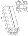
- 2A is an external view of the base frame 1
- FIG. 2B is a cross-sectional view taken along the line AA of the base frame 1 shown in FIG. 2A.
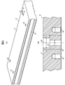
- 3A is an external view of the air rail 2
- FIG. 3B is an enlarged cross-sectional view taken along the line BB of the air rail 2 shown in FIG. 3A.
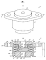
- 4A is an external view of the leveling device 3
- FIG. 4B is a cross-sectional view taken along the line CC of the leveling device 3 shown in FIG. 4A.
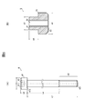
- FIG. 5A is an external view of the hexagon socket head cap bolt 4, and FIG.
- FIG. 5B is a cross-sectional view of the T-nut 5.
- FIG. 6A is a cross-sectional view for explaining the assembly work of the leveling device 3
- FIG. 6B is a cross-sectional view for explaining the work of attaching the leveling device 3 to the air rail 2.
- FIG. 7 is a cross-sectional view for explaining the mounting operation of the air rail 2 to the base frame 1.
- FIG. 1 is an external view showing a schematic configuration of a transport table 100 of a levitation transport apparatus according to an embodiment of the present invention.
- the levitation conveyance apparatus includes a conveyance table 100 that floats and conveys a conveyance object such as a glass substrate used for an FPD, a solar battery panel, or the like from the conveyance surface 21.
- the carriage 100 includes two prismatic base frames (for example, an aluminum frame) 1 arranged at a predetermined interval, and a plate-shaped air rail 2 spanned between the two base frames 1, There are two (four in total) leveling devices 3 (partially not shown) for each base frame 1 for supporting the air rail 2 on the base frame 1.
- the case where one air rail 2 is bridged between two base frames 1 is illustrated, but in reality, for example, two pieces having a length corresponding to the conveyance distance.
- a plurality of air rails 2 are arranged in the longitudinal direction of the base frame 1 (Y direction in FIG. 1).
- one air rail 2 is supported by four leveling devices 3, but the number of leveling devices 3 that can stably support the air rail 2 may be used.
- the transport table 100 further includes a bolt 6 for fixing the leveling device 3 to the air rail 2 and a hexagon for fixing the air rail 2 to the base frame 1 via the leveling device 3.
- Two bolts 6 are provided for each leveling device 3.
- one pair of hexagon socket head bolts 4 and T nuts 5 are provided for each leveling device 3 (four pairs in total).
- FIG. 2A is an external view of the base frame 1
- FIG. 2B is a cross-sectional view of the base frame 1 taken along line AA shown in FIG. 2A.
- a T-nut 5 is disposed at a desired position in the longitudinal direction of the base frame 1 on each of the four outer surfaces (the upper surface 12A, the left side surface 12B, the lower surface 12C, and the right side surface 12D) of the base frame 1.
- the T-shaped groove 11 is formed.
- the T-shaped groove 11 has a T-shaped cross-section including a step 113 that changes from the groove width s1 to the groove width s2 (> s1) between the groove edge 112 and the groove bottom 111. From one end surface (surface perpendicular to the longitudinal direction) 13 to the other end surface 14.
- the T-shaped groove 11 forms T-shaped openings on both end surfaces 13 and 14 of the base frame 1, and each of the four outer surfaces 12A to 12D continues from one end surface 13 to the other end surface 14.
- An opening having a groove width s1 is formed.
- a four-surface groove type frame in which T-shaped grooves 11 are formed on all four outer surfaces 12A to 12D is used, but at least on the air rail 2 side. Any frame may be used as long as the T-shaped groove 11 is formed on the upper surface 12A to be directed.
- FIG. 3A is an external view of the air rail 2
- FIG. 3B is an enlarged cross-sectional view taken along the line BB of the air rail 2 shown in FIG. 3A.
- the air rail 2 ejects compressed air supplied from the outside to an air supply port (not shown) from a plurality of air blowing holes (not shown) on the transport surface 21 via an internal air supply path (not shown). .
- the air rail 2 is attached to the base frame 1 at four positions (four positions in the present embodiment) from the transport surface 21 toward the back surface (surface opposite to the transport surface 21) 24, respectively.
- a stepped through hole 23 for inserting the hexagon socket head bolt 4 is formed.
- a step 25 is formed in which the seat surface 412 (see FIG. 5) of the hexagon socket head bolt 4 inserted into the stepped through hole 23 from the conveying surface 21 side comes into contact.
- the diameter r1 in the region (large diameter portion) 28 from the conveyance surface 21 to the step 25 is larger than the diameter r2 in the region (small diameter portion) 27 from the step 25 to the back surface 24.
- screw holes 26 to which the bolts 6 are fastened are formed on both sides of the stepped through hole 23 on the back surface 24 of the air rail 2.
- the stepped through hole 23 is formed at the position where the air rail 2 is attached to the base frame 1, but the position where the air rail 2 is attached to the base frame 1 can be adjusted, for example, In the longitudinal direction of the air rail 2, a stepped long hole having a cross-sectional shape similar to the cross-sectional shape of the stepped through hole 23 may be formed with an arbitrary length.
- FIG. 4A is an external view of the leveling device 3
- FIG. 4B is a cross-sectional view taken along the line CC of the leveling device 3 shown in FIG. 4A.
- the leveling device 3 supports the air rail 2 on the base frame 1 and adjusts the height of the air rail 2 with respect to the base frame 1.
- the leveling device 3 includes a disc spring group 31 that expands and contracts in the height direction of the air rail 2 with respect to the base frame 1 (the Z direction in FIG. 1), and an upper surface of the base frame 1 that is biased by the disc spring group 31.
- a cylindrical housing 34 with a flange portion and an edge portion.
- the housing 34 includes a cylindrical portion 343, a second edge portion 342 formed in the opening 341 on the one end face (the bottom surface 348 of the housing 34) side of the cylindrical portion 343 toward the inside of the cylindrical portion 343, and the cylindrical portion. And a flange portion 349 formed on the other end face (the upper surface 346 of the housing 34) side of the cylindrical portion 343 so as to protrude outward from the outer periphery of the 343.
- the housing 34 is disposed between the base frame 1 and the air rail 2 so that the upper surface 346 contacts the back surface 24 of the air rail 2 with the opening 344 on the upper surface 346 side facing the stepped through hole 23 of the air rail 2. Is done. Further, a third through hole 347 into which the bolt 6 is inserted is formed in the flange portion 349 at a position corresponding to the screw hole 26 on the back surface 24 of the air rail 2.
- the indenter 32 includes a cylindrical portion 325 that protrudes from the opening 341 on the bottom surface 348 side of the housing 34 to the base frame 1 side, and one end surface of the cylindrical portion 325 so as to protrude outward from the outer periphery of the cylindrical portion 325 (the indenter 32 And a first edge 322 formed on the upper surface 321) side.
- a first through hole 324 for inserting the hexagon socket head cap bolt 4 from the upper surface 321 toward the other end surface (the bottom surface 323 of the indenter 32) is formed in the cylindrical portion 325.
- the lower surface 326 of the first edge 322 is in contact with the upper surface 350 of the second edge 342 of the housing 34, and the bottom surface 323 protrudes from the opening 341 on the bottom surface 348 side of the housing 34 to the base frame 1 side. In this state, it is accommodated in the housing 34.
- the spring guide 33 is formed on the cylindrical portion 335 inserted into the disc spring group 31 in the housing 34, and on one end surface (the upper surface 331 of the spring guide 33) side of the cylindrical portion 335 so as to protrude from the outer periphery of the cylindrical portion 335. And a flange portion 332 that presses the disc spring group 31 between the upper surface 321 of the indenter 32 in the housing 34.
- a second through hole 334 for inserting the hexagon socket head bolt 4 from the upper surface 331 toward the bottom surface 333 is formed in the cylindrical portion 335.
- the length k1 from the bottom surface 333 of the cylindrical portion 335 of the spring guide 33 to the lower surface 336 of the flange portion 332 is smaller than the free height of the disc spring group 31, and the position of the upper surface 331 of the spring guide 33 is set to the housing 34.
- the clearance is set so that a gap more than the height adjustment allowance of the air rail 2 is formed between the bottom surface 333 of the spring guide 33 and the upper surface 321 of the indenter 32.
- the disc spring group 31 includes a plurality of disc springs 311 stacked in the height direction with respect to the base frame 1 of the air rail 2 in a cylindrical hollow portion 337.
- a plurality of disc springs 311 are overlapped so that the directions of adjacent disc springs 311 are reversed (so-called serial combination method), but the directions of adjacent disc springs 311 are the same.
- a plurality of disc springs 311 may be overlapped (so-called parallel combination method), or a combination of a so-called series method and parallel method may be used.
- six disc springs 311 are stacked, but the number of disc springs to be used can be changed as appropriate according to the embodiment.
- the disc spring group 31 urges the indenter 32 in a direction to push out from the opening 341 on the bottom surface 348 side of the housing 34, presses the indenter 32 against the upper surface 12 ⁇ / b> A of the base frame 1, and attaches the spring guide 33 to the upper surface of the housing 34.
- the spring guide 33 is urged in the direction of pushing out from the opening 344 on the 346 side, and the spring guide 33 is pressed against the back surface 24 of the air rail 2.
- the disc spring group 31 has an allowable load and a spring constant capable of stably supporting a load received during conveyance of the conveyance target (a conveyance target, a load applied to one leveling device 3 by the air rail 2 or the like). Yes. If it has such elasticity, instead of the disc spring group 31, another elastic body (coil spring, cylindrical rubber) having a shape that can be disposed in the cylindrical hollow portion 337. Etc.) may be used.
- a cylindrical spring guide 33 with a flange portion, a cylindrical indenter 32 with an edge portion, and a cylindrical housing 34 with a flange portion and an edge portion are used.
- Other three-dimensional spring guides 33, indenters 32, and housings 34 in which the axis of the group 31 is not displaced may be used.
- FIG. 5A is an external view of the hexagon socket head bolt 4.
- the hexagon socket head cap bolt 4 has a hexagon socket 43 for a hexagon wrench formed on the upper surface 411 of the head 41.
- the diameter r3 of the head portion 41 of the hexagon socket head bolt 4 is smaller than the diameter r1 of the large diameter portion 28 of the stepped through hole 23 of the air rail 2 and larger than the diameter r2 of the small diameter portion 27.
- the thickness k2 of the head 41 of the hexagon socket head cap bolt 4 is smaller than the length k3 of the large diameter portion 28 of the stepped through hole 23 of the air rail 2 (see FIG. 3B).
- the seat surface 412 penetrates the stepped surface at a position where the head 41 comes below the conveying surface 21.
- the head 41 is completely accommodated in the large-diameter portion 28 of the stepped through hole 23 in contact with the step 25 of the hole 23.
- the length k4 from the seating surface 412 of the hexagon socket head cap bolt 4 to the screw portion 42 is equal to the length k5 of the small diameter portion 27 of the stepped through hole 23 of the air rail 2 (see FIG. 3B) and the leveling device. 3 (the length from one opening 341 to the other opening 344) k6 (see FIG. 4B) is smaller than the total. 4B, the first edge 322 of the indenter 32 contacts the second edge 342 of the housing 34, and the bottom surface 323 of the indenter 32 protrudes from the opening 341 of the housing 34.
- the length k7 from the seating surface 412 of the hexagon socket head cap bolt 4 to the tip 421 of the screw portion 42 is the length k8 from the bottom surface 323 of the indenter 32 to the top surface 346 of the housing 34, and the step of the air rail 2 is stepped. It is larger than the sum of the length k5 of the small diameter portion 27 of the through hole 23 and the depth k10 (see FIG. 2B) from the groove edge 112 to the step 113 of the T-shaped groove 11 of the base frame 1 and the above-mentioned. And a depth k11 (see FIG. 2 (B)) from the groove edge 112 to the groove bottom 111 of the T-shaped groove 11 of the base frame 1 is smaller than the total.
- FIG. 5B is a cross-sectional view of the T-nut 5.
- the T-nut 5 has a T-shaped cross section including a step 52 whose width changes from s3 to s4 (> s3) from one end surface (upper surface 51) to the other end surface (bottom surface 53).
- a screw hole 54 having a shape and penetrating from the upper surface 51 to the bottom surface 53 and screwed with the screw portion 42 of the hexagon socket head bolt 4 is formed.
- the width s3 from the upper surface 51 to the step 52 is smaller than the groove width s1 (see FIG. 2B) from the groove edge 112 to the step 113 of the T-shaped groove 11 of the base frame 1.
- the width s4 from the step 52 to the bottom surface 53 is larger than the groove width s1 from the groove edge 112 to the step 113 of the T-shaped groove 11 of the base frame 1 and from the step 113 to the groove bottom 111 of the T-shaped groove 11. It is smaller than the groove width s2 (see FIG. 2B). Further, the height k9 from the step 52 to the upper surface 51 is not more than the depth k10 (see FIG. 2B) from the groove edge 112 to the step 113 of the T-shaped groove 11 of the base frame 1.
- the T-nut 5 can be arranged at a desired position in the T-shaped groove 11 of the base frame 1, and the T-shaped groove 11 is fastened by fastening the screw portion 42 and the screw hole 54 of the hexagon socket head bolt 4.
- the step 52 comes into contact with the step 113 of the T-shaped groove 11 and is fixed to the base frame 1.
- FIG. 6A is a cross-sectional view for explaining the assembly work of the leveling device 3
- FIG. 6B is a cross-sectional view for explaining the work of attaching the leveling device 3 to the air rail 2.
- FIG. FIG. 7 is a cross-sectional view for explaining the mounting operation of the air rail 2 to the base frame 1.
- the indenter 32 is inserted into the housing 34 from the bottom surface 323 side, and the first edge 322 of the indenter 32 is brought into contact with the second edge 342 of the housing 34.
- a plurality of disc springs 311 are stacked on the indenter 32 accommodated in the housing 34 so that the directions of the adjacent disc springs 311 are reversed.
- the spring guide 33 is inserted into the housing 34 from the bottom surface 333 side, and the cylindrical portion 335 of the spring guide 33 is inserted into the disc spring group 31.
- the indenter 32, the disc spring group 31, and the spring guide 33 are accommodated in the housing 34 in order, and the leveling apparatus 3 as shown to FIG. 4 (A) and (B) is completed.
- the spring guide 33 is pushed into the housing 34 until the upper surface 331 of the spring guide 33 is at the same position as the upper surface 346 of the housing 34, and the disc spring group 31 is preloaded. At this time, the length of the protruding portion of the indenter 32 from the bottom surface 348 of the housing 34 is c1, and the length from the bottom surface 333 of the spring guide 33 to the upper surface 321 of the indenter 32 is c2.
- the air rail 2 is arranged so as to be spanned between the two base frames 1.
- Two T nuts 5 are inserted into the T-shaped groove 11 on the upper surface 12 ⁇ / b> A side of the base frame 1, and these T nuts 5 are arranged at positions corresponding to the stepped through holes 23 of the air rail 2.
- the hexagon socket head cap bolt 4 is connected to the stepped through hole 23 of the air rail 2, the second through hole 334 of the spring guide 33, and the indenter 32 of the indenter 32 from the conveying surface 21 side of the air rail 2.
- the screw portion 42 of the hexagon socket head bolt 4 is screwed into the screw hole 54 of the T nut 5 using the hexagon wrench 7.
- the air rail 2 passes through the leveling device 3 while the bottom surface 323 of the indenter 32 protruding from the opening 341 on the bottom surface 348 side of the housing 34 to the base frame 1 side is in contact with the top surface 12A of the base frame 1. Attached to the base frame 1.
- the length k4 (see FIG. 5A) from the seating surface 412 of the head portion 41 of the hexagon socket head cap bolt 4 to the screw portion 42 is the length of the small diameter portion 27 of the stepped through hole 23 of the air rail 2.
- the length k5 (see FIG. 3B) and the height of the housing 34 of the leveling device 3 (the length from one opening 341 to the other opening 344) k6 (see FIG. 4B) Less than total.
- the length k7 (see FIG.
- the height adjustment allowance (of c1, c2 shown in FIG. 6B and the maximum amount of contraction of the disc spring group 31)
- the height of the air rail 2 relative to the base frame 1 can be adjusted within the range of the smallest length.
- a disc spring group 31, an indenter 32, and a spring guide 33 are accommodated in a housing 34, and a plurality of configurations including the disc spring group 31, the indenter 32, the spring guide 33, and the housing 34 are included. Since the parts are unitized, it is possible to assemble the required number in advance prior to the work of attaching the air rail 2 to the base frame 1. For this reason, the operator can easily attach the leveling device 3 to the air rail 2 without worrying about dropping of some parts, and the working efficiency is improved.
- the hexagon socket head bolt 4 is attached a smaller number of times compared to the case where the disc spring group 31 is not preloaded.
- the air rail 2 can be attached to the base frame 1 simply by tightening to the T-nut 5.
- the upper surface 331 of the spring guide 33 is pushed to the same position as the upper surface 346 of the housing 34, and the disc spring group 31 is preloaded, so that the air rail 2 is attached to the base frame 1.
- An equal preload can be applied to the four leveling devices 3 used for the mounting work without performing troublesome preload adjustment.
- the hexagon socket head cap bolt 4 is inserted into the stepped through hole 23 from the air rail 2 conveying surface 21 side and screwed to the T-nut 5 so that the air rail 2 is attached to the base frame 1 and the hexagon socket head is provided. Since the height of the air rail 2 with respect to the base frame 1 is adjusted by adjusting the tightening degree of the bolt 4, unlike the substrate transfer device described in Patent Document 1, the height adjustment gap is formed in the longitudinal direction of the air rail 2 ( It is not necessary to secure them on both sides in the X direction in FIG. Therefore, when a plurality of air rails 2 are arranged, the distance between the plurality of air rails 2 can be set flexibly in consideration of the floating stability of the object to be transported, such as adhering adjacent air rails 2. For this reason, it is possible to convey the object to be conveyed more stably.
- the bolt 6 is screwed into the screw hole 26 formed in the back surface 24 of the air rail 2 through the third through hole 347 formed in the housing 34 of the leveling device 3, thereby allowing the disc spring group 31 to be fixed. Since the leveling device 3 is attached to the air rail 2 with the preload applied, the leveling device 3 is attached to the required number of air rails 2 and the preloading work is performed in advance before the air rail 2 is attached to the base frame 1. It becomes possible. For this reason, work efficiency further improves.
- the air rail 2 is attached to the base frame 1 via the leveling device 3 using the hexagon socket bolt 4 and the T-nut 5, but the present invention is not limited to this.
- the present invention is not limited to this.
- the air rail 2 may be attached to the base frame 1.
- a hexagon socket is used to enable the mounting of the air rail 2 to the base frame 1 and the leveling of the transport surface 21 from the transport surface 21 side of the air rail 2 using the hexagon wrench 7.
- the bolt 4 is used, the present invention is not limited to this.
- a bolt having a cross hole, a slit groove or the like formed on the upper surface of the head may be used.
- the air rail 2 is attached to the base frame 1 so as to be passed over the two prismatic base frames 1 arranged at a predetermined interval. It is not limited.
- the air rail 2 may be attached to the base frame 1 so as to be placed on a single plate-like base frame.
- the application to the levitating conveyance apparatus having the conveyance table 100 has been described as an example.
- the present invention is also applicable to other apparatuses in which the table having the leveling target surface is fixed to the base material. Is possible.
- this invention is the separation distance between two members.
- the present invention can be widely applied to a separation distance adjusting device that adjusts.
- the present invention relates to a member having a leveling target surface, such as a transporting device in which a rail having a transporting surface to be leveled is fixed to the base material, a device in which a table having a leveling target surface is fixed to the base material, and the like.
- the present invention can be applied to an application where it is necessary to adjust the distance between two members with good workability, such as leveling in an apparatus fixed to another member.
Landscapes
- Engineering & Computer Science (AREA)
- Mechanical Engineering (AREA)
- General Engineering & Computer Science (AREA)
- Physics & Mathematics (AREA)
- Fluid Mechanics (AREA)
- Container, Conveyance, Adherence, Positioning, Of Wafer (AREA)
- Fluid-Damping Devices (AREA)
Abstract
本発明のレベリング装置(3)は、ベースフレーム(1)上でエアレール(2)を支持し、ベースフレーム(1)に対するエアレール(2)の高さを調整する。レベリング装置(3)は、ベースフレーム(1)に対するエアレール(2)の高さ方向に伸縮する皿バネ群と、一方の端面から他方の端面(323)に向けてボルト(4)を挿入するための第一の貫通孔(324)が形成され、外側に向けて第一の縁部が一方の端面側に形成された円柱状の圧子と、一方の端面から他方の端面に向けてボルト(4)を挿入するための第二の貫通孔(334)が形成され、外側に向けてフランジ部が一方の端面側に形成され円柱状のスプリングガイドと、内側に向けて第二の縁部が一方の開口部に形成された筒状のハウジングと、を有する。本発明は、これにより、二つの部材間(ベースフレーム(1)とエアレール(2))の離間距離調整作業の作業性向上を図る。
Description
本発明は、離間距離調整装置に関し、特に、搬送物を浮上させて搬送する浮上搬送装置に好適なレベリング装置の構造に関する。
フラットパネルディスプレイ(FPD)に用いられる基板等を搬送面から浮上させて搬送する浮上搬送装置として、特許文献1記載の基板搬送装置が知られている。
この浮上搬送装置は、配列された複数の浮上ブロックの搬送面から圧縮空気を噴出させることによって搬送対象の基板を浮上させながら、この基板を搬送方向に搬送する。ここで、各浮上ブロックの搬送面の高さおよび平面度を調整可能とするため、各浮上ブロックは個別の可動プレート上にネジで固定されており、これらの可動プレートと固定プレートとの間隔がそれぞれ3点で調整できるようになっている。
具体的には、浮上ブロックの底部両側からはり出す可動プレートには合計3ケ所に雌ネジが切られており、固定プレートには、各可動プレートの雌ネジに対向する位置に、それらの雌ネジとはピッチの異なる雌ネジが切られている。そして、可動プレートの雌ネジと固定プレートの雌ネジとにかみあう雄ネジ部を有する調整ネジが、可動プレートと固定プレートとの間に介在するバネ内に挿入された状態で、対向する各組の雌ネジに締結されている。作業者は、隣り合う浮上ブロックの間に工具を差し入れて調整ネジを回転させることにより、可動プレートと固定プレートとの間隔を、両プレートの雌ネジのピッチ差分に相当する距離ずつ増減させ、調節することができる。
しかし、特許文献1に記載の基板搬送装置では、可動プレートを固定プレートに取り付ける際、作業者は、可動プレートの各雌ネジにねじ込んだ調整ネジにそれぞれバネを挿入し、これらのバネが抜け落ちないように保持しながら、各調整ネジの先端を、固定プレートの対応する雌ネジに位置付ける必要がある。このため、作業性がよくない。
また、作業者が調整ネジの締め・緩め作業を行うための空間を浮上ブロックの両側に確保しておく必要があるため、隣り合う浮上ブロックの間隔をさらに狭くしたり、隣り合う浮上ブロックを密着させたりすることができない。このため、隣り合う浮上ブロックの隙間の位置で、搬送対象に良好な状態で圧縮空気を吹き付けることができず、搬送対象の浮上状態が不安定になる可能性がある。
本発明は上記事情に鑑みてなされたものであり、その目的は、二つの部材間の離間距離調整作業の作業性を向上させる技術を提供することにある。
上記課題を解決するために、本発明は、二つの部材間の離間距離を調整する離間距離調整装置において、弾性体等を含む複数の構成部品をユニット化可能な構造とするとともに、一方の部材の他方の部材への取付け、および離間距離の調整をボルト一本で行えるようした。
例えば、本発明は、二つの部材の間に位置して、当該二つの部材間の離間距離を調整する離間距離調整装置であって、
前記離間距離方向に伸縮する弾性体と、
一方の端面から他方の端面に向けて第一の貫通孔が形成され、外側に向けて第一の縁部が前記一方の端面側に形成された筒状の圧子と、
一方の端面から他方の端面に向けて第二の貫通孔が形成され、外側に向けてフランジ部が前記一方の端面側に形成された筒状のガイド部材と、
内側に向けて第二の縁部が一方の開口部に形成された筒状のハウジングと、を有し、
前記ハウジングは、
前記一方の開口部と反対側の他方の開口部が前記二つの部材のうちの一方の部材と対向するように、前記二つの部材の間に配置され、
前記圧子は、
前記第一の縁部が前記第二の縁部と接して、当該圧子の前記他方の端面が前記ハウジングの一方の開口部から突出するように、前記ハウジング内に収容され、
前記ガイド部材は、
前記第二の貫通孔の軸心が前記第一の貫通孔の軸心と一致するように、前記圧子が収容された前記ハウジング内に収容されて、前記ハウジングの内面、前記ガイド部材の側面、前記第一の縁部、および前記フランジ部により筒状の中空部が形成され、
前記弾性体は、
前記ガイド部材を、前記ハウジングの他方の開口部から押し出す方向に付勢して、前記二つの部材のうちの一方の部材に圧接させるように、前記中空部に設けられる。
前記離間距離方向に伸縮する弾性体と、
一方の端面から他方の端面に向けて第一の貫通孔が形成され、外側に向けて第一の縁部が前記一方の端面側に形成された筒状の圧子と、
一方の端面から他方の端面に向けて第二の貫通孔が形成され、外側に向けてフランジ部が前記一方の端面側に形成された筒状のガイド部材と、
内側に向けて第二の縁部が一方の開口部に形成された筒状のハウジングと、を有し、
前記ハウジングは、
前記一方の開口部と反対側の他方の開口部が前記二つの部材のうちの一方の部材と対向するように、前記二つの部材の間に配置され、
前記圧子は、
前記第一の縁部が前記第二の縁部と接して、当該圧子の前記他方の端面が前記ハウジングの一方の開口部から突出するように、前記ハウジング内に収容され、
前記ガイド部材は、
前記第二の貫通孔の軸心が前記第一の貫通孔の軸心と一致するように、前記圧子が収容された前記ハウジング内に収容されて、前記ハウジングの内面、前記ガイド部材の側面、前記第一の縁部、および前記フランジ部により筒状の中空部が形成され、
前記弾性体は、
前記ガイド部材を、前記ハウジングの他方の開口部から押し出す方向に付勢して、前記二つの部材のうちの一方の部材に圧接させるように、前記中空部に設けられる。
本発明によれば、二つの部材間の離間距離調整作業の作業性を向上させることができる。
以下、本発明の一実施の形態を説明する。
図1は、本発明の一実施の形態に係る浮上搬送装置の搬送台100の概略構成を示す外観図である。
図示するように、本実施の形態に係る浮上搬送装置は、FPD、太陽電池パネル等に用いられるガラス基板等の搬送物を搬送面21から浮上させて搬送する搬送台100を備えている。この搬送台100は、所定の間隔をおいて並べられた2本の角柱状のベースフレーム(例えばアルミフレーム)1と、2本のベースフレーム1の間にかけ渡された板状のエアレール2と、ベースフレーム1上でエアレール2を支えるための、ベースフレーム1毎に2本(合計4本)のレベリング装置3(一部不図示)と、を有する。なお、本実施の形態では、2本のベースフレーム1の間に1本のエアレール2がかけ渡された場合を例示しているが、実際には、例えば搬送距離分の長さを有する2本のベースフレーム1の間に、複数本のエアレール2がベースフレーム1の長手方向(図1のY方向)に並べてかけ渡される。また、本実施の形態では、1本のエアレール2を4本のレベリング装置3で支持しているが、エアレール2を安定に支持可能な本数のレベリング装置3を用いればよい。
また、図1には図示していないが、搬送台100は、さらに、エアレール2にレベリング装置3を固定するボルト6と、レベリング装置3を介してエアレール2をベースフレーム1に固定するための六角穴付きボルト4およびTナット5と、を有する。ボルト6は、レベリング装置3毎に2本設けられている。また、六角穴付きボルト4およびTナット5は、レベリング装置3毎に1対(合計4対)設けられている。
図2(A)は、ベースフレーム1の外観図であり、図2(B)は、図2(A)に示すベースフレーム1のA-A断面図である。
図示するように、ベースフレーム1の4つの外面(上面12A、左側面12B、下面12Cおよび右側面12D)の各々には、ベースフレーム1の長手方向の所望の位置にTナット5を配置するためのT字状溝11が形成されている。T字状溝11は、溝縁112から溝底111までの間において溝幅s1から溝幅s2(>s1)に変わる段差113を含むT字状の断面形状を有し、ベースフレーム1の一方の端面(長手方向に垂直な面)13から他方の端面14まで連続している。このT字状溝11により、ベースフレーム1の両端面13、14にはT字状の開口が形成され、4つの外面12A~12Dの各々にも、一方の端面13から他方の端面14まで連続する溝幅s1の開口が形成される。
なお、本実施の形態では、ベースフレーム1として、4つの外面12A~12DのすべてにT字状溝11が形成された4面溝タイプのフレームを使用しているが、少なくとも、エアレール2側に向けられる上面12AにT字状溝11が形成されたフレームであればよい。
図3(A)は、エアレール2の外観図であり、図3(B)は、図3(A)に示すエアレール2のB-B断面拡大図である。
エアレール2は、外部からエア供給口(不図示)に供給された圧縮空気を、内部のエア供給路(不図示)を介して、搬送面21の複数のエア吹き出し穴(不図示)から噴出する。
図示するように、このエアレール2のベースフレーム1への取付け位置(本実施の形態では4ヶ所)には、それぞれ、搬送面21から裏面(搬送面21とは反対側の面)24に向けて六角穴付きボルト4を挿入するための段付き貫通孔23が形成されている。段付き貫通孔23には、この段付き貫通孔23に搬送面21側から挿入される六角穴付きボルト4の座面412(図5参照)が接触する段差25が形成されている。搬送面21から段差25までの領域(大径部)28における直径r1は、段差25から裏面24までの領域(小径部)27における直径r2より大きい。
また、エアレール2の裏面24には、段付き貫通孔23の両側に、ボルト6が締結されるネジ穴26が形成されている。
なお、本実施の形態では、エアレール2のベースフレーム1への取付け位置に段付き貫通孔23を形成しているが、エアレール2のベースフレーム1への取付け位置が調整可能となるように、例えばエアレール2の長手方向に、段付き貫通孔23の断面形状と同様な断面形状の段付き長穴を任意の長さで形成してもよい。
図4(A)は、レベリング装置3の外観図であり、図4(B)は、図4(A)に示すレベリング装置3のC-C断面図である。
レベリング装置3は、ベースフレーム1上でエアレール2を支持し、ベースフレーム1に対するエアレール2の高さを調整する。
図示するように、レベリング装置3は、ベースフレーム1に対するエアレール2の高さ方向(図1のZ方向)に伸縮する皿バネ群31と、皿バネ群31に付勢されてベースフレーム1の上面12Aに押し当てられる縁部付円筒状の圧子32と、皿バネ群31に付勢されてエアレール2の裏面24に押し当てられるフランジ部付円筒状のスプリングガイド33と、これらの部品31~33を収容するフランジ部および縁部付円筒状のハウジング34と、を有する。
ハウジング34は、円筒部343と、円筒部343の内側に向けて円筒部343の一方の端面(ハウジング34の底面348)側の開口部341に形成された第二の縁部342と、円筒部343の外周から外側にはりだすように円筒部343の他方の端面(ハウジング34の上面346)側に形成されたフランジ部349と、を有している。
このハウジング34は、上面346側の開口部344がエアレール2の段付き貫通孔23に対向する状態で上面346がエアレール2の裏面24と接するように、ベースフレーム1とエアレール2との間に配置される。また、フランジ部349には、エアレール2の裏面24のネジ穴26に対応する位置に、ボルト6が挿入される第三の貫通孔347が形成されている。
圧子32は、ハウジング34の底面348側の開口部341からベースフレーム1側に突出する円柱部325と、円柱部325の外周から外側にはりだすように円柱部325の一方の端面(圧子32の上面321)側に形成された第一の縁部322と、を有する。円柱部325には、上面321から他方の端面(圧子32の底面323)に向けて六角穴付きボルト4を挿入するための第一の貫通孔324が形成されている。
この圧子32は、第一の縁部322の下面326がハウジング34の第二の縁部342の上面350と接し、底面323がハウジング34の底面348側の開口部341からベースフレーム1側に突出した状態でハウジング34内に収容される。
スプリングガイド33は、ハウジング34内の皿バネ群31に挿入される円柱部335と、円柱部335の外周からはりだすように円柱部335の一方の端面(スプリングガイド33の上面331)側に形成され、ハウジング34内の圧子32の上面321との間で皿バネ群31を押圧するフランジ部332と、を有する。円柱部335には、上面331から底面333に向けて六角穴付きボルト4を挿入するための第二の貫通孔334が形成されている。
このスプリングガイド33が、第二の貫通孔334の軸心が圧子32の第一の貫通孔324の軸心と一致するようにハウジング34内に収容されると、円柱部335の外周面339、フランジ部332の下面336、ハウジング34の内面345、および圧子32の上面321により筒状の中空部337が形成される。
なお、スプリングガイド33の円柱部335の底面333からフランジ部332の下面336までの長さk1は、皿バネ群31の自由高さよりも小さく、かつ、スプリングガイド33の上面331の位置をハウジング34の上面346の位置に揃えたときに、スプリングガイド33の底面333と圧子32の上面321との間にエアレール2の高さ調整代以上の隙間が形成される寸法に設定されている。
皿バネ群31は、筒状の中空部337内でエアレール2のベースフレーム1に対する高さ方向に積み重ねられた複数枚の皿バネ311により構成されている。本実施の形態では、隣り合う皿バネ311の向きが逆になるように複数枚の皿バネ311を重ね合わせているが(いわゆる直列組合せ方式)、隣り合う皿バネ311の向きが同じになるように複数枚の皿バネ311を重ね合わせても(いわゆる並列組合せ方式)、あるいはいわゆる直列方式と並列方式との組合せでもよい。また、本実施の形態では、6枚の皿バネ311を積み重ねているが、実施の形態によって、使用する皿バネの枚数は適宜変更可能である。
この皿バネ群31は、圧子32をハウジング34の底面348側の開口部341から押し出す方向に付勢し、圧子32をベースフレーム1の上面12Aに圧接するとともに、スプリングガイド33をハウジング34の上面346側の開口部344から押し出す方向に付勢し、スプリングガイド33をエアレール2の裏面24に圧接する。また、皿バネ群31は、搬送対象の搬送中に受ける荷重(搬送対象、エアレール2等によりレベリング装置3一本あたりにかかる荷重等)を安定に支持可能な許容荷重およびばね定数を有している。このような弾性を有しているものであれば、皿バネ群31の代わりに、筒状の中空部337内に配置することが可能な形状を有する他の弾性体(コイルバネ、筒状のゴム等)を用いてもよい。
なお、本実施の形態においては、フランジ部付円筒状のスプリングガイド33と、縁部付円筒状の圧子32と、フランジ部および縁部付円筒状のハウジング34とを用いているが、皿バネ群31の軸心がずれない他の立体形状のスプリングガイド33、圧子32およびハウジング34を用いてもよい。
図5(A)は、六角穴付きボルト4の外観図である。
図示するように、六角穴付きボルト4は、頭部41の上面411に六角レンチ用の六角穴43が形成されている。六角穴付きボルト4の頭部41の直径r3は、エアレール2の段付き貫通孔23の大径部28の直径r1よりも小さく、かつ小径部27の直径r2よりも大きい。また、六角穴付きボルト4の頭部41の厚さk2は、エアレール2の段付き貫通孔23の大径部28の長さk3(図3(B)参照)よりも小さい。このため、六角穴付きボルト4は、エアレール2の搬送面21側から段付き貫通孔23に挿入されたとき、頭部41が搬送面21より下側にきた位置で座面412が段付き貫通孔23の段差25に接触して、段付き貫通孔23の大径部28内に頭部41が完全に収容される。
また、六角穴付きボルト4の座面412からネジ部42までの長さk4は、エアレール2の段付き貫通孔23の小径部27の長さk5(図3(B)参照)と、レベリング装置3のハウジング34の高さ(一方の開口部341から他方の開口部344までの長さ)k6(図4(B)参照)との合計より小さい。また、図4(B)に示すように、圧子32の第一の縁部322がハウジング34の第二の縁部342と接触して、圧子32の底面323がハウジング34の開口部341から突出している状態において、六角穴付きボルト4の座面412からネジ部42の先端421までの長さk7は、圧子32の底面323からハウジング34の上面346までの長さk8、エアレール2の段付き貫通孔23の小径部27の長さk5、およびベースフレーム1のT字状溝11の溝縁112から段差113までの深さk10(図2(B)参照)の合計より大きく、かつ、上述のk8、k5、およびベースフレーム1のT字状溝11の溝縁112から溝底111までの深さk11(図2(B)参照)の合計より小さい寸法とされている。
図5(B)は、Tナット5の断面図である。
図示するように、Tナット5は、一方の端面(上面51)から他方の端面(底面53)までの間において、幅がs3からs4(>s3)に変わる段差52を含むT字状の断面形状を有しており、上面51から底面53まで貫通した、六角穴付きボルト4のネジ部42と螺合するネジ穴54が形成されている。上面51から段差52までにおける幅s3は、ベースフレーム1のT字状溝11の溝縁112から段差113までにおける溝幅s1(図2(B)参照)よりも小さい。段差52から底面53までにおける幅s4は、ベースフレーム1のT字状溝11の溝縁112から段差113までにおける溝幅s1より大きく、かつT字状溝11の段差113から溝底111までにおける溝幅s2(図2(B)参照)より小さい。また、段差52から上面51までの高さk9は、ベースフレーム1のT字状溝11の溝縁112から段差113までの深さk10(図2(B)参照)以下の寸法である。このため、Tナット5は、ベースフレーム1のT字状溝11内の所望の位置に配置でき、また、六角穴付きボルト4のネジ部42とネジ穴54との締結によりT字状溝11の溝底111から溝縁112の方向に力が加えられると、段差52がT字状溝11の段差113に接触し、ベースフレーム1に固定される。
つぎに、ベースフレーム1へのエアレール2の取付け作業について説明する。
図6(A)は、レベリング装置3の組立て作業を説明するための断面図であり、図6(B)は、エアレール2へのレベリング装置3の取付け作業を説明するための断面図である。また、図7は、ベースフレーム1へのエアレール2の取付け作業を説明するための断面図である。
(1)レベリング装置3の組立て
ベースフレーム1へのエアレール2の取付けに必要な本数(本実施の形態では4本)のレベリング装置3をあらかじめ組み立てておく。具体的には、以下の通りである。
ベースフレーム1へのエアレール2の取付けに必要な本数(本実施の形態では4本)のレベリング装置3をあらかじめ組み立てておく。具体的には、以下の通りである。
図6(A)に示すように、圧子32を底面323側からハウジング34内に挿入し、圧子32の第一の縁部322をハウジング34の第二の縁部342に当接させる。つぎに、隣り合う皿バネ311の向きが逆になるように、複数枚の皿バネ311を、ハウジング34内に収容された圧子32上に積み重ねる。それから、スプリングガイド33を底面333側からハウジング34内に挿入して、スプリングガイド33の円柱部335を皿バネ群31に挿入する。これにより、圧子32、皿バネ群31、およびスプリングガイド33が順番にハウジング34内に収容され、図4(A)、(B)に示すようなレベリング装置3が完成する。
(2)エアレール2へのレベリング装置3の取付け
図6(B)に示すように、レベリング装置3ごとに、2本のボルト6を、ハウジング34の第三の貫通孔347を介して、エアレール2の裏面24のネジ穴26にネジ止めする。これにより、スプリングガイド33の第二の貫通孔334および圧子32の第一の貫通孔324の軸心がエアレール2の段付き貫通孔23の軸心と一致した状態でハウジング34の上面346がエアレール2の裏面24と当接し、レベリング装置3がエアレール2の裏面24に取り付けられる。
図6(B)に示すように、レベリング装置3ごとに、2本のボルト6を、ハウジング34の第三の貫通孔347を介して、エアレール2の裏面24のネジ穴26にネジ止めする。これにより、スプリングガイド33の第二の貫通孔334および圧子32の第一の貫通孔324の軸心がエアレール2の段付き貫通孔23の軸心と一致した状態でハウジング34の上面346がエアレール2の裏面24と当接し、レベリング装置3がエアレール2の裏面24に取り付けられる。
これにより、スプリングガイド33の上面331が、ハウジング34の上面346と同じ位置にくるまで、スプリングガイド33がハウジング34内に押し込まれ、皿バネ群31にプリロードがかかる。このときの圧子32のハウジング34の底面348からの突出部分の長さをc1とし、スプリングガイド33の底面333から圧子32の上面321までの長さをc2とする。
(3)ベースフレーム1へのエアレール2の取付けと高さ調整
エアレール2を2本のベースフレーム1の間にかけ渡すように配置する。ベースフレーム1の上面12A側のT字状溝11に2つのTナット5を挿入し、これらのTナット5を、エアレール2の段付き貫通孔23に対応する位置に配置する。つぎに、図7に示すように、六角穴付きボルト4を、エアレール2の搬送面21側から、エアレール2の段付き貫通孔23、スプリングガイド33の第二の貫通孔334、圧子32の第一の貫通孔324に挿入し、六角レンチ7を使って六角穴付きボルト4のネジ部42をTナット5のネジ穴54にネジ止めする。これにより、ハウジング34の底面348側の開口部341からベースフレーム1側に突出している圧子32の底面323がベースフレーム1の上面12Aと当接した状態で、エアレール2がレベリング装置3を介してベースフレーム1に取り付けられる。
エアレール2を2本のベースフレーム1の間にかけ渡すように配置する。ベースフレーム1の上面12A側のT字状溝11に2つのTナット5を挿入し、これらのTナット5を、エアレール2の段付き貫通孔23に対応する位置に配置する。つぎに、図7に示すように、六角穴付きボルト4を、エアレール2の搬送面21側から、エアレール2の段付き貫通孔23、スプリングガイド33の第二の貫通孔334、圧子32の第一の貫通孔324に挿入し、六角レンチ7を使って六角穴付きボルト4のネジ部42をTナット5のネジ穴54にネジ止めする。これにより、ハウジング34の底面348側の開口部341からベースフレーム1側に突出している圧子32の底面323がベースフレーム1の上面12Aと当接した状態で、エアレール2がレベリング装置3を介してベースフレーム1に取り付けられる。
上述したように、六角穴付きボルト4の頭部41の座面412からネジ部42までの長さk4(図5(A)参照)は、エアレール2の段付き貫通孔23の小径部27の長さk5(図3(B)参照)と、レベリング装置3のハウジング34の高さ(一方の開口部341から他方の開口部344までの長さ)k6(図4(B)参照)との合計より小さい。また、圧子32の第一の縁部322がハウジング34の第二の縁部342と接触して、圧子32の底面323がハウジング34の開口部341から突出している状態において、六角穴付きボルト4の座面412からネジ部42の先端421までの長さk7(図5(A)参照)は、圧子32の端面323からハウジング34の上面346までの長さk8(図4(B)参照)、エアレール2の段付き貫通孔23の小径部27の長さk5(図3(B)参照)、およびベースフレーム1のT字状溝11の溝縁112から段差113までの深さk10(図2(B)参照)の合計より大きく、かつ上述のk8、k5、およびベースフレーム1のT字状溝11の溝縁112から溝底111までの深さk11(図2(B)参照)の合計より小さい。
このため、Tナット5への六角穴付きボルト4の締め具合を調節することにより、高さ調整代(図6(B)に示すc1、c2、および皿バネ群31の最大縮み量のうちの最も小さい長さ)の範囲内で、ベースフレーム1に対するエアレール2の高さを調整できる。この高さ調節作業を、エアレール2のベースフレーム1への取付けに用いる4本のレベリング装置3のそれぞれに対して行うことにより、エアレール2の搬送面21のレベリングを行う。
以上、本発明の一実施の形態を説明した。
本実施の形態に係るレベリング装置3は、皿バネ群31、圧子32およびスプリングガイド33がハウジング34内に収容されて、皿バネ群31、圧子32、スプリングガイド33、ハウジング34を含む複数の構成部品がユニット化されているため、エアレール2のベースフレーム1への取付け作業に先だって、あらかじめ必要本数を組み立てておくことが可能である。このため、作業者は、一部の部品の落下等を気にすることなく簡単に、レベリング装置3をエアレール2に取り付けることができ、作業効率が向上する。
また、レベリング装置3をエアレール2に取り付けることにより、レベリング装置3の皿バネ群31にプリロードがかかるため、皿バネ群31がプリロードされていない場合と比較して少ない回数、六角穴付きボルト4をTナット5に締め付けるだけで、エアレール2をベースフレーム1に取り付けることができる。
また、レベリング装置3をエアレール2に取り付けることにより、スプリングガイド33の上面331がハウジング34の上面346と同じ位置まで押し込まれて皿バネ群31にプリロードがかかるので、エアレール2のベースフレーム1への取付け作業に使用する4本のレベリング装置3に対して、面倒なプリロード調整を行わなくても、均等なプリロードをかけておくことができる。
また、六角穴付きボルト4を、エアレール2の搬送面21側から段付き貫通孔23に挿入して、Tナット5にネジ止めすることにより、エアレール2をベースフレーム1に取り付けるとともに、六角穴付きボルト4の締め具合を調節することで、エアレール2のベースフレーム1に対する高さを調整するので、特許文献1に記載の基板搬送装置と異なり、高さ調整用の隙間をエアレール2の長手方向(図1のX方向)の両側に確保しておく必要がない。したがって、複数のエアレール2を並べた場合、隣り合うエアレール2を密着させる等、複数のエアレール2の間隔寸法を、搬送対象の浮上安定性等を考慮して柔軟に設定することができる。このため、搬送対象をより安定に浮上させて搬送できる。
また、レベリング装置3のハウジング34に形成された第三の貫通孔347を介して、ボルト6を、エアレール2の裏面24に形成されたネジ穴26にネジ止めすることにより、皿バネ群31にプリロードをかけた状態で、レベリング装置3をエアレール2に取り付けるので、エアレール2のベースフレーム1への取付け作業に先だって、必要本数のエアレール2へのレベリング装置3の取付けおよびプリロード作業をあらかじめ行っておくことが可能となる。このため、作業効率がさらに向上する。
なお、本実施の形態では、六角穴付きボルト4およびTナット5を用いて、レベリング装置3を介してベースフレーム1にエアレール2を取り付けているが、本発明はこれに限定されない。ベースフレーム1の上面12Aの、エアレール2の段付き貫通孔23に対応する位置に、六角穴付きボルト4のネジ部42と螺合するネジ穴を形成することで、Tナット5を用いずにエアレール2をベースフレーム1に取り付けられるようにしてもよい。
また、本実施の形態では、六角レンチ7を使って、エアレール2の搬送面21側から、ベースフレーム1へのエアレール2の取付けおよび搬送面21のレベリングを行えるようにするために、六角穴付きボルト4を用いているが、本発明はこれに限定されない。使用する工具を応じて、例えば、十字穴、すり割り溝等が頭部の上面に形成されたボルトを用いればよい。
また、本実施の形態では、所定の間隔をおいて並べられた2本の角柱状のベースフレーム1上にかけ渡すようにして、エアレール2をベースフレーム1に取り付けているが、本発明はこれに限定されない。例えば、1枚の板状のベースフレーム上に載せるようにして、エアレール2をベースフレーム1に取り付けてもよい。
また、本実施の形態では、搬送台100を有する浮上搬送装置への適用を例に説明したが、本発明は、レベリング対象面を有するテーブルがベース材に固定されている他の装置にも適用可能である。
また、本実施の形態では、ベースフレーム1上でエアレール2を支持し、ベースフレーム1に対するエアレール2の高さを調整するレベリング装置3を説明したが、本発明は、二つの部材間の離間距離を調整する離間距離調整装置に広く適用できる。
本発明は、例えば、レベリング対象の搬送面を有するレールがベース材に固定されている搬送装置、レベリング対象面を有するテーブルがベース材に固定されている装置等といった、レベリング対象面を有する部材が他の部材に固定されている装置におけるレベリング等、二つの部材間の離間距離を作業性よく調整することが必要な用途に適用可能である。
1:ベースフレーム、2:エアレール、3:レベリング装置、4:六角穴付きボルト、5:Tナット、6:ボルト、7:六角レンチ、11:T字状溝、12A~12D:ベースフレーム1の外面、13,14:ベースフレーム1の端面、21:搬送面、23:段付き貫通孔、24:エアレール2の裏面、25:段差、26:ネジ穴、27:段付き貫通孔23の小径部、28:段付き貫通孔23の大径部、31:皿バネ群、32:圧子、33:スプリングガイド、34:ハウジング、41:頭部、42:ネジ部、43:六角穴、51,53:Tナット5の端面、52:段差、54:ネジ穴、100:搬送台、111:T字状溝11の溝底、112:T字状溝11の溝縁、113:段差、311:皿バネ、321:圧子32の上面、322:第一の縁部、323:圧子32の底面、324:第一の貫通孔、325:円柱部、326:第一の縁部322の下面、331:スプリングガイド33の上面、332:スプリングガイド33のフランジ部、333:スプリングガイド33の底面、334:第二の貫通孔、335:スプリングガイド33の円柱部、336:フランジ部332の下面、337:筒状の中空部、339:円柱部335の外周面、341,344:ハウジング34の開口部、342:ハウジング34の第二の縁部、343:ハウジング34の円筒部、345:ハウジング34の内面、346:ハウジング34の上面、347:第三の貫通孔、348:ハウジング34の底面、349:ハウジング34のフランジ部、350:第二の縁部342の上面、411:六角穴付きボルト4の頭部41の上面、412:六角穴付きボルト4の座面、421:ネジ部42の先端
Claims (6)
- 二つの部材の間に位置して、当該二つの部材間の離間距離を調整する離間距離調整装置であって、
前記離間距離方向に伸縮する弾性体と、
一方の端面から他方の端面に向けて第一の貫通孔が形成され、外側に向けて第一の縁部が前記一方の端面側に形成された筒状の圧子と、
一方の端面から他方の端面に向けて第二の貫通孔が形成され、外側に向けてフランジ部が前記一方の端面側に形成された筒状のガイド部材と、
内側に向けて第二の縁部が一方の開口部に形成された筒状のハウジングと、を有し、
前記ハウジングは、
前記一方の開口部と反対側の他方の開口部が前記二つの部材のうちの一方の部材と対向するように、前記二つの部材の間に配置され、
前記圧子は、
前記第一の縁部が前記第二の縁部と接して、当該圧子の前記他方の端面が前記ハウジングの一方の開口部から突出するように、前記ハウジング内に収容され、
前記ガイド部材は、
前記第二の貫通孔の軸心が前記第一の貫通孔の軸心と一致するように、前記圧子が収容された前記ハウジング内に収容されて、前記ハウジングの内面、前記ガイド部材の側面、前記第一の縁部、および前記フランジ部により筒状の中空部が形成され、
前記弾性体は、
前記ガイド部材を、前記ハウジングの他方の開口部から押し出す方向に付勢して、前記二つの部材のうちの一方の部材に圧接させるように、前記中空部に設けられる
ことを特徴とする離間距離調整装置。 - 請求項1に記載の離間距離調整装置であって、
前記二つの部材のうちの一方の部材は、支持対象であり、
前記二つの部材のうちの他方の部材は、ベースであり、
前記離間距離調整装置は、
前記ベース上で前記支持対象を支持し、前記ベースに対する前記支持対象の高さを調整するレベリング装置である
ことを特徴とする離間距離調整装置。 - 請求項2に記載の離間距離調整装置であって、
前記支持対象には段付き貫通孔が形成されており、
当該離間距離調整装置は、
前記支持対象の当該離間距離調整装置が位置する側と反対側の面である搬送面側から、前記段付き貫通孔、前記第二の貫通孔、および前記第一の貫通孔に挿入されて、前記ベースにネジ止めされることで、前記支持対象を前記ベースに固定し、かつ前記支持対象の高さを調整するためのボルトをさらに有する
ことを特徴とする離間距離調整装置。 - 請求項3に記載の離間距離調整装置であって、
前記ハウジングには、当該離間距離調整装置を、前記支持対象の前記搬送面側と反対側の面である裏面にネジ止めするための第三の貫通孔が形成されており、
当該離間距離調整装置は、
前記支持対象の裏面にネジ止めされることで、前記ガイド部材が前記ハウジング内に押し込まれ、前記弾性体にプリロードがかかる
ことを特徴とする離間距離調整装置。 - 請求項4に記載の離間距離調整装置であって、
前記ボルトによる前記支持対象の高さ調整代は、
前記弾性体にプリロードがかかった状態における、前記ハウジングの前記一方の開口部から前記圧子の前記他方の端面までの長さ、当該状態における、前記ガイド部材の前記他方の端面から前記圧子の前記一方の端面までの長さ、および前記弾性体の最大縮み量のうちの最も小さい長さの範囲内である
ことを特徴とする離間距離調整装置。 - 搬送面から搬送物を浮上させる浮上搬送装置であって、
ベースと、
前記搬送面を備え、当該搬送面から、当該搬送面の反対側の面に向けてボルトを挿入して、当該ボルトの頭を、当該搬送面と当該搬送面の反対側の面との間の位置で固定するための貫通孔が形成されたエアレールと、
支持対象として前記エアレールを前記ベース上で支持する請求項2ないし5のいずれか一項に記載の離間距離調整装置と、を有する
ことを特徴とする浮上搬送装置。
Priority Applications (4)
| Application Number | Priority Date | Filing Date | Title |
|---|---|---|---|
| HK14100289.4A HK1187320B (en) | 2011-01-31 | 2011-11-17 | Spacing adjustment device and conveying apparatus using same |
| CN201180065175.5A CN103313922B (zh) | 2011-01-31 | 2011-11-17 | 间距调整装置和使用该间距调整装置的输送设备 |
| KR1020137019805A KR101801434B1 (ko) | 2011-01-31 | 2011-11-17 | 이간 거리 조정 장치 및 그 장치를 이용한 반송 장치 |
| IL227511A IL227511A0 (en) | 2011-01-31 | 2013-07-17 | A device for changing intervals and a conveying device that uses said device |
Applications Claiming Priority (2)
| Application Number | Priority Date | Filing Date | Title |
|---|---|---|---|
| JP2011018452A JP5756642B2 (ja) | 2011-01-31 | 2011-01-31 | 離間距離調整装置およびこれを用いた搬送装置 |
| JP2011-018452 | 2011-01-31 |
Publications (1)
| Publication Number | Publication Date |
|---|---|
| WO2012105108A1 true WO2012105108A1 (ja) | 2012-08-09 |
Family
ID=46602340
Family Applications (1)
| Application Number | Title | Priority Date | Filing Date |
|---|---|---|---|
| PCT/JP2011/076564 Ceased WO2012105108A1 (ja) | 2011-01-31 | 2011-11-17 | 離間距離調整装置およびこれを用いた搬送装置 |
Country Status (6)
| Country | Link |
|---|---|
| JP (1) | JP5756642B2 (ja) |
| KR (1) | KR101801434B1 (ja) |
| CN (1) | CN103313922B (ja) |
| IL (1) | IL227511A0 (ja) |
| TW (1) | TWI507340B (ja) |
| WO (1) | WO2012105108A1 (ja) |
Cited By (2)
| Publication number | Priority date | Publication date | Assignee | Title |
|---|---|---|---|---|
| JP5826431B2 (ja) * | 2013-02-28 | 2015-12-02 | 富士フイルム株式会社 | 撮像レンズおよび撮像装置 |
| TWI641444B (zh) * | 2017-02-06 | 2018-11-21 | 盟立自動化股份有限公司 | 等間距調整裝置 |
Families Citing this family (3)
| Publication number | Priority date | Publication date | Assignee | Title |
|---|---|---|---|---|
| JP5634288B2 (ja) * | 2011-02-07 | 2014-12-03 | オイレス工業株式会社 | 離間距離調整装置およびこれを用いた搬送装置 |
| KR101402692B1 (ko) | 2013-05-24 | 2014-06-03 | 이성 주식회사 | 에어 플로팅 스테이지 |
| CN108357860A (zh) * | 2018-04-27 | 2018-08-03 | 巨力自动化设备(浙江)有限公司 | 新能源汽车电机生产线上的转子托盘 |
Citations (2)
| Publication number | Priority date | Publication date | Assignee | Title |
|---|---|---|---|---|
| JPS61124411A (ja) * | 1984-11-21 | 1986-06-12 | Fuji Photo Film Co Ltd | 搬送装置における高さ調整機構 |
| JP2010118478A (ja) * | 2008-11-12 | 2010-05-27 | Olympus Corp | 基板浮上装置、及び、基板検査装置 |
Family Cites Families (8)
| Publication number | Priority date | Publication date | Assignee | Title |
|---|---|---|---|---|
| DE19755694C2 (de) * | 1997-12-16 | 2000-05-31 | Sez Semiconduct Equip Zubehoer | Handhabungsvorrichtung für dünne, scheibenförmige Gegenstände |
| JP4099980B2 (ja) | 2001-11-27 | 2008-06-11 | 松下電器産業株式会社 | 高さ調整装置 |
| FR2890384B1 (fr) * | 2005-09-02 | 2007-11-23 | Sidel Sas | Convoyeur ou transporteur a air |
| EP1867592A1 (en) * | 2006-06-16 | 2007-12-19 | Sacmi Cooperativa Meccanici Imola Societa' Cooperativa | Air conveyor |
| TWM322402U (en) * | 2007-06-08 | 2007-11-21 | Contrel Technology Co Ltd | Air suspension stage having plane level adjustment function |
| JP5176631B2 (ja) | 2008-03-24 | 2013-04-03 | 凸版印刷株式会社 | 基板搬送装置及び基板検査装置 |
| JP5056611B2 (ja) * | 2008-06-20 | 2012-10-24 | 凸版印刷株式会社 | 基板処理装置 |
| TWM369330U (en) * | 2009-07-17 | 2009-11-21 | Hirose Tech Co Ltd | Carrying stage structure |
-
2011
- 2011-01-31 JP JP2011018452A patent/JP5756642B2/ja not_active Expired - Fee Related
- 2011-11-15 TW TW100141655A patent/TWI507340B/zh not_active IP Right Cessation
- 2011-11-17 KR KR1020137019805A patent/KR101801434B1/ko not_active Expired - Fee Related
- 2011-11-17 WO PCT/JP2011/076564 patent/WO2012105108A1/ja not_active Ceased
- 2011-11-17 CN CN201180065175.5A patent/CN103313922B/zh not_active Expired - Fee Related
-
2013
- 2013-07-17 IL IL227511A patent/IL227511A0/en unknown
Patent Citations (2)
| Publication number | Priority date | Publication date | Assignee | Title |
|---|---|---|---|---|
| JPS61124411A (ja) * | 1984-11-21 | 1986-06-12 | Fuji Photo Film Co Ltd | 搬送装置における高さ調整機構 |
| JP2010118478A (ja) * | 2008-11-12 | 2010-05-27 | Olympus Corp | 基板浮上装置、及び、基板検査装置 |
Cited By (2)
| Publication number | Priority date | Publication date | Assignee | Title |
|---|---|---|---|---|
| JP5826431B2 (ja) * | 2013-02-28 | 2015-12-02 | 富士フイルム株式会社 | 撮像レンズおよび撮像装置 |
| TWI641444B (zh) * | 2017-02-06 | 2018-11-21 | 盟立自動化股份有限公司 | 等間距調整裝置 |
Also Published As
| Publication number | Publication date |
|---|---|
| HK1187320A1 (en) | 2014-04-04 |
| KR20140010025A (ko) | 2014-01-23 |
| TWI507340B (zh) | 2015-11-11 |
| JP2012158424A (ja) | 2012-08-23 |
| CN103313922A (zh) | 2013-09-18 |
| CN103313922B (zh) | 2015-04-08 |
| KR101801434B1 (ko) | 2017-11-24 |
| JP5756642B2 (ja) | 2015-07-29 |
| IL227511A0 (en) | 2013-09-30 |
| TW201231372A (en) | 2012-08-01 |
Similar Documents
| Publication | Publication Date | Title |
|---|---|---|
| JP5865164B2 (ja) | 離間距離調整装置およびこれを用いた搬送装置 | |
| JP5756642B2 (ja) | 離間距離調整装置およびこれを用いた搬送装置 | |
| US9202738B2 (en) | Pneumatic end effector apparatus and substrate transportation systems with annular flow channel | |
| US9561567B2 (en) | Workpiece holding device | |
| KR20130027159A (ko) | 엘씨디 글라스용 카세트의 서포트바 및 그 서포트바 조립 지그 | |
| US20150130122A1 (en) | Chattering vibration preventing jig for workpiece | |
| KR20140100531A (ko) | 에어 슬라이드 장치 | |
| JP6189646B2 (ja) | 搬送装置 | |
| HK1200027B (en) | Interval adjustment device and transport device using same | |
| JP5634288B2 (ja) | 離間距離調整装置およびこれを用いた搬送装置 | |
| CN105171470B (zh) | 夹具 | |
| HK1187320B (en) | Spacing adjustment device and conveying apparatus using same | |
| CN203833823U (zh) | 玻璃基板用的活动夹具 | |
| CN106092554A (zh) | 一种轨道交通产品机箱通用综合试验夹具 | |
| TWM460074U (zh) | 可調式料件輸送軌道結構 | |
| CN216359439U (zh) | 定位组件、装夹组件及定位装置 | |
| CN113161283B (zh) | 一种仓夹偏差式夹紧装置及其使用方法 | |
| CN113770953B (zh) | 夹具 | |
| JP2019136777A (ja) | 自立装置の水平出し機構 | |
| CN211540328U (zh) | 一种侧固式柔性夹具 | |
| CN221473519U (zh) | 3d打印的辅助治具 | |
| KR200428539Y1 (ko) | 셔틀로보트의 이송레일 구조 | |
| JP5950164B2 (ja) | 基板ホルダ | |
| JP2016006845A (ja) | ツールホルダ及び溝加工装置 | |
| JP2015105674A (ja) | ワーク挟持用部材 |
Legal Events
| Date | Code | Title | Description |
|---|---|---|---|
| 121 | Ep: the epo has been informed by wipo that ep was designated in this application |
Ref document number: 11857931 Country of ref document: EP Kind code of ref document: A1 |
|
| ENP | Entry into the national phase |
Ref document number: 20137019805 Country of ref document: KR Kind code of ref document: A |
|
| NENP | Non-entry into the national phase |
Ref country code: DE |
|
| 122 | Ep: pct application non-entry in european phase |
Ref document number: 11857931 Country of ref document: EP Kind code of ref document: A1 |