WO2012105070A1 - 光受信器、偏光分離装置および偏光分離方法 - Google Patents
光受信器、偏光分離装置および偏光分離方法 Download PDFInfo
- Publication number
- WO2012105070A1 WO2012105070A1 PCT/JP2011/064199 JP2011064199W WO2012105070A1 WO 2012105070 A1 WO2012105070 A1 WO 2012105070A1 JP 2011064199 W JP2011064199 W JP 2011064199W WO 2012105070 A1 WO2012105070 A1 WO 2012105070A1
- Authority
- WO
- WIPO (PCT)
- Prior art keywords
- signal
- filter
- optical
- filter coefficient
- output
- Prior art date
Links
Images


Classifications
-
- H—ELECTRICITY
- H04—ELECTRIC COMMUNICATION TECHNIQUE
- H04B—TRANSMISSION
- H04B10/00—Transmission systems employing electromagnetic waves other than radio-waves, e.g. infrared, visible or ultraviolet light, or employing corpuscular radiation, e.g. quantum communication
- H04B10/60—Receivers
- H04B10/61—Coherent receivers
- H04B10/616—Details of the electronic signal processing in coherent optical receivers
- H04B10/6162—Compensation of polarization related effects, e.g., PMD, PDL
-
- H—ELECTRICITY
- H04—ELECTRIC COMMUNICATION TECHNIQUE
- H04B—TRANSMISSION
- H04B10/00—Transmission systems employing electromagnetic waves other than radio-waves, e.g. infrared, visible or ultraviolet light, or employing corpuscular radiation, e.g. quantum communication
- H04B10/60—Receivers
- H04B10/61—Coherent receivers
- H04B10/616—Details of the electronic signal processing in coherent optical receivers
- H04B10/6166—Polarisation demultiplexing, tracking or alignment of orthogonal polarisation components
-
- H—ELECTRICITY
- H04—ELECTRIC COMMUNICATION TECHNIQUE
- H04J—MULTIPLEX COMMUNICATION
- H04J14/00—Optical multiplex systems
- H04J14/06—Polarisation multiplex systems
Definitions
- the present invention relates to an optical receiver, a polarization separation device, and a polarization separation method in a polarization demultiplexing optical communication system.
- the optical phase modulation method is a method in which data modulation is not performed on the light intensity of the transmission laser light as in the conventional light intensity modulation method, but data modulation is performed on the phase of the transmission laser light.
- Known optical phase modulation methods include QPSK (Quadrature Phase Shift Keying), 8PSK (8 Phase Shift Keying), and QAM (Quadrature Amplitude Modulation).
- a symbol rate (baud rate) can be reduced by assigning a plurality of bits to one symbol. For this reason, the optical phase modulation method can reduce the operation speed of the electric device. As a result, the optical phase modulation method can be expected to reduce the manufacturing cost of the device. For example, when QPSK is used, 2 bits (for example, 00, 01, 11, 10) are allocated to four optical phases (for example, 45 degrees, 135 degrees, 225 degrees, and 315 degrees). For this reason, the symbol rate of QPSK can be reduced to 1 ⁇ 2 of the symbol rate (that is, bit rate) of the light intensity modulation method. In order to receive optical phase modulated signal light, an optical coherent method is used.
- signal light and laser light (referred to as local oscillation light) having substantially the same frequency as the signal light are combined by an optical element called a 90-degree hybrid, and the output is received by a photodetector.
- a 90-degree hybrid optical element
- the polarization state of the signal light and the local oscillation light is the same linearly polarized light.
- the optical coherent method the AC component of the electrical signal output from the photodetector is a beat signal of signal light and local oscillation light. The amplitude is proportional to the light intensity of the signal light and the local oscillation light.
- the phase is the difference between the phase of the signal light and the local oscillation light if the carrier wave frequency of the signal light and the frequency of the local oscillation light are the same. If the phase of the local oscillation light is the same as the phase of the laser light input to the optical modulator at the transmission end, the phase of the beat signal is the phase imparted to the laser light at the transmission end. Therefore, it is possible to demodulate transmission data by converting the phase of the beat signal into a bit string using symbol mapping. Actually, the values of the carrier frequency of the signal light and the frequency of the local oscillation light do not completely match. Furthermore, the phase of the local oscillation light in the optical receiver and the phase of the laser light input to the optical modulator in the optical transmitter do not match.
- the optical phase deviation that is the phase difference between the signal light and the local oscillation light input to the optical modulator and the optical carrier frequency deviation that is the difference between the carrier frequency of the signal light and the frequency of the local oscillation light It is necessary to compensate for the effects of A specific method for compensating for the optical phase deviation and the optical carrier frequency deviation is not particularly necessary for the description of the present invention, and thus the description thereof is omitted.
- polarization demultiplexing technology is also attracting attention as one of the technologies for realizing an ultra-high speed optical communication system.
- the optical transmitter multiplexes and transmits two independent optical signals whose carrier waves are arranged in the same frequency band and whose polarization states are orthogonal to each other. Further, the optical receiver separates the above-described two independent optical signals from the received signal. As a result, the polarization demultiplexing technique achieves twice the transmission rate. Conversely, the polarization demultiplexing technique can halve the symbol rate (baud rate) of the optical signal, and thus can be rephrased as reducing the operating speed of the electric device and reducing the apparatus cost. By combining both the optical phase modulation method and the polarization demultiplexing technique described above, it is possible to realize an ultrahigh-speed optical communication system such as 100 Gbps.
- FIG. 4 is a block diagram showing a configuration of a related art optical receiver 90 in an optical communication system using an optical digital coherent communication system.
- the optical receiver 90 inputs the optical signal received from the optical transmission path to the 90-degree hybrid 91 together with the local oscillation light having a frequency substantially the same as the carrier frequency of the received optical signal.
- the 90-degree hybrid 91 outputs a total of four optical signals of a real part component and an imaginary part component of an optical signal having a polarization state parallel to each of two orthogonal polarization axes. These four optical signals are converted into analog electric signals by optical detectors 92a to 92d, and then converted into digital electric signals by analog to digital converters (hereinafter referred to as ADC) 93a to 93d.
- ADC analog to digital converters
- optical receiver 90 As described above, the optical receiver 90 according to the related art operates as follows.
- FIG. 5 is a block diagram showing a configuration of the polarization beam splitter 94.
- the polarization separation device 94 includes filter units 901a to 901d and filter coefficient update units 902a to 902b.
- an input signal 1 is an electrical signal corresponding to an optical signal having a polarization state parallel to one of two orthogonal polarization axes in the 90-degree hybrid 91 in FIG. That is, the input signal 1 is represented by a complex number having a digital electrical signal output from the ADC 93a in FIG. 4 as a real component and a digital electrical signal output from the ADC 93b as an imaginary component.
- the input signal 2 in FIG. 5 is an electrical signal corresponding to an optical signal having a polarization state parallel to the other of the two polarization axes orthogonal to each other in the 90-degree hybrid 91 in FIG. That is, the input signal 2 is represented by a complex number having a digital electrical signal output from the ADC 93c in FIG.
- the output signal 1 and the output signal 2 in FIG. 5 are signals that are reproduced as electrical signals corresponding to two independent optical signals that are polarization multiplexed in the optical transmitter.
- the filter units 901a to 901d in FIG. 5 perform the filtering process on the input signal 1 and the input signal 2 using filter coefficients set independently for each filter unit. Thereafter, the sum of the filter unit 901a and the filter unit 901c is output as the output signal 1. The sum of the filter unit 901b and the filter unit 901d is output as the output signal 2.
- a general FIR Finite Impulse Response
- the filter coefficient update unit 902a updates the filter coefficients of the filter units 901a and 901c according to a predetermined algorithm.
- the filter coefficient update unit 902b updates the filter coefficients of the filter units 901b and 901d.
- CMA Constant Modulus Algorithm
- CMA is an algorithm that performs polarization separation by adaptively controlling the filter coefficients of the filter units 901a to 901d so that the envelope of the extracted electrical signal is constant, that is, the intensity is constant.
- the matrix W is a Hermitian conjugate of the matrix W.
- R x and r y are target values of the amplitudes of the output signal 1 and the output signal 2, respectively.
- E x ′ and E y ′ are the amplitudes of the output signal 1 and the output signal 2, respectively.
- E [x] represents an expected value of x.
- Filter coefficient updating unit 902a includes, J x is sequentially updates the filter coefficients of the filter portion 901a and 901c so as to minimize.
- the filter coefficient updating unit 902b as J y is minimized, successively updates the filter coefficients of the filter unit 901b and 901d.
- the following formula (2) shows an update formula for the filter coefficient updating units 902a and 902b to update the filter coefficient based on the error function of the CMA in formula (1).
- ⁇ is a parameter that stabilizes feedback control by adjusting the update amount of the filter coefficient.
- an expected value is generally substituted with an instantaneous value.
- Equation (1) is an error function generally used for polarization separation of a polarization multiplexed QPSK signal.
- E x When E x is on a circle having a radius r x , J x becomes 0, and similarly, E y has a radius r y. J y is 0 when it is on the circle. Since the conditions where the error functions J x and J y are 0 are necessary and sufficient conditions for successful polarization separation, the CMA updates the filter coefficients so that the error functions J x and J y become 0, Polarization separation is possible.
- an error function has also been proposed in which E x or E y is zero when any of the four symbols of QPSK is called a decision-directed scheme. .
- Equation (1) Since this method is essentially the same as Equation (1) for QPSK, Equation (1) that is easy to implement is generally used, but 16QAM to which Equation (1) is not applicable, etc. There is an advantage that it can be applied to a phase modulation method having a large multi-value number.
- the operation of the filter units 901a to 901d of the polarization beam splitter 94 and the filter coefficient update units 902a and 902b using the CMA generates electrical signals corresponding to two independent optical signals from the received optical signal. Separation and extraction are possible.
- Such filter coefficient update processing in the polarization separation device is also described in Patent Document 1.
- Non-Patent Document 2 describes another apparatus that performs polarization separation processing based on each reproduced output signal.
- An object of the present invention has been made in view of the above-described problems, and provides a polarization separation device that converges filter coefficients used in polarization separation processing of a received optical signal at higher speed, and an optical receiver including the polarization separation device. For the purpose.
- the optical receiver of the present invention is a characteristic matrix that represents the inverse characteristic of the optical transmission line for each of the first input signal and the second input signal detected from the optical signal received via the optical transmission line.
- the characteristics of the first filter means for outputting a first output signal using each signal filtered using the elements of A second filter means for outputting a second output signal using each signal filtered using an element different from the element of the matrix as a filter coefficient, and a relationship between the element of the characteristic matrix and the different element Is used to reduce the magnitude of both of the first output signal and the error signal representing the error with respect to the target value of each of the second output signals.
- a first filter coefficient updating means for converging repeatedly update the data coefficients, using a polarizing beam splitter having, it performs polarization separation process of the optical signal.
- the polarization separation device of the present invention is a polarization separation device used in an optical receiver that receives an optical signal through an optical transmission line, and is a first input detected from the optical signal by the optical receiver.
- a first filter that outputs a first output signal using each signal obtained by filtering each element of the signal and the second input signal with the element of the characteristic matrix representing the inverse characteristic of the optical transmission line as a filter coefficient
- each of the first input signal and the second input signal using a signal obtained by performing filtering using an element different from the element of the characteristic matrix as a filter coefficient.
- the polarization separation method of the present invention is a polarization separation method for a received optical signal, wherein the received optical signal is different from each of the first input signal and the second input signal detected from the received optical signal.
- a first output signal is output using each signal obtained by filtering the element of the characteristic matrix representing the inverse characteristic of the received optical transmission line as a first filter coefficient, and the first input signal and the second input signal are output.
- a second output signal is output using each signal obtained by filtering an element different from the element of the characteristic matrix as a second filter coefficient, and the element of the characteristic matrix and the element Using the relationship between the different elements, convergence is achieved by updating the first filter coefficient to reduce the magnitude of both error signals for the first and second output signals.
- the present invention can provide a polarization separation device that converges filter coefficients used in polarization separation processing of a received optical signal at a higher speed, and an optical receiver including the polarization separation device.
- FIG. 1 is a block diagram showing a configuration of a polarization beam splitting device as a first exemplary embodiment of the present invention. It is a block diagram which shows the structure of the polarization beam splitting device as the 2nd Embodiment of this invention.
- (A) And (b) is a graph showing each simulation result of the polarization separation processing by the polarization separation device of the related art and the polarization separation device as the second embodiment of the present invention.
- It is a block diagram which shows the structure of the optical receiver of related technology.
- It is a block diagram which shows the structure of the polarization separation apparatus with which the optical receiver of related technology is equipped.
- FIG. 1 shows a functional block configuration of a polarization beam splitting apparatus 1 as a first embodiment of the present invention.
- the polarization separation device 1 includes a first filter unit 11, a second filter unit 12, a first filter coefficient update unit 13, and a second filter coefficient update unit 14.
- the polarization separation device 1 is provided in a coherent optical receiver.
- a coherent optical receiver including the polarization separation device 1 receives an optical signal via an optical transmission path. This optical signal may be one in which two independent optical signals having orthogonal polarization states and the same carrier optical frequency are polarization multiplexed and transmitted in an optical transmitter.
- the coherent optical receiver detects the first input signal and the second input signal from the received optical signal and inputs them to the polarization separation device 1.
- this coherent optical receiver may perform the same operation as the coherent receiver 90 of the related technique shown in FIG. That is, by inputting the optical signal received by the coherent optical receiver and the local oscillation light having substantially the same frequency as the carrier frequency to the 90-degree hybrid and then AD-converting the first input signal and the second input signal, It may be detected.
- the first input signal is an electrical signal corresponding to an optical signal having a polarization state parallel to one of two orthogonal polarization axes.
- the second input signal is an electrical signal corresponding to an optical signal having a polarization state parallel to the other of the two orthogonal polarization axes.
- the first filter unit 11 uses, for each of the first input signal and the second input signal, each signal obtained by performing filtering processing using an element of a characteristic matrix representing an inverse characteristic of the optical transmission path as a filter coefficient.
- a first output signal is output.
- the first filter unit 11 may output the sum of each signal obtained by filtering the first input signal and the second input signal as described above as the first output signal.
- the first filter unit 11 reproduces an electric signal corresponding to one of two independent optical signals as a first output signal.
- a characteristic matrix representing the reverse characteristic of the optical transmission line will be described.
- the characteristics of the optical transmission line can be represented by a matrix. That is, this matrix is a matrix that links an input signal to the optical transmission line and an output signal from the optical transmission line. More specifically, when an input signal to the optical transmission line is multiplied by a “matrix representing the characteristics of the optical transmission line”, an output signal from the optical transmission line is obtained.
- the characteristic matrix representing the inverse characteristic of the optical transmission line represents an inverse function (inversely, in the narrow sense) of the matrix representing the characteristic of such an optical transmission line.
- the second filter unit 12 operates as follows for each of the first input signal and the second input signal. That is, the second filter unit 12 outputs a second output signal using each signal obtained by performing filtering processing using an element different from the element used by the first filter unit 11 among the elements of the characteristic matrix as a filter coefficient. .
- the second filter unit 12 may output the sum of each signal obtained by filtering the first input signal and the second input signal as described above as the second output signal.
- the optical signal received by the coherent optical receiver is a signal obtained by polarization multiplexing two independent optical signals in the optical transmitter
- the second filter unit 12 operates as follows. .
- the first filter coefficient updating unit 13 operates as follows using the relationship existing between the elements used in the first filter unit 11 and the elements used in the second filter unit 12 in the characteristic matrix. To do. In other words, the filter coefficients of the first filter unit 11 are adaptively updated so that the magnitudes of both error signals for the respective output signals reproduced from the first filter unit 11 and the second filter unit 12 are made smaller. . That is, the first filter coefficient updating unit 13 repeats this updating process, thereby converging the filter coefficients of the first filter unit 11 until the magnitudes of both error signals with respect to the respective output signals are substantially minimized.
- the second filter coefficient update unit 14 operates as follows using the above-described relationship existing between elements of the characteristic matrix.
- the filter coefficients of the second filter unit 12 are adaptively updated so that the magnitudes of both error signals for the respective output signals reproduced from the first filter unit 11 and the second filter unit 12 are made smaller. . That is, the second filter coefficient updating unit 14 repeats this updating process, thereby converging the filter coefficients of the second filter unit 12 until the magnitudes of both error signals with respect to each output signal are substantially minimized.
- the first filter coefficient updating unit 13 and the second filter coefficient updating unit 14 convert the error signals of the output signals respectively reproduced from the first filter unit 11 and the second filter unit 12 into the following, for example: Calculate as follows.
- the error signal may be calculated using the above-described equation (1) defined by the CMA or a function defined in Non-Patent Document 1 or Non-Patent Document 2.
- the case where the first filter coefficient updating unit 13 and the second filter coefficient updating unit 14 do not use the relationship between the elements of the characteristic matrix is as follows. That is, the filter coefficient used by the first filter unit 11 is unrelated to the second output signal output from the second filter unit 12. Similarly, the filter coefficient used by the second filter unit 12 is irrelevant to the first output signal output from the first filter unit 11. For this reason, the first filter coefficient updating unit 13 can reduce only the error signal with respect to the first output signal by updating the filter coefficient used in the first filter unit 11.
- the second filter coefficient updating unit 14 can reduce only the error signal for the second output signal by updating the filter coefficient used in the second filter unit 12. Therefore, the first filter coefficient update unit 13 and the second filter coefficient update unit 14 update each filter coefficient using the relationship between the elements of the characteristic matrix. If the relationship existing between the elements of such characteristic matrix is used, the following relationship is derived. That is, the relationship between the filter coefficient of the first filter unit 11 to which a predetermined element of the characteristic matrix is applied and the filter coefficient of the second filter unit 12 to which another predetermined element of the characteristic matrix is applied as a filter coefficient is derived. The Thereby, the filter coefficient used by the first filter unit 11 has relevance with the second output signal output from the second filter unit 12.
- the filter coefficient used by the second filter unit 12 has a relationship with the first output signal output from the first filter unit 11. Therefore, the first filter coefficient updating unit 13 can update the filter coefficient of the first filter unit 11 so that both error signals of the first output signal and the second output signal are made smaller. It becomes possible. Similarly, the second filter coefficient updating unit 14 updates the filter coefficient of the second filter unit 12 so as to make both the error signals of the first output signal and the second output signal smaller. Is possible.
- the relationship between the elements of the characteristic matrix can be derived by specifying the characteristics of the optical transmission line.
- the polarization separation device 1 starts the following operation when the first and second input signals detected from the received optical signal are input to the coherent optical receiver provided with the polarization separation device 1.
- the first filter unit 11 performs a filtering process on the first input signal and the second input signal using predetermined different elements of the characteristic matrix representing the inverse characteristics of the optical transmission path as filter coefficients, respectively. .
- the 1st filter part 11 outputs the sum as a 1st output signal, for example using each signal after implementing a filtering process.
- the second filter unit 12 performs a filtering process on the first input signal and the second input signal, respectively using other predetermined different elements of the characteristic matrix representing the inverse characteristics of the optical transmission path as filter coefficients.
- the 2nd filter part 12 outputs the sum as a 2nd output signal, for example using each signal after implementing a filtering process.
- the first filter coefficient updating unit 13 operates as follows using the relationship between the elements of the characteristic matrix.
- the filter coefficients of the first filter unit 11 are updated so that the magnitudes of both error signals for the respective output signals reproduced from the first filter unit 11 and the second filter unit 12 are made smaller.
- the second filter coefficient update unit 14 operates as follows using the relationship between the elements of the characteristic matrix. That is, the filter coefficient of the second filter unit 12 is updated so that the magnitudes of both error signals for the respective output signals reproduced from the first filter unit 11 and the second filter unit 12 are made smaller.
- the polarization separation device 1 adaptively updates and converges the filter coefficients of the first filter unit 11 and the second filter unit 12.
- the polarization separation device as the first exemplary embodiment of the present invention can converge the filter coefficients used for the polarization separation processing of the received optical signal at higher speed.
- the related-art polarization separation device updates the filter coefficient of the first filter unit based only on the error function of the output signal reproduced from the first filter unit.
- the related-art polarization separation device updates the filter coefficient of the second filter unit based only on the error function of the output signal reproduced from the second filter unit.
- the first and second filter coefficient updating units use the relationship between the elements of the characteristic matrix.
- FIG. 2 shows the configuration of a polarization beam splitting device 2 as a second embodiment of the present invention.
- the polarization separation device 2 includes filter units 21a to 21d, adders 22a to 22b, and filter coefficient update units 23a to 23b.
- the filter units 21a and 21c and the adder 22a constitute an embodiment of the first filter unit of the present invention.
- the filter units 21b and 21d and the adder 22b constitute an embodiment of the second filter unit of the present invention.
- the filter coefficient update parts 23a and 23b respectively constitute one embodiment of the first and second filter coefficient update parts of the present invention.
- the polarization separation device 2 is provided in a coherent optical receiver similar to the coherent optical receiver provided with the polarization separation device 1 as the first embodiment of the present invention. In the present embodiment, it is assumed that the coherent optical receiver provided with the polarization separation device 2 receives an optical signal transmitted by polarization multiplexing two independent optical signals in the optical transmitter. The polarization separation device 2 receives the first and second input signals detected from the optical signal received by the coherent optical receiver.
- the filter units 21a to 21d can be configured by FIR filters.
- the filter unit 21a receives the 11 components w of the Jones matrix for the first input signal. xx A filtering process is carried out using as a filter coefficient.
- the filter unit 21c performs the 21 component w of the Jones matrix on the second input signal. yx A filtering process is carried out using as a filter coefficient.
- the adder 22a outputs the sum of the output signals of the filter unit 21a and the filter unit 21c as a first output signal.
- the filter unit 21b receives the 12 components w of the Jones matrix for the first input signal.
- xy A filtering process is carried out using as a filter coefficient.
- the filter unit 21d performs the 22 component w of the Jones matrix for the second input signal.
- yy A filtering process is carried out using as a filter coefficient.
- the adder 22b outputs the sum of the output signals of the filter unit 21b and the filter unit 21d as a second output signal.
- the filter coefficient updating unit 23a operates as follows using the relationship between the elements of the characteristic matrix obtained by the unitary nature of the optical transmission path. That is, the filter coefficients of the filter units 21a and 21c are updated so that the error signals of both the first output signal and the second output signal are made smaller.
- the filter coefficient updating unit 23b operates as follows using the relationship between the elements of the characteristic matrix obtained by the unitary nature of the optical transmission path. That is, the filter coefficients of the filter units 21b and 21d are updated so that the error signals of both the first output signal and the second output signal are made smaller.
- the filter coefficient updating units 23a and 23b each reduce the error function value calculated based on both the error signal of the first output signal and the error signal of the second output signal.
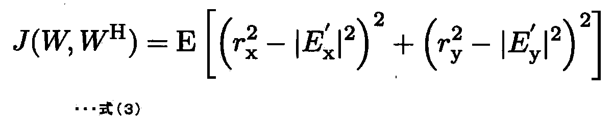
- Update filter coefficients For example, the filter coefficient updating units 23a and 23b may output the first output signal E as shown in the following equation (3). x Error signal J x And the second output signal E y Error signal J y Sum J (W, W H ) May be used as an error function. Then, the filter coefficient update units 23a and 23b apply the error function shown in Expression (3) as the error function in the update expression shown in Expression (2).
- the filter coefficient updating units 23a and 23b do not use the relationship between the elements of the characteristic matrix obtained by the unitary nature of the optical transmission path, the following is obtained.
- the filter coefficient updating unit 23a receives the error signal J x And J y Even if you try to make the sum of x Filter coefficient w to reduce only xx And w yx Will be updated.
- the filter coefficient update unit 23b also receives the error signal J.
- the filter coefficient updating units 23a and 23b update each filter coefficient using the relationship between the elements of the characteristic matrix obtained by the unitary nature of the optical transmission path.
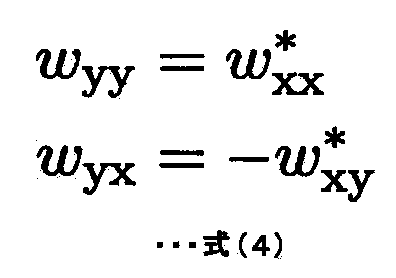
- the following expression (4) is a relational expression that is established between the elements of the Jones matrix W obtained by unitary property in an ideal optical transmission line in which the above-described PDL does not exist.
- the following equation (5) shows an example of a filter coefficient update equation using the relationship between the elements of the characteristic matrix obtained by the unitary nature of the optical transmission path.
- Formula (5) is an update formula obtained by applying the error function shown in Formula (3) and the relational expression between elements shown in Formula (4) to the update formula of Formula (2).
- the filter coefficient update units 23a and 23b operate as follows by using the update equation shown in Equation (5). That is, all the elements of the Jones matrix W as the filter coefficients of the filter units 21a to 21d are converted into the first output signal E.
- the polarization separation device 2 starts the following operation when the first and second input signals detected from the received optical signal are input to the coherent optical receiver provided with the polarization separation device 2.
- the filter unit 21a receives 11 components w of Jones matrix as the first input signal. xx Is filtered as a filter coefficient.
- the filter unit 21c receives the 21 component w of the Jones matrix as the second input signal. yx Is filtered as a filter coefficient.
- the adder 22a adds the outputs of the filter units 21a and 21c and outputs the result as a first output signal.
- the filter unit 21b receives the 12 components w of the Jones matrix as the first input signal. xy Is filtered as a filter coefficient.
- the filter unit 21d receives the 22 component w of the Jones matrix as the second input signal. yy Is filtered as a filter coefficient.
- the adder 22b adds the outputs of the filter units 21b and 21d and outputs the result as a second output signal.
- the filter coefficient updating unit 23a uses a relational expression between elements of the characteristic matrix obtained by unitary property. Thus, the filter coefficients of the filter units 21a and 21c are updated so that the sum of the error signals with respect to the first and second output signals is made smaller.
- the filter coefficient updating unit 23a updates each corresponding filter coefficient using the update expression shown in Expression (5).
- the filter coefficient updating unit 23b uses the relationship between the elements of the characteristic matrix obtained by the unitary property.
- the filter coefficients of the filter units 21b and 21d are updated so that the sum of the error signals with respect to the first and second output signals is made smaller.
- the filter coefficient updating unit 23b updates each corresponding filter coefficient using the update expression shown in Expression (5).
- the polarization separation device 2 adaptively updates and converges the filter coefficients of the filter units 21a to 21d.
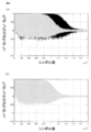
- 3A and 3B are diagrams of simulations of polarization separation processing using the polarization separation device 94 of the related technique shown in FIG. 5 and the polarization separation device 2 as the second embodiment, respectively.
- 3 (a) and 3 (b) show the error function J x And J y It is the graph which showed the time change of the value of.
- the vertical axis is not the value of the error function itself, but r x 2 ⁇
- the horizontal axis represents the number of symbols subjected to polarization separation processing.
- 2 Gray line
- 2 Black line
- the polarization separation device 2 as the second embodiment of the present invention estimates each filter coefficient in a shorter time than the polarization separation device 94 of the related art.
- the polarization separation device as the second exemplary embodiment of the present invention can separate an optical signal obtained by polarization-multiplexing two independent optical signals at higher speed and with higher accuracy. The reason is that the first and second filter coefficient update units use the relationship between the elements of the characteristic matrix obtained by the unitary nature of the optical transmission path.
- the filter coefficients are adaptively updated so that both error signals of the output signals reproduced from the first and second filter units are made smaller. Therefore, the polarization separation device as the second exemplary embodiment of the present invention can reduce the time required for the filter coefficients to converge. Also, the related art polarization separation processing has a problem that it may not converge to the correct filter coefficient. Further, in the polarization separation processing of the related art, there is a problem that only an electric signal corresponding to one of the two independent optical signals may be output instead of the two independent optical signals. In other words, the related art polarization separation processing has a problem that two independent optical signals may not be correctly separated.
- the polarization separation device 2 as the second embodiment of the present invention can separate two independent optical signals with higher accuracy.
- the filter coefficient updating units 23a and 23b have two expressions representing the relationship obtained by the unitary nature of the optical transmission path shown in Equation (4) as the relationship between the elements of the characteristic matrix. Only one of them may be used. Further, the relational expression between the elements of the characteristic matrix used by the filter coefficient updating units 23a and 23b is not limited to the relation obtained by unitary property. If the characteristics of the optical transmission line are specified, a relational expression existing between elements of the matrix representing the inverse characteristics can be derived. (Third embodiment) Next, a third embodiment of the present invention will be described in detail with reference to the drawings. In the second embodiment of the present invention, an example has been described in which it is assumed that no PDL exists in the optical transmission line.
- the polarization separation device 3 as the third embodiment of the present invention includes the same configuration as the polarization separation device 2 as the second embodiment of the present invention described with reference to FIG.
- the filter coefficient update expressions used by the filter coefficient update units 23a and 23b are different.
- the filter coefficient updating units 23a and 23b in the third embodiment of the present invention operate as follows using the relational expression between the elements of the characteristic matrix obtained by the unitary property.
- the filter coefficient updating unit updates each filter coefficient so as to make the linear sum of each error signal with respect to the first and second output signals smaller.
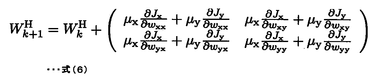
- the filter coefficient updating units 23a and 23b in the third embodiment of the present invention update each filter coefficient using the update expression shown in the following expression (6).
- ⁇ x And ⁇ y Is a parameter for adjusting the influence of the error signal of each output signal.
- the operation of the polarization separation device 3 configured as described above is the same as that of the second embodiment of the present invention except that the filter coefficient updating units 23a and 23b use Expression (6) instead of Expression (5).
- the operation is the same as that of the polarization separation device 2 as a form.
- the polarization separation apparatus can separate an optical signal obtained by polarization-multiplexing two independent optical signals at higher speed and with higher accuracy even in the presence of PDL. .
- the reason is as follows.
- the first and second filter coefficient update units use the relational expression between the elements of the characteristic matrix obtained by the unitary property to reduce the linear sum of the error signal of the output signal reproduced from each filter unit. This is because the coefficient is updated.
- the relational expression between the elements of the characteristic matrix obtained by the unitary property is established to some extent if the PDL is small. Therefore, the linear sum of each error signal is used as an error function while using the relational expression between the elements of the characteristic matrix obtained by the unitary property.
- the polarization separation device as the third exemplary embodiment of the present invention can remove the influence of PDL to some extent.
- the filter coefficient updating units 23a and 23b are not limited to the linear sum of the error functions of the first and second output signals, but perform the non-linear sum of the square of each error signal, the square root, or the exponential function of the error function. It may be used as an error function. (Fourth embodiment) Next, a fourth embodiment of the present invention will be described in detail with reference to the drawings.
- the polarization separation device provided in the coherent optical receiver that receives an optical signal in which two independent optical signals are polarization multiplexed has been described.
- an optical communication system using the optical digital coherent communication system an optical communication system that does not use the polarization multiplexing system, that is, uses a single-polarized optical signal (hereinafter referred to as a single polarization system) is also conceivable.
- Providing a dedicated digital signal processor for each of these optical communication systems raises the problem of increased device costs. Therefore, it is desirable that the polarization separation device mounted on the digital signal processor is compatible with both the single polarization method and the polarization multiplexing method.
- the polarization separation device 4 as the fourth embodiment of the present invention includes the same functional blocks as the polarization separation device 2 according to the second embodiment of the present invention described with reference to FIG.
- the filter coefficient update expressions used by the filter coefficient update units 23a and 23b are different.
- the filter coefficient updating units 23a and 23b in the fourth embodiment of the present invention are expressed as r in equation (5). x And r y Each filter coefficient is updated using a filter coefficient update formula in which one of the values is set to 0.
- the polarization separation device 4 as the fourth exemplary embodiment of the present invention regenerates an electrical signal corresponding to the transmitted optical signal from either the first output signal or the second output signal.
- the polarization separation device according to the fourth embodiment of the present invention can be applied to an optical communication system using either the polarization multiplexing method or the single polarization method.
- the polarization separation device as each embodiment may include either the first or second filter coefficient update unit in the present invention.
- the polarization separation device as each embodiment may update the coefficients of the other filter units using, for example, a filter coefficient update unit of related technology as shown in FIG.
- at least one filter coefficient update unit updates the filter coefficient so as to reduce both error signals of the output signals from the filter units. Therefore, the speed at which both error signals are reduced can be improved over that of the related art.
- the description has been made assuming that the number of filter taps applied to each filter unit is 1. However, the first and second filter units of the present invention are described. A filter having two or more taps can also be applied.
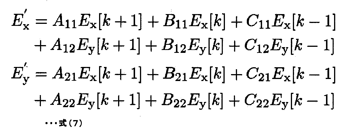
- the components of each Jones matrix are A ij , B ij , C ij far.
- E which is the amplitude of the first and second output signals x 'And E y 'Is the input signal E x [K]
- E y Using [k] and Jones matrix it is expressed as the following equation (7).
- k represents time.
- the polarization separation device as each embodiment can update the filter coefficient in substantially the same manner as when the number of taps is one.
- the present invention can be implemented.
- a dedicated communication device is assumed, but the following may be used. That is, for example, a personal computer device that performs various data processing is loaded with a board or card that performs processing corresponding to the present embodiment, and the processing is executed on the computer device side. In this way, the software that executes the processing may be installed in the personal computer device, and the processing corresponding to the present embodiment may be executed.
- the program installed in the data processing device such as the personal computer device may be distributed via various recording (storage) media such as an optical disk and a memory card. Or you may distribute via communication means, such as the internet. Further, each of the above embodiments can be combined with other embodiments.
- the present invention has been described above with reference to the embodiments, but the present invention is not limited to the above embodiments. Various changes that can be understood by those skilled in the art can be made to the configuration and details of the present invention within the scope of the present invention. This application claims priority based on Japanese Patent Application No. 2011-019908 filed on Feb. 1, 2011, the entire disclosure of which is incorporated herein. Some or all of the above embodiments can be described as in the following supplementary notes, but are not limited thereto.
- First filter coefficient updating means for repeatedly updating and converging the filter coefficients of the first filter means
- An optical receiver that performs polarization separation processing of the optical signal using a polarization separation device having the following.
- the polarization separator uses the relationship between the element of the characteristic matrix and the different element to increase the magnitude of both the error signal for each of the first output signal and the second output signal.
- At least one of the first and second filter coefficient updating means applies the relationship obtained by the unitary nature of the optical transmission line as the relationship between the elements of the characteristic matrix, thereby the filter
- At least one of the first and second filter coefficient update means is configured to reduce the linear sum of the error signal with respect to each of the first output signal and the second output signal.
- (Appendix 5) 4 The optical receiver according to appendix 3, wherein at least one of the first and second filter coefficient updating means updates the filter coefficient based on Expression (5).
- the first filter means When the optical signal received by the optical receiver is an optical signal in which two independent optical signals having orthogonal polarization states and the same carrier optical frequency are polarization multiplexed, The first filter means outputs a signal corresponding to one of the two independent optical signals as the first output signal, The second filter means outputs the signal corresponding to the other of the two independent optical signals as the second output signal, according to any one of appendix 1 to appendix 5, Optical receiver. (Appendix 7) When the optical signal received by the optical receiver is a single polarization optical signal, The first and second filter coefficient updating means are configured to output the first filter signal based on an error signal that expects a value of one of the first output signal and the second output signal to be zero.
- each filter coefficient of the second filter means is updated.
- Appendix 8 A polarization separation device used in an optical receiver that receives an optical signal via an optical transmission line, Each signal obtained by filtering the first input signal and the second input signal detected from the optical signal by the optical receiver, using an element of a characteristic matrix representing an inverse characteristic of the optical transmission path as a filter coefficient
- Two filter means Using the relationship between the elements of the characteristic matrix and the different elements, the magnitudes of both error signals representing errors with respect to target values of the first output signal and the second output signal are made smaller.
- First filter coefficient updating means for repeatedly updating and converging the filter coefficients of the first filter means,
- a polarized light separation device (Appendix 9) Using the relationship between the elements of the characteristic matrix and the different elements, the first output signal and the second output signal, respectively, so that the magnitude of both the error signal is smaller.
- the polarization separation apparatus according to appendix 8 further comprising second filter coefficient update means for repeatedly updating and converging the filter coefficients of the second filter means.
- a polarization separation method for a received optical signal For each of the first input signal and the second input signal detected from the received optical signal, an element of a characteristic matrix that represents an inverse characteristic of the optical transmission line on which the received optical signal is received is a first filter coefficient. Using each signal filtered as a first output signal, For each of the first input signal and the second input signal, a second output signal is obtained by using each signal obtained by filtering an element different from the element of the characteristic matrix as a second filter coefficient. Output, Update the first filter coefficient to reduce the magnitude of both the error signal for the first and second output signals using the relationship between the elements of the characteristic matrix and the different elements To converge by A polarization separation method characterized by the above.
- the second filter coefficient is used to further reduce the magnitude of both error signals for the first and second output signals using the relationship between the elements of the characteristic matrix and the different elements.
- the present invention relates to an optical receiver, a polarization separation device, and a polarization separation method in a polarization demultiplexing optical communication system, and has industrial applicability.
- Optical receiver 91 90-degree hybrid 92a, 92b, 92c, 92d
- Optical carrier frequency deviation / optical phase deviation compensation unit 96a, 96b Symbol identification unit 901a, 901b, 901c, 901d Filter unit 902a, 902b Filter coefficient update unit
Abstract
Description
光位相変調方式は、従来の光強度変調方式のように送信レーザ光の光強度に対してデータ変調を行うのではなく、送信レーザ光の位相に対してデータ変調を行う方式である。光位相変調方式としては、QPSK(Quadrature Phase Shift Keying)や8PSK(8Phase Shift Keying)、QAM(Quadrature Amplitude Modulation)などの方式が知られている。これらのデータ変調を採用した光位相変調方式では、1シンボルに対して複数のビットを割り当てることにより、シンボルレート(ボーレート)を低下させることが可能である。このため、光位相変調方式は、電気デバイスの動作速度を低減できる。また、その結果、光位相変調方式では、装置の製造コストの削減が期待できる。例えば、QPSKを用いる場合、4個の光位相(例えば45度、135度、225度、315度)に対して、それぞれ2ビット(例えば00、01、11、10)を割り当てる。このため、QPSKのシンボルレートは、光強度変調方式のシンボルレート(すなわちビットレート)の1/2に低減可能である。
光位相変調された信号光を受信するためには、光コヒーレント方式を用いる。これは、信号光と、信号光とほぼ同一の周波数を有するレーザ光(局部発振光と呼ばれる)とを、90度ハイブリッドと呼ばれる光学素子により結合した上で、その出力を光検出器により受光する方式である。ここで、説明を簡単にするため、信号光と局部発振光との偏光状態は同一の直線偏光であると仮定する。光コヒーレント方式を用いた場合、光検出器から出力される電気信号の交流成分は、信号光および局部発振光のビート信号である。そして、その振幅は、信号光および局部発振光の光強度に比例する。また、その位相は、信号光の搬送波周波数および局部発振光の周波数が同一であれば、信号光および局部発振光の位相の差となる。局部発振光の位相が送信端の光変調器に入力されるレーザ光の位相と同一であれば、ビート信号の位相が、送信端でレーザ光に付与された位相である。このため、シンボルマッピングを用いてビート信号の位相をビット列に変換することにより、送信データを復調することが可能である。
実際には、信号光の搬送波周波数および局部発振光の周波数の値は完全には一致しない。さらに、光受信器における局部発振光の位相と、光送信器において光変調器に入力されるレーザ光との位相も一致しない。したがって、光送信器において光変調器に入力される信号光と局部発振光との位相差である光位相偏差、および信号光の搬送波周波数と局部発振光の周波数との差である光搬送波周波数偏差による影響を補償する必要がある。なお光位相偏差および光搬送波周波数偏差を補償する具体的な方法については本発明の説明に特に必要ではないため説明を省略する。
一方、偏光多重分離技術も、超高速光通信システムを実現する技術の1つとして注目されている。偏光多重分離技術では、光送信器は、搬送波が同一の周波数帯に配備され、かつ、偏光状態が互いに直交する2個の独立した光信号を多重して送信する。また、光受信器は、受信信号から前述の2個の独立した光信号を分離する。これにより、偏光多重分離技術は、2倍の伝送速度を実現する。逆に、偏光多重分離技術は、光信号のシンボルレート(ボーレート)を1/2にすることができるため、電気デバイスの動作速度を低減して装置コストを削減可能であるとも言い換えることができる。
上述した光位相変調方式および偏光多重分離技術の両方を組み合わせることにより、100Gbpsというような超高速光通信システムを実現することができる。光搬送波周波数偏差および光位相偏差を補償する処理、および、2個の独立した光信号に分離する処理(偏光分離処理)は、LSI(Large Scale Integration)などにより実装されるディジタル信号処理回路によって実現可能である。このようなディジタル信号処理回路を用いて送信データを高精度に復調する技術は、光ディジタルコヒーレント通信方式と呼ばれる。
以降では、光ディジタルコヒーレント通信方式を用いた超高速光通信システムにおける受信処理について図面を参照して説明する。
図4は、光ディジタルコヒーレント通信方式を用いた光通信システムにおける関連技術の光受信器90の構成を示すブロック図である。光受信器90は、光伝送路から受信した光信号を、受信光信号の搬送波周波数とほぼ同一の周波数を有する局部発振光とともに、90度ハイブリッド91に入力する。90度ハイブリッド91は、直交する2つの偏光軸それぞれに対して平行な偏光状態を有する光信号の実部成分および虚部成分の合計4個の光信号を出力する。これら4個の光信号は、光ディテクタ92a~92dによりアナログ電気信号に変換された後、アナログディジタルコンバータ(以降ADCと記載する)93a~93dによりディジタル電気信号に変換される。これらのディジタル電気信号は、不図示のリサンプリング部により受信光信号のシンボルレート(ボーレート)で標本化されたディジタル電気信号に変換された後、偏光分離装置94に入力される。偏光分離装置94は、入力された4個のディジタル電気信号を元に、偏光多重された2つの独立した光信号に対応する電気信号を抽出する。抽出された各電気信号は、光搬送波周波数偏差・光位相偏差補償部95a~95bにより、受信光信号と局部発振光との間の光搬送波周波数偏差と光位相偏差による光位相回転がそれぞれ補償される。その後、各電気信号は、シンボル識別部96a~96bによりそれぞれ元の送信ビット列に復調される。
以上に説明したように、この関連技術の光受信器90は、次のように動作する。即ち、光位相変調方式および偏光多重分離技術を組み合わせた上で、偏光分離された2個の独立した光信号に対応する電気信号のそれぞれに対して、光搬送波周波数偏差および光位相偏差による影響を補償する。これにより、関連技術の光受信器90は、100Gbpsというような超高速光通信システムを実現することを可能としている。
次に、関連技術の光受信器90が備える偏光分離装置94について説明する。
図5は、偏光分離装置94の構成を示すブロック図である。偏光分離装置94は、図5に示すように、フィルタ部901a~901d、フィルタ係数更新部902a~902bを含む。なお、図5において、入力信号1は、図4における90度ハイブリッド91において直交する2つの偏光軸の一方に平行な偏光状態を有する光信号に対応する電気信号である。すなわち、この入力信号1は、図4のADC93aから出力されるディジタル電気信号を実部成分とし、ADC93bから出力されるディジタル電気信号を虚部成分とする複素数により表される。
同様に、図5の入力信号2は、図4における90度ハイブリッド91において直交する2つの偏光軸の他方に平行な偏光状態を有する光信号に対応する電気信号である。すなわち、この入力信号2は、図4のADC93cから出力されるディジタル電気信号を実部成分とし、ADC93dから出力されるディジタル電気信号を虚部成分とする複素数により表される。
図5の出力信号1および出力信号2は、それぞれ光送信器において偏光多重された2個の独立した光信号に対応する電気信号として再生される信号である。
図5のフィルタ部901a~901dは、入力信号1および入力信号2を、各フィルタ部に独立に設定されたフィルタ係数を用いてそれぞれフィルタリング処理を実施する。その後、フィルタ部901aおよびフィルタ部901cの和が、出力信号1として出力される。また、フィルタ部901bおよびフィルタ部901dの和が、出力信号2として出力される。なおフィルタ部901a~901dとしては、一般的なFIR(Finite Impulse Response)フィルタを用いることができる。
フィルタ係数更新部902aは、所定のアルゴリズムにしたがってフィルタ部901aおよび901cのフィルタ係数を更新する。同様にフィルタ係数更新部902bはフィルタ部901bおよび901dのフィルタ係数を更新する。フィルタ係数更新部902a~902bが各フィルタ係数を更新するためのアルゴリズムとしては、CMA(Constant Modulus Algorithm)が広く用いられている。CMAは、抽出された電気信号の包絡線が一定、すなわち強度が一定となるように、フィルタ部901a~901dの各フィルタ係数を適応的に制御することにより偏光分離を行うアルゴリズムである。その他、各フィルタ部のフィルタ係数を更新するアルゴリズムとしては、LMS(Least Mean Square)アルゴリズムも一般的である(非特許文献1参照)が、ここでは、CMAを用いる例について説明する。
次式(1)に、CMAで定義される誤差関数の一例を示す。
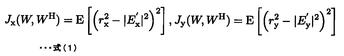
なお、ここでは、説明を簡単にするためフィルタ部のタップ数を1としたが、タップ数を2以上としても良い。また、rxおよびryは、それぞれ出力信号1および出力信号2の振幅の目標値である。また、Ex’およびEy’は、それぞれ出力信号1および出力信号2の振幅である。また、E[x]は、xの期待値を表す。
フィルタ係数更新部902aは、Jxが最小となるようにフィルタ部901aおよび901cの各フィルタ係数を逐次更新する。また、フィルタ係数更新部902bは、Jyが最小となるように、フィルタ部901bおよび901dの各フィルタ係数を逐次更新する。
次式(2)に、式(1)のCMAの誤差関数に基づいてフィルタ係数更新部902aおよび902bがフィルタ係数を更新するための更新式を示す。

式(1)は偏波多重QPSK信号の偏光分離に一般的に用いられる誤差関数であり、Exが半径rxの円上にあるときJxは0となり、同様にEyが半径ryの円上にあるときJyは0となる。誤差関数Jx及びJyが0の条件は偏波分離が成功するための必要十分条件であるため、CMAは誤差関数Jx及びJyが0となるようにフィルタ係数を更新することにより、偏光分離が可能となる。
なお、式(1)に示す以外にも、ExまたはEyがQPSKの4個のシンボルのいずれかにあるときに0となるような誤差関数も提案されており、decision−directed方式と呼ばれる。本方式は、QPSKについては式(1)と本質的には同一であるため、実装が容易な式(1)が使用されるのが一般的であるものの、式(1)が適用できない16QAMなどの多値数の大きい位相変調方式にも適用可能であるという長所がある。
以上に述べたように、偏光分離装置94のフィルタ部901a~901d、CMAを用いたフィルタ係数更新部902aおよび902bの動作により、受信光信号から2個の独立した光信号に対応する電気信号を分離・抽出することが可能となる。このような、偏光分離装置におけるフィルタ係数更新処理については、特許文献1にも記載されている。また、再生される各出力信号に基づいて偏光分離処理を行う他の装置が、非特許文献2にも記載されている。
(発明の目的)
本発明の目的は、上述の課題を鑑みてなされたものであって、受信光信号の偏光分離処理で用いるフィルタ係数をより高速に収束させる偏光分離装置およびこれを備えた光受信器を提供することを目的とする。
また、本発明の偏光分離装置は、光伝送路を介して光信号を受信する光受信器で用いられる偏光分離装置であって、前記光受信器によって前記光信号から検出される第1の入力信号および第2の入力信号それぞれに対して、前記光伝送路の逆特性を表す特性行列の要素をフィルタ係数としてフィルタリング処理した各信号を用いて、第1の出力信号を出力する第1のフィルタ手段と、前記第1の入力信号および前記第2の入力信号それぞれに対して、前記特性行列の前記要素とは異なる要素をフィルタ係数としてフィルタリング処理した各信号を用いて、第2の出力信号を出力する第2のフィルタ手段と、前記特性行列の要素と前記異なる要素との間の関係を用いて、前記第1の出力信号および前記第2の出力信号それぞれの目標値に対する誤差を表す誤差信号の両方の大きさをより小さくするよう、前記第1のフィルタ手段のフィルタ係数を繰り返し更新して収束させる第1のフィルタ係数更新手段と、を備える。
また、本発明の偏光分離方法は、受信光信号の偏光分離方法であって、前記受信光信号から検出される第1の入力信号および第2の入力信号それぞれに対して、前記受信光信号が受信された光伝送路の逆特性を表す特性行列の要素を第1のフィルタ係数としてフィルタリング処理した各信号を用いて、第1の出力信号を出力し、前記第1の入力信号および前記第2の入力信号それぞれに対して、前記特性行列の前記要素とは異なる要素を第2のフィルタ係数としてフィルタリング処理した各信号を用いて、第2の出力信号を出力し、前記特性行列の要素と前記異なる要素との間の関係を用いて、前記第1および前記第2の出力信号に対する誤差信号の両方の大きさをより小さくするよう前記第1のフィルタ係数を更新することにより収束させる。
(第1の実施の形態)
本発明の第1の実施の形態としての偏光分離装置1の機能ブロック構成を図1に示す。図1において、偏光分離装置1は、第1のフィルタ部11と、第2のフィルタ部12と、第1のフィルタ係数更新部13と、第2のフィルタ係数更新部14とを備えている。
ここで、偏光分離装置1は、コヒーレント光受信器に備えられている。偏光分離装置1を備えるコヒーレント光受信器は、光伝送路を介して光信号を受信する。この光信号は、光送信器において、偏光状態が直交し、かつ、搬送波光周波数が同一である2個の独立した光信号が偏光多重されて送信されたものであってもよい。また、このコヒーレント光受信器は、受信した光信号から、第1の入力信号および第2の入力信号を検出し、偏光分離装置1に入力する。
例えば、このコヒーレント光受信器は、図4に示した関連技術のコヒーレント受信器90と同様の動作を行うものでも良い。即ち、コヒーレント光受信器が受信した光信号およびその搬送波周波数とほぼ同一の周波数を有する局部発振光を90度ハイブリッドに入力後AD変換することにより、第1の入力信号および第2の入力信号を検出してもよい。この場合、前述のように、第1の入力信号は、直交する2つの偏光軸の一方に平行な偏光状態を有する光信号に対応する電気信号となる。同様に、第2の入力信号は、直交する2つの偏光軸の他方に平行な偏光状態を有する光信号に対応する電気信号となる。
第1のフィルタ部11は、第1の入力信号および第2の入力信号のそれぞれに対して、光伝送路の逆特性を表す特性行列の要素をフィルタ係数としてフィルタリング処理した各信号を用いて、第1の出力信号を出力する。例えば、第1のフィルタ部11は、第1の入力信号および第2の入力信号をそれぞれ上述のようにフィルタリング処理した各信号の和を第1の出力信号として出力してもよい。なお、コヒーレント光受信器によって受信された光信号が、光送信器において2個の独立した光信号が偏光多重された信号であった場合、第1のフィルタ部11は次のように動作する。即ち第1のフィルタ部11は2個の独立した光信号のうちの一方に対応する電気信号を第1の出力信号として再生する。
ここで、光伝送路の逆特性を表す特性行列について説明する。光伝送路の特性は、行列で表すことができる。すなわち、この行列は、光伝送路への入力信号と光伝送路からの出力信号とを結びつける行列である。より具体的には、光伝送路への入力信号に「光伝送路の特性を表す行列」をかけると光伝送路からの出力信号となる。さらに、光伝送路の逆特性を表す特性行列は、このような光伝送路の特性を表す行列の逆関数(狭義には、逆行列)を表す。すなわち、光伝送路からの出力信号に、特性行列をかけると光伝送路への入力信号が得られることになる。
第2のフィルタ部12は、第1の入力信号および前記第2の入力信号のそれぞれに対して、以下のように動作する。即ち第2のフィルタ部12は、特性行列の要素のうち、第1のフィルタ部11が用いる要素とは異なる要素をフィルタ係数としてフィルタリング処理した各信号を用いて、第2の出力信号を出力する。例えば、第2のフィルタ部12は、第1の入力信号および第2の入力信号をそれぞれ上述のようにフィルタリング処理した各信号の和を第2の出力信号として出力してもよい。なお、コヒーレント光受信器によって受信された光信号が、光送信器において2個の独立した光信号が偏光多重された信号であった場合、第2のフィルタ部12は、以下のように動作する。即ち第2のフィルタ部12は、2個の独立した光信号のうちの他の一方に対応する電気信号を第2の出力信号として再生する。
第1のフィルタ係数更新部13は、特性行列において第1のフィルタ部11で用いられる要素と第2のフィルタ部12で用いられる要素との間に存在する関係を用いて、以下のように動作する。即ち第1のフィルタ部11および第2のフィルタ部12からそれぞれ再生された各出力信号に対する誤差信号の両方の大きさをより小さくするよう第1のフィルタ部11のフィルタ係数を適応的に更新する。すなわち、第1のフィルタ係数更新部13は、この更新処理を繰り返すことにより、各出力信号に対する誤差信号の両方の大きさがほぼ最小となるまで第1のフィルタ部11のフィルタ係数を収束させる。
第2のフィルタ係数更新部14は、特性行列の要素間に存在する前述の関係を用いて以下のように動作する。即ち第1のフィルタ部11および第2のフィルタ部12からそれぞれ再生された各出力信号に対する誤差信号の両方の大きさをより小さくするよう第2のフィルタ部12のフィルタ係数を適応的に更新する。すなわち、第2のフィルタ係数更新部14は、この更新処理を繰り返すことにより、各出力信号に対する誤差信号の両方の大きさがほぼ最小となるまで第2のフィルタ部12のフィルタ係数を収束させる。
なお、第1のフィルタ係数更新部13および第2のフィルタ係数更新部14は、第1のフィルタ部11および第2のフィルタ部12からそれぞれ再生される各出力信号の誤差信号を、例えば次のように算出する。即ち前述のCMAで定義された式(1)、あるいは、非特許文献1または非特許文献2において定義されている関数などを用いて誤差信号を、算出すればよい。
ここで第1のフィルタ係数更新部13および第2のフィルタ係数更新部14が特性行列の要素間の関係を用いない場合は以下の通りである。即ち、第1のフィルタ部11が用いるフィルタ係数は第2のフィルタ部12から出力される第2の出力信号と無関係である。同様に、第2のフィルタ部12が用いるフィルタ係数は、第1のフィルタ部11から出力される第1の出力信号と無関係である。このため、第1のフィルタ係数更新部13が、第1のフィルタ部11で用いるフィルタ係数を更新することにより小さくすることができるのは、第1の出力信号に対する誤差信号のみである。同様に、第2のフィルタ係数更新部14も、第2のフィルタ部12で用いるフィルタ係数を更新することにより小さくすることができるのは、第2の出力信号に対する誤差信号のみである。
そこで、第1のフィルタ係数更新部13および第2のフィルタ係数更新部14は、特性行列の要素間の関係を用いて、各フィルタ係数を更新する。
このような特性行列の要素間に存在する関係を用いれば、以下の関係が導出される。即ち特性行列の所定の要素を適用した第1のフィルタ部11のフィルタ係数と、特性行列の他の所定の要素をフィルタ係数として適用した第2のフィルタ部12のフィルタ係数との関係が導出される。これにより、第1のフィルタ部11が用いるフィルタ係数は、第2のフィルタ部12から出力される第2の出力信号との関連性を有する。同様に、第2のフィルタ部12が用いるフィルタ係数は、第1のフィルタ部11から出力される第1の出力信号との関連性を有することになる。したがって、第1のフィルタ係数更新部13は、第1のフィルタ部11のフィルタ係数を、第1の出力信号および第2の出力信号の各誤差信号の両方をより小さくするように更新することが可能となる。同様に、第2のフィルタ係数更新部14は、第2のフィルタ部12のフィルタ係数を、第1の出力信号および第2の出力信号の各誤差信号の両方をより小さくするように更新することが可能となる。
なお、光伝送路の特性が特定されることにより、特性行列の要素間の関係は導出可能である。例えば、偏光依存性損失(Polarization Dependent Loss;PDL)が存在しない理想的な光伝送路においては、光伝送路のユニタリー性により特性行列の要素間に成立する関係式が導出される。
以上のように構成された偏光分離装置1の動作について説明する。なお、偏光分離装置1は、偏光分離装置1が備えられるコヒーレント光受信器において、受信された光信号から検出される第1および第2の入力信号が入力されると、以下の動作を開始するものとする。
まず、第1のフィルタ部11は、第1の入力信号および第2の入力信号に対して、光伝送路の逆特性を表す特性行列の所定の異なる要素をそれぞれフィルタ係数としてフィルタリング処理を実施する。そして、第1のフィルタ部11は、フィルタリング処理を実施した後の各信号を用いて、例えばその和を第1の出力信号として出力する。
また、第2のフィルタ部12は、第1の入力信号および第2の入力信号に対して、光伝送路の逆特性を表す特性行列の他の所定の異なる要素をそれぞれフィルタ係数としてフィルタリング処理する。そして、第2のフィルタ部12は、フィルタリング処理を実施した後の各信号を用いて、例えばその和を第2の出力信号として出力する。
次に、第1のフィルタ係数更新部13は、特性行列の要素間の関係を用いて、以下のように動作する。即ち、第1のフィルタ部11および第2のフィルタ部12からそれぞれ再生された各出力信号に対する誤差信号の両方の大きさをより小さくするよう第1のフィルタ部11のフィルタ係数を更新する。
また、第2のフィルタ係数更新部14は、特性行列の要素間の関係を用いて以下のように動作する。即ち、第1のフィルタ部11および第2のフィルタ部12からそれぞれ再生された各出力信号に対する誤差信号の両方の大きさをより小さくするよう第2のフィルタ部12のフィルタ係数を更新する。
以上の動作を繰り返すことにより、偏光分離装置1は、第1のフィルタ部11および第2のフィルタ部12のフィルタ係数を適応的に更新し、収束させる。
以上に説明したように、本発明の第1の実施の形態としての偏光分離装置は、受信光信号の偏光分離処理に用いるフィルタ係数をより高速に収束させることができる。
その理由について説明する。関連技術の偏光分離装置は、第1のフィルタ部から再生される出力信号の誤差関数のみに基づいて第1のフィルタ部のフィルタ係数を更新していた。また、関連技術の偏光分離装置は、第2のフィルタ部から再生される出力信号の誤差関数のみに基づいて第2のフィルタ部のフィルタ係数を更新していた。これに対して、本発明の第1の実施の形態としての偏光分離装置では、第1および第2のフィルタ係数更新部が、特性行列の要素間の関係を用いる。このことにより、第1および第2のフィルタ部から再生される各光信号の誤差信号の両方をより小さくするよう各フィルタ係数をそれぞれ適応的に更新している。したがって、本発明の第1の実施の形態としての偏光分離装置は、関連技術に比べて、各フィルタ係数が収束するまでに要する時間を短縮することができる。
(第2の実施の形態)
本発明の第2の実施の形態としての偏光分離装置2の構成を図2に示す。図2において、偏光分離装置2は、フィルタ部21a~21dと、加算器22a~22bと、フィルタ係数更新部23a~23bとを備えている。なお、フィルタ部21a、21cおよび加算器22aは、本発明の第1のフィルタ部の一実施形態を構成する。また、フィルタ部21b、21dおよび加算器22bは、本発明の第2のフィルタ部の一実施形態を構成する。また、フィルタ係数更新部23aおよび23bは、本発明の第1および第2のフィルタ係数更新部の一実施形態をそれぞれ構成する。
また、偏光分離装置2は、本発明の第1の実施の形態としての偏光分離装置1が備えられるコヒーレント光受信器と同様なコヒーレント光受信器に備えられている。なお、本実施の形態では、偏光分離装置2が備えられるコヒーレント光受信器は、光送信器において2個の独立した光信号が偏光多重されて送信された光信号を受信するものとする。偏光分離装置2には、コヒーレント光受信器において受信された光信号から検出された第1および第2の入力信号が入力される。
図2において、フィルタ部21a~21dは、FIRフィルタによって構成可能である。以下、フィルタ部21a~21dを構成するFIRフィルタのタップ数が1である場合について説明する。
フィルタ部21aは、第1の入力信号に対して、Jones行列の11成分wxxをフィルタ係数として、フィルタリング処理を実施する。フィルタ部21cは、第2の入力信号に対して、Jones行列の21成分wyxをフィルタ係数として、フィルタリング処理を実施する。加算器22aは、フィルタ部21aおよびフィルタ部21cの出力信号の和を第1の出力信号として出力する。これにより、フィルタ部21a、21cおよび加算器22aによって構成される本発明の第1のフィルタ部は、以下のように動作する。即ち、第1の入力信号および第2の入力信号をフィルタリング処理した各信号を用いて、前述の2個の独立した光信号の一方に対応する電気信号を第1の出力信号として出力する。
フィルタ部21bは、第1の入力信号に対して、Jones行列の12成分wxyをフィルタ係数として、フィルタリング処理を実施する。フィルタ部21dは、第2の入力信号に対して、Jones行列の22成分wyyをフィルタ係数として、フィルタリング処理を実施する。加算器22bは、フィルタ部21bおよびフィルタ部21dの出力信号の和を第2の出力信号として出力する。これにより、フィルタ部21b、21dおよび加算器22bによって構成される本実施の形態の第2のフィルタ部は、以下のように動作する。即ち第1の入力信号および第2の入力信号をフィルタリング処理した各信号を用いて、前述の2個の独立した光信号の他方に対応する電気信号を第2の出力信号として出力する。
フィルタ係数更新部23aは、光伝送路のユニタリー性により得られる特性行列の要素間の関係を用いて、以下のように動作する。即ち、第1の出力信号と第2の出力信号の両方の各誤差信号をより小さくするよう、フィルタ部21aおよび21cのフィルタ係数を更新する。同様に、フィルタ係数更新部23bは、光伝送路のユニタリー性により得られる特性行列の要素間の関係を用いて、以下のように動作する。即ち、第1の出力信号と第2の出力信号の両方の各誤差信号をより小さくするよう、フィルタ部21bおよび21dのフィルタ係数を更新する。
具体的には、フィルタ係数更新部23aおよび23bは、第1の出力信号の誤差信号および第2の出力信号の誤差信号の両方に基づいて算出される誤差関数の値をより小さくするよう、各フィルタ係数を更新する。例えば、フィルタ係数更新部23aおよび23bは、次式(3)に示すように、第1の出力信号Ex’の誤差信号Jxおよび第2の出力信号Ey’の誤差信号Jyの和J(W,WH)を誤差関数として用いてもよい。
ここで、フィルタ係数更新部23aおよび23bが光伝送路のユニタリー性により得られる特性行列の要素間の関係を用いない場合は以下の通りとなる。即ち第1のフィルタ部11に含まれるフィルタ部21aのフィルタ係数wxxおよびフィルタ部21cのフィルタ係数wyxは、第2のフィルタ部12から出力される第2の出力信号と無関係である。同様に、第2のフィルタ部12に含まれるフィルタ部21bのフィルタ係数wxyおよびフィルタ部21dのフィルタ係数wyyは、第1のフィルタ部11から出力される第1の出力信号と無関係である。このため、フィルタ係数更新部23aは、誤差信号JxおよびJyの和をより小さくしようとしても、結局のところ、誤差信号Jxのみを小さくするようフィルタ係数wxxおよびwyxを更新してしまう。同様に、フィルタ係数更新部23bも、誤差信号JxおよびJyの和をより小さくしようとしても、結局のところ、誤差信号Jyのみを小さくするようフィルタ係数wxyおよびwyyを更新してしまう。すなわち、光伝送路のユニタリー性により得られる特性行列の要素間の関係を用いない場合は以下の通りとなる。即ち、フィルタ係数更新部23aおよび23bが行う更新処理は、式(2)に式(3)に示した誤差関数を適用しても、式(2)の更新式を用いるのと同等になってしまう。
そこで、フィルタ係数更新部23aおよび23bは、光伝送路のユニタリー性により得られる特性行列の要素間の関係を用いて、各フィルタ係数を更新することにする。次式(4)は、前述のPDLが存在しない理想的な光伝送路において、ユニタリー性により得られるJones行列Wの要素間に成立する関係式である。

以上のように構成された偏光分離装置2の動作について説明する。なお、偏光分離装置2は、偏光分離装置2が備えられるコヒーレント光受信器において、受信された光信号から検出された第1および第2の入力信号が入力されると、以下の動作を開始するものとする。
まず、フィルタ部21aは、第1の入力信号にJones行列の11成分wxxをフィルタ係数としてフィルタリング処理する。フィルタ部21cは、第2の入力信号にJones行列の21成分wyxをフィルタ係数としてフィルタリング処理する。そして、加算器22aは、フィルタ部21aおよび21cの出力を加算して第1の出力信号として出力する。
また、フィルタ部21bは、第1の入力信号にJones行列の12成分wxyをフィルタ係数としてフィルタリング処理する。フィルタ部21dは、第2の入力信号にJones行列の22成分wyyをフィルタ係数としてフィルタリング処理する。そして、加算器22bは、フィルタ部21bおよび21dの出力を加算して第2の出力信号として出力する。
次に、フィルタ係数更新部23aは、ユニタリー性により得られる特性行列の要素間の関係式を用いる。このことにより、第1および第2の出力信号に対する誤差信号の和をより小さくするようフィルタ部21aおよび21cの各フィルタ係数を更新する。例えば、フィルタ係数更新部23aは、式(5)に示す更新式を用いて該当する各フィルタ係数を更新する。
また、フィルタ係数更新部23bは、ユニタリー性により得られる特性行列の要素間の関係を用いる。このことにより、第1および第2の出力信号に対する誤差信号の和をより小さくするようフィルタ部21bおよび21dの各フィルタ係数を更新する。例えば、フィルタ係数更新部23bは、式(5)に示す更新式を用いて該当する各フィルタ係数を更新する。
以上の動作を繰り返すことにより、偏光分離装置2は、各フィルタ部21a~21dのフィルタ係数を適応的に更新し、収束させる。
次に、本発明の第2の実施の形態としての偏光分離装置2を用いたシミュレーション結果について説明する。図3(a)および(b)は、図5に示した関連技術の偏光分離装置94および本第2の実施形態としての偏光分離装置2をそれぞれ用いた偏光分離処理のシミュレーションの図である。図3(a)および(b)は、誤差関数JxおよびJyの値の時間変化を示したグラフである。なお、図3において、縦軸は、誤差関数そのものの値ではなく、rx 2−|Ex’|2およびry 2−|Ey’|2の値を表している。これは、これらの値が、フィルタ係数更新式において必要となるためである。従って、これらの値を2乗することにより誤差関数の値となる。また、横軸は、偏光分離処理を行ったシンボル数を表している。
図3(a)および(b)において、シミュレーション開始直後からしばらくの間、rx 2−|Ex’|2(灰色線)およびry 2−|Ey’|2(黒線)の値(それぞれ誤差関数JxおよびJyに対応)の値は、ともに−0.5から1の間の値を取る。その後、rx 2−|Ex’|2およびry 2−|Ey’|2の値は、ほぼゼロの値を取るようになる。この時点で、各フィルタ係数の推定処理、すなわち偏光分離処理が完了したことが分かる。
図3(a)の関連技術のシミュレーション結果においては、Jyの値がゼロとなるまでの時間がJxと比べて大きい。したがって、関連技術の偏光分離装置94は、第2の出力信号を正しく出力するまでに多大な時間を要していることが分かる。
一方、図3(b)の本発明の第2の実施の形態のシミュレーション結果においては、rx 2−|Ex’|2およびry 2−|Ey’|2の値(即ちJxおよびJyの値)の時間変化がほぼ一致している。すなわち、本発明の第2の実施の形態では、フィルタ係数更新部23aおよび23bが、フィルタ係数の推定処理をほぼ同一のタイミングで完了していることが分かる。また、rx 2−|Ex’|2およびry 2−|Ey’|2の値(即ちJxおよびJyの値)が0になるまでの時間は、図3(b)に比べて早い。このことから、本発明の第2の実施の形態としての偏光分離装置2は、関連技術の偏光分離装置94に比べて短時間で各フィルタ係数を推定していることが分かる。
以上に説明したように、本発明の第2の実施の形態としての偏光分離装置は、2個の独立した光信号が偏光多重された光信号をより高速かつより精度よく分離することができる。
その理由は、第1および第2のフィルタ係数更新部が、光伝送路のユニタリー性により得られる特性行列の要素間の関係を用いるからである。これにより、第1および第2のフィルタ部から再生される各出力信号の誤差信号の両方をより小さくするようフィルタ係数を適応的に更新している。従って、本発明の第2の実施の形態としての偏光分離装置は、フィルタ係数が収束するまでに要する時間を短縮することができる。
また、関連技術の偏光分離処理では、正しいフィルタ係数に収束しない場合があるという課題があった。また、関連技術の偏光分離処理では、2個の独立した光信号ではなく、2個の独立した光信号のうち一方に対応する電気信号のみを出力してしまう場合があるという課題があった。即ち関連技術の偏光分離処理では、2個の独立した光信号を正しく分離することができない場合があるという課題があった。
これに対して、本発明の第2の実施の形態としての偏光分離装置2は、より精度よく2個の独立した光信号を分離することができる。
その理由について説明する。ユニタリー性により得られる特性行列の要素間の関係式が成立する場合、第1および第2の出力信号に同一の信号が出力される場合のフィルタ係数の条件はW=0となる。このことは、第1および第2の出力信号が常にゼロとなることを意味する。したがって、本発明の第2の実施の形態としての偏光分離装置は、第1および第2の出力信号として同一の信号が出力される可能性を減少させることができるからである。さらに、本発明の第2の実施の形態としての偏光分離装置は、正しくないフィルタ係数が推定される可能性を削減することができるからである。
なお、本実施の形態の説明において、フィルタ係数更新部23aおよび23bは、特性行列の要素間の関係として、式(4)に示した光伝送路のユニタリー性により得られる関係を表す2つの式のうち何れか1つのみを用いてもよい。また、フィルタ係数更新部23aおよび23bが用いる特性行列の要素間の関係式は、ユニタリー性により得られる関係に限らない。なお、光伝送路の特性が特定されれば、その逆特性を表す行列の要素間に存在する関係式は導出可能である。
(第3の実施の形態)
次に、本発明の第3の実施の形態について図面を参照して詳細に説明する。本発明の第2の実施の形態では、光伝送路にPDLが存在しないことを仮定した例について説明した。しかしながら、光伝送路中のPDLの存在は好ましくないものの、実際の光通信システムにおいては多少のPDLが存在する可能性がある。本実施の形態では、光伝送路にPDLが存在することを想定した偏光分離装置について説明する。
本発明の第3の実施の形態としての偏光分離装置3は、図2を用いて説明した本発明の第2の実施の形態としての偏光分離装置2と同一の構成を含む。ただし、フィルタ係数更新部23aおよび23bが用いるフィルタ係数の更新式が異なる。
本発明の第3の実施形態におけるフィルタ係数更新部23aおよび23bは、ユニタリー性により得られる特性行列の要素間の関係式を用いた上で次のように動作する。即ち、フィルタ係数更新部は第1および第2の出力信号に対する各誤差信号の線形和をより小さくするよう各フィルタ係数を更新する。例えば、本発明の第3の実施の形態におけるフィルタ係数更新部23aおよび23bは、次式(6)に示す更新式を用いて各フィルタ係数を更新する。
以上のように構成される偏光分離装置3の動作は、フィルタ係数更新部23aおよび23bが式(5)の代わりに式(6)を用いる点が異なる以外は、本発明の第2の実施の形態としての偏光分離装置2の動作と同様である。
次に、本発明の第3の実施の形態の効果について述べる。本発明の第3の実施の形態としての偏光分離装置は、PDLが存在する場合にも、2個の独立した光信号が偏光多重された光信号をより高速かつより精度よく分離することができる。
その理由は以下の通りである。即ち第1および第2のフィルタ係数更新部が、ユニタリー性により得られる特性行列の要素間の関係式を用いながら各フィルタ部から再生される出力信号の誤差信号の線形和をより小さくするようフィルタ係数を更新するからである。ここで、ユニタリー性により得られる特性行列の要素間の関係式は、PDLが小さければある程度成立するといえる。そこで、ユニタリー性により得られる特性行列の要素間の関係式を用いながら、各誤差信号の線形和を誤差関数として用いている。このことにより、各フィルタ係数更新部において、他方の出力信号の誤差信号の影響を小さくすることができるからである。その結果、本発明の第3の実施の形態としての偏光分離装置は、PDLの影響をある程度まで除去することが可能となるからである。
なお、フィルタ係数更新部23aおよび23bは、第1および第2の各出力信号の誤差関数の線形和に限らず、各誤差信号の自乗、2乗根あるいは誤差関数の指数関数などの非線形和を誤差関数として用いてもよい。
(第4の実施の形態)
次に、本発明の第4の実施の形態について図面を参照して詳細に説明する。本発明の第2および第3の実施の形態では、2個の独立した光信号が偏光多重された光信号を受信するコヒーレント光受信器に備えられる偏光分離装置について説明した。しかしながら、光ディジタルコヒーレント通信方式を用いる光通信システムとしては、偏光多重方式を用いない、すなわち単一偏光の光信号を用いる光通信システム(以後、単一偏光方式と記載する)も考えられる。これらの光通信システムそれぞれに対して専用のディジタル信号処理プロセッサを用意するのは装置コスト増大の問題が生じる。そのため、ディジタル信号処理プロセッサに実装する偏光分離装置は、単一偏光方式および偏光多重方式の両方に対応していることが望ましい。そこで、本実施の形態では、単一偏光方式の光通信システムにおけるコヒーレント光受信器に備えられる偏光分離装置について説明する。
本発明の第4の実施の形態としての偏光分離装置4は、図2を用いて説明した本発明の第2の実施の形態としての偏光分離装置2と同一の機能ブロックを含む。ただし、フィルタ係数更新部23aおよび23bが用いるフィルタ係数の更新式が異なる。
本発明の第4の実施の形態におけるフィルタ係数更新部23aおよび23bは、式(5)において、rxおよびryのいずれか一方の値を0に設定したフィルタ係数の更新式を用いて各フィルタ係数を更新する。これにより、本発明の第4の実施の形態としての偏光分離装置4は、第1の出力信号および第2の出力信号のいずれか一方から、送信された光信号に対応する電気信号を再生することができる。
このように、本発明の第4の実施の形態としての偏光分離装置は、偏光多重方式および単一偏光方式のいずれを用いる光通信システムにおいても適用することが可能である。
なお、本発明の第1から第3の各実施の形態において、偏光分離装置が、本発明における第1および第2のフィルタ係数更新部の双方を備える例について説明した。しかし各実施の形態としての偏光分離装置は、本発明における第1および第2のいずれかのフィルタ係数更新部を備えてもよい。この場合、各実施の形態としての偏光分離装置は、他のフィルタ部の係数を、例えば、図5に示したような関連技術のフィルタ係数更新部を用いて更新してもよい。このような構成の各実施の形態としての偏光分離装置は、少なくとも一方のフィルタ係数更新部が、各フィルタ部からの出力信号の誤差信号の両方を小さくするようフィルタ係数を更新する。従って、誤差信号の両方が小さくなる速度を関連技術のものより向上させることができる。
また、本発明の第2から第4の各実施の形態において、各フィルタ部に適用するフィルタのタップ数が1であるものとして説明を行ったが、本発明の第1および第2のフィルタ部には、タップ数が2以上のフィルタも適用可能である。この場合、第1および第2のフィルタ部を構成する各フィルタの各タップに対して、2×2=4個の成分を持つJones行列を設定する。例えば、3タップの場合、各Jones行列の成分をAij,Bij,Cijとおく。すると、第1および第2の出力信号の振幅であるEx’およびEy’は、入力信号Ex[k]、Ey[k]およびJones行列を用いて、次式(7)のように表される。
なお、A11、B11、C11は中央のタップの係数(B11)を中心に時間対称になる(すなわち、A11=C11となる)ことが多い。このため、通常タップ数は奇数に設定されることが好ましい。
このように表されるEx’およびEy’を、フィルタ係数更新式に適用することにより、各実施の形態としての偏光分離装置は、タップ数が1の場合とほぼ同様にフィルタ係数を更新することができる。ただし、式(5)のフィルタ係数更新式において、Aijを更新する場合、eijの計算式におけるEx,Eyを、それぞれEx[k+1],Ey[k+1]に置き換える。同様に、Bijを更新する場合、eijの計算式におけるEx,Eyを、それぞれEx[k],Ey[k]に置き換える。同様に、Cijを更新する場合、eijの計算式におけるEx,Eyを、それぞれEx[k−1],Ey[k−1]に置き換える。
なお、最初に既に偏波分離されたデータが入力されていること、および、各タップのJones行列が各成分で時間対称であることを仮定すると、各タップのフィルタ係数の初期値としては、以下のようであっても良い。即ち、中央のタップのJones行列の11成分および22成分を1とし、その他の係数を0としてもよい。
以上では、式(1)に示す誤差関数を用いた偏波多重QPSK信号の偏光分離方法について説明したが、本発明は元々の誤差関数Jx及びJyにEx及びEyが含まれていれば適用可能である。例えば、前述の16QAMに適用されているdecision−directed方式の誤差関数にもEx及びEyが含まれるため本発明を実施することができる。
また、ここまで説明した各実施の形態では、専用の通信装置を想定したが、次のようなものでもよい。即ち例えば各種データ処理を行うパーソナルコンピュータ装置に、本実施形態に相当する処理を行うボードやカードなどを装着し、その処理を、コンピュータ装置側で実行させる。このようにして、その処理を実行するソフトウェアをパーソナルコンピュータ装置に実装させて、本実施形態に相当する処理を実行する構成としても良い。
そのパーソナルコンピュータ装置などのデータ処理装置に実装されるプログラムについては、光ディスク,メモリカードなどの各種記録(記憶)媒体を介して配付しても良い。或いはインターネットなどの通信手段を介して配付しても良い。
また、以上の実施形態は各々他の実施形態と組み合わせることができる。
以上、実施形態を参照して本願発明を説明したが、本願発明は上記実施形態に限定されるものではない。本願発明の構成や詳細には、本願発明のスコープ内で当業者が理解し得る様々な変更をすることができる。
この出願は、2011年2月1日に出願された日本出願特願2011−019908を基礎とする優先権を主張し、その開示の全てをここに取り込む。
上記の実施形態の一部又は全部は、以下の付記のようにも記載されうるが、以下には限られない。
(付記1)
光伝送路を介して受信される光信号から検出される第1の入力信号および第2の入力信号それぞれに対して、前記光伝送路の逆特性を表す特性行列の要素をフィルタ係数としてフィルタリング処理した各信号を用いて、第1の出力信号を出力する第1のフィルタ手段と、
前記第1の入力信号および前記第2の入力信号それぞれに対して、前記特性行列の前記要素とは異なる要素をフィルタ係数としてフィルタリング処理した各信号を用いて、第2の出力信号を出力する第2のフィルタ手段と、
前記特性行列の要素と前記異なる要素との間の関係を用いて、前記第1の出力信号および前記第2の出力信号それぞれの目標値に対する誤差を表す誤差信号の両方の大きさをより小さくするよう、前記第1のフィルタ手段のフィルタ係数を繰り返し更新して収束させる第1のフィルタ係数更新手段と、
を有する偏光分離装置を用いて、前記光信号の偏光分離処理を行う光受信器。
(付記2)
前記偏光分離装置は、前記特性行列の要素と前記異なる要素との間の前記関係を用いて、前記第1の出力信号および前記第2の出力信号それぞれに対する前記誤差信号の両方の大きさをより小さくするよう、前記第2のフィルタ手段のフィルタ係数を繰り返し更新して収束させる第2のフィルタ係数更新手段をさらに有することを特徴とする付記1に記載の光受信器。
(付記3)
前記第1および前記第2のフィルタ係数更新手段のうち少なくともいずれか1つは、前記特性行列の要素間の関係として、前記光伝送路のユニタリー性により得られる関係を適用することにより、前記フィルタ係数を更新することを特徴とする付記1または付記2に記載の光受信器。
(付記4)
前記第1および前記第2のフィルタ係数更新手段のうち少なくともいずれか1つは、前記第1の出力信号および前記第2の出力信号それぞれに対する前記誤差信号の線形和をより小さくするよう前記フィルタ係数を更新することを特徴とする付記1から付記3のいずれかに記載の光受信器。
(付記5)
前記第1および前記第2のフィルタ係数更新手段のうち少なくともいずれか1つは、式(5)に基づいて、前記フィルタ係数を更新することを特徴とする付記3に記載の光受信器。
(付記6)
前記光受信器によって受信される前記光信号が、偏光状態が直交し、かつ、搬送波光周波数が同一である2個の独立した光信号が偏光多重された光信号であるとき、
前記第1のフィルタ手段は、前記2個の独立した光信号のうちの一方に対応する信号を前記第1の出力信号として出力し、
前記第2のフィルタ手段は、前記2個の独立した光信号のうちの他方に対応する信号を前記第2の出力信号として出力することを特徴とする付記1から付記5のいずれかに記載の光受信器。
(付記7)
前記光受信器によって受信される前記光信号が単一偏光の光信号であるとき、
前記第1および前記第2のフィルタ係数更新手段は、前記第1の出力信号および前記第2の出力信号のいずれか一方の値がゼロとなることを期待する誤差信号に基づいて、前記第1および第2のフィルタ手段の各フィルタ係数を更新することを特徴とする付記2から付記5のいずれかに記載の光受信器。
(付記8)
光伝送路を介して光信号を受信する光受信器で用いられる偏光分離装置であって、
前記光受信器によって前記光信号から検出される第1の入力信号および第2の入力信号それぞれに対して、前記光伝送路の逆特性を表す特性行列の要素をフィルタ係数としてフィルタリング処理した各信号を用いて、第1の出力信号を出力する第1のフィルタ手段と、
前記第1の入力信号および前記第2の入力信号それぞれに対して、前記特性行列の前記要素とは異なる要素をフィルタ係数としてフィルタリング処理した各信号を用いて、第2の出力信号を出力する第2のフィルタ手段と、
前記特性行列の要素と前記異なる要素との間の関係を用いて、前記第1の出力信号および前記第2の出力信号それぞれの目標値に対する誤差を表す誤差信号の両方の大きさをより小さくするよう、前記第1のフィルタ手段のフィルタ係数を繰り返し更新して収束させる第1のフィルタ係数更新手段と、
を備えた偏光分離装置。
(付記9)
前記特性行列の要素と前記異なる要素との間の前記関係を用いて、前記第1の出力信号および前記第2の出力信号それぞれに対する前記誤差信号の両方の大きさをより小さくするよう、前記第2のフィルタ手段のフィルタ係数を繰り返し更新して収束させる第2のフィルタ係数更新手段をさらに備えることを特徴とする付記8に記載の偏光分離装置。
(付記10)
受信光信号の偏光分離方法であって、
前記受信光信号から検出される第1の入力信号および第2の入力信号それぞれに対して、前記受信光信号が受信された光伝送路の逆特性を表す特性行列の要素を第1のフィルタ係数としてフィルタリング処理した各信号を用いて、第1の出力信号を出力し、
前記第1の入力信号および前記第2の入力信号それぞれに対して、前記特性行列の前記要素とは異なる要素を第2のフィルタ係数としてフィルタリング処理した各信号を用いて、第2の出力信号を出力し、
前記特性行列の要素と前記異なる要素との間の関係を用いて、前記第1および前記第2の出力信号に対する誤差信号の両方の大きさをより小さくするよう前記第1のフィルタ係数を更新することにより収束させる、
ことを特徴とする偏光分離方法。
(付記11)
さらに、前記特性行列の要素と前記異なる要素との間の前記関係を用いて、前記第1および前記第2の出力信号に対する誤差信号の両方の大きさをより小さくするよう前記第2のフィルタ係数を更新することにより収束させることを特徴とする付記10に記載の偏光分離方法。
11 第1のフィルタ部
12 第2のフィルタ部
13 第1のフィルタ係数更新部
14 第2のフィルタ係数更新部
21a、21b、21c、21d フィルタ部
22a、22b 加算器
23a、23b フィルタ係数更新部
90 光受信器
91 90度ハイブリッド
92a、92b、92c、92d 光ディテクタ
93a、93b、93c、93d ADC
95a、95b 光搬送波周波数偏差・光位相偏差補償部
96a、96b シンボル識別部
901a、901b、901c、901d フィルタ部
902a、902b フィルタ係数更新部
Claims (11)
- 光伝送路を介して受信される光信号から検出される第1の入力信号および第2の入力信号それぞれに対して、前記光伝送路の逆特性を表す特性行列の要素をフィルタ係数としてフィルタリング処理した各信号を用いて、第1の出力信号を出力する第1のフィルタ手段と、
前記第1の入力信号および前記第2の入力信号それぞれに対して、前記特性行列の前記要素とは異なる要素をフィルタ係数としてフィルタリング処理した各信号を用いて、第2の出力信号を出力する第2のフィルタ手段と、
前記特性行列の要素と前記異なる要素との間の関係を用いて、前記第1の出力信号および前記第2の出力信号それぞれの目標値に対する誤差を表す誤差信号の両方の大きさをより小さくするよう、前記第1のフィルタ手段のフィルタ係数を繰り返し更新して収束させる第1のフィルタ係数更新手段と、
を有する偏光分離装置を用いて、前記光信号の偏光分離処理を行う光受信器。 - 前記偏光分離装置は、前記特性行列の要素と前記異なる要素との間の前記関係を用いて、前記第1の出力信号および前記第2の出力信号それぞれに対する前記誤差信号の両方の大きさをより小さくするよう、前記第2のフィルタ手段のフィルタ係数を繰り返し更新して収束させる第2のフィルタ係数更新手段をさらに有することを特徴とする請求項1に記載の光受信器。
- 前記第1および前記第2のフィルタ係数更新手段のうち少なくともいずれか1つは、前記特性行列の要素間の関係として、前記光伝送路のユニタリー性により得られる関係を適用することにより、前記フィルタ係数を更新することを特徴とする請求項1または請求項2に記載の光受信器。
- 前記第1および前記第2のフィルタ係数更新手段のうち少なくともいずれか1つは、前記第1の出力信号および前記第2の出力信号それぞれに対する前記誤差信号の線形和をより小さくするよう前記フィルタ係数を更新することを特徴とする請求項1から請求項3のいずれかに記載の光受信器。
- 前記第1および前記第2のフィルタ係数更新手段のうち少なくともいずれか1つは、下記式(8)に基づいて、前記フィルタ係数を更新することを特徴とする請求項3に記載の光受信器。

- 前記光受信器によって受信される前記光信号が、偏光状態が直交し、かつ、搬送波光周波数が同一である2個の独立した光信号が偏光多重された光信号であるとき、
前記第1のフィルタ手段は、前記2個の独立した光信号のうちの一方に対応する信号を前記第1の出力信号として出力し、
前記第2のフィルタ手段は、前記2個の独立した光信号のうちの他方に対応する信号を前記第2の出力信号として出力することを特徴とする請求項1から請求項5のいずれかに記載の光受信器。 - 前記光受信器によって受信される前記光信号が単一偏光の光信号であるとき、
前記第1および前記第2のフィルタ係数更新手段は、前記第1の出力信号および前記第2の出力信号のいずれか一方の値がゼロとなることを期待する誤差信号に基づいて、前記第1および第2のフィルタ手段の各フィルタ係数を更新することを特徴とする請求項2から請求項5のいずれかに記載の光受信器。 - 光伝送路を介して光信号を受信する光受信器で用いられる偏光分離装置であって、
前記光受信器によって前記光信号から検出される第1の入力信号および第2の入力信号それぞれに対して、前記光伝送路の逆特性を表す特性行列の要素をフィルタ係数としてフィルタリング処理した各信号を用いて、第1の出力信号を出力する第1のフィルタ手段と、
前記第1の入力信号および前記第2の入力信号それぞれに対して、前記特性行列の前記要素とは異なる要素をフィルタ係数としてフィルタリング処理した各信号を用いて、第2の出力信号を出力する第2のフィルタ手段と、
前記特性行列の要素と前記異なる要素との間の関係を用いて、前記第1の出力信号および前記第2の出力信号それぞれの目標値に対する誤差を表す誤差信号の両方の大きさをより小さくするよう、前記第1のフィルタ手段のフィルタ係数を繰り返し更新して収束させる第1のフィルタ係数更新手段と、
を備えた偏光分離装置。 - 前記特性行列の要素と前記異なる要素との間の前記関係を用いて、前記第1の出力信号および前記第2の出力信号それぞれに対する前記誤差信号の両方の大きさをより小さくするよう、前記第2のフィルタ手段のフィルタ係数を繰り返し更新して収束させる第2のフィルタ係数更新手段をさらに備えることを特徴とする請求項8に記載の偏光分離装置。
- 受信光信号の偏光分離方法であって、
前記受信光信号から検出される第1の入力信号および第2の入力信号それぞれに対して、前記受信光信号が受信された光伝送路の逆特性を表す特性行列の要素を第1のフィルタ係数としてフィルタリング処理した各信号を用いて、第1の出力信号を出力し、
前記第1の入力信号および前記第2の入力信号それぞれに対して、前記特性行列の前記要素とは異なる要素を第2のフィルタ係数としてフィルタリング処理した各信号を用いて、第2の出力信号を出力し、
前記特性行列の要素と前記異なる要素との間の関係を用いて、前記第1および前記第2の出力信号に対する誤差信号の両方の大きさをより小さくするよう前記第1のフィルタ係数を更新することにより収束させる、
ことを特徴とする偏光分離方法。 - さらに、前記特性行列の要素と前記異なる要素との間の前記関係を用いて、前記第1および前記第2の出力信号に対する誤差信号の両方の大きさをより小さくするよう前記第2のフィルタ係数を更新することにより収束させることを特徴とする請求項10に記載の偏光分離方法。
Priority Applications (4)
| Application Number | Priority Date | Filing Date | Title |
|---|---|---|---|
| JP2011552646A JP5120507B2 (ja) | 2011-02-01 | 2011-06-15 | 光受信器、偏光分離装置および偏光分離方法 |
| US13/990,968 US9037004B2 (en) | 2011-02-01 | 2011-06-15 | Optical receiver, polarization separation device and polarization separating method |
| EP11857426.8A EP2672635A4 (en) | 2011-02-01 | 2011-06-15 | OPTICAL RECEIVER, POLARIZATION DETECTOR AND POLARIZATION RENEWAL METHOD |
| CN2011800666515A CN103354982A (zh) | 2011-02-01 | 2011-06-15 | 光接收器、偏振分离设备和偏振分离方法 |
Applications Claiming Priority (2)
| Application Number | Priority Date | Filing Date | Title |
|---|---|---|---|
| JP2011019908 | 2011-02-01 | ||
| JP2011-019908 | 2011-02-01 |
Publications (1)
| Publication Number | Publication Date |
|---|---|
| WO2012105070A1 true WO2012105070A1 (ja) | 2012-08-09 |
Family
ID=46602307
Family Applications (1)
| Application Number | Title | Priority Date | Filing Date |
|---|---|---|---|
| PCT/JP2011/064199 WO2012105070A1 (ja) | 2011-02-01 | 2011-06-15 | 光受信器、偏光分離装置および偏光分離方法 |
Country Status (5)
| Country | Link |
|---|---|
| US (1) | US9037004B2 (ja) |
| EP (1) | EP2672635A4 (ja) |
| JP (1) | JP5120507B2 (ja) |
| CN (1) | CN103354982A (ja) |
| WO (1) | WO2012105070A1 (ja) |
Cited By (4)
| Publication number | Priority date | Publication date | Assignee | Title |
|---|---|---|---|---|
| WO2014115519A1 (ja) * | 2013-01-22 | 2014-07-31 | 日本電気株式会社 | 偏光多重分離光通信受信機、偏光多重分離光通信システム、および偏光多重分離光通信方法 |
| JP2015512189A (ja) * | 2012-02-03 | 2015-04-23 | タイコ エレクトロニクス サブシー コミュニケーションズ エルエルシー | コヒーレント光受信機における偏光多重分離のためのシステムおよび方法 |
| JP2018019245A (ja) * | 2016-07-27 | 2018-02-01 | 富士通株式会社 | 信号処理装置および信号処理方法 |
| JP7425165B1 (ja) | 2022-11-24 | 2024-01-30 | Nttイノベーティブデバイス株式会社 | 適応等化回路、適応等化方法及び受信装置 |
Families Citing this family (10)
| Publication number | Priority date | Publication date | Assignee | Title |
|---|---|---|---|---|
| EP2804334A1 (en) * | 2013-05-13 | 2014-11-19 | Xieon Networks S.à.r.l. | Method, device and communication system for reducing optical transmission impairments |
| JP6058175B2 (ja) * | 2014-02-13 | 2017-01-11 | 三菱電機株式会社 | 光受信器 |
| EP3010166A1 (en) * | 2014-10-13 | 2016-04-20 | Alcatel Lucent | Apparatus, Optical Receiver, Method and Computer Program for processing a first and a second electrical signal based on a polarization multiplexed signal comprising two polarizations |
| CN105530050B (zh) * | 2014-10-21 | 2019-05-21 | 中兴通讯股份有限公司 | 均衡与偏振解复用和相偏估计与补偿的联合处理方法及装置 |
| US10502052B2 (en) * | 2014-12-10 | 2019-12-10 | Halliburton Energy Services, Inc. | Devices and methods for filtering pump interference in mud pulse telemetry |
| WO2019198465A1 (ja) * | 2018-04-12 | 2019-10-17 | 日本電気株式会社 | 光空間通信システム、光受信装置、光受信方法、及び非一時的なコンピュータ可読媒体 |
| JP7057506B2 (ja) * | 2018-09-11 | 2022-04-20 | 日本電信電話株式会社 | デジタルコヒーレント受信器及びデジタルコヒーレント受信方法 |
| JP7074035B2 (ja) * | 2018-11-27 | 2022-05-24 | 日本電信電話株式会社 | 光受信機 |
| CN110768728B (zh) * | 2019-04-29 | 2021-06-15 | 华中科技大学 | 一种偏振无关光场重建与码间干扰补偿系统与方法 |
| JP7055268B2 (ja) * | 2020-05-28 | 2022-04-18 | Nttエレクトロニクス株式会社 | 適応等化器、適応等化方法及び光通信システム |
Citations (3)
| Publication number | Priority date | Publication date | Assignee | Title |
|---|---|---|---|---|
| JP2009512366A (ja) * | 2005-10-21 | 2009-03-19 | ノーテル・ネットワークス・リミテッド | コヒーレント光受信器での偏光補償 |
| JP2009512365A (ja) * | 2005-10-21 | 2009-03-19 | ノーテル・ネットワークス・リミテッド | 効率的なデータ伝送およびデータ処理機能のトレーニング |
| JP2009198364A (ja) * | 2008-02-22 | 2009-09-03 | Fujitsu Ltd | 光ファイバ伝送路の特性および光信号の品質をモニタするモニタ回路 |
Family Cites Families (8)
| Publication number | Priority date | Publication date | Assignee | Title |
|---|---|---|---|---|
| DE10243141B4 (de) * | 2002-09-17 | 2006-05-11 | Siemens Ag | Verfahren zur Übertragung von optischen Polarisationsmultiplexsignalen |
| JP5317021B2 (ja) * | 2007-11-30 | 2013-10-16 | 日本電気株式会社 | 無線通信システム、受信装置、送信装置、無線通信方法、受信方法、及び送信方法 |
| US7701842B2 (en) * | 2008-02-13 | 2010-04-20 | Nortel Networks Limited | Low conversion rate digital dispersion compensation |
| CN101552640B (zh) | 2008-04-01 | 2012-04-11 | 富士通株式会社 | 滤波器系数变更装置和方法 |
| CN101599801B (zh) * | 2008-06-06 | 2012-02-22 | 富士通株式会社 | 滤波器系数调整装置和方法 |
| EP2169867B1 (en) * | 2008-09-24 | 2013-03-27 | Alcatel Lucent | A decision directed algorithm for adjusting a polarization demultiplexer in a coherent detection optical receiver |
| WO2010128577A1 (ja) * | 2009-05-07 | 2010-11-11 | 日本電気株式会社 | コヒーレント受信機 |
| JP5633352B2 (ja) * | 2010-12-09 | 2014-12-03 | 富士通株式会社 | デジタルコヒーレント光受信器、適応等化型イコライザ及びデジタルコヒーレント光通信方法 |
-
2011
- 2011-06-15 JP JP2011552646A patent/JP5120507B2/ja active Active
- 2011-06-15 US US13/990,968 patent/US9037004B2/en active Active
- 2011-06-15 EP EP11857426.8A patent/EP2672635A4/en not_active Withdrawn
- 2011-06-15 WO PCT/JP2011/064199 patent/WO2012105070A1/ja active Application Filing
- 2011-06-15 CN CN2011800666515A patent/CN103354982A/zh active Pending
Patent Citations (3)
| Publication number | Priority date | Publication date | Assignee | Title |
|---|---|---|---|---|
| JP2009512366A (ja) * | 2005-10-21 | 2009-03-19 | ノーテル・ネットワークス・リミテッド | コヒーレント光受信器での偏光補償 |
| JP2009512365A (ja) * | 2005-10-21 | 2009-03-19 | ノーテル・ネットワークス・リミテッド | 効率的なデータ伝送およびデータ処理機能のトレーニング |
| JP2009198364A (ja) * | 2008-02-22 | 2009-09-03 | Fujitsu Ltd | 光ファイバ伝送路の特性および光信号の品質をモニタするモニタ回路 |
Non-Patent Citations (1)
| Title |
|---|
| See also references of EP2672635A4 * |
Cited By (6)
| Publication number | Priority date | Publication date | Assignee | Title |
|---|---|---|---|---|
| JP2015512189A (ja) * | 2012-02-03 | 2015-04-23 | タイコ エレクトロニクス サブシー コミュニケーションズ エルエルシー | コヒーレント光受信機における偏光多重分離のためのシステムおよび方法 |
| WO2014115519A1 (ja) * | 2013-01-22 | 2014-07-31 | 日本電気株式会社 | 偏光多重分離光通信受信機、偏光多重分離光通信システム、および偏光多重分離光通信方法 |
| JPWO2014115519A1 (ja) * | 2013-01-22 | 2017-01-26 | 日本電気株式会社 | 偏光多重分離光通信受信機、偏光多重分離光通信システム、および偏光多重分離光通信方法 |
| US9722697B2 (en) | 2013-01-22 | 2017-08-01 | Nec Corporation | Polarization division multiplexing optical communication reception device, polarization division multiplexing optical communication system, and polarization division multiplexing optical communication method |
| JP2018019245A (ja) * | 2016-07-27 | 2018-02-01 | 富士通株式会社 | 信号処理装置および信号処理方法 |
| JP7425165B1 (ja) | 2022-11-24 | 2024-01-30 | Nttイノベーティブデバイス株式会社 | 適応等化回路、適応等化方法及び受信装置 |
Also Published As
| Publication number | Publication date |
|---|---|
| EP2672635A4 (en) | 2015-09-09 |
| US9037004B2 (en) | 2015-05-19 |
| US20130251370A1 (en) | 2013-09-26 |
| JP5120507B2 (ja) | 2013-01-16 |
| CN103354982A (zh) | 2013-10-16 |
| EP2672635A1 (en) | 2013-12-11 |
| JPWO2012105070A1 (ja) | 2014-07-03 |
Similar Documents
| Publication | Publication Date | Title |
|---|---|---|
| JP5120507B2 (ja) | 光受信器、偏光分離装置および偏光分離方法 | |
| JP6104948B2 (ja) | 直交振幅変調システムにおけるブラインド等化およびキャリア位相復元のためのシステムおよび方法 | |
| JP4968415B2 (ja) | デジタルフィルタ装置、デジタルフィルタリング方法及びデジタルフィルタ装置の制御プログラム | |
| JP5850041B2 (ja) | 光受信器、偏波分離装置、および光受信方法 | |
| WO2018168061A1 (ja) | 光伝送特性推定方法、光伝送特性補償方法、光伝送特性推定システム及び光伝送特性補償システム | |
| WO2017217217A1 (ja) | 伝送特性補償装置、伝送特性補償方法及び通信装置 | |
| JP6058135B2 (ja) | コヒーレントデュオバイナリ整形pm−qpsk信号処理方法及び装置 | |
| CN104935385A (zh) | 用于高阶正交幅度调制信号的盲均衡的技术 | |
| JP6711358B2 (ja) | 信号処理装置、通信システム、及び信号処理方法 | |
| US8718474B2 (en) | Chromatic dispersion compensation using sign operations and lookup tables | |
| JP5824883B2 (ja) | 受信機及び相互位相変調緩和方法 | |
| WO2018079598A1 (ja) | 光受信機、光受信方法、及び光通信システム | |
| US20130251082A1 (en) | Digital receiver and waveform compensation method | |
| JP6107807B2 (ja) | 光送信器、光通信システム、および光通信方法 | |
| CN107925485A (zh) | 相干光接收装置 | |
| EP3007394B1 (en) | Maximum likelihood sequence estimation of quadrature amplitude modulated signals | |
| US9887798B2 (en) | Transmission apparatus, reception apparatus and modulation method | |
| JP2014013965A (ja) | 偏波多値信号光受信装置、偏波多値信号光送信装置および偏波多値信号光伝送装置 | |
| JP2014050056A (ja) | 信号処理装置及び信号処理方法 | |
| WO2013140970A1 (ja) | 高い位相雑音耐力を有する光通信システムおよび光通信方法 | |
| EP3010166A1 (en) | Apparatus, Optical Receiver, Method and Computer Program for processing a first and a second electrical signal based on a polarization multiplexed signal comprising two polarizations | |
| JP2015162723A (ja) | 光送信機、光受信機、光送信方法及び光受信方法 | |
| JP6116001B2 (ja) | 光送信装置及び光受信装置 | |
| CN103684617B (zh) | 一种光偏分复用16-qam相干通信系统解复用的方法 | |
| JPWO2017169424A1 (ja) | 光信号受信装置、光通信システム、および光信号受信装置の補償信号の生成方法 |
Legal Events
| Date | Code | Title | Description |
|---|---|---|---|
| WWE | Wipo information: entry into national phase |
Ref document number: 2011552646 Country of ref document: JP |
|
| 121 | Ep: the epo has been informed by wipo that ep was designated in this application |
Ref document number: 11857426 Country of ref document: EP Kind code of ref document: A1 |
|
| WWE | Wipo information: entry into national phase |
Ref document number: 13990968 Country of ref document: US |
|
| REEP | Request for entry into the european phase |
Ref document number: 2011857426 Country of ref document: EP |
|
| WWE | Wipo information: entry into national phase |
Ref document number: 2011857426 Country of ref document: EP |
|
| NENP | Non-entry into the national phase |
Ref country code: DE |