WO2012102093A1 - 眼鏡 - Google Patents
眼鏡 Download PDFInfo
- Publication number
- WO2012102093A1 WO2012102093A1 PCT/JP2012/050519 JP2012050519W WO2012102093A1 WO 2012102093 A1 WO2012102093 A1 WO 2012102093A1 JP 2012050519 W JP2012050519 W JP 2012050519W WO 2012102093 A1 WO2012102093 A1 WO 2012102093A1
- Authority
- WO
- WIPO (PCT)
- Prior art keywords
- temple
- intermediate body
- armor
- glasses
- connecting member
- Prior art date
Links
Images


Classifications
-
- G—PHYSICS
- G02—OPTICS
- G02C—SPECTACLES; SUNGLASSES OR GOGGLES INSOFAR AS THEY HAVE THE SAME FEATURES AS SPECTACLES; CONTACT LENSES
- G02C5/00—Constructions of non-optical parts
- G02C5/22—Hinges
- G02C5/2218—Resilient hinges
-
- G—PHYSICS
- G02—OPTICS
- G02C—SPECTACLES; SUNGLASSES OR GOGGLES INSOFAR AS THEY HAVE THE SAME FEATURES AS SPECTACLES; CONTACT LENSES
- G02C5/00—Constructions of non-optical parts
- G02C5/008—Spectacles frames characterized by their material, material structure and material properties
-
- G—PHYSICS
- G02—OPTICS
- G02C—SPECTACLES; SUNGLASSES OR GOGGLES INSOFAR AS THEY HAVE THE SAME FEATURES AS SPECTACLES; CONTACT LENSES
- G02C5/00—Constructions of non-optical parts
- G02C5/02—Bridges; Browbars; Intermediate bars
- G02C5/10—Intermediate bars or bars between bridge and side-members
-
- G—PHYSICS
- G02—OPTICS
- G02C—SPECTACLES; SUNGLASSES OR GOGGLES INSOFAR AS THEY HAVE THE SAME FEATURES AS SPECTACLES; CONTACT LENSES
- G02C5/00—Constructions of non-optical parts
- G02C5/14—Side-members
- G02C5/146—Side-members having special front end
-
- G—PHYSICS
- G02—OPTICS
- G02C—SPECTACLES; SUNGLASSES OR GOGGLES INSOFAR AS THEY HAVE THE SAME FEATURES AS SPECTACLES; CONTACT LENSES
- G02C5/00—Constructions of non-optical parts
- G02C5/22—Hinges
- G02C5/2263—Composite hinges, e.g. for varying the inclination of the lenses
-
- G—PHYSICS
- G02—OPTICS
- G02C—SPECTACLES; SUNGLASSES OR GOGGLES INSOFAR AS THEY HAVE THE SAME FEATURES AS SPECTACLES; CONTACT LENSES
- G02C2200/00—Generic mechanical aspects applicable to one or more of the groups G02C1/00 - G02C5/00 and G02C9/00 - G02C13/00 and their subgroups
- G02C2200/08—Modular frames, easily exchangeable frame parts and lenses
-
- G—PHYSICS
- G02—OPTICS
- G02C—SPECTACLES; SUNGLASSES OR GOGGLES INSOFAR AS THEY HAVE THE SAME FEATURES AS SPECTACLES; CONTACT LENSES
- G02C2200/00—Generic mechanical aspects applicable to one or more of the groups G02C1/00 - G02C5/00 and G02C9/00 - G02C13/00 and their subgroups
- G02C2200/18—Adjustment ridges or notches
Definitions
- the present invention relates to eyeglasses used for dustproofing, for example, to prevent breakage due to stress during wearing or removal, and to appropriately expand and tighten according to the size of the wearer's face. It relates to glasses that can be performed.
- glasses such as normal glasses and dustproof glasses are provided with a lens and a protective glass on the front frame, and temples or temples that are hooked on the ears are connected to the front frame armor so as to be foldable.
- One end of the temple is connected to the armor by a shaft, and the temple is folded and unfolded with respect to the armor by being rotated about the shaft.
- the temple when the temple is worn or removed with one hand, or when worn by a person with a wide face, the temple hits the face of the wearer and the temple bends in the direction of opening outward. Since it cannot be opened beyond a certain level, there is a disadvantage that the temple is damaged by excessive stress. For this reason, a structure that can open the temple further outward than the normal open state has been developed.
- an elastic arm is stretched between a front frame side armor and a temple, and one end of the elastic arm is pivotally supported by the armor by a screw and extends in the direction of the temple. The other end portion extended is inserted into the temple and fixed.
- Patent Document 2 The structure described in Patent Document 2 is a structure in which an elastic piece extending toward the end of the armor is incorporated into the temple, while an arch-like member capable of abutting the elastic piece is attached to the end of the end, and the temple is opened outward. At this time, the elastic piece abuts on the arch-shaped member and is deformed so that the temple can be expanded outward.
- the spring member is fixed to the end of the temple on the side of the armature with a screw, and when the armature comes into contact, the spring member is elastically deformed. It is intended to expand.
- the elastic arm is bent, in the structure of Patent Document 2, the elastic piece is deformed, and in the structure of Patent Document 3, the spring member is deformed.
- the elastic member is deformed.
- the structure allows the temple to be expanded.
- a temple expanding operation or expanding stress larger than the allowable deformation range of the elastic member is applied, it is transmitted to the armor through the elastic member, or the armor is damaged, or the temple is more than necessary.
- the temple itself is damaged by the deformation of. That is, when an excessive stress is applied, either the alloy or the temple is damaged.
- an object of the present invention is to provide spectacles capable of preventing both the armor and the temple from being damaged by excessive stress resulting from the temple expanding operation.
- the temple is provided on the front frame armor, the armor and the elastic material that is more easily elastically deformed than the temple, one end is connected to the armor and the other end is the Glasses having an intermediate body connected to a temple and provided between the armor and the temple.
- the invention according to claim 2 is the glasses according to claim 1, wherein one end of the intermediate body is integrally connected to the armor, and the other end of the intermediate body is connected to the temple.
- the temple is a pair of glasses that can be folded and can be detached from the armor or the temple by elastic deformation of the intermediate body.
- a connecting member that supports a folding operation of the temple is provided between the other end of the intermediate body and the temple, and the connecting member And the temple are provided with an angle adjustment mechanism capable of adjusting the angle of the temple in the vertical direction.
- the invention according to claim 4 is the eyeglasses according to any one of claims 1 to 3, wherein the front frame, the armature, the temple, and the intermediate body are formed of a synthetic resin. is there.
- the intermediate body provided between the armor and the temple is more easily elastically deformed than these, if an excessive expansion operation acts on the temple, the intermediate body preferentially elastically deforms and the temple expands.
- the intermediate body is detached from the armor or temple. For this reason, the stress beyond it does not act on an armor or a temple. Thereby, damage to both the alloy and the temple can be prevented.
- the intermediate body can be easily elastically deformed within an allowable range that does not break, and the temple can be expanded in accordance with the size of the face by the elastic deformation within the allowable range. For this reason, even if a wearer differs, spectacles can be worn without a sense of incongruity.
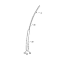
- FIG. 1 is an overall perspective view of glasses according to an embodiment of the present invention. It is a front view of glasses. It is a top view of spectacles. It is a bottom view of glasses. It is a right view of spectacles. It is a rear view of glasses. It is a perspective view of the front frame used for the spectacles of one Embodiment of this invention. It is a front view of a front frame. It is a left view of a front frame. It is a perspective view of the intermediate body used for the spectacles of one Embodiment of this invention. It is a top view of an intermediate body. It is a side view of an intermediate body. It is a front view of an intermediate body.
- connection member used for the spectacles of one Embodiment of this invention. It is a top view of a connection member. It is a side view of a connection member. It is a front view of a connection member. It is a perspective view of the temple used for the spectacles of one Embodiment of this invention. It is a left view of a temple. It is a front view of a temple. It is a top view of a temple. It is a side view which shows the connection state of an armor, an intermediate body, and a temple.
- FIG. 23 is a sectional view taken along line MM in FIG.
- FIG. 23 is a sectional view taken along line NN in FIG.
- FIG. 1 It is a figure which shows the aspect of the connection of the armor and intermediate body which concerns on a modification, and is a figure corresponding to FIG. It is a figure which shows the aspect of a connection with an intermediate body and a temple with the alloy which concerns on a modification. It is a figure which shows the measuring method of the spring property in the expansion operation
- the eyeglasses 1 of this embodiment are used for dustproof, for example.
- a front frame 10 As shown in FIGS. 1 to 6, a front frame 10, a pair of temples 3 provided on the left and right sides of the front frame 10, and a fluoroscope Left and right protective glasses 13.
- the end portion on the front frame 10 side is one end side or the front end side
- the end portion on the temple 3 side is the other end side or the rear end side (front-rear direction)
- the expansion and deployment directions of the temple 3 are The horizontal direction and the direction orthogonal to these directions are defined as the vertical direction.
- the front frame 10 includes left and right rims 11 and a bridge 15 that connects the upper portions of the left and right rims 11. Further, the front frame 10 has an armor 2 for attaching the temple 3. One end side (front end side) of the alloy 2 is connected to the rim 11, and the other end side (rear end side) is formed integrally with each of the left and right rims 11 so as to extend to the rear of the temple 3 (FIG. 1). To FIG. 6).
- the temple 3 is engaged with the temple or the ear, the temple main body 31 and the connecting portion 32 formed integrally with one end (front end) in the length direction of the temple main body 31. Is formed by.
- a connecting member 7 described later is inserted into the connecting portion 32.
- a second shaft hole 33 is formed in the connecting portion 32 for connection with the inserted connecting member 7.
- the temple 3 is attached to the armor 2 via an intermediate body 5 so as to be foldable.
- the solid line state in FIG. 3 shows the use state of the glasses 1 with the temple 3 deployed
- the chain line state shows the non-use state (storage state) of the glasses 1 with the temple 3 folded
- the temple 3 can be expanded and folded with respect to the armor 2 via the intermediate body 5 by rotating between the solid line state and the chain line state.
- Intermediate body 5 is connected to Yoroi 2 in a fixed state.
- the connection in the fixed state is that the intermediate body 5 is integrally connected at a fixed position so as not to move with respect to the armor 2.
- an insertion recess 22 having a “U” shape or a “V” shape is formed on the other end side of the armor 2 (FIG. 7). reference).
- a plate-like fixing piece 21 is formed at the insertion recess 22 (see FIG. 7). The thickness (size in the left-right direction) of the fixing piece 21 is thinner than other portions of the armor 2.
- the fixing piece 21 is inserted into the intermediate body 5 so as to be sandwiched between the intermediate bodies 5, and a part of the intermediate body 5 is inserted into the insertion recess 22, Accordingly, the intermediate body 5 is connected to the alloy 2 in a fixed state.
- a boss hole 23 passes through the fixing piece 21 in the thickness direction.
- the intermediate body 5 shown in FIG. 10 to FIG. 13 is integrally formed on a main body 51 (see FIG. 22 and the like) sandwiched between the armor 2 and the temple 3 and on one end side that is the side of the armor 2 with respect to the main body 51.
- the boss 55 is formed. Note that the sandwiching piece portion 52 and the sandwiching piece portion 53 are opposed to each other, but the protruding amount from the main body 51 is larger in the sandwiching piece portion 52 than in the sandwiching piece portion 53.
- One sandwiching piece 52 is inserted into the insertion recess 22 of the armor 2 as shown in FIGS.
- the pair of sandwiching pieces 52 and 53 sandwich the fixing piece 21 of the armor 2 from both the left and right sides.
- the boss 55 enters and engages with the boss hole 23 formed in the fixing piece 21 of the armor 2.
- the intermediate body 5 is connected to one end of the armor 2 in a fixed state.
- the sandwiching piece portion 52 is located outside the glasses 1 and the sandwiching piece portion 53 is located inside the glasses 1 in the left-right direction.
- the connection structure in which the boss 55 enters and engages with the boss hole 23 when a large external force is applied to the temple 3, the intermediate body 5, or the alloy 2, the intermediate body 5 is elastically deformed, and the intermediate body 5 and the alloy 2 are The connected state is released. That is, in FIG. 23, when the armor 2 is fixed and the temple 3 is largely rotated in the direction of the arrow A23 (when a rotational moment indicated by the arrow A23 is applied to the temple 3), the intermediate body 5 is elastically deformed. Thus, the intermediate body 5 comes off the armor 2.
- the intermediate body 5 can be assembled to the armor 2 relatively easily, and when a large external force is applied to the temple 3, the armor 2, the intermediate body 5, and the temple 3 are hardly damaged. .
- the arc-shaped concave portion 54 is formed so as to face the arc-shaped convex portion 34 formed on one end side of the temple 3, and the concave portion 54 and the convex portion 34 are opposed to each other in the vertical direction of the temple 3. Angle adjustment can be performed smoothly. That is, with the central axis of the second shaft portion 74 shown in FIG. 22 as the center of rotation, the temple 3 is, for example, about 1 ° to 10 ° in the direction of the arrow A22 with respect to the intermediate body 5 (the alloy 2). It is designed to rotate within an angular range.
- the main body 51 of the intermediate body 5 includes a main body piece 56 formed as a pair in the vertical direction, and a “U” -shaped connecting concave portion 57 formed between the main body pieces 56. have.
- the connection recess 57 is formed between the main body pieces 56 in the vertical direction by thinning one side surface of the main body portion 51 (the side surface located on the center side of the glasses 1 in the left-right direction).
- the main body piece 56 is a part sandwiched between the armor 2 and the temple 3.
- the connecting recess 57 is a part for connecting with the temple 3, and the connecting member 7 is inserted into the connecting recess 57 so that the intermediate body 5 and the temple 3 are connected to each other.
- first shaft holes 58 are formed on the opposing surfaces of the main body piece 56 on both sides of the connecting recess 57.
- the connecting member 7 shown in FIGS. 14 to 17 is formed in a Y shape when viewed from the side, and has a bifurcated connecting arm portion 71 on the intermediate body 5 side (one side) and a temple 3 side (the other side).
- the adjustment arm portion 72 is integrally formed.
- the connecting member 7 is arranged so as to span the intermediate body 5 and the temple 3, the connecting arm portion 71 is located on the intermediate body 5 side, and the adjustment arm portion 72 is located on the temple 3 side.
- the entire connecting member 7 is inserted into a flat plate-shaped hole (slit hole) 35 having a predetermined depth formed in the connecting portion 32 of the temple 3 and a connecting recess 57 of the intermediate body 5, so that It is designed to run over the body 5.
- the bifurcated connection arm 71 is inserted into the connection recess 57 of the intermediate body 5 as shown in FIGS.
- Each connecting arm portion 71 is formed with a first shaft portion 73 having a columnar shape, for example, which protrudes in the vertical direction perpendicular to the length direction (see FIGS. 22 and 16).
- the first shaft portion 73 is inserted into the first shaft hole 58 of the intermediate body 5, and the connecting member 7 (that is, the temple 3) is rotatably connected to the intermediate body 5 by this insertion.
- the central axis of the first shaft portion 73 extends substantially in the vertical direction, and the temple 3 becomes the center of rotation when the temple 3 is expanded and folded. That is, when the temple 3 is expanded or folded, the first shaft portion 73 rotates with respect to the first shaft hole 58, and the temple 3 rotates in the operation direction by this rotation.
- connection structure in which the first shaft portion 73 is inserted into the first shaft hole 58 and engaged, when a large external force is applied to the intermediate body 5, the connection member 7, or the like, the intermediate body 5 is elastically deformed, and the intermediate body The connection state between 5 and the connection member 7 (temple 3) is released.
- the connecting member 7 can be assembled to the intermediate body 5 relatively easily, and when a large external force is applied to the temple 3 or the like, the armor 2, the intermediate body 5, the temple 3 or the connecting member 7 It is hard to break.
- a columnar second shaft portion 74 protrudes in the left-right direction at a boundary portion between the connection arm portion 71 and the adjustment arm portion 72 in the connection member 7.
- the second shaft portion 74 is inserted into the second shaft hole 33 formed in the connecting portion 32 of the temple 3.
- the temple 3 can be turned up and down with respect to the intermediate body 5 (the armature 2) around the center axis of the second shaft portion 74, and the angle of the temple 3 in the up and down direction with respect to the armory 2 is changed. It is possible to do.
- the change in the vertical angle of the temple 3 can be adjusted by an angle adjustment mechanism (for example, a ratchet mechanism) 75 (see FIG. 22 and the like).
- the angle adjustment mechanism 75 is formed by the other end portion (claw portion) of the adjustment arm portion 72 and a gear portion (ratchet teeth) 76 (see FIG. 24) facing the other end portion of the adjustment arm portion 72.
- the gear portion 76 is formed along the vertical direction on the inner surface of the slit hole 35 of the temple 3, and the other end portion of the adjustment arm portion 72 is formed in a pointed shape that can be engaged with the gear portion 76.
- the temple 3 By rotating the temple 3 in the vertical direction around the second shaft portion 74 and changing the position of the base end portion of the adjustment arm portion 72 relative to the gear portion 76, the temple 3 stops at its vertical position.
- the angle of the temple 3 in the vertical direction can be adjusted. Since the vertical angle of the temple 3 can be adjusted in this way, the vertical position of the temple 3 with respect to the armor 2 (front frame 10) can be adjusted, so that the fit can be adjusted to suit the individual. , Improve wearability.
- the entire intermediate body 5 is formed of an elastic material that is more elastically deformed than the alloy 2, the temple 3, and the connecting member 7.
- the elastic material when the armor 2, the temple 3, and the connecting member 7 are formed of polycarbonate resin, polyamide resin, particularly nylon 66, can be used as the intermediate body 5, and the absorbed nylon 66 is preferably used. Can be used.
- the polycarbonate resin has a flexural modulus of about 2.30 to 2.50 GPa
- the absorbed nylon 66 has a flexural modulus of about 1.1 GPa. Is also easily elastically deformed. Nylon 66 does not easily lose moisture once it absorbs water. Further, the water absorption of nylon 66 is performed, for example, by adding a water absorption process of nylon 66 when the glasses 1 are manufactured.
- the intermediate body 5 is formed of nylon 66 that is more elastically deformed than the armature 2, the temple 3, and the connecting member 7 in this way, when the temple 3 is expanded, the temple 3 is subjected to the expansion operation.
- the intermediate body 5 is preferentially elastically deformed over the armor 2.
- the expansion operation of the temple 3 is performed by an excessive stress that causes deformation of the temple 3, the intermediate body 5 is preferentially further elastically deformed before the deformation of the temple 3.
- the intermediate body 5 is detached from either one or both of the alloy 2 and the temple 3.
- the connection between the armor 2 and the temple 3 is released, and excessive stress does not act, so that both the armor 2 (front frame 10) and the temple 3 are not damaged.
- the disengaged engagement portion (the boss 55 or the first shaft portion 73) can be re-engaged to return to the original state. It is possible.
- the intermediate body 5 is formed of nylon 66 that is easily elastically deformed
- the temple 3 is expanded with a stress within an allowable range that does not release the connection state described above
- the intermediate body 5 is elastically deformed in the expanding direction.
- the expansion angle of the temple 3 can be increased, the temple 3 can be expanded in accordance with the size of the face. Therefore, even if the wearer is different, the glasses 1 can be worn without a sense of incongruity.
- the front frame 10, the alloy 2, the temple 3, the intermediate body 5, and the connecting member 7 are formed of synthetic resin. That is, all the constituent members constituting the glasses 1 are made of synthetic resin, and no metal is used as the constituent members of the glasses 1. For this reason, it is not necessary to separate the glasses 1 when they are discarded, and the glasses 1 can be easily discarded and are easily regenerated.
- the intermediate body 5 may be made of an elastic material that is more easily elastically deformed than the armor 2, the temple 3, and the connecting member 7, and the armor 2, the temple 3, and the connecting member 7 are formed of a resin other than polycarbonate resin.
- a resin other than nylon 66 can be used as the intermediate body 5.
- the intermediate body 5 and the alloy 2 are connected by the boss 55 and the boss hole 23, and the intermediate body 5 and the connecting member 7 are connected by the first shaft portion 73 and the first shaft hole 58.
- the connecting portion is not limited to the illustrated structure as long as the connection is released by the elastic deformation of the intermediate body 5.
- the temple 3 may be directly connected to the intermediate body 5 by omitting the connecting member 7.
- a mark 89 is marked on the temple 3 with a pen at about 5 cm from the hinge (first shaft portion 75).
- the temple 3 is opened on the ruler 91 and the distance between the pair of marks 89 (the distance inside the pair of temples 3) is measured.
- One temple 3 is fixed to the ruler 91 and a hook of the push-pull gauge 93 is hooked on the other unfixed temple 3 to expand the pair of temples 3 (the distance between the pair of temples 3 increases). Pull slowly in the direction). If the hook of the push-pull gauge 93 slips, a measure such as winding a rubber band around the temple 3 is taken.
- the amount of expansion from the reference value (between the pair of marks 89)
- the value of the push-pull gauge 93 (the value of the pulling force by the push-pull gauge 93) is read every time 5 mm of the increase amount of the distance; the displacement of the distance between the temples 3 increases.
- test result of the expansion operation of the temple 3 of the glasses 1 will be described with reference to FIG.
- the test was performed with glasses of a kind other than the glasses 1 according to the embodiment of the present invention.
- FIG. 28 (a) is a table showing the test results in numerical values
- FIG. 28 (b) is a graph showing the test results.
- the “invention product” in FIG. 28 is the eyeglasses 1 according to the present embodiment, and the “glasses using a metal spring hinge” is the eyeglasses described in Japanese Patent Application Laid-Open No. 11-295663.
- “A” is the spectacles described in Japanese Patent Application Laid-Open No. 2011-186207
- “conventional product B” is ordinary protective spectacles in which a resin armor and a resin temple are connected by a metal hinge. It is.
- the load on the temple (the pulling force by the push-pull gauge 93) increased as the temple was opened (the distance between the pair of temple marks 89 was increased).
- the increase in load with respect to the displacement of the distance between the temples is more gradual than that of the conventional product (the other three types of glasses).
- the temple 3 can be expanded in accordance with the size of the face. Therefore, even if the width of the wearer's face is different, the glasses 1 can be worn without a sense of incongruity.
- the intermediate body 5 of the armor 2 when the intermediate body 5 of the armor 2 is installed, in the above description, a part of the armor 2 is sandwiched by a part of the intermediate body 5, but as shown in FIG. In addition, a part of the intermediate 5a may be sandwiched by a part of the armor 2a.
- a hole 81 having a predetermined depth is formed at the rear end of the armor 2a, a projecting piece 83 is provided in front of the intermediate body 5a, the projecting piece 83 is inserted into the hole 81, and the intermediate body 5a is partially inserted into the armor 2a. It is also possible to sandwich a part of
- another hole 85 is formed in the intermediate portion in the depth direction of the hole 81, and the intermediate portion in the protruding direction of the protruding piece 83 is formed. It is desirable to provide a cylindrical engagement piece 87 so that the engagement piece 87 enters the hole 85.
- the temple 3 is rotated with respect to the intermediate body 5 as shown in FIG. 3 around the axis extending in the vertical direction (the central axis of the first shaft portion 73).
- the temple 3 is slightly rotated with respect to the intermediate body 5 around the axis extending in the left-right direction (the central axis of the second shaft portion 74), as shown in FIG.
- the position of the rotation center axis of the temple 3b relative to the armor 2b may be changed as appropriate.
- the intermediate body 5b rotates about an axis (an axis extending substantially in the vertical direction) C1 with respect to the armor 2b, and the temple 3b is an axis (an axis extending in the substantially horizontal direction) with respect to the intermediate body 5b. ) It may be slightly rotated around C2.
Abstract
Description
2 ヨロイ
3 テンプル
5 中間体
7 連結部材
10 前枠
23 ボス孔
55 ボス
58 第1軸孔
73 第1軸部
Claims (4)
- 前枠のヨロイにテンプルが設けられた眼鏡において、
前記ヨロイ及び前記テンプルよりも弾性変形し易い弾性材料によって構成され、一端が前記ヨロイに連結され他端が前記テンプルに連結されて前記ヨロイと前記テンプルとの間に設けられた中間体を有することを特徴とする眼鏡。 - 請求項1に記載の眼鏡において、
前記中間体の一端が前記ヨロイに一体的に連結されており、前記中間体の他端が前記テンプルに連結されており、前記テンプルが折り畳み可能になっており、
前記中間体の弾性変形によって前記ヨロイ又は前記テンプルから離脱可能となっていることを特徴とする眼鏡。 - 請求項2に記載の眼鏡において、
前記中間体の他端と前記テンプルとの間に前記テンプルの折り畳み動作を支持する連結部材が設けられており、
前記連結部材と前記テンプルとの間に前記テンプルの上下方向の角度調整可能な角度調整機構が設けられていることを特徴とする眼鏡。 - 請求項1から請求項3のいずれか1項に記載の眼鏡において、
前記前枠、前記ヨロイ、前記テンプル、前記中間体が合成樹脂によって形成されていることを特徴とする眼鏡。
Priority Applications (4)
| Application Number | Priority Date | Filing Date | Title |
|---|---|---|---|
| JP2012554717A JP5690357B2 (ja) | 2011-01-27 | 2012-01-12 | 眼鏡 |
| CN2012800067566A CN103339551A (zh) | 2011-01-27 | 2012-01-12 | 眼镜 |
| EP12739489.8A EP2669731A4 (en) | 2011-01-27 | 2012-01-12 | GLASSES |
| US13/982,167 US20130308087A1 (en) | 2011-01-27 | 2012-01-12 | Glasses |
Applications Claiming Priority (2)
| Application Number | Priority Date | Filing Date | Title |
|---|---|---|---|
| JP2011-014670 | 2011-01-27 | ||
| JP2011014670 | 2011-01-27 |
Publications (1)
| Publication Number | Publication Date |
|---|---|
| WO2012102093A1 true WO2012102093A1 (ja) | 2012-08-02 |
Family
ID=46580666
Family Applications (1)
| Application Number | Title | Priority Date | Filing Date |
|---|---|---|---|
| PCT/JP2012/050519 WO2012102093A1 (ja) | 2011-01-27 | 2012-01-12 | 眼鏡 |
Country Status (6)
| Country | Link |
|---|---|
| US (1) | US20130308087A1 (ja) |
| EP (1) | EP2669731A4 (ja) |
| JP (1) | JP5690357B2 (ja) |
| CN (1) | CN103339551A (ja) |
| TW (1) | TWI500991B (ja) |
| WO (1) | WO2012102093A1 (ja) |
Cited By (1)
| Publication number | Priority date | Publication date | Assignee | Title |
|---|---|---|---|---|
| WO2014127394A1 (de) * | 2013-02-22 | 2014-08-28 | Silhouette International Schmied Ag | Scharniergelenk für eine brille |
Families Citing this family (9)
| Publication number | Priority date | Publication date | Assignee | Title |
|---|---|---|---|---|
| USD874555S1 (en) * | 2018-06-29 | 2020-02-04 | Revision Military Inc. | Eyewear temple bar |
| USD876531S1 (en) | 2018-06-29 | 2020-02-25 | Reyewear Acquisition, Inc. | Eyewear |
| USD866651S1 (en) * | 2018-07-12 | 2019-11-12 | Revision Military Inc. | Eyewear temple bar |
| USD874554S1 (en) | 2018-07-12 | 2020-02-04 | Reyewear Acquisition, Inc. | Eyewear |
| US10690937B1 (en) * | 2019-10-17 | 2020-06-23 | Banjohtos, LLC | Modular spectacles with multi-piece hinge |
| TWI727630B (zh) * | 2020-01-22 | 2021-05-11 | 富世達股份有限公司 | 智慧型眼鏡之折收支架結構 |
| USD1009979S1 (en) * | 2020-06-23 | 2024-01-02 | Eyenovation.DC LTD. | Bridge for glasses |
| USD1009141S1 (en) * | 2020-09-30 | 2023-12-26 | Oakley, Inc. | Eyeglasses |
| USD999273S1 (en) * | 2020-11-17 | 2023-09-19 | Chien-Mei Lin | Eyewear |
Citations (9)
| Publication number | Priority date | Publication date | Assignee | Title |
|---|---|---|---|---|
| JPH03135210A (ja) | 1989-10-06 | 1991-06-10 | Hewlett Packard Co <Hp> | 自動利得制御回路付きアンチログ回路 |
| JPH10282458A (ja) * | 1997-04-02 | 1998-10-23 | Nikon Corp | 眼 鏡 |
| JPH11295663A (ja) | 1998-04-07 | 1999-10-29 | Kawamoto Kogaku Kogyo Kk | 眼鏡用ヒンジ |
| JP2975361B1 (ja) | 1998-11-10 | 1999-11-10 | 株式会社タケダ企画 | 眼鏡用のバネ蝶番 |
| JP2003015090A (ja) * | 2001-07-02 | 2003-01-15 | Masunaga Optical Mfg Co Ltd | ヒンジレス眼鏡のテンプル過拡開防止機構 |
| JP3686292B2 (ja) | 1999-09-29 | 2005-08-24 | Hoya株式会社 | 眼鏡フレーム及び眼鏡 |
| JP2007101974A (ja) * | 2005-10-06 | 2007-04-19 | Isao Heii | 眼鏡の丁番構造 |
| JP2009086169A (ja) * | 2007-09-28 | 2009-04-23 | Aoyama Gankyo Kk | 眼鏡のテンプル連結構造及び眼鏡フレーム |
| JP2011186207A (ja) | 2010-03-09 | 2011-09-22 | Midori Anzen Co Ltd | 作業用眼鏡 |
Family Cites Families (14)
| Publication number | Priority date | Publication date | Assignee | Title |
|---|---|---|---|---|
| WO1995012139A1 (fr) * | 1993-10-29 | 1995-05-04 | O.G.K. Hanbai Co., Ltd. | Lunettes de soleil |
| US5555038A (en) * | 1994-10-28 | 1996-09-10 | Bausch & Lomb Incorporated | Unitary lens for eyewear |
| CA2181020A1 (en) * | 1996-07-11 | 1998-01-12 | Martin Pernicka | Eyeglass construction |
| US5980038A (en) * | 1999-01-21 | 1999-11-09 | Crews, Inc. | Angularly adjustable temples for eyeglasses |
| CN2554653Y (zh) * | 2002-04-17 | 2003-06-04 | 广州大新光学有限公司 | 一种可作眼镜角度调节的新型眼镜脚组件 |
| CN2622728Y (zh) * | 2003-05-22 | 2004-06-30 | 广州大新光学有限公司 | 眼镜角度调整结构 |
| US20060221299A1 (en) * | 2005-04-01 | 2006-10-05 | Ta-Tung Wang-Lee | Angle adjustment mechanism for eyeglass temples |
| TWM281188U (en) * | 2005-08-04 | 2005-11-21 | Doris Ind Co Ltd | Improved structure for arm of optical glasses |
| US7033021B1 (en) * | 2005-11-14 | 2006-04-25 | Wen-Hsuing Wu | Device for connecting eyeglass frame and temple or headband |
| US20090027615A1 (en) * | 2007-07-24 | 2009-01-29 | Lin Yun Chen | Connecting structure for glass frame and wearing portion |
| JP4877632B2 (ja) * | 2007-11-06 | 2012-02-15 | 山本光学株式会社 | 眼鏡 |
| TWI360676B (en) * | 2008-06-26 | 2012-03-21 | High Rainbow Ent Co Ltd | Eyeglasses |
| JP5071907B2 (ja) * | 2008-08-27 | 2012-11-14 | 山本光学株式会社 | 眼鏡 |
| CN201662660U (zh) * | 2010-04-16 | 2010-12-01 | 王信胜 | 眼镜脚的角度调整结构 |
-
2012
- 2012-01-12 CN CN2012800067566A patent/CN103339551A/zh active Pending
- 2012-01-12 US US13/982,167 patent/US20130308087A1/en not_active Abandoned
- 2012-01-12 WO PCT/JP2012/050519 patent/WO2012102093A1/ja active Application Filing
- 2012-01-12 EP EP12739489.8A patent/EP2669731A4/en not_active Withdrawn
- 2012-01-12 JP JP2012554717A patent/JP5690357B2/ja active Active
- 2012-01-18 TW TW101101895A patent/TWI500991B/zh active
Patent Citations (9)
| Publication number | Priority date | Publication date | Assignee | Title |
|---|---|---|---|---|
| JPH03135210A (ja) | 1989-10-06 | 1991-06-10 | Hewlett Packard Co <Hp> | 自動利得制御回路付きアンチログ回路 |
| JPH10282458A (ja) * | 1997-04-02 | 1998-10-23 | Nikon Corp | 眼 鏡 |
| JPH11295663A (ja) | 1998-04-07 | 1999-10-29 | Kawamoto Kogaku Kogyo Kk | 眼鏡用ヒンジ |
| JP2975361B1 (ja) | 1998-11-10 | 1999-11-10 | 株式会社タケダ企画 | 眼鏡用のバネ蝶番 |
| JP3686292B2 (ja) | 1999-09-29 | 2005-08-24 | Hoya株式会社 | 眼鏡フレーム及び眼鏡 |
| JP2003015090A (ja) * | 2001-07-02 | 2003-01-15 | Masunaga Optical Mfg Co Ltd | ヒンジレス眼鏡のテンプル過拡開防止機構 |
| JP2007101974A (ja) * | 2005-10-06 | 2007-04-19 | Isao Heii | 眼鏡の丁番構造 |
| JP2009086169A (ja) * | 2007-09-28 | 2009-04-23 | Aoyama Gankyo Kk | 眼鏡のテンプル連結構造及び眼鏡フレーム |
| JP2011186207A (ja) | 2010-03-09 | 2011-09-22 | Midori Anzen Co Ltd | 作業用眼鏡 |
Non-Patent Citations (1)
| Title |
|---|
| See also references of EP2669731A4 * |
Cited By (2)
| Publication number | Priority date | Publication date | Assignee | Title |
|---|---|---|---|---|
| WO2014127394A1 (de) * | 2013-02-22 | 2014-08-28 | Silhouette International Schmied Ag | Scharniergelenk für eine brille |
| US9519157B2 (en) | 2013-02-22 | 2016-12-13 | Silhouette International Schmied Ag | Hinge joint for eyeglasses |
Also Published As
| Publication number | Publication date |
|---|---|
| CN103339551A (zh) | 2013-10-02 |
| TW201239448A (en) | 2012-10-01 |
| EP2669731A4 (en) | 2014-06-25 |
| JP5690357B2 (ja) | 2015-03-25 |
| TWI500991B (zh) | 2015-09-21 |
| EP2669731A1 (en) | 2013-12-04 |
| JPWO2012102093A1 (ja) | 2014-06-30 |
| US20130308087A1 (en) | 2013-11-21 |
Similar Documents
| Publication | Publication Date | Title |
|---|---|---|
| JP5690357B2 (ja) | 眼鏡 | |
| TWI587015B (zh) | 具有撓曲構件之眼鏡 | |
| EP2069853B1 (en) | Spectacles frame having a composite hinge | |
| US7422323B2 (en) | Hinge system for eyewear | |
| US7621633B1 (en) | Reversible eyewear and associated method | |
| US20050052612A1 (en) | Universal eyeglass attachment | |
| US9454017B2 (en) | Glasses | |
| JP2002014303A5 (ja) | ||
| JP2012519307A (ja) | テレスコピックヒンジを備えた眼鏡フレーム及び当該フレームのヒンジ | |
| CA2893146C (en) | Eyewear with locking lens frame | |
| EP2107415B1 (en) | Eyeglass frame | |
| JP6189872B2 (ja) | 弓状曲げ部材を有するアイウェア | |
| US9052532B2 (en) | Eyeglass frame | |
| JP2003121800A (ja) | メガネフレームのツル | |
| KR200455234Y1 (ko) | 플라스틱 안경테용 탄성힌지 | |
| JP5190533B2 (ja) | 眼鏡フレーム | |
| KR101246743B1 (ko) | 안경다리 연결장치 및 이를 이용한 안경 | |
| JPH10282458A (ja) | 眼 鏡 | |
| TWI504966B (zh) | 眼鏡框 | |
| JP2006293158A (ja) | 眼鏡 | |
| JP2011090269A (ja) | 眼鏡のばねヒンジ機構 | |
| JP2013061396A (ja) | 眼鏡フレーム | |
| JP2003121798A (ja) | メガネフレーム | |
| JP2005181921A (ja) | 眼鏡用防塵具 | |
| TWM325513U (en) | Glasses structure |
Legal Events
| Date | Code | Title | Description |
|---|---|---|---|
| 121 | Ep: the epo has been informed by wipo that ep was designated in this application |
Ref document number: 12739489 Country of ref document: EP Kind code of ref document: A1 |
|
| DPE1 | Request for preliminary examination filed after expiration of 19th month from priority date (pct application filed from 20040101) | ||
| ENP | Entry into the national phase |
Ref document number: 2012554717 Country of ref document: JP Kind code of ref document: A |
|
| WWE | Wipo information: entry into national phase |
Ref document number: 13982167 Country of ref document: US |
|
| WWE | Wipo information: entry into national phase |
Ref document number: 1301004164 Country of ref document: TH |
|
| NENP | Non-entry into the national phase |
Ref country code: DE |
|
| WWE | Wipo information: entry into national phase |
Ref document number: 2012739489 Country of ref document: EP |