WO2012102026A1 - 入力装置 - Google Patents
入力装置 Download PDFInfo
- Publication number
- WO2012102026A1 WO2012102026A1 PCT/JP2012/000436 JP2012000436W WO2012102026A1 WO 2012102026 A1 WO2012102026 A1 WO 2012102026A1 JP 2012000436 W JP2012000436 W JP 2012000436W WO 2012102026 A1 WO2012102026 A1 WO 2012102026A1
- Authority
- WO
- WIPO (PCT)
- Prior art keywords
- piezoelectric element
- input device
- operation position
- tactile sensation
- ultrasonic wave
- Prior art date
Links
Images


Classifications
-
- G—PHYSICS
- G06—COMPUTING; CALCULATING OR COUNTING
- G06F—ELECTRIC DIGITAL DATA PROCESSING
- G06F3/00—Input arrangements for transferring data to be processed into a form capable of being handled by the computer; Output arrangements for transferring data from processing unit to output unit, e.g. interface arrangements
- G06F3/01—Input arrangements or combined input and output arrangements for interaction between user and computer
- G06F3/03—Arrangements for converting the position or the displacement of a member into a coded form
- G06F3/041—Digitisers, e.g. for touch screens or touch pads, characterised by the transducing means
- G06F3/043—Digitisers, e.g. for touch screens or touch pads, characterised by the transducing means using propagating acoustic waves
-
- G—PHYSICS
- G06—COMPUTING; CALCULATING OR COUNTING
- G06F—ELECTRIC DIGITAL DATA PROCESSING
- G06F2203/00—Indexing scheme relating to G06F3/00 - G06F3/048
- G06F2203/041—Indexing scheme relating to G06F3/041 - G06F3/045
- G06F2203/04101—2.5D-digitiser, i.e. digitiser detecting the X/Y position of the input means, finger or stylus, also when it does not touch, but is proximate to the digitiser's interaction surface and also measures the distance of the input means within a short range in the Z direction, possibly with a separate measurement setup
Definitions
- the present invention relates to an input device.
- Patent Document 2 describes a technique for applying various tactile sensations to skin (for example, a fingertip) using ultrasonic waves.
- a finger, a stylus or the like is in direct contact with the screen, so the screen may be stained with oil or the like, or marks of the stylus may be left on the screen.
- An object of the present invention is to provide an input device capable of noncontactly detecting an operation corresponding to an operation position display displayed on a screen.
- the present invention provides a display unit that displays a plurality of operation positions; A detection unit for non-contactingly detecting an operation on an operation position set in a specific space in front of the input device corresponding to each of the plurality of operation position indications; Have The detection unit is A first piezoelectric element for emitting ultrasonic waves toward a space in front of the input device; A second piezoelectric element that detects the ultrasonic wave oscillated by the first piezoelectric element; A determination unit that determines which operation position has been operated based on the detection result of the second piezoelectric element; Providing an input device characterized by comprising:
- the operation performed on the operation position corresponding to the operation position display displayed on the display unit can be detected in a noncontact manner.
- FIG. 1 is a front view showing a portable terminal device 100 as an input device according to the first embodiment
- FIG. 2 is a block diagram of the portable terminal device 100
- FIG. FIG. 1 is a front view showing a portable terminal device 100 as an input device according to the first embodiment
- FIG. 2 is a block diagram of the portable terminal device 100
- FIG. FIG. 1 is a front view showing a portable terminal device 100 as an input device according to the first embodiment
- FIG. 2 is a block diagram of the portable terminal device 100
- FIG. FIG. 1 is a front view showing a portable terminal device 100 as an input device according to the first embodiment
- FIG. 2 is a block diagram of the portable terminal device 100
- FIG. FIG. 1 is a front view showing a portable terminal device 100 as an input device according to the first embodiment
- FIG. 2 is a block diagram of the portable terminal device 100
- FIG. FIG. 1 is a front view showing a portable terminal device 100 as an input device according to the first embodiment
- FIG. 2 is a block diagram
- the mobile terminal device 100 includes a display unit 60 that performs a plurality of operation position displays (for example, operation position displays 61 to 66), and a front surface of the mobile terminal device 100 corresponding to each of the plurality of operation position displays.
- a display unit 60 that performs a plurality of operation position displays (for example, operation position displays 61 to 66), and a front surface of the mobile terminal device 100 corresponding to each of the plurality of operation position displays.
- a first piezoelectric element (oscillating piezoelectric element 31) that oscillates an ultrasonic wave toward a space in front of 100 (for example, a space in the front of the display unit 60) and an ultrasonic wave oscillated by the first piezoelectric element are detected It has a second piezoelectric element (receiving piezoelectric element 21) and a determination unit 42 which determines which operation position has been performed based on the detection result of the second piezoelectric element.
- the mobile terminal device 100 is, for example, a mobile phone, a PDA (Personal Digital Assistant), a small game device, a laptop personal computer, or the like. The details will be described below.
- the mobile terminal device 100 includes a housing 101 and a display unit 60 provided in the housing 101.
- FIG. 1 shows an example in which the portable terminal device 100 is a tablet type
- the portable terminal device 100 may have other forms. That is, the portable terminal device 100 may be a foldable type having the first and second housings foldably connected to each other, or the first and second housings slidably connected to each other. It may be a slide type having a body.
- the display unit 60 is configured of, for example, a liquid crystal display device or the like.
- the display unit 60 displays various types of information on the display screen 60a. These displays include displays of a plurality of operation position displays (for example, operation position displays 61 to 66).
- the display screen 60a is formed, for example, in a rectangular shape.
- the portable terminal device 100 includes an oscillating piezoelectric element 31 for oscillating an ultrasonic wave toward a space in front of the portable terminal 100 and a receiving piezoelectric element 21 for detecting an ultrasonic wave oscillated from the oscillating piezoelectric element 31 (21a , 21b, 21c, and 21d), and a tactile sensation giving piezoelectric element (third piezoelectric element) 81 that oscillates an ultrasonic wave toward the operation position.
- the oscillation piezoelectric element 31, the reception piezoelectric element 21, and the tactile sensation application piezoelectric element 81 are provided at positions near the display unit 60 in the housing 101.
- the portable terminal device 100 has a plurality of at least one of the oscillation piezoelectric element 31 and the reception piezoelectric element 21.
- the mobile terminal device 100 includes, for example, a plurality of receiving piezoelectric elements 21.
- the receiving piezoelectric elements 21 are disposed, for example, at positions corresponding to the four sides of the display screen 60a.
- the mobile terminal device 100 also has, for example, a plurality of tactile sensation providing piezoelectric elements 81.
- the portable terminal device 100 includes a control unit 40 in addition to the oscillation piezoelectric element 31, the reception piezoelectric element 21, the tactile sensation imparting piezoelectric element 81 and the display unit 60.
- the control unit 40 controls the operation of the oscillation control unit 41 that controls the operation of the oscillation piezoelectric element 31, the determination unit 42, the display control unit 43 that controls the operation of the display unit 60, and the tactile sensation application piezoelectric element 81. And a tactile sensation application control unit 44.
- an ultrasonic wave can be oscillated from the oscillation piezoelectric element 31.
- the ultrasonic wave oscillated by the oscillating piezoelectric element 31 is detected by each receiving piezoelectric element 21.
- Each receiving piezoelectric element 21 detects the ultrasonic wave of the frequency oscillated by the oscillating piezoelectric element 31. It is preferable that the resonant frequency of the receiving piezoelectric element 21 match the transmission frequency of the oscillating piezoelectric element 31.
- the detection results of the reception piezoelectric elements 21 are input to the determination unit 42, respectively.
- the determination unit 42 determines which operation position has been operated based on the detection results of the reception piezoelectric elements 21.
- the tactile sensation application control unit 44 controls the tactile sensation application piezoelectric elements 81 to oscillate ultrasonic waves from the tactile sensation application piezoelectric elements 81 toward the operation position, thereby performing an operation (for example, a finger 1 (see FIG. 3). Or a stylus (not shown) or the like).
- the operation position is at a position away from the display screen 60a.
- the operation positions are set, for example, in the spaces in front of the operation position displays 61 to 66, respectively.
- FIG. 3 shows, as an example, a state in which the operating position 51 corresponding to the operating position display 62 is operated by the finger 1.
- the ultrasonic waves output from the oscillating piezoelectric element 31 are reflected by the finger 1 and then detected by the receiving piezoelectric elements 21, but are reflected toward the receiving piezoelectric elements 21 according to the position of the finger 1.
- the determination part 42 is storing beforehand the detection value by each piezoelectric element 21 for reception as a table for every operation position. Then, the determination unit 42 extracts the operation position corresponding to the detection value of each reception piezoelectric element 21 from the table, and determines that the operation to the operation position is performed.
- the determination unit 42 may determine to which operation position the operation has been performed by calculation using detection values of the reception piezoelectric elements 21.
- the vertical position of the operation position is determined from the ratio between the detection value of the reception piezoelectric element 21a located on the display screen 60a and the detection value of the reception piezoelectric element 21b located below the display screen 60a. Determining the lateral position of the operation position from the ratio of the detection value by the reception piezoelectric element 21c positioned on the left of the display screen 60a to the detection value by the reception piezoelectric element 21d positioned on the right of the display screen 60a
- the operation position may be specified.
- each operation position be located in the same plane, thereby facilitating the operation by the user.
- the distance from the display screen 60a to each operation position is preferably 5 cm or less (more preferably 3 cm or less), whereby the operation can be detected with higher accuracy.
- the tactile sensation application control unit 44 controls the tactile sensation application piezoelectric element 81 to make the finger 1 apply ultrasonic waves. , Give the finger 1 a tactile sensation.
- the value of the phase of the ultrasonic wave oscillated from each tactile sensation applying piezoelectric element 81 (or the value of the relative displacement amount of the phase of the ultrasonic wave oscillated from each tactile sensation applying piezoelectric element 81) is controlled.
- the position at which the finger 1 or the like is given a tactile sensation can be adjusted. Therefore, in the present embodiment, the value of the phase of the ultrasonic wave oscillated from each tactile sense imparting piezoelectric element 81 and the relative displacement amount thereof are controlled so that the tactile sensation can be given at the operation position where the operation is detected.
- a plurality of types of tactile sensations for example, hard tactile sensation and soft tactile sensation
- Texture slippery texture, unevenness texture, etc.
- the control unit 40 executes other processing according to the operation. For example, as shown in FIG. 1, in the operation position displays 61 to 66, an operation position display 61 indicating an operation position (not shown) instructing the activation of the application and an operation indicating the operation position 51 instructing an activation of the address book Position display 62, operation position display 63 indicating an operation position (not shown) instructing an activation of an electronic mail function, operation position display 64 indicating an operation position (not shown) instructing an activation of a camera function, activation of a calculator function An operation position display 65 indicating an operation position (not shown) to be instructed and an operation position display 66 indicating an operation position (not shown) instructing activation of various setting functions are included, and the control unit 40 has these functions. Execute processing according to
- FIG. 4 is a schematic view of the oscillation piezoelectric element 31. As shown in FIG.
- the oscillating piezoelectric element 31 includes, for example, a sheet-like vibrating member 32, a vibrator 33, and a support member 34.
- the vibrator 33 is, for example, a piezoelectric vibrator, and is attached to one surface of the vibrating member 32.
- the support member 34 supports the edge of the vibrating member 32.
- the support member 34 is fixed to, for example, a circuit board (not shown) or the housing 101 of the mobile terminal device 100.
- the oscillation control unit 41 constitutes an oscillation circuit that vibrates the vibrator 33 by inputting the oscillation signal to the vibrator 33 and causes the vibrator 33 and the vibrating member 32 to oscillate a sound wave.
- the vibrating member 32 vibrates by the vibration generated from the vibrator 33, and oscillates a sound wave having a frequency of, for example, 20 kHz or more.
- the vibrator 33 also oscillates, for example, a sound wave having a frequency of 20 kHz or more when the vibrator 33 vibrates.
- the vibrating member 32 also adjusts the fundamental resonant frequency of the vibrator 33.
- the fundamental resonant frequency of the mechanical oscillator depends on the load weight and the compliance. Since the compliance is mechanical rigidity of the vibrator, controlling the rigidity of the vibrating member 32 can control the fundamental resonance frequency of the vibrator 33.
- the thickness of the vibrating member 32 is preferably 5 ⁇ m or more and 500 ⁇ m or less.
- index which shows rigidity is 1 Gpa or more and 500 GPa or less. If the rigidity of the vibrating member 32 is too low or too high, there is a possibility that the characteristics and reliability of the mechanical vibrator will be impaired.
- the material constituting the vibrating member 32 is not particularly limited as long as it is a material having a high elastic modulus with respect to the vibrator 33 which is a brittle material such as metal or resin, but from the viewpoint of processability and cost Stainless steel is preferable.
- the planar shape of the vibrator 33 is circular.
- the planar shape of the vibrator 33 is not limited to a circle.
- the vibrator 33 is fixed to the vibrating member 32 by an adhesive on the entire surface of the vibrator 33 facing the vibrating member 32. Thus, the entire surface on one side of the vibrator 33 is restrained by the vibrating member 32.
- the oscillation control unit 41 generates an electrical signal to be input to the vibrator 33, that is, a modulation signal in the oscillation piezoelectric element 31.
- the transport wave of the modulation signal is, for example, an ultrasonic wave having a frequency of 20 kHz or more, and specifically, for example, an ultrasonic wave of 100 kHz.
- the oscillation control unit 41 controls the oscillation piezoelectric element 31 so as to obtain a predetermined oscillation output.
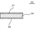
- FIG. 5 is a cross-sectional view showing a layered structure of the vibrator 33 in the thickness direction.
- the vibrator 33 has a piezoelectric body 36, an upper surface electrode 37 and a lower surface electrode 38.
- the piezoelectric body 36 is polarized in the thickness direction.
- the material constituting the piezoelectric body 36 may be either an inorganic material or an organic material as long as it has a piezoelectric effect. However, a material having high electromechanical conversion efficiency, for example, zirconate titanate (PZT) or barium titanate (BaTiO 3 ) is preferable.
- the thickness h1 of the piezoelectric body 36 is, for example, 10 ⁇ m or more and 1 mm or less. If the thickness h1 is less than 10 ⁇ m, there is a possibility that the vibrator 33 may be damaged when the oscillating piezoelectric element 31 is manufactured.
- the thickness h1 is more than 1 mm, the electromechanical conversion efficiency is too low, and there is a possibility that a sufficient magnitude of vibration can not be obtained.
- the reason is that, when the thickness of the vibrator 33 is increased, the electric field strength in the piezoelectric vibrator decreases in inverse proportion.
- the material which comprises the upper surface electrode 37 and the lower surface electrode 38 is not specifically limited, For example, silver and silver / palladium can be used. Silver is used as a low-resistance, general-purpose electrode material, and thus has advantages in manufacturing process and cost. Since silver / palladium is a low resistance material excellent in oxidation resistance, it is advantageous from the viewpoint of reliability.
- the thickness h2 of the upper surface electrode 37 and the lower surface electrode 38 is not particularly limited, but it is preferable that the thickness h2 is 1 ⁇ m or more and 50 ⁇ m or less. If the thickness h2 is less than 1 ⁇ m, it is difficult to form the upper surface electrode 37 and the lower surface electrode 38 uniformly, and as a result, the electromechanical conversion efficiency may be reduced. When the film thickness of the upper surface electrode 37 and the lower surface electrode 38 exceeds 100 ⁇ m, there is a possibility that the upper surface electrode 37 and the lower surface electrode 38 become a constraining surface with respect to the piezoelectric body 36 to lower energy conversion efficiency.
- the vibrator 33 can have an outer diameter of ⁇ 18 mm, an inner diameter of ⁇ 12 mm, and a thickness of 100 ⁇ m. Further, as the upper surface electrode 37 and the lower surface electrode 38, for example, a silver / palladium alloy (weight ratio is, for example, 7: 3) having a thickness of 8 ⁇ m can be used. Further, as the vibrating member 32, phosphor bronze having an outer diameter of ⁇ 20 mm and a thickness of 50 ⁇ m (0.3 mm) can be used.
- the support member 34 functions as a case of the oscillation piezoelectric element 31, and is formed in, for example, a cylindrical (for example, cylindrical) shape with an outer diameter of ⁇ 22 mm and an inner diameter of ⁇ 20 mm.
- FIG. 4 is a schematic view of the receiving piezoelectric element 21. As shown in FIG. 4
- the receiving piezoelectric element 21 is configured in the same manner as the oscillating piezoelectric element 31.
- the vibrators 33 of the receiving piezoelectric elements 21 individually generate electric signals according to the received ultrasonic waves, and output the electric signals to the determination unit 42 (as a detection result of the ultrasonic waves).
- the determination unit 42 determines which operation position has been operated based on the electric signal input from each of the reception piezoelectric elements 21.
- the oscillation piezoelectric element 31 has a function as a speaker for outputting an ultrasonic wave, whereas the reception piezoelectric element 21 functions as a microphone for detecting an ultrasonic wave.
- the piezoelectric element 81 for tactile sense provision and the tactile sense provision control part 44 are also comprised similarly to the piezoelectric element 31 for oscillation, and the oscillation control part 41.
- FIG. 1 the piezoelectric element 81 for tactile sense provision and the tactile sense provision control part 44 are also comprised similarly to the piezoelectric element 31 for oscillation, and the oscillation control part 41.
- the detection unit detects the operation performed on the operation position corresponding to each operation position display by the oscillation control unit 41, the oscillation piezoelectric element 31, the reception piezoelectric element 21 and the determination unit 42 in a noncontact manner. Is configured.
- FIG. 7 is a flowchart showing the flow of the operation of the first embodiment.
- the mobile terminal device 100 repeatedly performs the process of FIG. 7 at predetermined time intervals.
- the user performs an operation on any one of the operation positions (the operation position 51 and the like) indicated by the plurality of operation position displays 61 to 66. That is, the finger 1 is moved to a desired operation position. Then, the detection unit detects the operation (Y in step S11).
- the tactile sensation application control unit 44 performs processing for applying a tactile sensation to the finger 1 (step S12).
- step S13 is performed in parallel with step S12 (or following step S12).
- step S13 other processing (processing except for the processing in step S12) corresponding to the operation is performed. Specifically, for example, processing for activating an application, an address book, an electronic mail function, a camera function, a calculator function, various setting functions, and the like is performed.
- the operation performed on the operation position (the operation position 51 or the like) indicated by the operation position display 61 to 66 displayed on the display unit 60 is detected without contact. can do. Therefore, unlike a touch panel in which a finger, a stylus or the like is brought into direct contact with the screen, it is possible to suppress the screen from being stained with oil or the like, and the trace of the stylus remaining on the screen.
- the operation with respect to the operation positions disposed at a plurality of locations in two dimensions It can be easily detected. More specifically, at least one of the oscillation piezoelectric element 31 and the reception piezoelectric element 21 (for example, the reception piezoelectric element 21) is disposed at a position corresponding to each of the four sides of the display unit 60. By this, it is possible to easily detect the operation with respect to the operation positions which are two-dimensionally arranged at a plurality of places.
- the tactile sensation application piezoelectric element 81 for oscillating ultrasonic waves toward the operation position and the tactile sensation application piezoelectric element 81 the tactile sensation is given to the object (such as the finger 1) operated by the ultrasonic wave.
- a tactile sensation application control unit 44 that performs control Therefore, even when detecting the operation on the display screen 60a in a non-contact manner, it is possible to give the user a touch as if it were touched, and the user can easily recognize that the operation has been performed. .
- the position at which the tactile sensation is provided can be easily adjusted, so that the tactile sensation can be provided at the operation position.
- FIG. 8 is a block diagram of a portable terminal device 100 as an input device according to the second embodiment.
- the tactile sensation is provided using the tactile sensation application piezoelectric element 81
- the second embodiment of the oscillation piezoelectric device 31 and the reception piezoelectric device 21.
- a tactile sensation is provided using at least one piezoelectric element (for example, the receiving piezoelectric element 21). More specifically, by offsetting the timing of detecting an operation using the receiving piezoelectric element 21 and the timing of applying a tactile sense using the receiving piezoelectric element 21 (by time division), the receiving piezoelectric The element 21 can be used both for operation detection and for tactile sensation.
- each reception piezoelectric element 21 oscillates an ultrasonic wave under the control of the tactile sensation application control unit 44, and the ultrasonic wave imparts a tactile sensation to the finger 1 and the like.
- the oscillation piezoelectric element 31 and the reception piezoelectric element 21 a tactile sensation is given to the object (for example, the finger 1) which has been operated by ultrasonic waves. Therefore, the enlargement of the portable terminal device 100 can be suppressed by using the piezoelectric element for detection and the piezoelectric element for providing tactile sensation.
- FIG. 9 is a front view showing a portable terminal device 100 as an input device according to the third embodiment.
- the example in which the receiving piezoelectric element 21 is disposed along each of the four sides of the display unit 60 has been described.
- the third embodiment as shown in FIG. 9, a plurality of receiving piezoelectric elements 21 are arranged along the two sides of the display unit 60, respectively. According to such a third embodiment, the same effect as that of the first embodiment or the second embodiment can be obtained.
- the input device is a portable terminal device.
- the input device may be a stationary device such as an ATM (Automated Teller Machine).
- a plurality of oscillating piezoelectric elements 31 may be provided in the input device.
- the tactile sensation application control unit 44 causes the tactile sensation application piezoelectric element 81 (or the oscillation so that the tactile sensation becomes stronger as the position of the operated object is closer to the surface including the display unit 60 (display screen 60a).
- the piezoelectric element 31 for reception or the piezoelectric element for reception 21) may be controlled.
- the determination unit 42 determines the distance between the object on which the operation is performed and the plane including the display unit 60 (display screen 60a) based on the detection result of the reception piezoelectric element 21. Then, the tactile sensation application control unit 44 controls the tactile sensation application piezoelectric element 81 (or the oscillation piezoelectric element 31 or the reception piezoelectric element 21) such that the closer the determined distance is, the stronger the tactile sensation.
Landscapes
- Engineering & Computer Science (AREA)
- General Engineering & Computer Science (AREA)
- Theoretical Computer Science (AREA)
- Physics & Mathematics (AREA)
- Human Computer Interaction (AREA)
- General Physics & Mathematics (AREA)
- Acoustics & Sound (AREA)
- Position Input By Displaying (AREA)
- User Interface Of Digital Computer (AREA)
Abstract
入力装置(例えば、携帯端末装置(100))は、複数の操作位置表示(例えば操作位置表示(61~66))を行う表示部(60)と、これら複数の操作位置表示の各々に対応して入力装置の正面の特定の空間に設定された操作位置に対する操作を非接触式で検出する検出部と、を有する。検出部は、入力装置の正面の空間に向けて超音波を発振する第1圧電素子(発振用圧電素子(31))と、第1圧電素子より発振された超音波を検出する第2圧電素子(受信用圧電素子(21))と、第2圧電素子による検出結果に基づいて、何れの操作位置に対する操作が行われたかを判定する判定部を有する。
Description
本発明は、入力装置に関する。
表示画面を操作部として兼用させるタッチパネルに関する技術は、例えば、特許文献1に記載されている。特許文献1の技術では、圧電素子を用いて、画面に対する指の接触を検出する。
なお、特許文献2には、超音波を用いて皮膚(例えば指先)に多様な触感を付与する技術が記載されている。
タッチパネルでは、指やスタイラス等が画面に直接接触するため、画面が手の脂などで汚れたり、画面にスタイラスの跡が残ったりする。
本発明の目的は、画面に表示された操作位置表示に対応する操作を、非接触式で検出することが可能な入力装置を提供することにある。
本発明は、複数の操作位置表示を行う表示部と、
前記複数の操作位置表示の各々に対応して入力装置の正面の特定の空間に設定された操作位置に対する操作を非接触式で検出する検出部と、
を有し、
前記検出部は、
前記入力装置の正面の空間に向けて超音波を発振する第1圧電素子と、
前記第1圧電素子より発振された前記超音波を検出する第2圧電素子と、
前記第2圧電素子による検出結果に基づいて、何れの前記操作位置に対する操作が行われたかを判定する判定部と、
を有することを特徴とする入力装置を提供する。
前記複数の操作位置表示の各々に対応して入力装置の正面の特定の空間に設定された操作位置に対する操作を非接触式で検出する検出部と、
を有し、
前記検出部は、
前記入力装置の正面の空間に向けて超音波を発振する第1圧電素子と、
前記第1圧電素子より発振された前記超音波を検出する第2圧電素子と、
前記第2圧電素子による検出結果に基づいて、何れの前記操作位置に対する操作が行われたかを判定する判定部と、
を有することを特徴とする入力装置を提供する。
本発明によれば、表示部に表示された操作位置表示と対応する操作位置に対して行われた操作を非接触式で検出することができる。
上述した目的、およびその他の目的、特徴および利点は、以下に述べる好適な実施の形態、およびそれに付随する以下の図面によってさらに明らかになる。
以下、本発明の実施形態について、図面を用いて説明する。なお、すべての図面において、同様の構成要素には同一の符号を付し、適宜に説明を省略する。
〔第1の実施形態〕
図1は第1の実施形態に係る入力装置としての携帯端末装置100を示す正面図、図2は携帯端末装置100のブロック図、図3は操作位置51に対して指1で操作を行う状態を示す側面図である。
図1は第1の実施形態に係る入力装置としての携帯端末装置100を示す正面図、図2は携帯端末装置100のブロック図、図3は操作位置51に対して指1で操作を行う状態を示す側面図である。
本実施形態に係る携帯端末装置100は、複数の操作位置表示(例えば操作位置表示61~66)を行う表示部60と、これら複数の操作位置表示の各々に対応して携帯端末装置100の正面の(例えば、表示部60の正面の)特定の空間に設定された操作位置(操作位置51等)に対する操作を非接触式で検出する検出部と、を有し、検出部は、携帯端末装置100の正面の空間(例えば、表示部60の正面の空間)に向けて超音波を発振する第1圧電素子(発振用圧電素子31)と、第1圧電素子より発振された超音波を検出する第2圧電素子(受信用圧電素子21)と、第2圧電素子による検出結果に基づいて、何れの操作位置に対する操作が行われたかを判定する判定部42と、を有する。なお、携帯端末装置100は、例えば、携帯電話機、PDA(Personal Digital Assistant)、小型ゲーム機器、ラップトップ型パーソナルコンピュータなどである。以下、詳細に説明する。
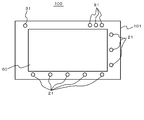
図1に示すように、携帯端末装置100は、筐体101と、この筐体101に設けられた表示部60と、を有している。なお、図1では、携帯端末装置100がタブレット型である例を示しているが、携帯端末装置100は、その他の形態のものであっても良い。すなわち、携帯端末装置100は、相互に折り畳み可能に連結された第1及び第2の筐体を有する折り畳み型であっても良いし、相互にスライド可能に連結された第1及び第2の筐体を有するスライド型であっても良い。
表示部60は、例えば、液晶表示装置等により構成されている。表示部60は、その表示画面60aにおいて各種の情報表示を行う。これらの表示には、複数の操作位置表示(例えば、操作位置表示61~66)の表示が含まれる。表示画面60aは、例えば矩形状に形成されている。
携帯端末装置100は、携帯端末装置100の正面の空間に向けて超音波を発振する発振用圧電素子31と、発振用圧電素子31より発振された超音波を検出する受信用圧電素子21(21a、21b、21c、21d)と、操作位置に向けて超音波を発振する触感付与用圧電素子(第3圧電素子)81と、を有している。これら発振用圧電素子31、受信用圧電素子21及び触感付与用圧電素子81は、筐体101において、表示部60の近傍の位置に設けられている。
携帯端末装置100は、発振用圧電素子31と受信用圧電素子21とのうちの少なくとも何れか一方を複数有している。本実施形態の場合、携帯端末装置100は、例えば、受信用圧電素子21を複数有している。これら受信用圧電素子21は、例えば、表示画面60aの4辺のそれぞれと対応する位置に配置されている。また、携帯端末装置100は、例えば、複数の触感付与用圧電素子81を有している。
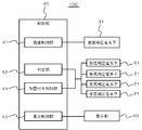
図2に示すように、携帯端末装置100は、発振用圧電素子31、受信用圧電素子21、触感付与用圧電素子81及び表示部60の他に、制御部40を有している。
制御部40は、発振用圧電素子31の動作を制御する発振制御部41と、判定部42と、表示部60の動作を制御する表示制御部43と、触感付与用圧電素子81の動作を制御する触感付与制御部44と、を有している。
発振制御部41により発振用圧電素子31を制御することにより、発振用圧電素子31から超音波を発振させることができる。
発振用圧電素子31により発振された超音波は、各受信用圧電素子21により検出される。各受信用圧電素子21は、発振用圧電素子31により発振された周波数の超音波を検出する。受信用圧電素子21の共振周波数は、発振用圧電素子31の発信周波数と一致していることが好ましい。
各受信用圧電素子21による検出結果は、それぞれ判定部42に入力される。
発振用圧電素子31により発振された超音波は、各受信用圧電素子21により検出される。各受信用圧電素子21は、発振用圧電素子31により発振された周波数の超音波を検出する。受信用圧電素子21の共振周波数は、発振用圧電素子31の発信周波数と一致していることが好ましい。
各受信用圧電素子21による検出結果は、それぞれ判定部42に入力される。
判定部42は、各受信用圧電素子21による検出結果に基づいて、何れの操作位置に対する操作が行われたかを判定する。
触感付与制御部44により各触感付与用圧電素子81を制御し、各触感付与用圧電素子81から操作位置に向けて超音波を発振させることにより、操作を行った物体(例えば指1(図3)或いはスタイラス(図示略)など)に対して触感を付与することができる。
図3に示すように、操作位置は、表示画面60aから離れた位置にある。操作位置は、例えば、各操作位置表示61~66の正面の空間にそれぞれ設定されている。図3には、一例として、操作位置表示62と対応する操作位置51に対して指1で操作する状態を示している。
発振用圧電素子31から出力された超音波は、指1で反射した後に各受信用圧電素子21により検出されるが、指1の位置に応じて、各受信用圧電素子21へ向けて反射される超音波の強度が異なる。つまり、何れの操作位置に対して操作が行われたかに応じて、各受信用圧電素子21による検出結果が異なる。このため、判定部42にて、各受信用圧電素子21による検出結果を解析することにより、何れの操作位置に対して操作が行われたかを判定することができる。すなわち、各操作位置表示に対応する操作位置に対して行われた操作を非接触式で検出することができる。
なお、このような検出動作を実現するために、例えば、判定部42は、予め、各操作位置毎に、各受信用圧電素子21による検出値をテーブルとして記憶している。そして、判定部42は、そのテーブルの中から、各受信用圧電素子21による検出値と対応する操作位置を抽出し、その操作位置に対する操作が行われたと判定する。
或いは、判定部42は、各受信用圧電素子21による検出値を用いた演算により、何れの操作位置に対して操作が行われたかを判定しても良い。例えば、表示画面60aの上に位置する受信用圧電素子21aによる検出値と、表示画面60aの下に位置する受信用圧電素子21bによる検出値との比から、操作位置の上下方向位置を判定し、表示画面60aの左に位置する受信用圧電素子21cによる検出値と、表示画面60aの右に位置する受信用圧電素子21dによる検出値との比から、操作位置の左右方向位置を判定することで、操作位置を特定しても良い。
なお、各操作位置は同一平面内に位置することが好ましく、これにより、ユーザによる操作が容易となる。また、表示画面60aから各操作位置までの距離は5cm以下(より好ましくは3cm以下)であることが好ましく、これにより、操作の検出をより高精度に行うことができる。
また、判定部42により、何れかの操作位置に対する操作が行われたと判定された場合、触感付与制御部44は、触感付与用圧電素子81を制御し、指1に超音波を当てさせることにより、指1に触感を付与する。ここで、各触感付与用圧電素子81から発振される超音波の位相の値(或いは、各触感付与用圧電素子81から発振される超音波の位相の相対的なずれ量の値)を制御することにより、指1などに触感を付与する位置を調節することができる。このため、本実施形態では、操作を検出した操作位置において触感を付与できるように、各触感付与用圧電素子81から発振される超音波の位相の値やその相対的なずれ量を制御する。
更に、各触感付与用圧電素子81から発振される超音波の振幅、位相の値(或いは、位相の相対的なずれ量)を制御することにより、複数種類の触感(例えば、固い触感、柔らかい触感、ざらざらの触感、つるつるした触感、凹凸の触感など)を付与することができる。
また、判定部42により何れかの操作位置に対する操作が行われたと判定された場合、制御部40は、その操作に応じたその他の処理を実行する。例えば、図1に示すように、操作位置表示61~66には、アプリの起動を指示する操作位置(図示略)を指し示す操作位置表示61、アドレス帳の起動を指示する操作位置51を指し示す操作位置表示62、電子メール機能の起動を指示する操作位置(図示略)を指し示す操作位置表示63、カメラ機能の起動を指示する操作位置(図示略)を指し示す操作位置表示64、電卓機能の起動を指示する操作位置(図示略)を指し示す操作位置表示65、及び、各種の設定機能の起動を指示する操作位置(図示略)を指し示す操作位置表示66が含まれ、制御部40は、これらの機能に応じた処理を実行する。
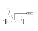
図4は発振用圧電素子31の模式図である。
発振用圧電素子31は、例えば、シート状の振動部材32と、振動子33と、支持部材34と、を備えている。振動子33は例えば圧電振動子であり、振動部材32の一方の面に取り付けられている。支持部材34は、振動部材32の縁を支持している。また、支持部材34は、例えば、携帯端末装置100の回路基板(図示略)或いは筐体101に固定されている。
発振制御部41は、振動子33に発振信号を入力することによって振動子33を振動させて、振動子33及び振動部材32より音波を発振させる発振回路を構成している。
発振制御部41は、振動子33に発振信号を入力することによって振動子33を振動させて、振動子33及び振動部材32より音波を発振させる発振回路を構成している。
振動部材32は、振動子33から発生した振動によって振動し、例えば周波数が20kHz以上の音波を発振する。なお、振動子33も、自身が振動することによって、例えば周波数が20kHz以上の音波を発振する。また振動部材32は、振動子33の基本共振周波数を調整する。機械振動子の基本共振周波数は、負荷重量と、コンプライアンスに依存する。コンプライアンスは振動子の機械剛性であるため、振動部材32の剛性を制御することで、振動子33の基本共振周波数を制御できる。なお、振動部材32の厚みは5μm以上500μm以下であることが好ましい。また、振動部材32は、剛性を示す指標である縦弾性係数が1Gpa以上500GPa以下であることが好ましい。振動部材32の剛性が低すぎる場合や、高すぎる場合は、機械振動子として特性や信頼性を損なう可能性が出てくる。なお、振動部材32を構成する材料は、金属や樹脂など、脆性材料である振動子33に対して高い弾性率を持つ材料であれば特に限定されないが、加工性やコストの観点からリン青銅やステンレスなどが好ましい。
本実施形態において振動子33の平面形状は円形である。ただし振動子33の平面形状は円形に限定されない。振動子33は、振動部材32に対向する面の全面が接着剤によって振動部材32に固定されている。これにより、振動子33の片面の全面が振動部材32によって拘束される。
発振制御部41は、振動子33に入力する電気信号、すなわち発振用圧電素子31における変調信号を生成する。変調信号の輸送波は、例えば、周波数が20kHz以上の超音波であり、具体的には、例えば100kHzの超音波である。発振制御部41は、所定の発振出力となるように発振用圧電素子31を制御する。
図5は、振動子33の厚さ方向の層構造を示す断面図である。振動子33は、圧電体36、上面電極37及び下面電極38を有している。
圧電体36は厚さ方向に分極している。圧電体36を構成する材料は、圧電効果を有する材料であれば、無機材料及び有機材料のいずれであってもよい。ただし、電気機械変換効率が高い材料、例えばジルコン酸チタン酸塩(PZT)やチタン酸バリウム(BaTiO3)であるのが好ましい。圧電体36の厚さh1は、例えば10μm以上1mm以下である。厚さh1が10μm未満の場合、発振用圧電素子31の製造時に振動子33が破損する可能性が生じる。また厚さh1が1mm超の場合、電気機械変換効率が低くなりすぎてしまい、十分な大きさの振動を得られない可能性がある。その理由は、振動子33の厚さが厚くなると、圧電振動子内における電界強度は反比例して小さくなるためである。
上面電極37及び下面電極38を構成する材料は特に限定されないが、例えば、銀や銀/パラジウムを使用することができる。銀は低抵抗で汎用的な電極材料として使用されているため、製造プロセスやコストなどに利点がある。銀/パラジウムは耐酸化に優れた低抵抗材料であるため、信頼性の観点から利点がある。また、上面電極37及び下面電極38の厚さh2は特に限定されないが、その厚さh2が1μm以上50μm以下であるのが好ましい。厚さh2が1μm未満では、上面電極37及び下面電極38を均一に成形することが難しくなり、その結果、電気機械変換効率が低下する可能性がある。また、上面電極37及び下面電極38の膜厚が100μmを超える場合は、上面電極37及び下面電極38が圧電体36に対して拘束面となり、エネルギー変換効率を低下させてしまう可能性が生じる。
振動子33は、外径=φ18mm、内径=φ12mm、厚み=100μmとすることができる。また上面電極37及び下面電極38としては、例えば厚み8μmの銀/パラジウム合金(重量比は例えば7:3)を用いることができる。また振動部材32は、外径=φ20mm、厚み=50μm(0.3mm)のリン青銅を用いることができる。支持部材34は発振用圧電素子31のケースとして機能するものであり、例えば、外径=φ22mm、内径=φ20mmの筒状(例えば円筒状)に形成されている。
図4は受信用圧電素子21の模式図である。
受信用圧電素子21は、発振用圧電素子31と同様に構成されている。各受信用圧電素子21の振動子33は、受信する超音波に応じた電気信号を個別に生成し、それら電気信号を(超音波の検出結果として)判定部42にそれぞれ出力する。
判定部42は、各受信用圧電素子21から入力される電気信号に基づいて、何れの操作位置に対する操作が行われたかを判定する。
このように、発振用圧電素子31は、超音波を出力するスピーカとしての機能を有するのに対し、受信用圧電素子21は、超音波を検出するマイクとして機能する。
また、図示は省略するが、触感付与用圧電素子81及び触感付与制御部44も発振用圧電素子31及び発振制御部41と同様に構成されている。
以上において、発振制御部41、発振用圧電素子31、受信用圧電素子21及び判定部42により、各操作位置表示に対応する操作位置に対して行われた操作を非接触式で検出する検出部が構成されている。
次に、一連の動作を説明する。
図7は第1の実施形態の動作の流れを示すフローチャートである。携帯端末装置100は、図7の処理を所定時間毎に繰り返し行う。
先ず、ユーザが複数の操作位置表示61~66により示される操作位置(操作位置51等)のうちの何れかの操作位置に対して操作を行う。すなわち、所望の操作位置に指1を移動させる。すると、検出部がその操作を検出する(ステップS11のY)。
次に、触感付与制御部44により、指1に触感を付与させる処理を行う(ステップS12)。
また、ステップS12と並行して(或いは、ステップS12に続いて)、ステップS13の処理を行う。ステップS13では、操作に応じたその他の処理(ステップS12での処理を除く処理)を行う。具体的には、例えば、アプリ、アドレス帳、電子メール機能、カメラ機能、電卓機能、各種の設定機能などを起動させる処理を行う。
以上のような第1の実施形態によれば、表示部60に表示された操作位置表示61~66により示される操作位置(操作位置51等)に対して行われた操作を非接触式で検出することができる。
よって、指やスタイラス等を画面に直接接触させるタッチパネルとは異なり、画面が手の脂などで汚れたり、画面にスタイラスの跡が残ったりすることを抑制できる。
よって、指やスタイラス等を画面に直接接触させるタッチパネルとは異なり、画面が手の脂などで汚れたり、画面にスタイラスの跡が残ったりすることを抑制できる。
また、発振用圧電素子31と受信用圧電素子21とのうちの少なくとも何れか一方(例えば受信用圧電素子21)を複数有するので、2次元的に複数箇所に配置された操作位置に対する操作をそれぞれ容易に検出することができる。
より具体的には、発振用圧電素子31と受信用圧電素子21とのうちの少なくとも何れか一方(例えば受信用圧電素子21)が、表示部60の4辺のそれぞれと対応する位置に配置されていることにより、2次元的に複数箇所に配置された操作位置に対する操作をそれぞれ容易に検出することができる。
より具体的には、発振用圧電素子31と受信用圧電素子21とのうちの少なくとも何れか一方(例えば受信用圧電素子21)が、表示部60の4辺のそれぞれと対応する位置に配置されていることにより、2次元的に複数箇所に配置された操作位置に対する操作をそれぞれ容易に検出することができる。
また、操作位置に向けて超音波を発振する触感付与用圧電素子81と、触感付与用圧電素子81を用いて、操作を行った物体(指1など)に対し、超音波により触感を付与させる制御を行う触感付与制御部44と、を有する。よって、表示画面60aに対して非接触式で操作を検出する場合にも、触れたかのような感触をユーザに与えることができるので、ユーザは、操作を行ったことを容易に認識することができる。
また、複数の触感付与用圧電素子81を用いて触感を付与することにより、その触感を付与する位置を容易に調節することができるため、操作位置において触感を付与することができる。
〔第2の実施形態〕
図8は第2の実施形態に係る入力装置としての携帯端末装置100のブロック図である。上記の第1の実施形態では、触感付与用圧電素子81を用いて触感を付与する例を説明したが、第2の実施形態では、発振用圧電素子31と受信用圧電素子21とのうちの少なくとも何れか1つの圧電素子(例えば、受信用圧電素子21)を用いて触感を付与する。より具体的には、受信用圧電素子21を用いて操作を検出するタイミングと、受信用圧電素子21を用いて触感を付与するタイミングとをずらすことにより(時分割することにより)、受信用圧電素子21を操作検出用と触感付与用に兼用させることができる。
図8は第2の実施形態に係る入力装置としての携帯端末装置100のブロック図である。上記の第1の実施形態では、触感付与用圧電素子81を用いて触感を付与する例を説明したが、第2の実施形態では、発振用圧電素子31と受信用圧電素子21とのうちの少なくとも何れか1つの圧電素子(例えば、受信用圧電素子21)を用いて触感を付与する。より具体的には、受信用圧電素子21を用いて操作を検出するタイミングと、受信用圧電素子21を用いて触感を付与するタイミングとをずらすことにより(時分割することにより)、受信用圧電素子21を操作検出用と触感付与用に兼用させることができる。
本実施形態の場合、各受信用圧電素子21は、触感付与制御部44の制御下で超音波を発振し、この超音波により、指1などに触感を付与する。
このような第2の実施形態によっても、第1の実施形態と同様の効果が得られる。
また、発振用圧電素子31と受信用圧電素子21とのうちの少なくとも何れか1つの圧電素子を用いて、操作を行った物体(例えば指1)に対し、超音波により触感を付与する。よって、検出用の圧電素子と、触感付与用の圧電素子とを兼用させることにより、携帯端末装置100の大型化を抑制することができる。
〔第3の実施形態〕
図9は第3の実施形態に係る入力装置としての携帯端末装置100を示す正面図である。上記の第1の実施形態では、表示部60の4辺のそれぞれに沿って受信用圧電素子21が配置されている例を説明した。これに対し、第3の実施形態では、図9に示すように、表示部60の2辺に沿って、それぞれ複数個の受信用圧電素子21が配列されている。このような第3の実施形態によっても、第1の実施形態或いは第2の実施形態と同様の効果が得られる。
図9は第3の実施形態に係る入力装置としての携帯端末装置100を示す正面図である。上記の第1の実施形態では、表示部60の4辺のそれぞれに沿って受信用圧電素子21が配置されている例を説明した。これに対し、第3の実施形態では、図9に示すように、表示部60の2辺に沿って、それぞれ複数個の受信用圧電素子21が配列されている。このような第3の実施形態によっても、第1の実施形態或いは第2の実施形態と同様の効果が得られる。
なお、上記の各実施形態では、入力装置が携帯端末装置である例を説明したが、入力装置はATM(Automated teller machine)などの据え付け型の装置であっても良い。
また、入力装置には、発振用圧電素子31を複数設けても良い。
また、入力装置には、発振用圧電素子31を複数設けても良い。
また、触感付与制御部44は、操作を行った物体の位置が、表示部60(表示画面60a)を含む面に近いほど、触感が強くなるように、触感付与用圧電素子81(或いは、発振用圧電素子31又は受信用圧電素子21)を制御するようにしても良い。このためには、判定部42は、受信用圧電素子21による検出結果に基づいて、操作を行った物体と、表示部60(表示画面60a)を含む面と、の距離を判定する。そして、触感付与制御部44は、その判定された距離が近いほど、触感が強くなるように、触感付与用圧電素子81(或いは、発振用圧電素子31又は受信用圧電素子21)を制御する。
この出願は、2011年1月26日に出願された日本出願特願2011-013971号を基礎とする優先権を主張し、その開示の全てをここに取り込む。
Claims (8)
- 複数の操作位置表示を行う表示部と、
前記複数の操作位置表示の各々に対応して入力装置の正面の特定の空間に設定された操作位置に対する操作を非接触式で検出する検出部と、
を有し、
前記検出部は、
前記入力装置の正面の空間に向けて超音波を発振する第1圧電素子と、
前記第1圧電素子より発振された前記超音波を検出する第2圧電素子と、
前記第2圧電素子による検出結果に基づいて、何れの前記操作位置に対する操作が行われたかを判定する判定部と、
を有することを特徴とする入力装置。 - 前記第1圧電素子と前記第2圧電素子とのうちの少なくとも何れか一方を複数有することを特徴とする請求項1に記載の入力装置。
- 前記表示部が矩形状であり、
前記第1圧電素子と前記第2圧電素子とのうちの少なくとも何れか一方が、前記表示部の4辺のそれぞれと対応する位置に配置されていることを特徴とする請求項2に記載の入力装置。 - 前記第2圧電素子を複数有することを特徴とする請求項2又は3に記載の入力装置。
- 前記表示部から前記特定の空間までの距離が5cm以下であることを特徴とする請求項1乃至4の何れか一項に記載の入力装置。
- 前記操作位置に向けて超音波を発振する第3圧電素子と、
前記第3圧電素子を用いて、前記操作を行った物体に対し、超音波により触感を付与させる制御を行う触感付与制御部と、
を有することを特徴とする請求項1乃至5の何れか一項に記載の入力装置。 - 前記第1圧電素子と前記第2圧電素子とのうちの少なくとも何れか1つの圧電素子を用いて、前記操作を行った物体に対し、超音波により触感を付与させる制御を行う触感付与制御部を有することを特徴とする請求項1乃至5の何れか一項に記載の入力装置。
- 当該入力装置は、携帯端末装置であることを特徴とする請求項1乃至7の何れか一項に記載の入力装置。
Priority Applications (3)
| Application Number | Priority Date | Filing Date | Title |
|---|---|---|---|
| EP12739793.3A EP2669775A4 (en) | 2011-01-26 | 2012-01-24 | INPUT DEVICE |
| CN201280006623.9A CN103329080B (zh) | 2011-01-26 | 2012-01-24 | 输入设备 |
| US13/980,206 US9348442B2 (en) | 2011-01-26 | 2012-01-24 | Input apparatus |
Applications Claiming Priority (2)
| Application Number | Priority Date | Filing Date | Title |
|---|---|---|---|
| JP2011-013971 | 2011-01-26 | ||
| JP2011013971A JP5924802B2 (ja) | 2011-01-26 | 2011-01-26 | 入力装置 |
Publications (1)
| Publication Number | Publication Date |
|---|---|
| WO2012102026A1 true WO2012102026A1 (ja) | 2012-08-02 |
Family
ID=46580601
Family Applications (1)
| Application Number | Title | Priority Date | Filing Date |
|---|---|---|---|
| PCT/JP2012/000436 WO2012102026A1 (ja) | 2011-01-26 | 2012-01-24 | 入力装置 |
Country Status (5)
| Country | Link |
|---|---|
| US (1) | US9348442B2 (ja) |
| EP (1) | EP2669775A4 (ja) |
| JP (1) | JP5924802B2 (ja) |
| CN (1) | CN103329080B (ja) |
| WO (1) | WO2012102026A1 (ja) |
Cited By (1)
| Publication number | Priority date | Publication date | Assignee | Title |
|---|---|---|---|---|
| JP2019185164A (ja) * | 2018-04-03 | 2019-10-24 | 富士通コンポーネント株式会社 | 触感提示装置 |
Families Citing this family (2)
| Publication number | Priority date | Publication date | Assignee | Title |
|---|---|---|---|---|
| US10890975B2 (en) * | 2016-07-22 | 2021-01-12 | Harman International Industries, Incorporated | Haptic guidance system |
| JP6938426B2 (ja) * | 2018-05-22 | 2021-09-22 | 京セラ株式会社 | 電子機器 |
Citations (3)
| Publication number | Priority date | Publication date | Assignee | Title |
|---|---|---|---|---|
| JPH07282699A (ja) | 1994-03-30 | 1995-10-27 | Whitaker Corp:The | 反射モード超音波接触感応スイッチ |
| JP2003029898A (ja) | 2001-07-16 | 2003-01-31 | Japan Science & Technology Corp | 触覚装置 |
| JP2004537118A (ja) * | 2001-07-22 | 2004-12-09 | トマー・シャリト・アクチボラゲット | コンピュータ化ポータブル携帯型手段 |
Family Cites Families (4)
| Publication number | Priority date | Publication date | Assignee | Title |
|---|---|---|---|---|
| CA2149213A1 (en) * | 1992-11-17 | 1994-05-26 | Thomas Debuisser | Method and device for capturing and processing graphical information |
| JP3206551B2 (ja) | 1998-06-12 | 2001-09-10 | 株式会社村田製作所 | 振動子およびそれを用いた振動ジャイロ |
| JP3929672B2 (ja) * | 2000-03-10 | 2007-06-13 | 独立行政法人科学技術振興機構 | 弾性波を用いたコンピュータ入出力装置 |
| GB0810179D0 (en) * | 2008-06-04 | 2008-07-09 | Elliptic Laboratories As | Object location |
-
2011
- 2011-01-26 JP JP2011013971A patent/JP5924802B2/ja active Active
-
2012
- 2012-01-24 CN CN201280006623.9A patent/CN103329080B/zh not_active Expired - Fee Related
- 2012-01-24 EP EP12739793.3A patent/EP2669775A4/en not_active Withdrawn
- 2012-01-24 US US13/980,206 patent/US9348442B2/en not_active Expired - Fee Related
- 2012-01-24 WO PCT/JP2012/000436 patent/WO2012102026A1/ja active Application Filing
Patent Citations (3)
| Publication number | Priority date | Publication date | Assignee | Title |
|---|---|---|---|---|
| JPH07282699A (ja) | 1994-03-30 | 1995-10-27 | Whitaker Corp:The | 反射モード超音波接触感応スイッチ |
| JP2003029898A (ja) | 2001-07-16 | 2003-01-31 | Japan Science & Technology Corp | 触覚装置 |
| JP2004537118A (ja) * | 2001-07-22 | 2004-12-09 | トマー・シャリト・アクチボラゲット | コンピュータ化ポータブル携帯型手段 |
Non-Patent Citations (1)
| Title |
|---|
| See also references of EP2669775A4 |
Cited By (1)
| Publication number | Priority date | Publication date | Assignee | Title |
|---|---|---|---|---|
| JP2019185164A (ja) * | 2018-04-03 | 2019-10-24 | 富士通コンポーネント株式会社 | 触感提示装置 |
Also Published As
| Publication number | Publication date |
|---|---|
| EP2669775A1 (en) | 2013-12-04 |
| CN103329080B (zh) | 2016-09-07 |
| US20130285967A1 (en) | 2013-10-31 |
| JP5924802B2 (ja) | 2016-05-25 |
| US9348442B2 (en) | 2016-05-24 |
| EP2669775A4 (en) | 2016-05-18 |
| CN103329080A (zh) | 2013-09-25 |
| JP2012155526A (ja) | 2012-08-16 |
Similar Documents
| Publication | Publication Date | Title |
|---|---|---|
| JP5343871B2 (ja) | タッチパネル装置、これを含むタッチパネル付き表示装置、及びタッチパネル装置の制御方法 | |
| JP5597583B2 (ja) | タッチパネル装置及び電子機器 | |
| JP5570640B2 (ja) | 圧電素子および電子機器 | |
| WO2015005103A1 (ja) | 振動デバイス及びそれを利用した電子機器 | |
| US8913027B2 (en) | Systems and methods for providing haptic feedback at multiple resonance frequencies | |
| US7616192B2 (en) | Touch device and method for providing tactile feedback | |
| JP5615421B2 (ja) | 電子機器 | |
| US20100141408A1 (en) | Audio amplifier apparatus to drive a panel to produce both an audio signal and haptic feedback | |
| WO2015059887A1 (ja) | 電子機器 | |
| KR20140109292A (ko) | 선형 공진 액추에이터를 구비한 햅틱 디바이스 | |
| KR20050044412A (ko) | 피드백 발생을 위한 방법 및 장치 | |
| WO2015045064A1 (ja) | 駆動制御装置、電子機器、及び駆動制御方法 | |
| JP5822022B2 (ja) | 電子機器、及び駆動制御プログラム | |
| KR20110077637A (ko) | 햅틱 디바이스 구동용 압전 액추에이터 | |
| JP2010286986A (ja) | 携帯端末装置 | |
| JP2011146006A (ja) | 入力装置及び電子機器 | |
| WO2012102026A1 (ja) | 入力装置 | |
| KR20120115159A (ko) | 택타일 피드백 방법 및 장치 | |
| KR20210018703A (ko) | 표시 장치 | |
| US11369995B2 (en) | Method for controlling a mobile device | |
| JP2013020362A (ja) | 入力装置、表示装置、および機器 | |
| JP2010282665A (ja) | 入力装置および入力装置の制御方法 | |
| JP5956525B2 (ja) | 入力装置 | |
| JP6904222B2 (ja) | 駆動制御装置、電子機器、及び、駆動制御方法 | |
| JP2016095550A (ja) | 触感呈示装置 |
Legal Events
| Date | Code | Title | Description |
|---|---|---|---|
| 121 | Ep: the epo has been informed by wipo that ep was designated in this application |
Ref document number: 12739793 Country of ref document: EP Kind code of ref document: A1 |
|
| WWE | Wipo information: entry into national phase |
Ref document number: 2012739793 Country of ref document: EP |
|
| WWE | Wipo information: entry into national phase |
Ref document number: 13980206 Country of ref document: US |
|
| NENP | Non-entry into the national phase |
Ref country code: DE |