WO2012101731A1 - 非接触充電モジュール及びこれを用いた受信側及び送信側非接触充電機器 - Google Patents
非接触充電モジュール及びこれを用いた受信側及び送信側非接触充電機器 Download PDFInfo
- Publication number
- WO2012101731A1 WO2012101731A1 PCT/JP2011/007348 JP2011007348W WO2012101731A1 WO 2012101731 A1 WO2012101731 A1 WO 2012101731A1 JP 2011007348 W JP2011007348 W JP 2011007348W WO 2012101731 A1 WO2012101731 A1 WO 2012101731A1
- Authority
- WO
- WIPO (PCT)
- Prior art keywords
- charging module
- coil
- contact charging
- magnet
- side non
- Prior art date
Links
Images


Classifications
-
- H—ELECTRICITY
- H01—ELECTRIC ELEMENTS
- H01F—MAGNETS; INDUCTANCES; TRANSFORMERS; SELECTION OF MATERIALS FOR THEIR MAGNETIC PROPERTIES
- H01F38/00—Adaptations of transformers or inductances for specific applications or functions
- H01F38/14—Inductive couplings
-
- H—ELECTRICITY
- H02—GENERATION; CONVERSION OR DISTRIBUTION OF ELECTRIC POWER
- H02J—CIRCUIT ARRANGEMENTS OR SYSTEMS FOR SUPPLYING OR DISTRIBUTING ELECTRIC POWER; SYSTEMS FOR STORING ELECTRIC ENERGY
- H02J50/00—Circuit arrangements or systems for wireless supply or distribution of electric power
- H02J50/005—Mechanical details of housing or structure aiming to accommodate the power transfer means, e.g. mechanical integration of coils, antennas or transducers into emitting or receiving devices
-
- H—ELECTRICITY
- H02—GENERATION; CONVERSION OR DISTRIBUTION OF ELECTRIC POWER
- H02J—CIRCUIT ARRANGEMENTS OR SYSTEMS FOR SUPPLYING OR DISTRIBUTING ELECTRIC POWER; SYSTEMS FOR STORING ELECTRIC ENERGY
- H02J50/00—Circuit arrangements or systems for wireless supply or distribution of electric power
- H02J50/10—Circuit arrangements or systems for wireless supply or distribution of electric power using inductive coupling
- H02J50/12—Circuit arrangements or systems for wireless supply or distribution of electric power using inductive coupling of the resonant type
-
- H—ELECTRICITY
- H02—GENERATION; CONVERSION OR DISTRIBUTION OF ELECTRIC POWER
- H02J—CIRCUIT ARRANGEMENTS OR SYSTEMS FOR SUPPLYING OR DISTRIBUTING ELECTRIC POWER; SYSTEMS FOR STORING ELECTRIC ENERGY
- H02J50/00—Circuit arrangements or systems for wireless supply or distribution of electric power
- H02J50/70—Circuit arrangements or systems for wireless supply or distribution of electric power involving the reduction of electric, magnetic or electromagnetic leakage fields
-
- H—ELECTRICITY
- H02—GENERATION; CONVERSION OR DISTRIBUTION OF ELECTRIC POWER
- H02J—CIRCUIT ARRANGEMENTS OR SYSTEMS FOR SUPPLYING OR DISTRIBUTING ELECTRIC POWER; SYSTEMS FOR STORING ELECTRIC ENERGY
- H02J50/00—Circuit arrangements or systems for wireless supply or distribution of electric power
- H02J50/90—Circuit arrangements or systems for wireless supply or distribution of electric power involving detection or optimisation of position, e.g. alignment
-
- H—ELECTRICITY
- H01—ELECTRIC ELEMENTS
- H01F—MAGNETS; INDUCTANCES; TRANSFORMERS; SELECTION OF MATERIALS FOR THEIR MAGNETIC PROPERTIES
- H01F7/00—Magnets
- H01F7/02—Permanent magnets [PM]
- H01F7/0231—Magnetic circuits with PM for power or force generation
- H01F7/0247—Orientating, locating, transporting arrangements
-
- H—ELECTRICITY
- H02—GENERATION; CONVERSION OR DISTRIBUTION OF ELECTRIC POWER
- H02J—CIRCUIT ARRANGEMENTS OR SYSTEMS FOR SUPPLYING OR DISTRIBUTING ELECTRIC POWER; SYSTEMS FOR STORING ELECTRIC ENERGY
- H02J7/00—Circuit arrangements for charging or depolarising batteries or for supplying loads from batteries
- H02J7/0042—Circuit arrangements for charging or depolarising batteries or for supplying loads from batteries characterised by the mechanical construction
Definitions
- the present invention relates to a non-contact charging module having a planar coil portion made of a spiral conductor and a magnetic sheet, and a receiving-side and transmitting-side non-contact charging device using the same.
- the main device such as the portable terminal device and the charger are required to be thin and small.
- a planar coil portion as a transmitting-side non-contact charging module or a receiving-side non-contact charging module and a magnetic sheet as in (Patent Document 1).
- the position of the primary side contactless charging module (transmitting side contactless charging module) and the position of the secondary side contactless charging module (receiving side contactless charging module) need to be accurately aligned. is there. This is to efficiently perform electromagnetic induction for power transmission.
- a method of using a magnet as one of methods for accurately aligning the primary side non-contact charging module (transmission side non-contact charging module) and the secondary side non-contact charging module (receiving side non-contact charging module). . This is because the magnet is mounted on at least one of the primary side non-contact charging module or the secondary side non-contact charging module, and the mutual magnets or one magnet and the other magnetic sheet are attracted to perform alignment. Is the method.
- a convex part is formed on the charging surface of a charger equipped with a primary side non-contact charging module
- a concave part is formed in an electronic device equipped with a secondary side non-contact charging module
- the convex part is fitted into the concave part.
- This is a method of performing physical (shape) forced alignment.
- the primary side non-contact charging module detects the position of the coil of the secondary side non-contact charging module so that the coil of the primary side non-contact charging module is automatically It is a method of moving to a position.
- it is a method in which the portable device can be charged anywhere on the charging surface of the charger by providing the charger with a large number of coils.
- the L value of the coil provided in each non-contact charging module varies greatly depending on whether or not a magnet is used for positioning the primary-side non-contact charging module and the secondary-side non-contact charging module. To do.
- the electromagnetic induction for power transmission uses the L value of the coil provided in each non-contact charging module to determine its resonance frequency.
- the present invention uses and does not use the magnet provided in the counterpart non-contact charging module for alignment of the primary non-contact charging module and the secondary non-contact charging module.
- a non-contact charging module that suppresses a change in the L value of the coil provided in the non-contact charging module and can be used in both cases of using and not using a magnet, and the same are used.
- An object of the present invention is to provide a non-contact charging device on the receiving side and transmitting side.
- the present invention has a case where a magnet provided in the counterpart non-contact charging module is used and a case where the magnet is not used in positioning with the counterpart non-contact charging module.
- the contact charging module comprising: a planar coil portion around which a conductive wire is wound; and a magnetic sheet placed on the coil surface of the planar coil portion so as to face the coil surface of the planar coil portion, A hollow portion of the planar coil portion is larger than a magnet provided in the counterpart non-contact charging module.
- the present invention either the case where the magnet provided in the counterpart non-contact charging module is used for the alignment of the primary non-contact charging module and the secondary non-contact charging module or the case where the magnet is not used is used.
- the L value of the coil provided in the non-contact charging module is not changed, a non-contact charging module capable of efficient alignment and power transmission in both cases of using a magnet and not using it. Can be provided.
- the block diagram which shows the non-contact electric power transmission apparatus in embodiment of this invention The figure which shows the structure of the non-contact charger in embodiment of this invention
- the figure which shows the primary side non-contact charge module in embodiment of this invention Detailed drawing which shows the primary side non-contact charge module in the form of execution of this invention
- the figure which shows the structure of the portable terminal device in embodiment of this invention The figure which shows the secondary side non-contact charge module in embodiment of this invention Detailed view showing a secondary side non-contact charging module in an embodiment of the present invention
- the figure which shows the relationship between a primary side non-contact charge module provided with a magnet, and a secondary side non-contact charge module The figure which shows the relationship between the internal diameter of a coil, and the L value of a coil
- the schematic diagram which shows the positional relationship of the magnet with which the non-contact charge module in embodiment of this invention was equipped with the other non-contact charge module which performs electric power transmission.
- the figure which shows the magnitude of the magnetic field which occurs in the rectangular plane coil part The figure which shows the result of having changed the thickness of the magnetic sheet of a present Example, and measuring L value of a plane coil part
- FIG. 1 is a block diagram showing a non-contact power transmission device according to an embodiment of the present invention.
- the non-contact power transmission device is composed of a primary-side non-contact charging module 1 (transmitting-side non-contact charging module) and a secondary-side non-contact charging module 2 (receiving-side non-contact charging module). Utilizing this, power is transmitted from the primary side non-contact charging module 1 to the secondary side non-contact charging module 2.
- This non-contact power transmission device is used for power transmission of about 5 W or less.
- the frequency of power transmission is about 110 to 205 kHz.
- the primary side non-contact charging module 1 is mounted on, for example, a charger
- the secondary side non-contact charging module 2 is mounted on, for example, a mobile phone, a digital camera, a PC, or the like.
- the primary side non-contact charging module 1 includes a primary side coil 11a, a magnetic sheet 3, a resonance capacitor (not shown), and a power input unit 5.
- the power input unit 5 is connected to a commercial power supply 300 as an external power supply, receives power supply of about 100 to 240 V, converts it into a predetermined current (DC 12 V, 1 A), and supplies it to the primary coil 11 a.
- the primary coil 11a generates a magnetic field according to its shape, number of turns, and supplied current.
- the resonance capacitor is connected to the primary side coil 11a and determines the resonance frequency of the magnetic field generated from the primary side coil 11a according to the relationship with the primary side coil 11a. The electromagnetic induction action from the primary side non-contact charging module 1 to the secondary side non-contact charging module 2 is performed by this resonance frequency.
- the secondary side non-contact charging module 2 includes a secondary side coil 11b, a magnetic sheet 4, a resonance capacitor (not shown), a rectifier circuit 6, and a power output unit 7.
- the secondary side coil 11b receives the magnetic field generated from the primary side coil 11a, converts the magnetic field into a predetermined current by electromagnetic induction, and passes the rectifier circuit 6 and the power output unit 7 to the secondary side non-side. Output to the outside of the contact charging module 2.
- the rectifier circuit 6 rectifies a predetermined current that is an alternating current and converts it into a predetermined current that is a direct current (DC 5 V, 1.5 A).
- the power output unit 7 is an external output unit of the secondary side non-contact charging module 2, and power is supplied to the electronic device 200 connected to the secondary side non-contact charging module 2 through the power output unit 7. Do.
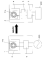
- FIG. 2 is a diagram showing a configuration of the non-contact charger according to the embodiment of the present invention.
- the non-contact charger shown in FIG. 2 is shown so that the inside can be understood.
- the non-contact charger 400 that transmits power using electromagnetic induction has the primary-side non-contact charging module 1 inside a case that constitutes its exterior.
- the non-contact charger 400 has a plug 401 that plugs into an outlet 301 of a commercial power supply 300 installed indoors or outdoors. By inserting the plug 401 into the outlet 301, the non-contact charger 400 can be supplied with power from the commercial power source 300.
- the non-contact charger 400 is installed on the desk 501, and the primary-side non-contact charging module 1 is disposed in the vicinity of the surface 402 opposite to the desk surface side of the non-contact charger 400. And the main plane of the primary side coil 11a in the primary side non-contact charge module 1 is arrange
- the non-contact charger 400 may be installed on a wall surface. In this case, the non-contact charger 400 is disposed in the vicinity of the surface opposite to the wall surface side.
- the primary side non-contact charging module 1 may have a magnet 30 a used for alignment with the secondary side non-contact charging module 2. In this case, it arrange
- FIG. 3 is a diagram showing the primary side non-contact charging module in the embodiment of the present invention, and shows a case where the primary side coil is a circular coil.
- a circular coil wound in a circle is described, but a rectangular coil wound in a substantially rectangular shape may be used.
- the primary side non-contact charge module demonstrated from now on, it applies to a secondary side non-contact charge module fundamentally. The difference of the secondary side non-contact charging module with respect to the primary side non-contact charging module will be described in detail later.
- the primary side non-contact charging module 1 includes a primary side coil 11a in which a conductive wire is wound in a spiral shape, and a magnetic sheet 3 provided so as to face the surface of the primary side coil 11a.
- the primary coil 11a includes a coil in which a conductor is wound in a radial direction so as to draw a vortex on the surface, and terminals 22a and 23a as current supply portions provided at both ends of the coil. Is provided. That is, the terminals 22a and 23a serving as current supply units supply current from the commercial power supply 300, which is an external power supply, to the primary coil 11a.
- a coil is obtained by winding a conductive wire in parallel on a plane, and a surface formed by the coil is called a coil surface.
- the thickness direction is the direction in which the primary coil 11a and the magnetic sheet 3 are stacked.
- the magnetic sheet 3 includes a flat portion 31a on which the primary coil 11a is placed, a central portion 32a in the central portion of the flat portion 31a and corresponding to a hollow region of the primary coil 11a, and a primary side. And a linear recess 33a into which a part of the lead wire of the coil 11a is inserted.
- the central portion 32a is formed with a recess or a through hole with respect to the flat portion 31a.
- the primary side coil 11a is wound outward from the inner diameter of 20 mm in diameter, and the outer diameter is 30 mm. That is, the primary coil 11a is wound in a donut shape.
- the primary side coil 11a may be wound in a circular shape or may be wound in a polygonal shape.
- the conducting wires are wound so as to leave a space between each other, the stray capacitance between the upper conducting wire and the lower conducting wire is reduced, and the AC resistance of the primary coil 11a can be kept small. Moreover, the thickness of the primary side coil 11a can be suppressed by winding so that space may be packed.
- the primary side non-contact charging module 1 may have a magnet 30 a used for alignment with the secondary side non-contact charging module 2.
- the magnet 30a is circular, the diameter is 15.5 mm or less, and the like.
- the magnet 30a has a coin shape and must be arranged so that the center thereof coincides with the winding center axis of the primary coil 11a. This is to reduce the influence of the magnet 30a on the primary coil 11a.
- examples of the alignment method include the following methods.
- a method for performing physical (formal) forced alignment such as forming a convex portion on the charging surface of the charger and fitting a concave portion on the electronic device on the secondary side, at least one of the primary side and the secondary side
- a method of automatically moving the coil to the position of the coil on the secondary side and a method of allowing the portable device to be charged anywhere on the charging surface of the charger by providing the charger with a large number of coils.
- the magnet is positioned without the primary side (charging side) non-contact charging module that includes the magnet and uses it for positioning.
- the primary side (charging side) non-contact charging module that is not used together, charging can be performed regardless of the type of the primary side (charging side) non-contact charging module, and convenience is improved.
- the other non-contact charging module is provided for alignment with the other non-contact charging module.
- the first method of arranging the magnet 30a is to arrange the magnet 30a on the upper surface of the central portion 32a of the magnetic sheet 3.
- a second method of arranging the magnet 30a there is a method of arranging the magnet 30a instead of the central portion 32a of the magnetic sheet 3. In the second method, since the magnet 30a is disposed in the hollow region of the coil, the primary side non-contact charging module 1 can be reduced in size.
- the magnet 30a shown in FIG. 3 is unnecessary.
- the magnet is provided in the hollow portion of the coil incorporated in at least one of the primary side non-contact charging module and the secondary side non-contact charging module.
- the magnet is circular, and in this case, the diameter of the magnet is smaller than the inner width of the coil.
- the magnet has a diameter of about 15.5 mm (about 10 mm to 20 mm) and a thickness of about 1.5 to 2 mm.
- a neodymium magnet is used, and the strength may be about 75 mT to 150 mT.
- the distance between the coil of the primary side non-contact charging module and the coil of the secondary side non-contact charging module is about 2 to 5 mm, sufficient alignment can be achieved with such a magnet. .
- the magnetic flux When a magnetic flux is generated between the primary side coil and the secondary side coil for power transmission, if there is a magnet between and around the magnetic flux, the magnetic flux extends to avoid the magnet. Alternatively, the magnetic flux penetrating through the magnet becomes eddy current or heat generation in the magnet, resulting in loss. Furthermore, when the magnet is disposed in the vicinity of the magnetic sheet, the magnetic permeability of the magnetic sheet in the vicinity of the magnet is lowered. Therefore, the magnet 30a provided in the primary side non-contact charging module 1 reduces the L value of both the primary side coil 11a and the secondary side coil 11b. As a result, the transmission efficiency between the non-contact charging modules decreases.
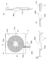
- FIG. 4 is a detailed view showing the primary-side non-contact charging module in the embodiment of the present invention.
- FIG. 4A is a top view of the primary side non-contact charging module
- FIG. 4B is a cross-sectional view taken along line AA of the primary side non-contact charging module in FIG. 4A.
- FIG. 4C is a cross-sectional view taken along the line BB of the primary side non-contact charging module in FIG.
- FIG. 4D is a BB cross-sectional view of the primary side non-contact charging module in FIG. 4A when a slit is provided.
- 4A and 4B show a case where the magnet 30a is not provided. In addition, when provided, the magnet 30a shown with the dotted line is provided.
- the primary side coil 11a extends from the winding start portion located in the central region of the primary side coil 11a to the terminal 23a. Is two steps in the thickness direction, and the remaining region is one step. At this time, the upper conductor and the lower conductor are wound so as to leave a space between each other, thereby reducing the stray capacitance between the upper conductor and the lower conductor, and the alternating current of the primary coil 11a. Resistance can be kept small.
- the number of turns of the primary coil 11a can be increased to increase the current flowing through the primary coil 11a.
- the conducting wire located in the upper stage and the conducting wire located in the lower stage are wound so as to close each other, thereby flowing the primary side coil 11a while suppressing the thickness of the primary side coil 11a. The current can be increased.
- the primary coil 11a is formed using a conducting wire having a circular cross section, but the conducting wire may be a conducting wire having a square cross section.
- the conducting wire may be a conducting wire having a circular cross-sectional shape, a gap is formed between adjacent conducting wires, so that the stray capacitance between the conducting wires is reduced, and the AC resistance of the primary coil 11a can be kept small.
- the primary side coil 11a is wound in one stage rather than being wound in two stages in the thickness direction, and the AC resistance of the primary side coil 11a is lowered, and the transmission efficiency can be increased. This is because when a conducting wire is wound in two stages, stray capacitance is generated between the upper conducting wire and the lower conducting wire. Therefore, it is better to wind as many portions as possible in one stage rather than winding the entire primary coil 11a in two stages. Moreover, it can reduce in thickness as the primary side non-contact charge module 1 by winding in 1 step
- the planar coil portion is composed of two conductors, the two conductors are electrically connected by solder or the like at the terminals 22a and 23a, so that the two conductors are one thick conductor.
- the two conducting wires may be wound in parallel with the coil surface, or may be wound in parallel with the coil surface. That is, in the case of being parallel to the coil surface, the two conducting wires are planar and are wound around the same center, and one conducting wire is sandwiched between the other conducting wires in the radial direction.
- thickness can be restrained by electrically joining two conducting wires in terminal 22a and 23a part, and making it function like one conducting wire. That is, for example, the cross-sectional area of a conducting wire having a diameter of 0.25 mm can be obtained by preparing two conducting wires having a diameter of 0.18 mm.
- the thickness of one turn of the coil is 0.25 mm and the radial width of the coil is 0.25 mm, but two conductors having a diameter of 0.18 mm. If it exists, the thickness of 1 turn of a coil will be 0.18 mm, and the width of radial direction will be 0.36 mm.
- the thickness direction is a stacking direction of the planar coil portion and the magnetic sheet 3. Further, only a part of the coil on the center side overlaps in two steps in the thickness direction, and the remaining outer part may have one step.
- the thickness of the primary-side non-contact charging module 1 is increased, but the current flowing through the planar coil portion can be increased by effectively increasing the cross-sectional area of the conducting wire, which is sufficient The number of turns can be easily secured.
- the primary side coil 11a is constituted by a conducting wire of about 0.18 to 0.35 mm, and among these, the primary side coil 11a of the primary side non-contact charging module 1 has a value of 0.00. A conductor of 25 to 0.35 mm is preferred.
- the alternating current resistance of the primary side coil 11a is low, the loss in the primary side coil 11a is prevented, and the power transmission efficiency of the primary side non-contact charging module 1 depending on the L value is improved by improving the L value. Can be improved.
- the primary coil 11a is formed in an annular shape (circular shape).
- the shape of the primary coil 11a is not limited to an annular shape (circular shape), and may be an elliptical shape, a rectangular shape, or a polygonal shape.
- the shape of the primary coil 11a is preferably annular (circular). This is because when the shape of the primary side coil 11a is annular (circular), power can be transmitted and received in a wider range, and therefore the primary side coil 11a and the secondary side non-contact of the primary side non-contact charging module 1 are possible. Positioning of the secondary coil 11b of the contact charging module 2 is facilitated. That is, in order to enable transmission / reception of power in a wider range, the secondary-side non-contact charging module 2 is less susceptible to the angle with respect to the primary-side non-contact charging module 1.
- terminals 22a and 23a may be close to each other or may be arranged apart from each other, it is easier to mount the primary side non-contact charging module 1 if they are arranged apart.
- the magnetic sheet 3 is provided in order to improve the power transmission efficiency of non-contact charging using electromagnetic induction action, and includes a flat portion 31a and a center corresponding to the inner diameter of the primary coil 11a. A portion 32a and a linear recess 33a are provided.
- the magnet 30a for positioning the primary side non-contact charging module 1 and the secondary side non-contact charging module 2 is provided, the magnet 30a may be disposed above the central portion 32a, or the magnet 30a may be disposed at the central portion. You may arrange
- the recessed part or the through-hole is provided in the part corresponding to the hollow part of the primary side coil 11a of the magnetic sheet 3.
- the magnetic sheet 3 a Ni—Zn ferrite sheet, a Mn—Zn ferrite sheet, a Mg—Zn ferrite sheet, or the like can be used.
- the magnetic sheet 3 may have a single-layer configuration, a configuration in which a plurality of the same materials are stacked in the thickness direction, or a plurality of different magnetic sheets may be stacked in the thickness direction. It is preferable that at least the magnetic permeability is 250 or more and the saturation magnetic flux density is 350 mT or more.
- An amorphous metal can also be used as the magnetic sheet 3.
- a ferrite sheet is used as the magnetic sheet 3
- the primary coil 11a can be made thin.
- the shape of the magnetic sheet 3 may be a circle, a rectangle, a polygon, a rectangle having a large curve at each corner, or a polygon.
- the secondary side coil 11b in the secondary side non-contact charging module 2 receives the magnetic field generated by the primary side non-contact charging module 1 and performs power transmission.
- a magnetic field may be generated so as to avoid the magnets, or the magnetic field trying to pass through the magnets may be lost.
- the magnetic permeability of the part near the magnet in the magnetic sheet 3 is reduced. That is, the magnetic field is weakened by the magnet. Therefore, in order to minimize the magnetic field weakened by the magnet, measures such as separating the primary coil 11a and the secondary coil 11b from the magnet and providing the magnetic sheet 3 that is not easily affected by the magnet are provided. It is necessary to take.
- FIG. 5 is a diagram showing the configuration of the mobile terminal device in the embodiment of the present invention, and is a perspective view when the mobile terminal device is disassembled.
- the portable terminal device 520 includes a liquid crystal panel 521, operation buttons 522, a substrate 523, a battery pack 524, and the like.
- a mobile terminal device 520 that receives power using electromagnetic induction is a mobile terminal device that includes a casing 525 that forms the exterior thereof and a secondary-side non-contact charging module 2 inside the casing 526.
- a substrate 523 provided with a control unit is provided on the back surface of the substrate 523.
- the battery pack 524 is connected to the substrate 523 and supplies power to the substrate 523.
- the secondary-side non-contact charging module 2 is provided on the back surface of the battery pack 524, that is, on the housing 526 side.
- the secondary side non-contact charging module 2 receives power supply from the primary side non-contact charging module 1 by electromagnetic induction action, and charges the battery pack 524 using the power.
- the secondary side non-contact charging module 2 includes a secondary side coil 11b, a magnetic sheet 4, and the like.
- the secondary coil 11b and the magnetic sheet 4 are disposed between the housing 526 and the substrate 523 in this order from the housing 526 side, so that the substrate 523 and the battery pack 524 are disposed.
- the power supply can be received with less influence.
- the magnetic sheet 4 appears to be disposed closer to the housing 526 than the secondary coil 11 b, but is schematically illustrated for the sake of clarity. As described above, the secondary coil 11b and the magnetic sheet 4 are arranged in this order from the housing 526 side.
- FIG. 6 is a diagram showing the secondary side non-contact charging module in the embodiment of the present invention, and shows a case where the secondary side coil is a circular coil.
- FIG. 7 is a detailed view showing the secondary side non-contact charging module in the embodiment of the present invention.
- 7A is a top view of the secondary side non-contact charging module
- FIG. 7B is a cross-sectional view of the secondary side non-contact charging module taken along the line CC in FIG. 7A.
- FIG. 7 (c) is a DD cross-sectional view of the secondary non-contact charging module in FIG. 7 (a) when a linear recess is provided.
- FIG. 7D is a DD cross-sectional view of the secondary-side non-contact charging module in FIG. 7A when a slit is provided.
- 7A and 7B show a case where the magnet 30b is not provided. In addition, when provided, the magnet 30b shown with the dotted line is provided.
- FIGS. 6 to 7 illustrating the secondary side non-contact charging module 2 correspond to FIGS. 3 to 4 illustrating the primary side non-contact charging module 1, respectively.
- the configuration of the secondary side non-contact charging module 2 is substantially the same as that of the primary side non-contact charging module 1.
- the secondary side non-contact charging module 2 is different from the primary side non-contact charging module 1 in the size and material of the magnetic sheet 4.
- the magnetic sheet 4 used for the secondary side non-contact charging module 2 has a size that fits within about 40 ⁇ 40 mm, and has a thickness of about 2 mm or less.
- the magnetic sheet 4 has a substantially square shape of about 33 mm ⁇ 33 mm. It is desirable that the magnetic sheet 4 be formed to be approximately the same or larger than the outer peripheral end of the secondary coil 11b.
- the shape of the magnetic sheet 3 may be a circle, a rectangle, a polygon, a rectangle having a large curve at each corner, or a polygon.
- the secondary-side non-contact charging module 2 is used in a mobile terminal as a power supply receiving side, there is no room in the space occupied by the secondary-side non-contact charging module 2 in the mobile terminal. Moreover, since the electric current which flows into the secondary side coil 11b of the secondary side non-contact charge module 2 is small, the insulation of the magnetic sheet 4 is not so required.
- the secondary side coil 11b is constituted by a conductive wire of about 0.18 to 0.35 mm, and among them, the secondary side coil 11b of the secondary side non-contact charging module 2 has a value of 0.0. A conducting wire of about 18 to 0.30 mm is suitable.
- the mounted electronic device When the mounted electronic device is a mobile phone, it is often arranged between a case constituting the exterior of the mobile phone and a battery pack located inside the case.
- a battery pack is an aluminum casing, it adversely affects power transmission. This is because an eddy current is generated in aluminum in a direction in which the magnetic flux generated by the coil is weakened, so that the magnetic flux of the coil is weakened. Therefore, it is necessary to provide the magnetic sheet 4 between the aluminum which is the exterior of the battery pack and the secondary coil 11b disposed on the exterior to reduce the influence on the aluminum.
- the relationship between the size of the magnet 30a and the size of the inner diameter of the primary coil 11a will be described.
- the magnet 30a is arrange
- the same relationship is realized also when the magnet 30b is arrange
- the magnet 30b corresponds to the magnet 30a.
- FIG. 8 is a diagram showing a relationship between a primary side non-contact charging module and a secondary side non-contact charging module including a magnet.
- FIG. 8A shows the case where the alignment magnet is used when the inner width of the coil is small
- FIG. 8B shows the case where the alignment magnet is used when the inner width of the coil is large.
- Is a case where the alignment magnet is not used when the inner width of the coil is small
- FIG. 8D is a case where the alignment magnet is not used when the inner width of the coil is large.
- the secondary side coil 11b of the secondary side non-contact charge module 2 which performs electric power transmission with the primary side non-contact charge module 1 provided with the magnet 30a is demonstrated.
- the description of the secondary side coil 11b related to the secondary side non-contact charging module 2 described below is based on the secondary side non-contact charging module 2 including the magnet 30b and the primary side non-contact charging that performs power transmission. This also applies to the primary coil 11a of the module 1. That is, the planar coil part of the non-contact charging module that enables positioning and power transmission in both cases where the other non-contact charging module that is the partner of power transmission includes a magnet and does not include a magnet will be described.
- FIG. 9 is a diagram showing the relationship between the inner diameter of the coil and the L value of the coil.
- the magnet 30a is contained only in the through hole of the primary side coil 11a, but the same can be said even if it is contained in the through hole of the secondary side coil 11b.
- the primary side coil 11a and the secondary side coil 11b are opposed to each other. Of the coils 11a and 11b, magnetic fields are also generated in the inner portions 211 and 212, and power is transmitted.
- the inner portions 211 and 212 are opposed to each other. Further, the inner portions 211 and 212 are also portions close to the magnet 30a, and are easily affected by the magnet 30a. That is, when a magnetic flux is generated between the primary side coil and the secondary side coil for power transmission, if a magnet exists between and around the primary side coil and the secondary side coil, the magnetic flux extends to avoid the magnet. Alternatively, the magnetic flux penetrating through the magnet becomes eddy current or heat generation in the magnet, resulting in loss.
- the magnet 30a provided in the primary side non-contact charging module 1 weakens the magnetic fluxes of the inner side portions 211 and 212 of the primary side coil 11a and the secondary side coil 11b, and has an adverse effect. As a result, the transmission efficiency between the non-contact charging modules decreases. Therefore, in the case of FIG. 8A, the inner portions 211 and 212 that are easily affected by the magnet 30a are enlarged. On the other hand, in FIG. 8C in which no magnet is used, the L value increases because the number of turns of the secondary coil 11b is large.
- the coil 30a having a small inner width may or may not be provided for alignment. In some cases, the L value reduction rate becomes very large. If the inner width of the secondary coil 11b is smaller than the diameter of the magnet 30a as shown in FIG. 8A, the secondary coil 11b is directly affected by the magnet 30a by an area facing the magnet 30a. End up. Accordingly, the inner width of the secondary coil 11b is preferably larger than the diameter of the magnet 30a.
- the non-contact charging module since the non-contact charging module is mounted on a charger or an electronic device, it cannot be formed in a size larger than a certain size. Therefore, if the inner width of the coils 11a and 11b is increased to reduce the adverse effect from the magnet 30a, the number of turns decreases, and the L value itself decreases regardless of the presence or absence of the magnet.
- the magnet 30a When the magnet 30a is circular, it is as follows. That is, when the outer diameter of the magnet 30a and the inner width of the coil 11b are substantially the same (the outer diameter of the magnet 30a is smaller than the inner width of the coil 11b by about 0 to 2 mm), the magnet 30a should be maximized. Therefore, the alignment accuracy of the primary side non-contact charging module and the secondary side non-contact charging module can be improved.
- the inner diameter of the coil 11b can be minimized, the number of turns of the coil 11b can be increased and the L value can be improved.
- the outer diameter of the magnet 30a is smaller than the inner width of the coil 11b (the outer diameter of the magnet 30a is smaller by about 2 to 8 mm than the inner width of the coil 11b), even if the alignment accuracy varies, the inner portion It is possible to prevent the magnet 30a from being present between the portions 211 and 212 that face each other.
- the outer diameter of the magnet 30a is 70% to 95% of the inner width of the coil 11b, it is possible to sufficiently cope with variations in alignment accuracy, and further, the primary side non-contact charging module and the secondary side non-contact The accuracy of alignment with the contact charging module can be improved. Further, the number of turns of the coil 11b can be ensured. This means that on the plane parallel to the planar coil portion, the area of the magnet 30a is 70% to 95% of the area of the through hole at the center of the planar coil portion.
- the non-contact charging module depending on the presence / absence of a magnet, whether or not the other non-contact charging module that is the partner of power transmission is provided with a magnet for alignment
- the fluctuation of the L value of the inner planar coil is reduced, and alignment and power transmission can be performed. That is, whether the primary side non-contact charging module 1 is provided with the magnet 30a or not, the secondary side non-contact charging module 2 is the primary side non-contact charging module in both cases. 1 and the power transmission can be efficiently performed.
- the primary side non-contact charging module 1 forms an LC resonance circuit using a resonance capacitor.
- the resonance frequency with the resonance capacitor also changes significantly. Since this resonance frequency is used for power transmission between the primary side non-contact charging module 1 and the secondary side non-contact charging module 2, if the resonance frequency changes greatly depending on the presence or absence of a magnet, power transmission cannot be performed correctly.
- power transmission is highly efficient.
- the number of turns of the secondary coil 11b is reduced to increase the inner diameter of the secondary coil 11b.
- the influence of the magnet 30a on the secondary coil 11b becomes smaller. That is, the L value of the secondary coil 11b is close to when the magnet 30a is used for positioning the primary side non-contact charging module 1 and the secondary side non-contact charging module 2 and when it is not used. Therefore, the resonance frequency when using the magnet 30a and when not using it is very close. At this time, the outer diameter of the coil is unified to 30 mm.
- the L value is 15 ⁇ H or more and the magnet 30a is used.
- the L value when not used can be made closer. The same can be said for the result of FIG. 9 as the L value of the primary side coil 11a of the primary side non-contact charging module 1 when the secondary side non-contact charging module 2 includes the magnet 30b.
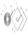
- FIG. 10 is a schematic diagram showing a positional relationship between magnets provided in the non-contact charging module and the other non-contact charging module that performs power transmission in the embodiment of the present invention. It has a magnet used for alignment of a secondary side non-contact charge module and a secondary side non-contact charge module.
- FIG. 10A shows a case where the secondary coil is a rectangular coil
- FIG. 10B shows a case where the secondary coil is a circular coil.
- the non-contact charging module described in these drawings is described by omitting a recess or a through hole that exists in the hollow portion of the coil portion of the magnetic sheet.
- the relationship between the magnet and the non-contact charging module is the relationship between the primary side non-contact charging module 1 and the magnet 30b provided in the secondary side non-contact charging module 2, and the secondary side non-contact charging module 2. This is true in both relations with the relation with the magnet 30a provided in the primary side non-contact charging module 1. Therefore, although the relationship between the secondary side non-contact charging module 2 and the magnet 30a provided in the primary side non-contact charging module 1 will be described as an example, the primary side non-contact charging module 1 and the secondary side non-contact charging are described. This also applies to the relationship with the magnet 30b provided in the module 2. That is, the influence of the magnet provided in the other non-contact charging module that is the partner of power transmission is suppressed, even if the other non-contact charging module is provided with a magnet, A contactless charging module capable of alignment and power transmission will be described.
- the secondary coil 11c shown in FIG. 10 (a) and the secondary coil 11b shown in FIG. 10 (b) are aligned so that the center thereof matches the center of the alignment magnet 30a. Even if the primary side non-contact charging module 1 does not include the magnet 30a, the secondary side non-contact charging module 2 may include a magnet.
- the positioning magnet 30a provided in the counterpart non-contact charging module has a circular shape with a diameter m, and the magnetic sheet 4 has a square shape.
- the magnetic sheet 4 may be a polygon other than a square, a rectangle, or a curved corner (corner). However, the magnetic sheet 4 can be reduced in size while ensuring the performance of the primary side non-contact charging module 1 that is the counterpart. Is preferably square.
- the positioning magnet 30a has been proposed as a standard for using the contactless charging modules 1 and 2 in order to ensure power transmission between the contactless charging modules 1 and 2 and to center the transmitting and receiving coils. used.
- the L value reduction rate of the secondary coil 11b or 11c can be reduced.
- the secondary coil is rectangular, when the diagonal dimension x inside the secondary coil 11c is the same value as the inner diameter y2 of the circular secondary coil 11b, the L value reduction rate of the secondary coil 11c is 2. It becomes substantially the same value as the secondary coil 11b.
- the magnetic sheet 4 is square and the secondary side coil 11c. Is preferably formed in a rectangular shape. Thereby, compared with a circular coil, the rectangular secondary side coil 11c can be kept away from the magnet 30a, and the rectangular secondary side coil 11c is not easily influenced by the magnet 30a. Moreover, although the magnetic flux concentrates on the corner part of the rectangular secondary side coil 11c, since the distance between the corner part and the magnet 30a can be ensured, the influence of the magnet 30a can be reduced.
- the entire secondary coil 11b exhibits substantially the same magnetic field strength.
- the diagonal dimension (x) of the rectangular secondary coil 11c is set to approximately 23 mm and the diameter (m) of the alignment magnet 30a is set to 15.5 mm ⁇ so as to satisfy the above-described relationship. did.
- the alignment magnet 30a is generally configured to have a maximum diameter of 15.5 mm and smaller. Considering miniaturization and positioning accuracy, the magnet 30a has a diameter of about 10 mm to 15.5 mm and a thickness of about 1.5 to 2 mm, so that positioning can be performed in a balanced manner. It is. Further, a neodymium magnet is used, and the strength may be about 75 mT to 150 mT.
- the distance between the coil of the primary side non-contact charging module and the coil of the secondary side non-contact charging module is about 2 to 5 mm, sufficient alignment can be achieved with such a magnet. . Therefore, if the secondary coil is wound in a circular shape, the diameter of the hollow portion is 15.5 mm or more, and if it is wound in a rectangular shape, the diagonal of the hollow portion is 15.5 mm or more, preferably the side of the hollow portion. By setting the width to 15.5 mm or more, basically, the influence of the magnet 30a can be reduced regardless of the size of the magnet 30a provided on the counterpart side.
- the rectangular coil is less susceptible to the influence of the magnet than the circular coil, but if both the primary side coil 11a and the secondary side coil 11b described later are rectangular coils, alignment during charging is performed. Sometimes you have to align each other's corners. Therefore, since it is difficult to align the angle at the time of alignment, it is preferable that one is a circular coil and the other is a rectangular coil. That is, the angle adjustment is not necessary, and the rectangular coil can further suppress the influence of the magnet.
- the primary-side non-contact charging module 1 or the secondary-side non-contact charging module 2 may include a rectangular coil, and any of them may include a circular coil. Since efficient power transmission is possible regardless of the shape, the primary-side non-contact charging module 1 may be provided with a circular coil.
- a rectangular coil is a coil whose corner R (the radius of the curve at the four corners) of the hollow part is 30% or less of the side width of the hollow part (y1 in FIG. 10 (a)).
- R the radius of the curve at the four corners
- the substantially rectangular hollow portion has curved corners.
- the strength of the conducting wire at the four corners can be improved by being slightly curved rather than perpendicular.
- R becomes too large, there is almost no change from the circular coil, and the effect unique to the rectangular coil cannot be obtained.
- the side width y1 of the hollow portion is 20 mm, for example, if the radius R of the curve at each corner is 6 mm or less, the influence of the magnet can be more effectively suppressed.
- the effect of the most rectangular coil described above can be obtained because the radius R of the curve at each corner is 5 to 30% of the side width of the substantially rectangular hollow portion. it can.
- FIG. 11 shows that there is no alignment magnet 30a when the diagonal dimension inside the rectangular planar coil part of FIG. 10 and the inner diameter dimension of the circular planar coil part are varied (the size of the magnetic sheet 4 is also changed accordingly).
- the L value reduction rate of the planar coil part when the alignment magnet 30a is provided for the case is shown. That is, the smaller the L value reduction rate, the smaller the influence of the alignment magnet.
- a present Example demonstrates the receiving side non-contact charging module as an example, it is applicable also to a transmitting side non-contact charging module.
- the larger the inner dimension of the coil the lower the L value reduction rate of the planar coil portion. This is because the influence of the alignment magnet 30a is reduced because an area in which an extra space between the alignment magnet 30a and the inside of the planar coil portion can be increased.
- the diagonal dimension inside the rectangular planar coil portion and the inner diameter dimension of the circular planar coil portion have the same value, the L value reduction rate of the planar coil portion also has the same value.
- the alignment with the inner side of the planar coil part is performed.
- the planar area of the planar coil portion is smaller in the rectangular planar coil portion than in the circular planar coil portion. Therefore, the diagonal dimension inside the rectangular planar coil portion can be increased so as to match the size of the magnetic sheet 4.
- the rectangular planar coil portion is located between the inner side of the planar coil portion and the outer periphery of the alignment magnet as compared with the circular planar coil portion.
- a gap can be created, and the influence of the alignment magnet can be reduced.
- the diagonal dimension (x) of the rectangular planar coil portion is set to approximately 23 mm and the diameter (m) of the alignment magnet 4 is set to 15 mm ⁇ so as to satisfy the above-described relationship.
- FIG. 12B is a cross-sectional view taken along the line AA ′ of FIG. 12A
- FIG. 12C is a cross-sectional view taken along the line BB ′ of FIG.
- the end portion of the alignment magnet and the inner end of the rectangular planar coil portion are close to each other, and the magnetic field generated in the rectangular planar coil portion is reduced due to the magnetic field of the alignment magnet.
- the end portion of the alignment magnet and the inner end of the rectangular planar coil portion are separated from each other, and the magnetic field generated in the rectangular planar coil portion is less affected by the magnetic field of the alignment magnet. Becomes bigger.
- the magnetic field generated in the circular planar coil portion is small everywhere on the circumference of the coil, that is, the L value of the circular planar coil portion that affects the mutual inductance of electromagnetic induction is small.
- the power transfer efficiency of the contact charging module is low.
- the generated magnetic field is large, that is, the L value of the rectangular planar coil portion that affects the mutual inductance of electromagnetic induction is larger than the L value of the circular planar coil portion, and thus is non-contact.
- the power transmission efficiency of the charging module is greatly improved compared to the circular planar coil portion.
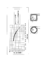
- FIG. 13 shows the result of measuring the L value of the planar coil portion by changing the ferrite thickness of the magnetic sheet 4.
- the L value is the inductance value of the planar coil portion, and the larger the value, the higher the power transmission efficiency of the non-contact charging module.
- the L value of the coil needs 6 to 8 ⁇ H.
- the magnetic field of the magnetic sheet 4 is increased due to the effect of the alignment magnet. The effect is reduced.
- the ferrite thickness of the magnetic sheet 4 needs to be 500 ⁇ m in order to generate a circular flat coil portion of 6 to 8 ⁇ H.
- the L value of the rectangular planar coil portion having the same ferrite thickness is 12 ⁇ H (arrow A).
- the L value of the rectangular planar coil portion is larger than that of the circular planar coil portion. Therefore, the magnetic field generated in the rectangular planar coil portion is large, and the power transmission efficiency of the non-contact charging module is increased.
- the ferrite thickness of the magnetic sheet 4 can be set thinner in the rectangular planar coil portion. That is, in order to set the target value of L to 6 to 8 ⁇ H, the ferrite thickness of the magnetic sheet 4 of the rectangular planar coil portion can be reduced to 300 ⁇ m (arrow B), and the ferrite thickness can be reduced. . Therefore, the thickness of the non-contact charging module can be reduced and the size can be easily reduced.
- the planar coil used by the non-contact charging module is made rectangular to avoid the influence of the magnetic field of the alignment magnet, and the power transmission efficiency of the non-contact charging module is improved, thereby reducing the size of the non-contact power receiving module. can do.
- the coil is not limited to being wound in a rectangular shape, and may be wound in a rectangular shape or a polygonal shape having an R at a corner. That is, the shape of the coil may be any shape as long as the entirety is on the magnetic sheet 4 and the inner edge of the coil has many portions away from the outer edge of the alignment magnet. Among them, the rectangular shape can obtain the above-described effects and can easily form a rectangular coil.
- the winding of the rectangular planar coil portion is described as a square, but is not limited to this and may be rectangular. That is, the above-described effect can be obtained if at least a part of the four inner sides of the coil is outside the outer periphery of the alignment magnet.
- the alignment magnet is not necessarily installed in both the non-contact charging module for power transmission and power reception, and may be installed on one side.
- the case where the alignment magnet is not installed in the non-contact charging module but is installed in the non-contact charging module which is the counterpart is described. Even if it exists, it can explain similarly.
- the data of the diagonal dimension of the rectangular coil (also called a square coil) in FIG. 11 is about 19 mm at the minimum.
- the distance between opposing sides of the hollow portion inside the rectangular coil is about 13.5 mm. Therefore, in FIG. 11, when the diagonal dimension of the rectangular coil is 19 mm, the alignment magnet having a diameter of 15.5 mm and the hollow portion inside the rectangular coil are somewhat covered. That is, when the hollow portion inside the rectangular planar coil portion is larger than the size of the alignment magnet, the L value reduction rate can be reduced.
- the rectangular coil is less susceptible to magnets than the circular coil.
- both the primary side coil and the secondary side coil are rectangular coils, each other during the alignment at the time of charging.
- the corners must be aligned. Therefore, since it is difficult to align the angles during alignment, it is preferable that one is a circular coil and the other is a rectangular coil. That is, the angle adjustment is not necessary, and the rectangular coil can further suppress the influence of the magnet.
- either the primary-side non-contact charging module or the secondary-side non-contact charging module may include a rectangular coil, and any of them may include a circular coil.
- the circular coil has a shape of a coil that is a partner of power transmission. However, since efficient power transmission is possible, it is preferable to provide a circular coil in the primary side non-contact charging module.
- the non-contact charging module is characterized in that the hollow portion inside the planar coil portion is larger than the size of the magnet.
- the transmitting side non-contact charging module and the receiving side non-contact charging module are aligned, for example, the transmitting side non-contact charging module ( It means that the magnet provided in the other non-contact charging module does not overlap the hollow part of the planar coil part of the receiving-side non-contact charging module.
- the magnet provided in the transmission-side contactless charging module does not protrude from the hollow portion of the reception-side contactless charging module to the coil surface. It means to fit in the hollow part.
- the transmission-side non-contact charging module and the non-contact charging device using the same when using a magnet for positioning the primary-side non-contact charging module and the secondary-side non-contact charging module.
- a magnet for positioning the primary-side non-contact charging module and the secondary-side non-contact charging module.
- it can be used with or without using a magnet. It is useful as a charging device on the transmitting side when charging a portable device such as a portable computer, a portable device such as a digital camera or a video camera.
Abstract
位置合わせのためのマグネットを用いても、特にコイルの内側部分に対するマグネットからの悪影響を防止し、電力伝送効率を向上させる非接触充電モジュール。この非接触充電モジュールは、マグネットを備える送信側非接触充電モジュールから、電磁誘導によって電力伝送される受信側非接触充電モジュールであって、導線がうずまき状に巻回された平面コイル部と、平面コイル部のコイルの面に対向するように設けられ、送信側非接触モジュールのマグネットと引き合う磁性シートと、を備え、平面コイル部の内径が、マグネットよりも大きいことを特徴とする。
Description
本発明は、渦巻状の導線からなる平面コイル部と磁性シートとを有する非接触充電モジュール及びこれを用いた受信側及び送信側非接触充電機器に関する。
近年、本体機器を充電器で非接触充電することのできるものが多く利用されている。これは、充電器側に送信側非接触充電モジュール、本体機器側に受信側非接触充電モジュールを配し、両モジュール間に電磁誘導を生じさせることにより充電器側から本体機器側に電力を伝送するものである。そして、上記本体機器として携帯端末機器等を適用することも提案されている。
この携帯端末機器等の本体機器や充電器は、薄型化や小型化が要望されるものである。この要望に応えるため、(特許文献1)のように、送信側非接触充電モジュールや受信側非接触充電モジュールとしての平面コイル部と、磁性シートとを備えることが考えられる。
この種の非接触充電モジュールは、1次側非接触充電モジュール(送信側非接触充電モジュール)の位置と2次側非接触充電モジュール(受信側非接触充電モジュール)の位置を正確に合わせる必要がある。これは、電力伝送のための電磁誘導を効率的に行うためである。
1次側非接触充電モジュール(送信側非接触充電モジュール)と2次側非接触充電モジュール(受信側非接触充電モジュール)を正確に位置合わせする方法の1つとして、マグネットを利用する方法がある。これは、1次側非接触充電モジュールもしくは2次側非接触充電モジュールの少なくとも一方にマグネットを搭載することで、お互いのマグネットもしくは一方のマグネットと他方の磁性シートとが引き付けあって位置合わせを行う方法である。
また、1次側非接触充電モジュールと2次側非接触充電モジュールを正確に位置合わせする他の方法として、マグネットを利用しないで位置合わせをする方法がある。
例えば、1次側非接触充電モジュールを搭載した充電器の充電面に凸部を形成し、2次側非接触充電モジュールを搭載した電子機器に凹部を形成し、凸部を凹部にはめ込むといった、物理的(形状的)に強制的な位置合わせを行う方法である。また、1次側非接触充電モジュールが2次側非接触充電モジュールのコイルの位置を検出することで、1次側非接触充電モジュールのコイルを自動的に2次側非接触充電モジュールのコイルの位置まで移動させる方法である。また充電器に多数のコイルを備えることで、携帯機器が充電器の充電面のどこにおいても充電可能とする方法である。
しかしながら、1次側非接触充電モジュールと2次側非接触充電モジュールの位置合わせにマグネットを使用する場合と使用しない場合とでは、それぞれの非接触充電モジュールに設けられたコイルのL値が大きく変化する。電力伝送のための電磁誘導は、それぞれの非接触充電モジュールに設けられたコイルのL値を利用して、その共振周波数が決定される。
そのため、1次側非接触充電モジュールと2次側非接触充電モジュールの位置合わせにマグネットを使用する場合と使用しない場合とでは、非接触充電モジュールを共用しにくいという問題があった。
そこで、本発明は、上記の問題に鑑み、1次側非接触充電モジュールと2次側非接触充電モジュールの位置合わせに相手側非接触充電モジュールに備えられたマグネットを使用する場合と使用しない場合のいずれの場合であっても、非接触充電モジュールに設けられたコイルのL値の変化を抑え、マグネットを使用する場合と使用しない場合のいずれの場合でも使用できる非接触充電モジュール及びこれを用いた受信側及び送信側非接触充電機器を提供することを目的とする。
上記課題を解決するために本発明は、相手側非接触充電モジュールとの位置合わせに際し、相手側非接触充電モジュールに備えられたマグネットを利用する場合と、マグネットを利用しない場合と、がある非接触充電モジュールにおいて、導線が巻回された平面コイル部と、前記平面コイル部のコイル面を載置し、前記平面コイル部のコイル面に対向するように設けられた磁性シートと、を備え、前記平面コイル部の中空部が、前記相手側非接触充電モジュールに備えられたマグネットよりも大きいことを特徴とするものである。
本発明によれば、1次側非接触充電モジュールと2次側非接触充電モジュールの位置合わせに相手側非接触充電モジュールに備えられたマグネットを使用する場合と使用しない場合のいずれの場合であっても、非接触充電モジュールに設けられたコイルのL値を変化させないので、マグネットを使用する場合と使用しない場合のいずれの場合にも効率的な位置合わせ及び電力伝送のできる非接触充電モジュールを提供することができる。
(実施の形態)
以下、本発明の実施の形態について図面をもちいて説明する。
以下、本発明の実施の形態について図面をもちいて説明する。
図1は、本発明の実施の形態における非接触電力伝送機器を示すブロック図である。
非接触電力伝送機器は、1次側非接触充電モジュール1(送信側非接触充電モジュール)と、2次側非接触充電モジュール2(受信側非接触充電モジュール)とから構成され、電磁誘導作用を利用して1次側非接触充電モジュール1から2次側非接触充電モジュール2に電力伝送が行われる。この非接触電力伝送機器は、約5W以下の電力伝送に使用される。また、電力伝送の周波数は約110~205kHzである。1次側非接触充電モジュール1は例えば充電器に搭載され、2次側非接触充電モジュール2は例えば携帯電話、デジタルカメラ、PC等に搭載される。
1次側非接触充電モジュール1は、1次側コイル11a、磁性シート3、共振コンデンサ(図示せず)、電力入力部5を備える。電力入力部5は、外部電源としての商用電源300に接続されて100~240V程度の電力供給を受け、所定電流(直流12V、1A)に変換して1次側コイル11aに供給する。1次側コイル11aは、その形状、巻数及び供給を受けた電流に応じた磁界を発生させる。共振コンデンサは、1次側コイル11aに接続され、1次側コイル11aとの関係により1次側コイル11aから発生させる磁界の共振周波数を決定する。1次側非接触充電モジュール1から2次側非接触充電モジュール2に対する電磁誘導作用は、この共振周波数により行われる。
一方、2次側非接触充電モジュール2は、2次側コイル11b、磁性シート4、共振コンデンサ(図示せず)、整流回路6、電力出力部7から構成される。2次側コイル11bは、1次側コイル11aから発生した磁界を受けて、その磁界を電磁誘導作用により所定電流に変換して、整流回路6、電力出力部7を介して、2次側非接触充電モジュール2の外部に出力する。整流回路6は、交流電流である所定電流を整流して直流電流である所定電流(直流5V、1.5A)に変換する。また、電力出力部7は2次側非接触充電モジュール2の外部出力部であり、この電力出力部7を介して、2次側非接触充電モジュール2に接続される電子機器200に電力供給を行う。
次に、1次側非接触充電モジュール1を非接触充電器に搭載する場合について説明する。
図2は、本発明の実施の形態における非接触充電器の構成を示す図である。なお、図2に示す非接触充電器は、その内部が分かるように示したものである。
電磁誘導作用を利用して電力を送信する非接触充電器400は、その外装を構成するケースの内部に1次側非接触充電モジュール1を有する。
非接触充電器400は、屋内もしくは屋外に設置された商用電源300のコンセント301に差し込むプラグ401を有する。このプラグ401をコンセント301に差し込むことによって、非接触充電器400は商用電源300から電力供給を受けることができる。
非接触充電器400は机上501に設置され、1次側非接触充電モジュール1は非接触充電器400の机面側とは反対側の面402の近傍に配置される。そして、1次側非接触充電モジュール1における1次側コイル11aの主平面を、非接触充電器400の机面側とは反対側の面402に平行に配置する。このようにすることで、2次側非接触充電モジュール2を搭載した電子機器の電力受信作業エリアを確保することができる。なお、非接触充電器400は壁面に設置されてもよく、この場合、非接触充電器400は壁面側とは反対側の面の近傍に配置される。
また、1次側非接触充電モジュール1は、2次側非接触充電モジュール2との位置合わせに用いるマグネット30aを有する場合がある。この場合、1次側コイル11aの中央領域に位置する中空部に配置される。
次に、1次側非接触充電モジュール1について説明する。
図3は、本発明の実施の形態における1次側非接触充電モジュールを示す図であり、1次側コイルが円形コイルの場合を示す。なお、図3においては円形に巻回された円形コイルにて説明しているが、略矩形状に巻回された矩形コイルであってもよい。なお、これから説明する1次側非接触充電モジュールの詳細については、基本的に2次側非接触充電モジュールに適応される。1次側非接触充電モジュールに対する2次側非接触充電モジュールの相違点は、詳しく後述する。
1次側非接触充電モジュール1は、導線が渦巻き状に巻回された1次側コイル11aと、1次側コイル11aの面に対向するように設けられた磁性シート3とを備える。
図3に示すとおり、1次側コイル11aは、面上で渦を描くように径方向に向けて導電体を巻いたコイルと、コイルの両端に設けられた電流供給部としての端子22a、23aを備える。すなわち、電流供給部としての端子22a、23aは、外部電源である商用電源300からの電流を1次側コイル11aに供給する。コイルは導線を平面上で平行に巻きまわしたものであり、コイルによって形成された面をコイル面と呼ぶ。なお、厚み方向とは、1次側コイル11aと磁性シート3との積層方向である。
また、磁性シート3は、1次側コイル11aを載置する平坦部31aと、平坦部31aの中心部にあって1次側コイル11aの中空領域内に相当する中心部32aと、1次側コイル11aの引き出し線の一部が挿入される直線凹部33aと、から構成されている。中心部32aは、平坦部31aに対して凹部あるいは貫通孔が形成されている。
本実施の形態における1次側非接触充電モジュール1では、1次側コイル11aは直径が20mmの内径から外に向かって巻回され、外径が30mmとなっている。すなわち、1次側コイル11aはドーナツ形状に巻回されている。なお、1次側コイル11aは円形に巻回されてもよいし、多角形に巻回されてもよい。
また、導線はお互いに空間を空けるように巻回されることによって、上段の導線と下段の導線との間の浮遊容量が小さくなり、1次側コイル11aの交流抵抗を小さく抑えることができる。また、空間を詰めるように巻回されることによって、1次側コイル11aの厚みを抑えることができる。
また、1次側非接触充電モジュール1は、2次側非接触充電モジュール2との位置合わせに用いるマグネット30aを有する場合がある。これは、規格(WPC)によって、マグネット30aは円形であること、直径が15.5mm以下であること等が定められている。マグネット30aはコイン形状をしており、その中心が1次側コイル11aの巻回中心軸と一致するように配置されなければならない。これは、1次側コイル11aに対するマグネット30aの影響を軽減させるためである。
すなわち、位置合わせの方法としては、例えば以下の方法が挙げられる。例えば充電器の充電面に凸部、2次側の電子機器に凹部を形成しはめ込むといった、物理的(形状的)に強制的な位置合わせを行う方法、少なくとも1次側及び2次側の一方にマグネットを搭載することで、お互いのマグネットもしくは一方のマグネットと他方の磁性シートとが引き付けあって位置合わせを行う方法、1次側が2次側のコイルの位置を検出することで、1次側のコイルを自動的に2次側のコイルの位置まで移動させる方法、充電器に多数のコイルを備えることで、携帯機器が充電器の充電面のどこにおいても充電可能とする方法等である。
このように、1次側(充電側)非接触充電モジュール及び2次側(被充電側)非接触充電モジュールのコイルの位置合わせには様々な方法が挙げられるが、マグネットを使用する方法とマグネットを使用しない方法とに分けられる。そして、1次側(充電側)非接触充電モジュールであれば、マグネットを備えた2次側(被充電側)非接触充電モジュール及びマグネットを備えていない2次側(被充電側)非接触充電モジュールの双方に適応できるようにすることで2次側(被充電側)非接触充電モジュールのタイプに関係せず充電ができ利便性が向上する。同様に、2次側(被充電側)非接触充電モジュールであれば、マグネットを備えてこれを位置あわせに使用する1次側(充電側)非接触充電モジュール及びマグネットを備えずにマグネットを位置あわせに使用しない1次側(充電側)非接触充電モジュールの双方に適応できるようにすることで1次側(充電側)非接触充電モジュールのタイプに関係せず充電ができ利便性が向上する。すなわち、電力伝送を行う相手である他方の非接触充電モジュールと電磁誘導によって電力伝送を行う非接触充電モジュールにおいて、他方の非接触充電モジュールとの位置合わせに際し、他方の非接触充電モジュールに備えられたマグネットを利用して位置合わせを行う場合、及びマグネットを利用しないで位置合わせを行う場合とがある非接触充電モジュールにおいて、電力伝送が良好に行えるように構成することが必要である。
1次側非接触充電モジュール1がマグネット30aを有する場合、マグネット30aを配置する1番目の方法として、マグネット30aを磁性シート3の中心部32aの上面に配置する方法がある。また、マグネット30aを配置する2番目の方法として、マグネット30aを磁性シート3の中心部32aの代わりに配置する方法がある。2番目の方法では、マグネット30aがコイルの中空領域に配置されるため、1次側非接触充電モジュール1を小型化できる。
なお、1次側非接触充電モジュール1と2次側非接触充電モジュール2の位置合わせにマグネットを利用しない場合は、図3に示すマグネット30aは必要ない。
ここで、マグネットが非接触充電モジュールの電力伝送効率に与える影響について説明する。一般的に、マグネットは1次側非接触充電モジュール及び2次側非接触充電モジュールの少なくとも一方において、内蔵されるコイルの中空部の中に設けられる。これにより、マグネットとマグネットまたはマグネットと磁性シート3をなるべく近接させることができると同時に、1次側及び2次側のコイルを近接させることができる。マグネットは円形であり、この場合、マグネットの直径はコイルの内幅よりも小さくなる。本実施の形態においてはマグネットの直径は約15.5mm(約10mm~20mm)であり、厚みは約1.5~2mmである。また、ネオジウム磁石を使用しており、強さは約75mTから150mT程度でよい。本実施の形態においては、1次側非接触充電モジュールのコイルと2次側非接触充電モジュールのコイルとの間隔が2~5mm程度であるので、この程度のマグネットで十分位置合わせが可能となる。
電力伝送のために1次側コイルと2次側コイルとの間に磁束が発生している際、その間や周辺にマグネットが存在すると磁束はマグネットを避けるように伸びる。もしくは、マグネットの中を貫く磁束はマグネットの中で渦電流や発熱となり、損失となる。更に、マグネットが磁性シートの近傍に配置されることによって、マグネット近傍の磁性シートの透磁率が低下してしまう。従って、1次側非接触充電モジュール1に備えられたマグネット30aは、1次側コイル11a及び2次側コイル11b双方のL値を低下させてしまう。その結果、非接触充電モジュール間の伝送効率が低下してしまう。
図4は、本発明の実施の形態における1次側非接触充電モジュールを示す詳細図である。図4(a)は1次側非接触充電モジュールの上面図、図4(b)は図4(a)における1次側非接触充電モジュールのA-A断面図である。図4(c)は、直線凹部を設けた場合の図4(a)における1次側非接触充電モジュールのB-B断面図である。図4(d)は、スリットを設けた場合の図4(a)における1次側非接触充電モジュールのB-B断面図である。なお、図4(a),図4(b)は、マグネット30aを備えない場合を示している。なお、備える場合には、点線で示したマグネット30aを備える。
1次側コイル11aは、1次側非接触充電モジュール1が装着される非接触充電器400の薄型化を達成するため、1次側コイル11aの中心領域に位置する巻始め部分から端子23aまでを厚さ方向に2段とし、残りの領域を1段とした。このとき、上段の導線と下段の導線どうしがお互いに空間を空けるように巻回されることによって、上段の導線と下段の導線との間の浮遊容量が小さくなり、1次側コイル11aの交流抵抗を小さく抑えることができる。
また、導線を積層して1次側コイル11aを1次側非接触充電モジュール1の厚み方向に伸ばす場合、1次側コイル11aの巻き数を増やして1次側コイル11aに流す電流を増加できる。導線を積層する際、上段に位置する導線と下段に位置する導線がお互いの空間を詰めるように巻回されることにより、1次側コイル11aの厚みを抑えつつ、1次側コイル11aに流す電流を増加できる。
なお、本実施の形態では、断面形状が円形状の導線を使用して1次側コイル11aを形成しているが、使用する導線は断面形状が方形形状の導線でもよい。断面形状が円形状の導線を使用する場合、隣り合う導線どうしの間に隙間が生じるため、導線間の浮遊容量が小さくなり、1次側コイル11aの交流抵抗を小さく抑えることができる。
また、1次側コイル11aは厚さ方向に2段で巻回するよりも1段で巻回した方が1次側コイル11aの交流抵抗が低くなり、伝送効率を高くすることができる。これは、2段で導線を巻回すると、上段の導線と下段の導線との間に浮遊容量が発生するためである。従って、1次側コイル11aは全体を2段で巻回するよりも、なるべく多くの部分を1段によって巻回した方がよい。また、1段で巻回することによって、1次側非接触充電モジュール1として薄型化することができる。なお、2本の導線で平面コイル部を構成する場合は、端子22a、23a部分において2本の導線が半田等によって電気的に接続されているので、2本の導線が1本の太い導線のようにしてもよい。2本の導線は、コイル面に対して平行に並んで巻回されてもよいし、コイル面に対して垂直に並んで巻回されてもよい。すなわち、コイル面に平行の場合は、2本の導線は平面状で同一の中心を軸に巻きまわされており、半径方向において一方の導線が他方の導線に挟まれるようになる。このように2本の導線を端子22a、23a部分で電気的に接合して1本の導線のように機能させることによって、同じ断面積であっても厚みを抑えることができる。すなわち、例えば、直径が0.25mmの導線の断面積を、直径が0.18mmの導線を2本準備することによって得ることができる。従って、直径が0.25mmの導線1本であると、コイルの1ターンの厚みは0.25mm、コイルの半径方向の幅は0.25mmであるが、直径が0.18mmの導線2本であると、コイルの1ターンの厚みは0.18mm、半径方向の幅は0.36mmとなる。なお、厚み方向とは、平面コイル部と磁性シート3との積層方向である。また、コイルは中心側の一部分のみ、厚さ方向に2段に重なっており、残りの外側の部分は1段としてもよい。また、コイル面に垂直の場合は、1次側非接触充電モジュール1の厚みが増加するが、導線の断面積が事実上増加することで平面コイル部を流れる電流を増加させることができ、十分な巻き数も容易に確保することができる。なお、本実施の形態では、約0.18~0.35mmの導線により1次側コイル11aを構成しており、その中でも1次側非接触充電モジュール1の1次側コイル11aには0.25~0.35mmの導線が好適である。
なお、1次側コイル11aの交流抵抗が低いことで1次側コイル11aにおける損失を防ぎ、L値を向上させることによって、L値に依存する1次側非接触充電モジュール1の電力伝送効率を向上させることができる。
また、本実施の形態では、1次側コイル11aは環状(円形状)に形成されている。1次側コイル11aの形状は環状(円形状)に限定されず、楕円形状、矩形状、多角形状でもよい。1次側非接触充電モジュール1と2次側非接触充電モジュール2の位置合わせを考慮すれば、1次側コイル11aの形状は環状(円形状)が好ましい。これは、1次側コイル11aの形状が環状(円形状)の場合、電力の送受信がより広範囲で可能となるため、1次側非接触充電モジュール1の1次側コイル11aと2次側非接触充電モジュール2の2次側コイル11bの位置合わせが容易になる。すなわち、電力の送受信をより広範囲で可能とするため、2次側非接触充電モジュール2は1次側非接触充電モジュール1に対する角度の影響を受けにくくなる。
なお、端子22a、23aはお互いに近接してもよく、離れて配置されてもよいが、離れて配置された方が1次側非接触充電モジュール1を実装しやすい。
磁性シート3は、電磁誘導作用を利用した非接触充電の電力伝送効率を向上させるために設けたものであって、平坦部31aと、中心であって1次側コイル11aの内径に相当する中心部32aと、直線凹部33aとを備える。また、1次側非接触充電モジュール1と2次側非接触充電モジュール2の位置合わせのマグネット30aを設ける場合、マグネット30aを中心部32aの上方に配置してもよいし、マグネット30aを中心部32aの代わりに配置してもよい。また、磁性シート3の1次側コイル11aの中空部に対応する部分に凹部または貫通孔が備えられている。
また、磁性シート3として、Ni-Zn系のフェライトシート、Mn-Zn系のフェライトシート、Mg-Zn系のフェライトシート等を使うことができる。磁性シート3は、単層構成としてもよいし、同一材料を厚み方向に複数枚積層した構成でもよいし、異なる磁性シートを厚み方向に複数枚積層してもよい。少なくとも、透磁率が250以上、飽和磁束密度が350mT以上のものであると好ましい。
また、アモルファス金属も磁性シート3として用いることができる。磁性シート3としてフェライトシートを使用する場合は1次側コイル11aの交流抵抗を低下させる点で有利となり、磁性シートとしてアモルファス金属を使用する場合は1次側コイル11aを薄型化することができる。また、磁性シート3の形状は、円形、矩形、多角形、四隅に大きな曲線を備える矩形及び多角形でもよい。
次に、マグネットが1次側非接触充電モジュール1及び後述する2次側非接触充電モジュール2に対して与える影響について説明する。1次側非接触充電モジュール1によって発生した磁界を2次側非接触充電モジュール2内の2次側コイル11bが受信して電力伝送を行う。ここで、1次側コイル11a及び2次側コイル11bの周辺にマグネットを配置すると、磁界がマグネットを避けるように発生するか、マグネットを通過しようとする磁界はなくなってしまうこともある。また、磁性シート3のうちマグネットに近い部分の透磁率が低下してしまう。すなわち、マグネットによって、磁界が弱められるのである。従って、マグネットによって弱められる磁界を最小限にするためには、1次側コイル11a及び2次側コイル11bとマグネットの距離を離す、マグネットの影響を受けにくい磁性シート3を備える、等の対策を講じる必要がある。
次に、2次側非接触充電モジュール2を携帯端末機器に搭載する場合について、説明する。
図5は、本発明の実施の形態における携帯端末機器の構成を示す図であり、携帯端末機器を分解した場合の斜視図である。
携帯端末機器520は、液晶パネル521、操作ボタン522、基板523、電池パック524等で構成されている。電磁誘導作用を利用して電力を受信する携帯端末機器520は、その外装を形成する筐体525と筐体526の内部に2次側非接触充電モジュール2を有する携帯端末機器である。
液晶パネル521、操作ボタン522が設けられた筐体525の裏面には、操作ボタン522から入力された情報を受信するともに必要な情報を液晶パネル521に表示して携帯端末機器520全体を制御する制御部を備える基板523が設けられている。また、基板523の裏面には電池パック524が設けられている。電池パック524は、基板523と接続されて基板523に電力供給を行う。
更に、電池パック524の裏面、すなわち筐体526側には2次側非接触充電モジュール2が設けられている。2次側非接触充電モジュール2は、電磁誘導作用により1次側非接触充電モジュール1から電力供給を受け、その電力を利用して電池パック524を充電する。
2次側非接触充電モジュール2は、2次側コイル11b、磁性シート4等から構成される。電力供給を受ける方向を筐体526側とする場合、筐体526と基板523との間で、筐体526側から順に2次側コイル11b、磁性シート4を配置すると、基板523と電池パック524の影響を軽減して電力供給を受けることができる。なお、図5においては、磁性シート4が2次側コイル11bよりも筐体526側に配置されているように見えるが、わかりやすくするために模式的に示したものであって、実際は、上述したとおり、筐体526側から2次側コイル11b、磁性シート4の順で配置される。
次に、2次側非接触充電モジュール2について説明する。
図6は、本発明の実施の形態における2次側非接触充電モジュールを示す図であり、2次側コイルが円形コイルの場合を示す。
図7は、本発明の実施の形態における2次側非接触充電モジュールを示す詳細図である。図7(a)は2次側非接触充電モジュールの上面図、図7(b)は図7(a)における2次側非接触充電モジュールのC-C断面図である。図7(c)は、直線凹部を設けた場合の図7(a)における2次側非接触充電モジュールのD-D断面図である。図7(d)は、スリットを設けた場合の図7(a)における2次側非接触充電モジュールのD-D断面図である。なお、図7(a),図7(b)は、マグネット30bを備えない場合を示している。なお、備える場合には、点線で示したマグネット30bを備える。
2次側非接触充電モジュール2を説明する図6~図7は、1次側非接触充電モジュール1を説明する図3~図4にそれぞれ対応する。2次側非接触充電モジュール2の構成は、1次側非接触充電モジュール1と略同一である。
2次側非接触充電モジュール2が1次側非接触充電モジュール1と異なる点として、磁性シート4の大きさと材料が挙げられる。2次側非接触充電モジュール2に用いる磁性シート4は、約40×40mm以内の大きさに収まる程度のサイズであり、厚みは約2mm以下である。
1次側非接触充電モジュール1に用いる磁性シート3と、2次側非接触充電モジュール2に用いる磁性シート4のサイズは異なる。これは、2次側非接触充電モジュール2が一般的にポータブル電子機器に搭載されるためであり、小型化が要求されるからである。本実施の形態において磁性シート4は略正方形の約33mm×33mmである。磁性シート4が2次側コイル11bの外周端よりも同程度または大きく形成されることが望ましい。また、磁性シート3の形状は、円形、矩形、多角形、四隅に大きな曲線を備える矩形及び多角形でもよい。
また、2次側非接触充電モジュール2は、電力供給の受信側として携帯端末に用いられるため、2次側非接触充電モジュール2の携帯端末内における占有スペースに余裕がない。また、2次側非接触充電モジュール2の2次側コイル11bに流れる電流は小さいため、磁性シート4の絶縁性はあまり要求されない。なお、本実施の形態では、約0.18~0.35mmの導線により2次側コイル11bを構成しており、その中でも2次側非接触充電モジュール2の2次側コイル11bには0.18~0.30mm程度の導線が好適である。
搭載される電子機器が携帯電話の場合、携帯電話の外装を構成するケースとその内部に位置する電池パックとの間に配置されることが多い。一般的に、電池パックはアルミニウムの筐体であるため、電力伝送に悪影響を与える。これは、コイルが発生させる磁束を弱める方向にアルミニウムに渦電流が発生するため、コイルの磁束が弱められることに起因する。そのため、電池パックの外装であるアルミニウムとその外装の上に配置される2次側コイル11bとの間に磁性シート4を設け、アルミニウムに対する影響を軽減する必要がある。
次に、マグネット30aのサイズと1次側コイル11aの内径のサイズとの関係について説明する。ここでは、1次側非接触充電モジュール1にマグネット30aを配置した場合について説明するが、2次側非接触充電モジュール2にマグネット30bを配置した場合も同様の関係が成り立つ。その場合は、マグネット30bはマグネット30aに相当する。
図8は、マグネットを備える1次側非接触充電モジュール及び2次側非接触充電モジュールの関係を示す図である。図8(a)はコイルの内幅が小さいときに位置合わせのマグネットを用いた場合、図8(b)はコイルの内幅が大きいときに位置合わせのマグネットを用いた場合、図8(c)はコイルの内幅が小さいときに位置合わせのマグネットを用いない場合、図8(d)はコイルの内幅が大きいときに位置合わせのマグネットを用いない場合である。なお、図8では、マグネット30aを備える1次側非接触充電モジュール1と電力伝送を行う2次側非接触充電モジュール2の2次側コイル11bについて説明する。しかしながら、下記で説明する2次側非接触充電モジュール2の関係の2次側コイル11bについての説明は、マグネット30bを備える2次側非接触充電モジュール2と電力伝送を行う1次側非接触充電モジュール1の1次側コイル11aについても適用される。すなわち、電力伝送の相手である他方の非接触充電モジュールがマグネットを備える場合と備えない場合との双方において、位置合わせ及び電力伝送が可能となる非接触充電モジュールの平面コイル部について説明する。図9は、コイルの内径とコイルのL値との関係を示す図である。
図中ではマグネット30aは1次側コイル11aの貫通孔内のみに収まっているが、2次側コイル11bの貫通孔内に収まっていても同様のことがいえる。
1次側コイル11aと2次側コイル11bは対向している。コイル11a、11bのうち、内側部分211、212においても磁界が発生し、電力伝送されるである。各内側部分211、212はそれぞれ対向している。また、内側部分211、212はマグネット30aに近い部分でもあり、マグネット30aからの悪影響を受けやすい。すなわち、電力伝送のために1次側コイルと2次側コイルとの間に磁束が発生している際、その間や周辺にマグネットが存在すると磁束はマグネットを避けるように伸びる。もしくは、マグネットの中を貫く磁束はマグネットの中で渦電流や発熱となり、損失となる。更に、マグネットが磁性シートの近傍に配置されることによって、マグネット近傍の磁性シートの透磁率が低下してしまう。従って、1次側非接触充電モジュール1に備えられたマグネット30aは、1次側コイル11a及び2次側コイル11bの特に内側部分211、212の磁束を弱めてしまい悪影響を及ぼす。その結果、非接触充電モジュール間の伝送効率が低下してしまう。従って、図8(a)の場合、マグネット30aの悪影響を受けやすい内側部分211、212が大きくなってしまう。それに対して、マグネットを用いない図8(c)は2次側コイル11bの巻き数が多いためL値は大きくなる。その結果、(c)におけるL値から図8(a)におけるL値へは大幅に数値が減少するため、内幅が小さいコイルでは、マグネット30aが位置合わせのために備えられる場合と備えられない場合とで、L値減少率が非常に大きくなってしまう。また、図8(a)のように2次側コイル11bの内幅がマグネット30aの直径よりも小さいと、マグネット30aと対向する面積だけ2次側コイル11bはダイレクトにマグネット30aの悪影響を受けてしまう。従って、2次側コイル11bの内幅はマグネット30aの直径よりも大きい方がよい。
対して、図8(b)のようにコイルの内幅が大きいと、マグネット30aの悪影響を受けやすい内側部分211、212が非常に小さくなる。また、マグネットを用いない図8(d)は2次側コイル11bの巻き数が少なくなるためL値は図8(c)に比べて小さくなる。その結果、図8(d)におけるL値から図8(b)におけるL値へは数値の減少が小さいため、内幅が大きいコイルではL値減少率を小さく抑えることができる。また、2次側コイル11bの内幅が大きいほど、マグネット30aからコイル11bの中空部の端部が離れるため、マグネット30aの影響を抑えることができる。しかしながら、非接触充電モジュールは充電器もしくは電子機器等に搭載されるため、ある一定以上の大きさに形成することができない。従って、コイル11a、11bの内幅を大きくしてマグネット30aからの悪影響を小さくしようとすると、巻き数が減ってしまいマグネット有り無しに関係せずL値そのものが減少してしまう。マグネット30aが円形の場合、以下のようになる。すなわち、マグネット30aの外径とコイル11bの内幅とがほぼ同一(マグネット30aの外径がコイル11bの内幅よりも0~2mm程度小さい)である場合、マグネット30aを最大限に大きくすることができるので、1次側非接触充電モジュールと2次側非接触充電モジュールとの位置合わせの精度が向上できる。また、コイル11bの内径を最小にすることができるので、コイル11bの巻き数が増大してL値を向上させることができる。また、マグネット30aの外径がコイル11bの内幅よりも小さい(マグネット30aの外径がコイル11bの内幅よりも2~8mm程度小さい)場合、位置合わせの精度にばらつきがあっても内側部分211、212が対向する部分の間にはマグネット30aが存在しないようにすることができる。このとき、マグネット30aの外径がコイル11bの内幅の70%~95%であることによって、位置合わせの精度にばらつきにも十分対応でき、更に1次側非接触充電モジュールと2次側非接触充電モジュールとの位置合わせの精度が向上できる。また、コイル11bの巻き数も確保することができる。これは、平面コイル部に平行な面において、マグネット30aの面積は、平面コイル部の中心の貫通孔の面積の70%~95%であることを意味する。このように構成することによって、電力伝送の相手である他方の非接触充電モジュールに位置合わせのためのマグネットを備える場合であっても備えない場合であっても、マグネットの有無による非接触充電モジュール内の平面コイルのL値の変動が小さくなり、位置合わせや電力伝送をすることができる。すなわち、1次側非接触充電モジュール1にマグネット30aを備えた場合であっても備えない場合であっても、2次側非接触充電モジュール2はどちらの場合も、1次側非接触充電モジュール1との位置合わせ及び電力伝送を効率よくすることができる。また、2次側非接触充電モジュール2にマグネット30bを備えた場合であっても備えない場合であっても、1次側非接触充電モジュール1はどちらの場合も、2次側非接触充電モジュール2との位置合わせ及び電力伝送を効率よくすることができる。そして、1次側コイル11aは1次側非接触充電モジュール1において、共振コンデンサをもちいてLC共振回路をつくる。このとき、マグネットを位置合わせに利用する場合と利用しない場合とでL値が大幅に変化すると、共振コンデンサとの共振周波数も大幅に変化してしまう。この共振周波数は、1次側非接触充電モジュール1と2次側非接触充電モジュール2との電力伝送に用いられるため、マグネットの有無によって共振周波数が大幅に変化すると正しく電力伝送ができなくなってしまうが、上記の構成とすることで、電力伝送が高効率化する。
更に、図9に示すように、マグネット30aのサイズ及び2次側コイル11bの外径を一定にした場合、2次側コイル11bの巻き数を減らして2次側コイル11bの内径を大きくしていくと、マグネット30aの2次側コイル11bに対する影響が小さくなる。すなわち、マグネット30aを1次側非接触充電モジュール1と2次側非接触充電モジュール2との位置合わせに利用する場合と利用しない場合における2次側コイル11bのL値が近い値となる。従って、マグネット30aを使用するときと使用しないときとの共振周波数が非常に近い値となる。なお、このとき、コイルの外径は30mmに統一している。また、1次側コイル11aの中空部端部とマグネット30aの外側端部との距離は、0mmより大きく、6mmよりも小さくすることで、L値を15μH以上としつつ、マグネット30aを利用する場合と利用しない場合でのL値を近づけることができる。図9の結果は、2次側非接触充電モジュール2にマグネット30bを備えた場合の1次側非接触充電モジュール1の1次側コイル11aのL値としても、同様のことがいえる。
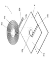
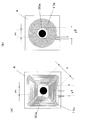
図10は、本発明の実施の形態における非接触充電モジュールと電力伝送を行う他方の非接触充電モジュールに備えられたマグネットの位置関係を示す模式図であり、1次側非接触充電モジュールに1次側非接触充電モジュールと2次側非接触充電モジュールの位置合わせに利用するマグネットを有するものである。なお、図10(a)は2次側コイルが矩形コイルの場合を示し、図10(b)は2次側コイルが円形コイルの場合を示す。また、これらの図で説明する非接触充電モジュールは、磁性シートのコイル部の中空部には存在する凹部あるいは貫通孔を省略して説明する。
このとき、マグネットと非接触充電モジュールとの関係は、1次側非接触充電モジュール1と2次側非接触充電モジュール2に設けられたマグネット30bとの関係と、2次側非接触充電モジュール2と1次側非接触充電モジュール1に設けられたマグネット30aとの関係との、双方の関係において当てはまる。従って、2次側非接触充電モジュール2と1次側非接触充電モジュール1に設けられたマグネット30aとの関係を例として説明するが、1次側非接触充電モジュール1と2次側非接触充電モジュール2に設けられたマグネット30bとの関係にも適用される。すなわち、電力伝送の相手である他方の非接触充電モジュールに備えられたマグネットの影響を抑え、他方の非接触充電モジュールにマグネットが備えられる場合であっても、備えられない場合であっても、位置合わせ及び電力伝送が可能である非接触充電モジュールについて説明する。
図10(a)に示す2次側コイル11c及び図10(b)に2次側コイル11bは、その中心が位置合わせのマグネット30aの中心と合うように位置合わせされる。また、1次側非接触充電モジュール1がマグネット30aを設けない場合であっても、2次側非接触充電モジュール2がマグネットを備えることもある。
相手側非接触充電モジュールが備える位置合わせのマグネット30aは直径mの円形状であり、磁性シート4は正方形である。なお、磁性シート4は正方形以外の多角形や矩形状、角に曲線(コーナー)であってもよいが、相手側である1次側非接触充電モジュール1の性能を確保しながら小型化するには正方形のほうが好ましい。
位置合わせのマグネット30aは、非接触充電モジュール1、2を使用するに当たって規格提案されているもので、非接触充電モジュール1、2間の電力伝送を確実にし、送受信コイルの中心合わせを行なうために使用される。
同じ巻線数の矩形の2次側コイル11cまたは円形の2次側コイル11bを同じ大きさの磁性シート4上に設置した場合、両者とも同一の面積の磁性シート4内に納まる。すなわち、図10(a)及び(b)に示す通り、同じ巻線数の矩形の2次側コイル11cまたは円形の2次側コイル11bを1辺の長さの磁性シート4上に設置した場合、矩形の2次側コイル11cの対向する内辺間の最短距離y1と円形の2次側コイル11bの内径y2を同じ長さにすることができる。
一方、矩形の2次側コイル11c内側の対角線長xは円形の2次側コイル11bの内径y2と同じ長さである矩形の2次側コイル11bの対向する内辺間の最短距離y1より長いxとなる。すなわち、矩形の2次側コイル11cでは、円形の2次側コイル11bに比べて位置合わせのマグネット30aと2次側コイル11cとの間隔を大きく取れる領域が多くなる。すなわち、x>y1、y1=y2の関係である。
そして、1次側非接触充電モジュール1または2次側非接触充電モジュール2に備えるマグネットの影響を抑えるためには、矩形のコイルはx>=m、好ましくはy1>=mとなる必要がある。
2次側コイル11bまたは11cと、位置合わせのマグネット30aとの間隔が大きくなると、位置合わせマグネット30aの影響が小さくなるため、2次側コイル11bまたは11cのL値減少率を小さくできる。2次側コイルが矩形の場合、2次側コイル11cの内側の対角線寸法xが円形の2次側コイル11bの内径寸法y2と同じ値のとき、2次側コイル11cのL値減少率が2次側コイル11bと略同じ値になる。
そのため、非接触充電器400の1次側非接触充電モジュール1を収納するスペースが方形状であり、しかもそのスペースが限られている場合には、磁性シート4を方形状として2次側コイル11cを矩形状に形成することが好ましい。これにより、円形コイルと比較して、矩形の2次側コイル11cをマグネット30aから遠ざけることができ、矩形の2次側コイル11cはマグネット30aからの影響を受けにくい。また、矩形の2次側コイル11cは、磁束がコーナー部に集中するが、そのコーナー部とマグネット30aとの距離を大きく確保できるため、マグネット30aの影響を軽減できる。
すなわち、2次側コイル11bが円形に巻回される場合は、2次側コイル11b全体がほぼ同じ磁界の強さを示す。しかし、2次側コイル11bが略矩形に巻回される場合は、その角部(コーナー)において磁界が集中する。従って、2次側コイル11cの内側の対角線寸法xが位置合わせマグネット30aの外径よりも外側に位置すること(x>=m)で、マグネット30aの影響を抑えて電力送信することができる。また、2次側コイル11bの対向する内辺間の最短距離y1が位置合わせマグネット30aの外径よりも外側に位置すること(y1>=m)で、2次側コイル11c全体が位置合わせマグネット30aの外径よりも外側に位置し、更に2次側コイル11bの角部(コーナー)がマグネット30aから一定距離を開けて位置することとなる。従って、よりマグネット30aが2次側コイル11bに与える影響を低減させることができる。
なお、本実施の形態では、前述した関係を満足するように矩形の2次側コイル11cの対角線寸法(x)をおよそ23mmにし、位置合わせのマグネット30aの径(m)を15.5mmφに設定した。位置合わせのマグネット30aは一般的に、15.5mmを最大の直径とし、それよりも小さく構成される。小型化と、位置合わせの精度を鑑みた場合に、マグネット30aの直径が約10mm~15.5mmであり、厚みは約1.5~2mmとなることでバランスよく位置合わせをすることができるからである。また、ネオジウム磁石を使用しており、強さは約75mTから150mT程度でよい。本実施の形態においては、1次側非接触充電モジュールのコイルと2次側非接触充電モジュールのコイルとの間隔が2~5mm程度であるので、この程度のマグネットで十分位置合わせが可能となる。従って、2次側コイルが円形状に巻回されていれば、中空部の直径を15.5mm以上、矩形に巻回していれば中空部の対角線を15.5mm以上、好ましくは中空部の辺幅を15.5mm以上とすることで、基本的に、相手側に備えられたマグネット30aの大きさに関わらずマグネット30aの影響を低減することができる。
上述したように、矩形コイルの方が円形コイルよりもマグネットの影響を受けにくいが、1次側コイル11a及び後述する2次側コイル11bの両方が矩形コイルであると、充電時の位置合わせの際にお互いのコーナーどうしの位置合わせをしなくてはならなくなる。従って、位置合わせの際の角度合わせが難しいため、一方が円形コイル、他方が矩形コイルであるとよい。すなわち、角度調整も必要なく、更に矩形コイルがマグネットの影響を抑えることができるためである。なお、1次側非接触充電モジュール1及び2次側非接触充電モジュール2のいずれが矩形コイルを備え、いずれが円形コイルを備えても構わないが、円形コイルは電力伝送の相手となるコイルの形状によらず効率的な電力伝送が可能であるため、1次側非接触充電モジュール1に円形コイルを備えるとよい。
なお、円形コイルに比較して、矩形コイルとは、中空部四隅の角のR(四隅の曲線の半径)が中空部の辺幅(図10(a)のy1)の30%以下のものをいう。すなわち、図10(a)において、略矩形の中空部は四隅が曲線状となっている。直角であるよりも、多少でも曲線であることで、四隅における導線の強度を向上させることができる。しかしながら、Rが大きくなりすぎると円形コイルとほとんど変化なく、矩形コイルならではの効果を得ることができなくなる。検討の結果、中空部の辺幅y1が例えば20mmであった場合、各四隅の曲線の半径Rが6mm以下であれば、マグネットの影響をより効果的に抑えることができることがわかった。また、前述したように四隅の強度まで考慮すると、各四隅の曲線の半径Rが略矩形の中空部の辺幅の5~30%であることによって、前述したもっとも矩形コイルの効果を得ることができる。
さらに非接触充電モジュールの矩形に巻回されたコイルの中空部とマグネットとの関係について説明する。
図11は、図10の矩形の平面コイル部内側の対角線寸法及び円形の平面コイル部の内径寸法を可変した(磁性シート4の大きさもそれに応じて変えている)時に、位置合わせマグネット30aが無い場合に対して位置合わせマグネット30aが有る場合の平面コイル部のL値減少率を示したものである。すなわち、L値減少率が少ないほど位置合わせマグネットの影響が小さいことを表している。なお、本実施例は一例として受信側非接触充電モジュールについて説明するが、送信側非接触充電モジュールにも適用できる。
図11に示す通り、コイルの内寸法が大きいほど平面コイル部のL値減少率が少ない。位置合わせマグネット30aと平面コイル部の内側との間隔を余分に取れる領域が多くなるので位置合わせマグネット30aの影響が小さくなるためである。一方、矩形の平面コイル部の内側の対角線寸法と円形の平面コイル部の内径寸法とが同じ値の場合には平面コイル部のL値減少率も同じ値である。
すなわち、矩形の平面コイル部の内側の対角線寸法x及び円形の平面コイル部の内径寸法yが位置合わせマグネットの直径mより大きいと(x=y>m)、平面コイル部の内辺と位置合わせマグネットの外周辺との間に隙間ができる。ところが、この場合平面コイル部の平面の面積は矩形の平面コイル部のほうが円形の平面コイル部に比較して小さい。そこで、磁性シート4の大きさに合うように矩形の平面コイル部の内側の対角寸法を大きくすることができる。そうすることで、磁性シート4内に平面コイル部を設置した場合矩形の平面コイル部のほうが円形の平面コイル部に比較して平面コイル部の内辺と位置合わせマグネットの外周辺との間に隙間が作ることができ、位置合わせマグネットの影響を小さくすることができる。本実施の形態では、前述した関係を満足するように矩形の平面コイル部の対角線寸法(x)をおよそ23mmにし、位置合わせマグネット4の径(m)を15mmΦに設定した。
次に、図12を用いて矩形の平面コイル部で発生する磁界の大きさについて説明する。図12(b)は図12(a)のA-A´断面図であり、図12(c)は図12(a)のB-B´断面図である。図12(b)においては、位置合わせマグネットの端部と矩形の平面コイル部の内端とが近接しており、位置合わせマグネットの磁界の影響により矩形の平面コイル部で発生する磁界は小さくなる。一方、図12(c)においては、位置合わせマグネットの端部と矩形の平面コイル部の内端とが離れており、位置合わせマグネットの磁界の影響を受けにくくなり矩形の平面コイル部で生じる磁界は大きくなる。
要するに、上述した円形の平面コイル部ではコイル円周のどこでも、円形の平面コイル部で生じる磁界は小さく、すなわち電磁誘導の相互インダクタンスに影響を与える円形の平面コイル部のL値は小さくなり、非接触充電モジュールの電力伝送効率は低い。一方、上述した矩形の平面コイル部では、生じる磁界は大きく、すなわち電磁誘導の相互インダクタンスに影響を与える矩形の平面コイル部のL値は円形の平面コイル部のL値より大きくなり、それで非接触充電モジュールの電力伝送効率は円形の平面コイル部に比べ大きく向上することになる。
次に、図10における矩形の平面コイル部と円形の平面コイル部で磁性シート4のフェライト厚みを変えて平面コイル部のL値を測定した結果について説明する。
図13は磁性シート4のフェライト厚みを変えて平面コイル部のL値を測定した結果を示している。ここでL値とは平面コイル部のインダクタンス値であり、その値が大きいほど非接触充電モジュールの電力伝送の効率が高くなる。
非接触充電モジュールの電力伝送の性能を満足させるには、コイルのL値は6~8μH必要であるが、位置合わせマグネットが有る場合には位置合わせマグネットの影響で磁性シート4の磁界強度アップの効果が低減する。
図13によると、位置合わせマグネットがある時には円形の平面コイル部が6~8μH発生するには磁性シート4のフェライト厚みは500μm必要である。それに比較し、同じフェライト厚みを持つ矩形の平面コイル部のL値は12μHとなる(矢印A)。
磁性シート4のフェライト厚みと面積が同一の条件下では矩形の平面コイル部のL値のほうが円形の平面コイル部に比べて大きい値になっている。したがって、矩形の平面コイル部で生じる磁界は大きく、非接触充電モジュールの電力伝送効率は大きくなることとなる。
矩形の平面コイル部と円形の平面コイル部のL値を同じにしようとした場合では矩形の平面コイル部のほうが磁性シート4のフェライト厚みを薄く設定することができる。すなわち、L値の目標値である6~8μHにするには、矩形の平面コイル部の磁性シート4のフェライト厚みを300μmにすることができ(矢印B)、フェライトの厚みを薄くすることができる。したがって、非接触充電モジュールの厚さを薄くすることができ、小型化しやすくなる。
このように、非接触充電モジュールの用いる平面コイルを矩形にすることで位置合わせマグネットの磁界の影響を避け、非接触充電モジュールの電力伝送効率を向上させることにより非接触受電モジュールの小型化を達成することができる。
なお、コイルは矩形に巻回されることに限定されず、角にRを有した方形状や多角形状に巻回される場合もある。すなわち、コイルの形状は、その全体が磁性シート4上にあって、コイルの内縁が位置合わせマグネットの外縁から離れる部分を多く有する形状であればよい。その中でも、矩形の形状は上述した効果を得られるとともに、矩形コイルを容易に作成することができるものである。
本実施の形態では、矩形の平面コイル部のコイルの巻回は正方形で説明しているが、これに限るわけではなく長方形でもよい。すなわち、コイルの4つの内辺の少なくとも一部が位置合わせマグネットの外周よりも外側にあれば、上述した効果が得られる。
なお、位置合わせマグネットは、必ずしも送電用と受電用の両方の非接触充電モジュール内に設置されているわけでは無く、片方に設置されている場合もある。本実施の形態では、位置合わせマグネットは非接触充電モジュール内に設置されてなく、相手側である非接触充電モジュール内に設置されている場合について説明しているが、位置合わせマグネットが自分側にあっても同様に説明することができる。
なお、図11の矩形コイル(角コイルとも呼ぶ)の対角線寸法のデータは最小でおよそ19mmである。この対角線寸法が19mmのとき、矩形コイルの内側の中空部の対向する辺どうしの距離はおよそ13.5mm程度である。したがって、図11では、矩形コイルの対角線寸法が19mmのとき、直径15.5mmの位置合わせマグネットと矩形コイルの内側の中空部が幾分被っている。すなわち、矩形の平面コイル部の内側の中空部が位置合わせマグネットの大きさよりも大きいとL値減少率を小さくすることができる。
上述したように、矩形コイルの方が円形コイルよりもマグネットの影響を受けにくいが、1次側コイルと2次側コイルの両方が矩形コイルであると、充電時の位置合わせの際にお互いのコーナーどうしの位置合わせをしなくてはならなくなる。従って、位置合わせの際の角度合わせが難しいため、一方が円形コイル、他方が矩形コイルであると良い。すなわち、角度調整も必要なく、さらに矩形コイルがマグネットの影響を抑えることができるためである。なお、1次側非接触充電モジュール及び2次側非接触充電モジュールのいずれが矩形コイルを備え、いずれが円形コイルを備えても構わないが、円形コイルは電力伝送の相手となるコイルの形状によらず効率的な電力伝送が可能であるため、1次側非接触充電モジュールに円形コイルを備えると良い。
以上のように、本願発明では、平面コイル部の内側の中空部が、マグネットの大きさよりも大きいことを特徴とする非接触充電モジュールとした。このとき、平面コイル部の内側の中空部が、マグネットの大きさよりも大きいとは、送信側非接触充電モジュール及び受信側非接触充電モジュールが位置合わせした際に、例えば送信側非接触充電モジュール(他方の非接触充電モジュール)に備えられたマグネットが、受信側非接触充電モジュールの平面コイル部の中空部と重ならないことをいう。すなわち、送信側非接触充電モジュール及び受信側非接触充電モジュールを上からみて、送信側非接触充電モジュールに備えられたマグネットが、受信側非接触充電モジュールの中空部からコイル面へとはみ出さず、中空部内におさまることをいう。
本発明の送信側非接触充電モジュール及びそれを用いた非接触充電機器によれば、1次側非接触充電モジュールと2次側非接触充電モジュールの位置合わせにマグネットを使用する場合と使用しない場合のいずれの場合であっても、非接触充電モジュールに設けられたコイルのL値の変化を抑えるので、マグネットを使用する場合と使用しない場合のいずれの場合でも使用でき、携帯電話、ポータブルオーディオ、携帯用のコンピュータ等の携帯端末、デジタルカメラ、ビデオカメラ等の携帯機器を充電する際の送信側充電機器として有用である。
1 1次側非接触充電モジュール
2 2次側非接触充電モジュール
3 磁性シート(1次側)
4 磁性シート(2次側)
11a 1次側コイル
11b、11c 2次側コイル
22a、23a 端子(1次側)
22b、23b 端子(2次側)
30a マグネット(1次側)
30b マグネット(2次側)
31a 平坦部(1次側)
31b 平坦部(2次側)
32a 中心部(1次側)
32b 中心部(2次側)
33a 直線凹部(1次側)
33b 直線凹部(2次側)
34a スリット(1次側)
34b スリット(2次側)
2 2次側非接触充電モジュール
3 磁性シート(1次側)
4 磁性シート(2次側)
11a 1次側コイル
11b、11c 2次側コイル
22a、23a 端子(1次側)
22b、23b 端子(2次側)
30a マグネット(1次側)
30b マグネット(2次側)
31a 平坦部(1次側)
31b 平坦部(2次側)
32a 中心部(1次側)
32b 中心部(2次側)
33a 直線凹部(1次側)
33b 直線凹部(2次側)
34a スリット(1次側)
34b スリット(2次側)
Claims (9)
- 相手側非接触充電モジュールとの位置合わせに際し、相手側非接触充電モジュールに備えられたマグネットを利用する場合とマグネットを利用しない場合とがある非接触充電モジュールにおいて、
導線が巻回された平面コイル部と、
前記平面コイル部のコイル面を載置し、前記平面コイル部のコイル面に対向するように設けられた磁性シートと、を備え、
前記平面コイル部の中空部が、前記相手側非接触充電モジュールに備えられたマグネットよりも大きい非接触充電モジュール。 - 前記平面コイル部の導線は円形に巻回された請求項1記載の非接触充電モジュール。
- 前記平面コイル部の内径端部と前記マグネットの外側端部との距離は、0mmより大きく6mmよりも小さい請求項2に記載の非接触充電モジュール。
- 前記平面コイル部は、前記平面コイル部に平行な面において、前記マグネットの面積が、前記平面コイル部の内側円の面積の80%~95%となるように構成された請求項2に記載の非接触充電モジュール。
- 前記マグネットは円形であり、前記マグネットの径が15.5mmである請求項1記載の非接触充電モジュール。
- 前記平面コイル部の導線は矩形に巻回された請求項1記載の非接触充電モジュール。
- 前記平面コイル部の略矩形状である中空部における対向する内辺間の最短距離の長さが、前記円形マグネットの径よりも長い請求項5記載の非接触充電モジュール。
- 請求項1から請求項7のいずれかひとつに記載の非接触充電モジュールを備えた受信側非接触充電機器。
- 請求項1から請求項7のいずれかひとつに記載の非接触充電モジュールを備えた送信側非接触充電機器。
Priority Applications (2)
| Application Number | Priority Date | Filing Date | Title |
|---|---|---|---|
| EP11856873A EP2546844A4 (en) | 2011-01-26 | 2011-12-28 | CONTACTLESS RECHARGEABLE MODULE AND TRANSMITTER AND RECEIVER-FREE CONTACTLESS CHARGER THEREOF |
| CN2011900008107U CN203366972U (zh) | 2011-01-26 | 2011-12-28 | 非接触充电模块以及使用该非接触充电模块的接收侧非接触充电设备及发送侧非接触充电设备 |
Applications Claiming Priority (10)
| Application Number | Priority Date | Filing Date | Title |
|---|---|---|---|
| JP2011-013618 | 2011-01-26 | ||
| JP2011013618A JP4835795B1 (ja) | 2011-01-26 | 2011-01-26 | 受信側非接触充電モジュール及び受信側非接触充電機器 |
| JP2011-038064 | 2011-02-24 | ||
| JP2011038064 | 2011-02-24 | ||
| JP2011-131949 | 2011-06-14 | ||
| JP2011-131950 | 2011-06-14 | ||
| JP2011131950 | 2011-06-14 | ||
| JP2011131949A JP5003834B1 (ja) | 2011-06-14 | 2011-06-14 | 送信側非接触充電モジュール及びこれを用いた送信側非接触充電機器 |
| JP2011135947A JP5003835B1 (ja) | 2011-02-24 | 2011-06-20 | 非接触充電モジュール及びそれを用いた非接触充電機器 |
| JP2011-135947 | 2011-06-20 |
Publications (1)
| Publication Number | Publication Date |
|---|---|
| WO2012101731A1 true WO2012101731A1 (ja) | 2012-08-02 |
Family
ID=46543701
Family Applications (1)
| Application Number | Title | Priority Date | Filing Date |
|---|---|---|---|
| PCT/JP2011/007348 WO2012101731A1 (ja) | 2011-01-26 | 2011-12-28 | 非接触充電モジュール及びこれを用いた受信側及び送信側非接触充電機器 |
Country Status (4)
| Country | Link |
|---|---|
| US (2) | US8552684B2 (ja) |
| EP (1) | EP2546844A4 (ja) |
| CN (1) | CN203366972U (ja) |
| WO (1) | WO2012101731A1 (ja) |
Cited By (1)
| Publication number | Priority date | Publication date | Assignee | Title |
|---|---|---|---|---|
| JP7368303B2 (ja) | 2020-04-09 | 2023-10-24 | ニチコン株式会社 | 電源装置 |
Families Citing this family (48)
| Publication number | Priority date | Publication date | Assignee | Title |
|---|---|---|---|---|
| US8046937B2 (en) | 2008-05-02 | 2011-11-01 | Nike, Inc. | Automatic lacing system |
| US11723436B2 (en) * | 2008-05-02 | 2023-08-15 | Nike, Inc. | Article of footwear and charging system |
| US9866066B2 (en) | 2010-11-24 | 2018-01-09 | University Of Florida Research Foundation, Incorporated | Wireless power transfer via electrodynamic coupling |
| US20130293191A1 (en) * | 2011-01-26 | 2013-11-07 | Panasonic Corporation | Non-contact charging module and non-contact charging instrument |
| WO2012172812A1 (ja) | 2011-06-14 | 2012-12-20 | パナソニック株式会社 | 通信装置 |
| JP4900528B1 (ja) * | 2011-09-08 | 2012-03-21 | パナソニック株式会社 | 非接触充電モジュール及びこれを用いた非接触充電機器 |
| WO2013062253A1 (ko) * | 2011-10-25 | 2013-05-02 | Kim Seon Seob | 무접점충전시스템 및 무접점충전방법 |
| EP2775632A4 (en) | 2011-11-02 | 2015-07-01 | Panasonic Corp | COIL FOR CONTACTLESS WIRELESS COMMUNICATION, TRANSMISSION COIL, MOBILE WIRELESS TERMINAL |
| US10204734B2 (en) | 2011-11-02 | 2019-02-12 | Panasonic Corporation | Electronic device including non-contact charging module and near field communication antenna |
| JP2013169122A (ja) | 2012-02-17 | 2013-08-29 | Panasonic Corp | 非接触充電モジュール及びそれを備えた携帯端末 |
| JP2013192391A (ja) * | 2012-03-14 | 2013-09-26 | Sony Corp | 検知装置、受電装置、送電装置及び非接触給電システム |
| KR101339486B1 (ko) | 2012-03-29 | 2013-12-10 | 삼성전기주식회사 | 박막 코일 및 이를 구비하는 전자 기기 |
| WO2013145788A1 (ja) * | 2012-03-30 | 2013-10-03 | パナソニック株式会社 | 送電装置、電子機器およびワイヤレス電力伝送システム |
| JP6008237B2 (ja) | 2012-06-28 | 2016-10-19 | パナソニックIpマネジメント株式会社 | 携帯端末 |
| JP6112383B2 (ja) | 2012-06-28 | 2017-04-12 | パナソニックIpマネジメント株式会社 | 携帯端末 |
| WO2014110091A1 (en) * | 2013-01-11 | 2014-07-17 | Vishay Dale Electronics, Inc. | Wireless side charging |
| WO2014130065A1 (en) * | 2013-02-25 | 2014-08-28 | Access Business Group International Llc | Variable pitch spiral coil |
| CN206564323U (zh) | 2013-04-08 | 2017-10-17 | 株式会社村田制作所 | 通信终端 |
| KR101558051B1 (ko) * | 2013-11-04 | 2015-10-06 | 삼성전기주식회사 | 기판 어셈블리 및 이를 구비하는 전자장치 |
| ITRM20130683A1 (it) * | 2013-12-12 | 2015-06-13 | Univ Roma | Parete magnetica interattiva |
| TWI581537B (zh) | 2014-01-17 | 2017-05-01 | 元太科技工業股份有限公司 | 行動顯示系統以及行動顯示裝置 |
| US10090712B2 (en) * | 2014-01-30 | 2018-10-02 | Hewlett-Packard Development Company, L.P. | Wireless power alignment |
| US10003217B2 (en) | 2014-03-04 | 2018-06-19 | Qualcomm Incorporated | System and method for reducing emissions for polarized coil systems for wireless inductive power transfer |
| KR101762778B1 (ko) | 2014-03-04 | 2017-07-28 | 엘지이노텍 주식회사 | 무선 충전 및 통신 기판 그리고 무선 충전 및 통신 장치 |
| US10485478B1 (en) | 2014-06-13 | 2019-11-26 | Verily Life Sciences Llc | Wireless charging of a wrist-mounted sensor platform |
| KR101952359B1 (ko) * | 2014-09-29 | 2019-02-26 | 엘지이노텍 주식회사 | 복합자성시트 및 이를 포함하는 무선충전모듈 |
| KR102579343B1 (ko) * | 2015-06-11 | 2023-09-15 | 엘지전자 주식회사 | 무선 전력 전송 시스템의 구조 |
| EP3884800A1 (en) * | 2015-11-30 | 2021-09-29 | Nike Innovate C.V. | Article of footwear and charging system |
| CN105305662B (zh) | 2015-12-04 | 2018-03-23 | 联想(北京)有限公司 | 电子设备及对准检测装置 |
| KR102484849B1 (ko) * | 2015-12-18 | 2023-01-05 | 주식회사 위츠 | 코일 조립체 |
| US10714960B2 (en) * | 2015-12-22 | 2020-07-14 | Intel Corporation | Uniform wireless charging device |
| JP6743432B2 (ja) | 2016-03-14 | 2020-08-19 | 株式会社Ihi | コイル装置 |
| US10283952B2 (en) | 2017-06-22 | 2019-05-07 | Bretford Manufacturing, Inc. | Rapidly deployable floor power system |
| CN110165721B (zh) * | 2018-02-14 | 2021-08-06 | 英业达科技有限公司 | 具备无线充电功能的智能电子产品 |
| KR102602642B1 (ko) * | 2018-09-18 | 2023-11-16 | 삼성전자주식회사 | 무선 충전 장치 |
| CN209591776U (zh) * | 2019-03-19 | 2019-11-05 | 宁波微鹅电子科技有限公司 | 用于无线充电的线圈模组和无线电能发射电路 |
| CN111835043A (zh) * | 2019-04-16 | 2020-10-27 | 致伸科技股份有限公司 | 无线充电装置及其发射端模块与发射端线圈 |
| CN111834100A (zh) * | 2019-04-16 | 2020-10-27 | 致伸科技股份有限公司 | 无线充电装置及其发射端模块与发射端线圈 |
| JP7329955B2 (ja) * | 2019-04-18 | 2023-08-21 | キヤノン株式会社 | 無線電力伝送システム、受電装置、および制御方法 |
| CN110649670B (zh) * | 2019-08-30 | 2021-11-23 | 维沃移动通信有限公司 | 一种无线充电方法及相关设备 |
| US11387684B1 (en) | 2020-12-23 | 2022-07-12 | Nucurrent, Inc. | Wireless power transmitters and associated base stations for transmitting power at extended separation distances |
| US11757311B2 (en) | 2020-12-23 | 2023-09-12 | Nucurrent, Inc. | Wireless power transmitters and associated base stations for transmitting power at extended separation distances |
| US11387674B1 (en) | 2020-12-23 | 2022-07-12 | Nucurrent, Inc. | Wireless power transmitters for transmitting power at extended separation distances utilizing concave shielding |
| US11637459B2 (en) | 2020-12-23 | 2023-04-25 | Nucurrent, Inc. | Wireless power transmitters for transmitting power at extended separation distances utilizing T-Core shielding |
| US11476711B2 (en) | 2020-12-23 | 2022-10-18 | Nucurrent, Inc. | Wireless power transmitters and associated base stations for through-structure charging |
| US20230111931A1 (en) * | 2021-10-12 | 2023-04-13 | Nucurrent, Inc. | Wireless Power Transmitter With Removable Magnetic Connector Panel |
| US11637448B1 (en) * | 2021-10-12 | 2023-04-25 | Nucurrent, Inc. | Wireless power transmitter with removable magnetic connector panel for vehicular use |
| US11967830B2 (en) * | 2021-10-12 | 2024-04-23 | Nucurrent, Inc. | Wireless power transmitters for transmitting power at extended separation distances with magnetic connectors |
Citations (4)
| Publication number | Priority date | Publication date | Assignee | Title |
|---|---|---|---|---|
| JP2006042519A (ja) | 2004-07-28 | 2006-02-09 | Seiko Epson Corp | 非接触電力伝送装置 |
| JP2008135589A (ja) * | 2006-11-29 | 2008-06-12 | Asuka Electron Kk | 電力伝送用コイル |
| WO2009105615A2 (en) * | 2008-02-22 | 2009-08-27 | Access Business Group International Llc | Magnetic positioning for inductive coupling |
| JP2009277820A (ja) * | 2008-05-14 | 2009-11-26 | Seiko Epson Corp | コイルユニットおよびそれを用いた電子機器 |
Family Cites Families (21)
| Publication number | Priority date | Publication date | Assignee | Title |
|---|---|---|---|---|
| JP3253592B2 (ja) * | 1998-10-27 | 2002-02-04 | 株式会社豊田自動織機 | 送電側カプラ |
| US6803744B1 (en) * | 1999-11-01 | 2004-10-12 | Anthony Sabo | Alignment independent and self aligning inductive power transfer system |
| US6396241B1 (en) * | 2000-09-18 | 2002-05-28 | General Motors Corporation | Inductive charging system employing a fluid-cooled transformer coil and transmission cable |
| GB2388715B (en) * | 2002-05-13 | 2005-08-03 | Splashpower Ltd | Improvements relating to the transfer of electromagnetic power |
| GB0210886D0 (en) * | 2002-05-13 | 2002-06-19 | Zap Wireless Technologies Ltd | Improvements relating to contact-less power transfer |
| US7271569B2 (en) * | 2004-09-21 | 2007-09-18 | Motorola Inc. | Contact less charger with alignment indicator |
| US8283888B2 (en) * | 2006-01-12 | 2012-10-09 | Kabushiki Kaisha Toshiba | Power receiver, and electronic apparatus and non-contact charger using same |
| US8169185B2 (en) * | 2006-01-31 | 2012-05-01 | Mojo Mobility, Inc. | System and method for inductive charging of portable devices |
| US7683572B2 (en) * | 2006-11-10 | 2010-03-23 | Sanyo Electric Co., Ltd. | Battery charging cradle and mobile electronic device |
| JP2008206234A (ja) | 2007-02-16 | 2008-09-04 | Seiko Epson Corp | 充電器、電子機器および充電システム |
| JP2008210861A (ja) | 2007-02-23 | 2008-09-11 | Yonezawa Densen Kk | 防磁シート付きコイル |
| JP4743173B2 (ja) * | 2007-06-29 | 2011-08-10 | セイコーエプソン株式会社 | 送電制御装置、送電装置、無接点電力伝送システムおよび電子機器 |
| JP5303929B2 (ja) | 2007-12-25 | 2013-10-02 | カシオ計算機株式会社 | 非接触電力伝送装置 |
| EP2266179A1 (en) | 2008-03-13 | 2010-12-29 | Access Business Group International LLC | Inductive power supply system with multiple coil primary |
| JP2010041906A (ja) * | 2008-07-10 | 2010-02-18 | Nec Tokin Corp | 非接触電力伝送装置、軟磁性体シート及びそれを用いたモジュール |
| US8242741B2 (en) * | 2008-12-18 | 2012-08-14 | Motorola Mobility Llc | Systems, apparatus and devices for wireless charging of electronic devices |
| JP5689587B2 (ja) * | 2009-03-31 | 2015-03-25 | 富士通株式会社 | 電力伝送装置 |
| JP2010284059A (ja) | 2009-06-08 | 2010-12-16 | Nec Tokin Corp | 非接触電力伝送装置 |
| JP2011013618A (ja) | 2009-07-06 | 2011-01-20 | Hitachi Displays Ltd | 液晶表示装置 |
| JP5477393B2 (ja) * | 2010-02-05 | 2014-04-23 | 日立金属株式会社 | 非接触充電装置用の磁気回路、給電装置、受電装置、及び非接触充電装置 |
| JP4835795B1 (ja) | 2011-01-26 | 2011-12-14 | パナソニック株式会社 | 受信側非接触充電モジュール及び受信側非接触充電機器 |
-
2011
- 2011-12-28 CN CN2011900008107U patent/CN203366972U/zh not_active Expired - Fee Related
- 2011-12-28 EP EP11856873A patent/EP2546844A4/en not_active Withdrawn
- 2011-12-28 WO PCT/JP2011/007348 patent/WO2012101731A1/ja active Application Filing
-
2012
- 2012-01-23 US US13/355,796 patent/US8552684B2/en active Active
-
2013
- 2013-08-28 US US14/012,191 patent/US8963490B2/en active Active
Patent Citations (4)
| Publication number | Priority date | Publication date | Assignee | Title |
|---|---|---|---|---|
| JP2006042519A (ja) | 2004-07-28 | 2006-02-09 | Seiko Epson Corp | 非接触電力伝送装置 |
| JP2008135589A (ja) * | 2006-11-29 | 2008-06-12 | Asuka Electron Kk | 電力伝送用コイル |
| WO2009105615A2 (en) * | 2008-02-22 | 2009-08-27 | Access Business Group International Llc | Magnetic positioning for inductive coupling |
| JP2009277820A (ja) * | 2008-05-14 | 2009-11-26 | Seiko Epson Corp | コイルユニットおよびそれを用いた電子機器 |
Non-Patent Citations (2)
| Title |
|---|
| "Low Power", SYSTEM DESCRIPTION WIRELESS POWER TRANSFER, VERSION 1.0.1, vol. 1, October 2010 (2010-10-01), pages 11 - 33, 61-66, XP008158253 * |
| See also references of EP2546844A4 |
Cited By (1)
| Publication number | Priority date | Publication date | Assignee | Title |
|---|---|---|---|---|
| JP7368303B2 (ja) | 2020-04-09 | 2023-10-24 | ニチコン株式会社 | 電源装置 |
Also Published As
| Publication number | Publication date |
|---|---|
| EP2546844A1 (en) | 2013-01-16 |
| EP2546844A4 (en) | 2013-04-03 |
| US8963490B2 (en) | 2015-02-24 |
| US8552684B2 (en) | 2013-10-08 |
| US20120187903A1 (en) | 2012-07-26 |
| CN203366972U (zh) | 2013-12-25 |
| US20140070766A1 (en) | 2014-03-13 |
Similar Documents
| Publication | Publication Date | Title |
|---|---|---|
| WO2012101731A1 (ja) | 非接触充電モジュール及びこれを用いた受信側及び送信側非接触充電機器 | |
| JP5942084B2 (ja) | 非接触充電モジュール及びこれを用いた非接触充電機器と携帯機器 | |
| WO2012101730A1 (ja) | 非接触充電モジュール及びこれを用いた受信側及び送信側非接触充電機器 | |
| JP5845405B2 (ja) | 受信側非接触充電モジュール及び受信側非接触充電機器 | |
| JP5845406B2 (ja) | 受信側非接触充電モジュール及び受信側非接触充電機器 | |
| JP4835796B1 (ja) | 受信側非接触充電モジュール及び受信側非接触充電機器 | |
| JP2013059225A (ja) | 非接触充電モジュール及びこれを用いた非接触充電機器 | |
| KR101198881B1 (ko) | 비접촉 충전 모듈 및 이를 이용한 수신측 및 송신측 비접촉 충전 기기 | |
| JP5938559B2 (ja) | 非接触充電モジュール及びこれを用いた非接触充電機器 | |
| JP2013093989A (ja) | 非接触充電モジュール及びこれを用いた非接触充電機器及び携帯端末 | |
| JP5358699B2 (ja) | 携帯端末 | |
| JP4900523B1 (ja) | 受信側非接触充電モジュール、これを用いた携帯端末、送信非接触充電モジュール及びこれを用いた非接触充電器 | |
| JP5457478B2 (ja) | 携帯端末 | |
| JP4983992B1 (ja) | 送信側非接触充電モジュール及びこれを用いた送信側非接触充電機器 | |
| JP5845407B2 (ja) | 受信側非接触充電モジュール及び受信側非接触充電機器 |
Legal Events
| Date | Code | Title | Description |
|---|---|---|---|
| WWE | Wipo information: entry into national phase |
Ref document number: 201190000810.7 Country of ref document: CN |
|
| 121 | Ep: the epo has been informed by wipo that ep was designated in this application |
Ref document number: 11856873 Country of ref document: EP Kind code of ref document: A1 |
|
| WWE | Wipo information: entry into national phase |
Ref document number: 2011856873 Country of ref document: EP |
|
| NENP | Non-entry into the national phase |
Ref country code: DE |