WO2012101713A1 - ナビゲーション装置 - Google Patents
ナビゲーション装置 Download PDFInfo
- Publication number
- WO2012101713A1 WO2012101713A1 PCT/JP2011/006731 JP2011006731W WO2012101713A1 WO 2012101713 A1 WO2012101713 A1 WO 2012101713A1 JP 2011006731 W JP2011006731 W JP 2011006731W WO 2012101713 A1 WO2012101713 A1 WO 2012101713A1
- Authority
- WO
- WIPO (PCT)
- Prior art keywords
- sound
- navigation device
- user
- unit
- position information
- Prior art date
Links
Images


Classifications
-
- G—PHYSICS
- G01—MEASURING; TESTING
- G01C—MEASURING DISTANCES, LEVELS OR BEARINGS; SURVEYING; NAVIGATION; GYROSCOPIC INSTRUMENTS; PHOTOGRAMMETRY OR VIDEOGRAMMETRY
- G01C21/00—Navigation; Navigational instruments not provided for in groups G01C1/00 - G01C19/00
- G01C21/26—Navigation; Navigational instruments not provided for in groups G01C1/00 - G01C19/00 specially adapted for navigation in a road network
- G01C21/34—Route searching; Route guidance
- G01C21/36—Input/output arrangements for on-board computers
- G01C21/3626—Details of the output of route guidance instructions
- G01C21/3629—Guidance using speech or audio output, e.g. text-to-speech
-
- G—PHYSICS
- G01—MEASURING; TESTING
- G01C—MEASURING DISTANCES, LEVELS OR BEARINGS; SURVEYING; NAVIGATION; GYROSCOPIC INSTRUMENTS; PHOTOGRAMMETRY OR VIDEOGRAMMETRY
- G01C21/00—Navigation; Navigational instruments not provided for in groups G01C1/00 - G01C19/00
- G01C21/20—Instruments for performing navigational calculations
- G01C21/206—Instruments for performing navigational calculations specially adapted for indoor navigation
-
- H—ELECTRICITY
- H04—ELECTRIC COMMUNICATION TECHNIQUE
- H04R—LOUDSPEAKERS, MICROPHONES, GRAMOPHONE PICK-UPS OR LIKE ACOUSTIC ELECTROMECHANICAL TRANSDUCERS; DEAF-AID SETS; PUBLIC ADDRESS SYSTEMS
- H04R5/00—Stereophonic arrangements
- H04R5/04—Circuit arrangements, e.g. for selective connection of amplifier inputs/outputs to loudspeakers, for loudspeaker detection, or for adaptation of settings to personal preferences or hearing impairments
Definitions
- the present invention relates to a navigation device.
- the traveling direction is guided to the user by display or voice (for example, Patent Document 1).
- Patent Document 2 describes a technique for localizing a sound image at a predetermined position using a parametric speaker.
- An object of the present invention is to provide a navigation device that allows the user to intuitively recognize the traveling direction without knowing the content of the voice.
- the present invention includes a current position information acquisition unit that acquires current position information; A traveling direction determination unit that determines a traveling direction based on the acquired current position information and destination position information; A pronunciation part that produces voice; A voice control unit that controls the sound generation unit so that the user can hear the voice from the traveling direction;
- a navigation device characterized by comprising:
- the user can intuitively recognize the traveling direction without knowing the content of the voice.
- FIG. 1 is a schematic perspective view of a navigation device according to a first embodiment. It is a schematic diagram for demonstrating operation
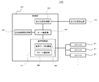
- FIG. 1 is a block diagram illustrating a configuration of the navigation device 100 according to the first embodiment
- FIG. 2 is a schematic perspective view of the navigation device 100 according to the first embodiment
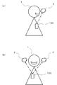
- FIG. 3 is a schematic diagram for explaining the operation of the navigation device 100 according to the first embodiment, in which FIG. 3A is a view of the user 1 viewed from the side (right side), and FIG. ) Is a view of the user 1 as seen from the front.
- the navigation device 100 is based on the current position information acquisition unit (self-position acquisition unit 42) that acquires current position information, the acquired current position information, and the position information of the destination.
- Direction determination unit for example, route search unit 44
- sound generation unit for example, parametric speaker 30
- sound generation unit for example, parametric speaker 30
- sound generation unit so that the user 1 (FIG. 3) can hear the sound from the direction of travel.
- the navigation device 100 is assumed to be a mobile terminal device (a mobile phone, a PDA (Personal Digital Assistant), a small game device, etc.).
- PDA Personal Digital Assistant
- the navigation apparatus 100 includes a control unit 40, a parametric speaker 30, and a self-position detection unit 10.
- the navigation apparatus 100 has a communication function (Internet function, call function, etc.), for example.
- the self-position detection unit 10 detects its current position by, for example, GPS (Global Positioning System).
- GPS Global Positioning System
- the control unit 40 includes a self-position acquisition unit 42, a destination information acquisition unit 43, a route search unit 44, and a voice control unit 41.
- the self-position acquisition unit 42 acquires information indicating the current position detected by the self-position detection unit 10 (hereinafter, current position information) from the self-position detection unit 10.
- the destination information acquisition unit 43 acquires information about the destination (hereinafter referred to as destination information).
- the destination information includes at least information indicating the position of the destination.
- the destination information may contain a variety of other information.
- the destination information acquisition unit 43 As a destination information acquisition method by the destination information acquisition unit 43, for example, the information on the position selected by the operation of the user 1 from the map information downloaded to the navigation device 100 according to the operation of the user 1,
- the destination information may be acquired, but may be acquired by other methods.
- the route search unit 44 is a route for reaching the destination from the current position based on the current position information acquired by the self-position acquisition unit 42 and the position information of the destination acquired by the destination information acquisition unit 43. Search for. Furthermore, the route search unit 44 determines the current direction of travel based on the searched route.
- the audio control unit 41 includes an audio data processing unit 45 and a sound image localization processing unit 46, and controls the parametric speaker 30.
- the voice data processing unit 45 performs a playback process of the voice to be heard by the user 1 during the navigation operation.
- the sound image localization processing unit 46 performs a process of forming (localizing) a sound image at a position in the traveling direction with the user 1 as a reference. That is, the sound image localization processing unit 46 controls the directivity of the sound output from the parametric speaker 30 according to the traveling direction determined by the route search unit 44 so that the user 1 can hear the sound from the traveling direction. To do. As a result, the user 1 can intuitively recognize which direction to proceed from the direction in which the sound is heard.
- a sound image can be formed in a desired region by controlling each oscillation device 31 of the parametric speaker 30 by the sound image localization processing unit 46. That is, the sound image can be localized in a desired region. More specifically, the sound image localization processing unit 46 controls each oscillating device 31 so that the sound image 2 is formed in front of the user 1 when the traveling direction is the front (FIG. 3A). Each oscillation device 31 is controlled so that the sound image 2 is formed on the left side of the user 1 when the direction is left, and each sound image 2 is formed on the right side of the user 1 when the traveling direction is right. The oscillation device 31 is controlled (FIG. 3B).
- the sound image localization processing unit 46 preliminarily outputs the phase value of the ultrasonic wave output from each oscillation device 31 (or is output from each oscillation device 31) for each traveling direction.
- the value of the relative shift amount of the ultrasonic phase) is stored as a table. Then, the sound image localization processing unit 46 extracts a value corresponding to the current traveling direction from the table, and controls the phase of each oscillation device 31 based on the value.
- the sound image localization processing unit 46 controls the directivity of the parametric speaker 30 so that a private sound field is formed for the user 1 so that the sound can be heard only by the user 1.
- a sound image may be formed in an area within 30 cm with the user 1's ear as a reference.
- navigation by the navigation device 100 is performed such that the distance from the navigation device 100 that is a portable terminal device to the ear of the user 1 and the direction of the ear viewed from the navigation device 100 are kept substantially constant. It is assumed that operation will be performed. Specifically, for example, it is assumed that the user 1 performs the navigation operation with the navigation device 100 in the breast pocket. However, even in this case, the distance from the parametric speaker 30 to the ear of the user 1 may differ depending on the size of the body of the user 1 and the design of clothes. Therefore, by registering this distance in advance by the user 1, the position where the sound image is formed by the parametric speaker 30 may be appropriately adjusted, or the voice guidance during the navigation operation may be heard. The directivity of the parametric speaker 30 may be finely adjusted by the user 1 so as to be easy.
- the parametric speaker 30 includes, for example, a plurality of oscillation devices 31 that oscillate ultrasonic waves in an array. These oscillation devices 31 are arranged in a matrix, for example. Further, the parametric speaker 30 includes a signal generation unit 35 that generates an electric signal input to each oscillation device 31.
- the navigation device 100 includes, for example, a rectangular parallelepiped housing 101, and the oscillation device 31 is disposed on an end surface 101 a in the longitudinal direction of the housing 101. Therefore, by placing the navigation device 100 in, for example, a breast pocket with the end surface 101a facing upward, the oscillation device 31 is directed upward, that is, toward the user's face.
- the navigation device 100 may have other forms.
- the navigation device 100 may be a foldable type having first and second casings that are foldably connected to each other, or may be slidably connected to each other. It may be a slide type having
- FIG. 4 is a schematic diagram of the oscillation device 31.
- the oscillation device 31 includes, for example, a sheet-like vibration member 32, a vibrator 33, and a support member 34.
- the vibrator 33 is a piezoelectric vibrator, for example, and is attached to one surface of the vibration member 32.
- the support member 34 supports the edge of the vibration member 32.
- the support member 34 is fixed to, for example, a circuit board (not shown) or the housing 101 of the navigation device 100.
- the signal generation unit 35 and the audio control unit 41 constitute an oscillation circuit that vibrates the transducer 33 by inputting an oscillation signal to the transducer 33 and oscillates a sound wave from the transducer 33 and the vibration member 32.
- the vibrating member 32 vibrates due to vibration generated from the vibrator 33, and oscillates, for example, a sound wave having a frequency of 20 kHz or more.
- the vibrator 33 also oscillates a sound wave having a frequency of, for example, 20 kHz or more by vibrating itself.
- the vibrating member 32 adjusts the basic resonance frequency of the vibrator 33.
- Fundamental resonance frequency of the mechanical oscillator comprises a load weight, dependent on compliance. Since the compliance is the mechanical rigidity of the vibrator, the basic resonance frequency of the vibrator 33 can be controlled by controlling the rigidity of the vibration member 32.
- the thickness of the vibration member 32 is 5 ⁇ m or more 500 ⁇ m or less.
- the vibration member 32 preferably has a longitudinal elastic modulus, which is an index indicating rigidity, of 1 GPa or more and 500 GPa or less.
- a longitudinal elastic modulus which is an index indicating rigidity, of 1 GPa or more and 500 GPa or less.
- the material constituting the vibration member 32 is not particularly limited as long as it is a material having a high elastic modulus with respect to the vibrator 33 which is a brittle material, such as a metal or a resin. Stainless steel or the like is preferable.
- the planar shape of the vibrator 33 is a circle.
- the planar shape of the vibrator 33 is not limited to a circle.
- the entire surface of the vibrator 33 facing the vibration member 32 is fixed to the vibration member 32 with an adhesive. As a result, the entire surface of one side of the vibrator 33 is restrained by the vibration member 32.
- the signal generator 35 generates an electric signal input to the vibrator 33, that is, a modulation signal in the oscillation device 31.
- the transport wave of the modulation signal is, for example, an ultrasonic wave having a frequency of 20 kHz or higher, and specifically, an ultrasonic wave having a frequency of 100 kHz, for example.
- the audio control unit 41 controls the signal generation unit 35 according to the audio signal of the audio to be reproduced.
- FIG. 5 is a cross-sectional view illustrating a thickness direction of the layer structure of the transducer 33.
- the vibrator 33 includes a piezoelectric body 36, an upper surface electrode 37, and a lower surface electrode 38.
- the piezoelectric body 36 is polarized in the thickness direction.
- the material constituting the piezoelectric body 36 may be either an inorganic material or an organic material as long as it has a piezoelectric effect.
- the electro-mechanical conversion efficiency is high material, for example of a zirconate titanate (PZT) or barium titanate (BaTiO 3) preferred.
- the thickness h1 of the piezoelectric body 36 is, for example, not less than 10 ⁇ m and not more than 1 mm. When the thickness h1 is less than 10 ⁇ m, there is a possibility that the vibrator 33 is damaged when the oscillation device 31 is manufactured.
- the thickness h1 is more than 1 mm, the electromechanical conversion efficiency becomes too low, and there is a possibility that a sufficiently large vibration cannot be obtained.
- the reason is that as the thickness of the vibrator 33 increases, the electric field strength in the piezoelectric vibrator decreases in inverse proportion.
- the material which comprises the upper surface electrode 37 and the lower surface electrode 38 is not specifically limited, For example, silver and silver / palladium can be used. Since silver is used as a general-purpose electrode material with low resistance, it has advantages in manufacturing process and cost. Since silver / palladium is a low-resistance material excellent in oxidation resistance, there is an advantage from the viewpoint of reliability.
- the thickness h2 of the upper surface electrode 37 and the lower surface electrode 38 is not particularly limited, but the thickness h2 is preferably 1 ⁇ m or more and 50 ⁇ m or less. When the thickness h2 is less than 1 ⁇ m, it is difficult to uniformly mold the upper surface electrode 37 and the lower surface electrode 38, and as a result, the electromechanical conversion efficiency may be reduced.
- the upper surface electrode 37 and the lower surface electrode 38 become a restraint surface with respect to the piezoelectric material 36, and there exists a possibility that energy conversion efficiency may fall.
- As the upper surface electrode 37 and the lower surface electrode 38 for example, a silver / palladium alloy having a thickness of 8 ⁇ m (weight ratio is, for example, 7: 3) can be used.
- the parametric speaker 30 radiates ultrasonic waves (transport waves) subjected to AM modulation, DSB modulation, SSB modulation, and FM modulation from each of the plurality of oscillation devices 31 into the air, and nonlinearity when the ultrasonic waves propagate into the air.
- An audible sound appears depending on the characteristic.
- Non-linear means that the flow changes from laminar flow to turbulent flow when the Reynolds number indicated by the ratio between the inertial action and the viscous action of the flow increases. Since the sound wave is slightly disturbed in the fluid, the sound wave propagates nonlinearly. In particular, in the ultrasonic frequency band, the nonlinearity of sound waves can be easily observed.
- Parametric speaker 30 has the advantage of high directivity of the sound.
- the current position information is acquired by the self position acquisition unit 42.
- the destination information acquisition unit 43 acquires destination information.
- the route search unit 44 searches for a route based on the current position information and the destination information, and determines the traveling direction to be headed based on the searched route.
- the audio data processing unit 45 controls the parametric speaker 30 to perform a reproduction process of audio to be heard by the user during the navigation operation.
- the audio data to be reproduced may be stored and held in advance by the navigation device 100.
- the voice in this case may be, for example, information indicating the direction of travel (go forward, go right, etc.), or may be, for example, music.
- the voice data may be input to the navigation device 100 from the outside.
- a sound that is downloaded from the outside to the navigation device 100 at any time may be reproduced, or a sound that is currently audible at the destination or a sound from the other party of the call may be reproduced.
- destination information may be received from a terminal device (not shown) of a person already at the destination, and the voice of a call with that person may be reproduced.
- the type of audio to be played back may be arbitrarily selectable by the user 1.
- FIG. 6 is a schematic plan view for explaining the operation of the navigation device 100 according to the first embodiment.
- FIG. 6 shows an operation of the user 1 toward the destination 3.
- the traveling direction changes as the user 1 moves
- the position where the sound image 2 is localized is changed as needed. That is, the user 1 can be guided to the destination by performing such an operation as needed.
- the parametric speaker 30 is controlled so that the user 1 can hear the voice from the traveling direction, the user 1 does not understand the contents of the voice.
- the navigation operation is performed by forming the private sound image 2 by the parametric speaker 30 which is a directional speaker, it is possible to prevent the sound from being heard by the surrounding people.
- the content of the speech must necessarily be information that indicates the direction of travel (go forward, go right, etc.) it can not, to other useful information (advertising, etc.).
- information related to products and services handled at the destination, music (songs), voice that can understand the current situation in the store as the destination, and the like may be reproduced in the traveling direction of the user 1.
- the navigation operation may be started actively by the user, but may be started automatically by the navigation device 100 or may be started by a command from a device external to the navigation device 100.
- the navigation operation can be started by a command from the external device to the navigation device 100 when the user 1 passes a specific area.
- information (advertisement etc.) can be distributed to the user without a sense of incongruity.
- information distribution with realism can be realized by distributing information while the situation around the user 1 is changing at any time, The advertising effect can be enhanced.
- the navigation device 100 is portable as in this embodiment, it is possible to perform a navigation operation when the user is not a pedestrian but a driver such as an automobile.
- FIG. 7 is a block diagram showing a configuration of the navigation device 100 according to the second embodiment
- FIG. 8 is a schematic perspective view of the navigation device 100 according to the second embodiment.
- the navigation operation is performed such that the relative position between the navigation device 100 and the ear of the user 1 is kept substantially constant.
- the second embodiment an example on the assumption that the relative position between the navigation device 100 and the ear of the user 1 can be changed will be described.
- the navigation apparatus 100 includes a plurality of (for example, two) imaging units (cameras) 21 and 22 for imaging the user 1, and relative positions. And a determination unit 47. As illustrated in FIG. 8, the imaging units 21 and 22 are disposed, for example, on the end surface 101a.
- Each imaging unit 21, 22 outputs image data obtained by imaging of the user 1 to the relative position determination unit 47 of the control unit 40.
- the relative position determination unit 47 determines the relative positional relationship between the ear of the user 1 and the parametric speaker 30 of the navigation device 100 by performing analysis (image processing) on the images input from the imaging units 21 and 22. .
- This relative positional relationship includes the distance between the ear of the user 1 and the parametric speaker 30 and the direction of the ear of the user 1 viewed from the parametric speaker 30.
- the imaging units 21 and 22 and the relative position determination unit 47 constitute a positional relationship detection unit that detects the relative positional relationship between the user 1 and the parametric speaker 30.
- the sound image localization processing unit 46 corrects the position where the sound image 2 is formed according to the relative positional relationship determined by the relative position determining unit 47. That is, the parametric speaker 30 is controlled so that the sound image 2 is always formed at a position in the traveling direction with respect to the user 1 regardless of the relative positional relationship between the ear of the user 1 and the parametric speaker 30 of the navigation device 100. .
- the user 1 can hear the sound from the traveling direction. .
- the positional relationship detection part was comprised by the imaging parts 21 and 22 and the relative position determination part 47
- the imaging parts 21 and 22, an ultrasonic sensor (sonar), and a relative position determination unit 47 may be configured relative position detection unit by.
- the direction of the ear of the user 1 viewed from the parametric speaker 30 is determined based on the images obtained by the imaging units 21 and 22, and the ear of the user 1 and the parametric speaker are determined based on the detection result by the ultrasonic sensor.
- the distance to 30 can be determined.
- FIG. 9 is a block diagram showing the configuration of the navigation device 100 according to the third embodiment
- FIG. 10 is a schematic plan view for explaining the configuration of the navigation device 100 according to the third embodiment.
- the navigation device 100 is a mobile terminal device.
- the navigation device 100 is a vehicle-mounted device.
- the sound generation unit is configured by a plurality of speakers 51 that are distributed around the driver's seat in the vehicle, and the voice control unit 41 corresponds to the traveling direction among the plurality of speakers 51.
- the sound is selectively generated from the speaker 51 to be played.
- the voice control unit 41 includes a speaker selection unit 48 instead of including the sound image localization processing unit 46.
- the speaker selection unit 48 selects a speaker 51 that performs audio output for navigation operation among the plurality of speakers 51.
- the speaker 51 is comprised by the electroconductive type electroacoustic transducer, for example.
- Each of the conductive electroacoustic transducers includes a permanent magnet, a voice coil, and a vibrating membrane.
- these speakers 51 include, for example, a speaker 51a disposed in front of a driver seat 5 of an automobile as an example of a vehicle, a speaker 51b disposed behind the driver seat 5, and a driver seat. 5 and the speaker 51d arrange
- the user 1 who is a driver of the car can hear the voice from the direction of travel, so that the user 1 recognizes the direction of travel without knowing the content of the voice. be able to.
- the speaker 51 can be arranged as much as necessary around the user 1, it is possible to easily output sound from 360 ° around the user 1, for example, from the back of the user 1. It becomes.
- FIG. 11 is a schematic plan view for explaining the configuration of the navigation device 100 according to the fourth embodiment.
- the speaker 51 that is not a directional speaker is used when the navigation device 100 is a vehicle-mounted type.
- a sound image is formed at a position in the traveling direction with the user 1 as a reference by a directional speaker (for example, the parametric speaker 30).
- the configuration of the navigation device 100 according to the present embodiment is as shown in FIG.
- a private sound field can be formed around the user 1 who is a driver, a passenger sitting in the rear seat 6 or the passenger seat 7 is prevented from hearing the sound by the navigation operation. be able to. For this reason, for example, when the child 4 is sleeping in the rear seat 6, the sleep of the child 4 can be prevented from being disturbed.
- the oscillation device 31 of the navigation device 100 according to the present embodiment includes a MEMS (Micro Electro Mechanical Systems) actuator 70 illustrated in FIG. 12 instead of the transducer 33 (FIG. 4).
- the navigation device 100 according to the present embodiment is configured similarly to the navigation device 100 according to the first to fourth embodiments.
- the driving method of the MEMS actuator 70 is a piezoelectric method, and the piezoelectric thin film layer 72 is sandwiched between the upper movable electrode layer 74 and the lower movable electrode layer 76.
- the MEMS actuator 70 operates when a signal is input from the signal generation unit 35 to the upper movable electrode layer 74 and the lower movable electrode layer 76.
- an aerosol deposition method is used for manufacturing the MEMS actuator 70, but the method is not limited to this method. However, it is preferable to use the aerosol deposition method because the piezoelectric thin film layer 72, the upper movable electrode layer 74, and the lower movable electrode layer 76 can be formed on curved surfaces.
- the driving method of the MEMS actuator 70 may be an electrostatic method, an electromagnetic method, or a heat conduction method.
- FIG. 13 is a block diagram showing the configuration of the navigation device 100 according to the sixth embodiment
- FIG. 14 is a schematic perspective view of the navigation device 100 according to the sixth embodiment
- FIG. 15 is related to the sixth embodiment.
- 4 is a schematic diagram for explaining the operation of the navigation device 100.
- the position where the sound image is formed is controlled by controlling the phase of the ultrasonic wave output from each oscillation device 31 of the parametric speaker 30 has been described.
- the directivity of the parametric speaker 30 is controlled by changing the output direction of the sound wave from the oscillation device 31 by the actuator 39, and the position where the sound image is formed, that is, the audible sound is demodulated. Control the position.
- the parametric speaker 30 includes, for example, a single (one) oscillation device 31 and a plurality of actuators 39 for changing the orientation of the oscillation device 31. And a support portion 39a to which these actuators 39 are fixed.
- the support portion 39a is fixed directly or indirectly to the housing 101 of the navigation device 100.
- the support part 39a is formed in a flat plate shape, for example.
- the actuator 39 is, for example, a piezoelectric element, and expands and contracts by controlling the applied voltage.
- One end of each actuator 39 is fixed to the support portion 39a, and the other end is fixed to, for example, the support member 34 of the oscillation device 31.
- each actuator 39 is provided to stand vertically from one surface of the support portion 39a.
- the number of actuators 39 can be two or three.
- the degree of freedom in adjusting the orientation of the oscillation device 31 is increased.
- the oscillating device 31 is disposed on the end face 101a, for example.
- FIG. 15 shows the operation when there are two actuators 39 for the sake of simplicity.
- the output direction of the ultrasonic wave from the oscillation device 31 is opposite to the support portion 39a (that is, the vibration member 32 and the support portion of the oscillation device 31). 39a are parallel to each other). Therefore, the sound image 2 is formed in the front direction of the support portion 39a (FIG. 15A).
- the angle of the oscillation device 31 with respect to the support portion 39a is changed, and the output direction of the ultrasonic wave from the oscillation device 31 is changed. (That is, the vibration member 32 can be inclined with respect to the support portion 39a). Therefore, the sound image 2 is formed at a position offset from the front surface of the support portion 39a (FIGS. 15B and 15C).
- the sound image 2 can be formed on the left side or the right side of the user 1 by appropriately extending or contracting each actuator 39.
- the same effect as in the first embodiment can be obtained.
- the parametric speaker 30 since the output position of the sound wave from the oscillation device 31 is changed by the actuator 39 to change the formation position of the sound image 2, the parametric speaker 30 includes a plurality of oscillation devices 31 in an array form. For example, a single oscillation device 31 may be provided.
- the description has been made on the assumption that there is only one destination and the sound can be heard only from one traveling direction at a time.
- there are a plurality of destinations and each destination from the traveling direction corresponding to the ground may be voice can be heard at the same time. That is, the route search unit 44 determines a plurality of traveling directions based on the current position information and the position information of each of the plurality of destinations, and the voice control unit 41 determines a plurality of traveling directions for the user 1.
- the parametric loudspeaker 30 may be controlled so that different sounds can be heard from each of them simultaneously.
- the user 1 can hear the sound from a plurality of directions in the same way as the user 1 can selectively hear the information he / she wants to hear even if different sounds can be heard from various directions in real life. also, it is possible to listen to the information you want to hear themselves selectively.
- the description has been made on the assumption that the traveling direction is any place in the horizontal direction, but the destination is above (for example, going up stairs) or below (for example, stairs). You may go down).
- the description has been made on the assumption that the position of the destination is fixed, but the destination may move.
- the destination information acquisition unit 43 of the navigation device 100 uses the other navigation device. For example, an operation of acquiring 100 position information is performed.
- the two users can intuitively recognize each other's position, so that the users can quickly gather at some point. By performing such operations while talking with each other using the mobile terminal device (navigation device 100), it is possible to gather more smoothly.
- the number of users is not limited to two, and the same applies to three or more users.
- the destination information acquisition unit 43 of the navigation device 100 of one or more other users acquires the position information of the mobile terminal device. You may make it perform operation
- the other one or more users can intuitively recognize the position of the one user, and thus can quickly go to the destination location of the one user, Each user can easily gather. Further, not only when each user holds the navigation device 100 that is a portable terminal device, but also when the navigation device 100 is a vehicle-mounted type and each user moves by car, the position information of each other Can be gathered quickly by acquiring the location information of a single user.
Landscapes
- Engineering & Computer Science (AREA)
- Remote Sensing (AREA)
- Radar, Positioning & Navigation (AREA)
- Automation & Control Theory (AREA)
- Physics & Mathematics (AREA)
- General Physics & Mathematics (AREA)
- Multimedia (AREA)
- General Health & Medical Sciences (AREA)
- Audiology, Speech & Language Pathology (AREA)
- Health & Medical Sciences (AREA)
- Acoustics & Sound (AREA)
- Signal Processing (AREA)
- Circuit For Audible Band Transducer (AREA)
- Navigation (AREA)
Abstract
ナビゲーション装置(100)は、現在位置情報を取得する現在位置情報取得部(自己位置取得部(42))と、取得した現在位置情報と目的地の位置情報とに基づいて進行方向を判定する進行方向判定部(例えば、ルート検索部(44))とを有する。ナビゲーション装置(100)は、更に、音声を発音する発音部(例えば、パラメトリックスピーカ(30))と、ユーザに対し進行方向から音声が聞こえるように発音部を制御する音声制御部(41)とを有する。
Description
本発明は、ナビゲーション装置に関する。
一般的なナビゲーション装置では、表示や音声により進行方向をユーザに案内する(例えば、特許文献1)。
なお、特許文献2には、パラメトリックスピーカを用いて音像を所定位置に定位させる技術が記載されている。
一般的なナビゲーション装置では、音声により進行方向を案内する場合にも、その音声を注意深く聞いてその内容を言語として理解しなければ、ユーザは進行方向を認識することができない。
本発明の目的は、ユーザが音声の内容までは分からなくても進行方向を直感的に認識することが可能なナビゲーション装置を提供することにある。
本発明は、現在位置情報を取得する現在位置情報取得部と、
取得した前記現在位置情報と、目的地の位置情報と、に基づいて、進行方向を判定する進行方向判定部と、
音声を発音する発音部と、
ユーザに対し前記進行方向から音声が聞こえるように前記発音部を制御する音声制御部と、
を有することを特徴とするナビゲーション装置を提供する。
取得した前記現在位置情報と、目的地の位置情報と、に基づいて、進行方向を判定する進行方向判定部と、
音声を発音する発音部と、
ユーザに対し前記進行方向から音声が聞こえるように前記発音部を制御する音声制御部と、
を有することを特徴とするナビゲーション装置を提供する。
本発明によれば、ユーザは、音声の内容までは分からなくても進行方向を直感的に認識することができる。
上述した目的、およびその他の目的、特徴および利点は、以下に述べる好適な実施の形態、およびそれに付随する以下の図面によってさらに明らかになる。
以下、本発明の実施形態について、図面を用いて説明する。なお、すべての図面において、同様の構成要素には同一の符号を付し、適宜に説明を省略する。
〔第1の実施形態〕
図1は第1の実施形態に係るナビゲーション装置100の構成を示すブロック図、図2は第1の実施形態に係るナビゲーション装置100の模式的な斜視図である。図3は第1の実施形態に係るナビゲーション装置100の動作を説明するための模式図であり、このうち図3(a)はユーザ1を側方(右側)から見た図、図3(b)はユーザ1を前方から見た図である。
図1は第1の実施形態に係るナビゲーション装置100の構成を示すブロック図、図2は第1の実施形態に係るナビゲーション装置100の模式的な斜視図である。図3は第1の実施形態に係るナビゲーション装置100の動作を説明するための模式図であり、このうち図3(a)はユーザ1を側方(右側)から見た図、図3(b)はユーザ1を前方から見た図である。
本実施形態に係るナビゲーション装置100は、現在位置情報を取得する現在位置情報取得部(自己位置取得部42)と、取得した現在位置情報と、目的地の位置情報と、に基づいて、進行方向を判定する進行方向判定部(例えば、ルート検索部44)と、音声を発音する発音部(例えば、パラメトリックスピーカ30)と、ユーザ1(図3)に対し進行方向から音声が聞こえるように発音部を制御する音声制御部41と、を有する。なお、本実施形態では、ナビゲーション装置100が携帯端末装置(携帯電話機、PDA(Personal Digital Assistant)、小型ゲーム機器など)であるものとする。また、本実施形態では、ユーザは歩行者としてナビゲーション装置100を携帯する例を説明する。以下、詳細に説明する。
図1に示すように、ナビゲーション装置100は、制御部40と、パラメトリックスピーカ30と、自己位置検出部10と、を有している。なお、ナビゲーション装置100は、例えば、通信機能(インターネット機能、通話機能等)を有していることが好ましい。
自己位置検出部10は、例えば、GPS(Global Positioning System)などにより自己の現在位置を検出する。
制御部40は、自己位置取得部42と、目的地情報取得部43と、ルート検索部44と、音声制御部41と、を有している。
自己位置取得部42は、自己位置検出部10により検出された現在位置を示す情報(以下、現在位置情報)を自己位置検出部10から取得する。
目的地情報取得部43は、目的地に関する情報(以下、目的地情報)を取得する。目的地情報には、少なくとも、目的地の位置を示す情報が含まれる。ただし、目的地情報には、その他の様々な情報が含まれていても良い。
目的地情報取得部43による目的地情報の取得方法としては、例えば、ユーザ1の操作に応じてナビゲーション装置100にダウンロードした地図情報の中から、ユーザ1の操作により選択された位置の情報を、目的地情報として取得することが挙げられるが、その他の方法により取得しても良い。
ルート検索部44は、自己位置取得部42が取得した現在位置情報と、目的地情報取得部43が取得した目的地の位置情報と、に基づいて、現在位置から目的地へ到達するためのルートを検索する。更に、ルート検索部44は、検索したルートに基づき、現在向かうべき進行方向を判別する。
音声制御部41は、音声データ処理部45と、音像定位処理部46と、を有し、パラメトリックスピーカ30の制御を行う。
音声データ処理部45は、ナビゲーション動作の際にユーザ1に聞かせる音声の再生処理を行う。
音像定位処理部46は、ユーザ1を基準として進行方向の位置に、音像を形成させる(定位させる)処理を行う。すなわち、音像定位処理部46は、ルート検索部44により判別された進行方向に応じて、パラメトリックスピーカ30から出力される音声の指向性を制御し、ユーザ1に対し進行方向から音声が聞こえるようにする。これにより、ユーザ1は、音声が聞こえてくる方向から、どの方向に進むべきかを直感的に認識することができるようになっている。
音像定位処理部46によって、パラメトリックスピーカ30の各発振装置31を制御することにより、音像を所望の領域に形成することができる。すなわち、音像を所望の領域に定位させることができる。
より具体的には、音像定位処理部46は、進行方向が前の場合にはユーザ1の前方に音像2が形成されるように各発振装置31を制御し(図3(a))、進行方向が左の場合にはユーザ1の左側に音像2が形成されるように各発振装置31を制御し、進行方向が右の場合にはユーザ1の右側に音像2が形成されるように各発振装置31を制御する(図3(b))。
このような動作を実現するために、例えば、音像定位処理部46は、予め、進行方向毎に、各発振装置31から出力される超音波の位相の値(或いは、各発振装置31から出力される超音波の位相の相対的なずれ量の値)をテーブルとして記憶している。そして、音像定位処理部46は、そのテーブルの中から、現在向かうべき進行方向と対応する値を抽出し、その値に基づいて各発振装置31の位相を制御する。
また、音像定位処理部46は、ユーザ1に対してプライベートな音場が形成されるように、パラメトリックスピーカ30の指向性を制御し、音声がユーザ1に対してのみ聞こえるようにする。具体的には、例えば、音像をユーザ1の耳を基準として30cm以内の領域に形成させることが挙げられる。
本実施形態では、携帯端末装置であるナビゲーション装置100からユーザ1の耳までの距離と、ナビゲーション装置100から見た耳の方向と、がほぼ一定に保たれるようにして、ナビゲーション装置100によるナビゲーション動作を行うことを前提としている。具体的には、例えば、ユーザ1がナビゲーション装置100を胸ポケットに入れた状態でナビゲーション動作を行うことを前提としている。ただし、この場合にも、ユーザ1の体の大きさや服のデザイン等に応じてパラメトリックスピーカ30からユーザ1の耳までの距離等が異なる場合がある。このため、予め、この距離をユーザ1が登録することにより、パラメトリックスピーカ30により音像が形成される位置が適切に調節されるようにしても良いし、或いは、ナビゲーション動作の際の音声案内を聞き取りやすくなるようにパラメトリックスピーカ30の指向性をユーザ1が微調整できるようにしても良い。
パラメトリックスピーカ30は、例えば、それぞれ超音波を発振する複数の発振装置31をアレイ状に備えて構成されている。これら発振装置31は、例えばマトリクス状に配置されている。更に、パラメトリックスピーカ30は、各発振装置31に入力する電気信号を生成する信号生成部35を有する。
図2に示すように、ナビゲーション装置100は、例えば、直方体形状の筐体101を有し、筐体101の長手方向における端面101aに発振装置31が配置されている。このため、端面101aが上向きとなるようにして、ナビゲーション装置100を例えば胸ポケットに入れることにより、発振装置31が上方、すなわちユーザの顔の方に向くようになっている。
なお、図2では、ナビゲーション装置100が単純な直方体形状である例を示しているが、ナビゲーション装置100は、その他の形態のものであっても良い。例えば、ナビゲーション装置100は、相互に折り畳み可能に連結された第1及び第2の筐体を有する折り畳み型であっても良いし、相互にスライド可能に連結された第1及び第2の筐体を有するスライド型であっても良い。
図4は発振装置31の模式図である。
発振装置31は、例えば、シート状の振動部材32と、振動子33と、支持部材34と、を備えている。振動子33は例えば圧電振動子であり、振動部材32の一方の面に取り付けられている。支持部材34は、振動部材32の縁を支持している。また、支持部材34は、例えば、ナビゲーション装置100の回路基板(図示略)或いは筐体101に固定されている。
信号生成部35及び音声制御部41は、振動子33に発振信号を入力することによって振動子33を振動させて、振動子33及び振動部材32より音波を発振させる発振回路を構成している。
信号生成部35及び音声制御部41は、振動子33に発振信号を入力することによって振動子33を振動させて、振動子33及び振動部材32より音波を発振させる発振回路を構成している。
振動部材32は、振動子33から発生した振動によって振動し、例えば周波数が20kHz以上の音波を発振する。なお、振動子33も、自身が振動することによって、例えば周波数が20kHz以上の音波を発振する。また振動部材32は、振動子33の基本共振周波数を調整する。機械振動子の基本共振周波数は、負荷重量と、コンプライアンスに依存する。コンプライアンスは振動子の機械剛性であるため、振動部材32の剛性を制御することで、振動子33の基本共振周波数を制御できる。なお、振動部材32の厚みは5μm以上500μm以下であることが好ましい。また、振動部材32は、剛性を示す指標である縦弾性係数が1Gpa以上500GPa以下であることが好ましい。振動部材32の剛性が低すぎる場合や、高すぎる場合は、機械振動子として特性や信頼性を損なう可能性が出てくる。なお、振動部材32を構成する材料は、金属や樹脂など、脆性材料である振動子33に対して高い弾性率を持つ材料であれば特に限定されないが、加工性やコストの観点からリン青銅やステンレスなどが好ましい。
本実施形態において、振動子33の平面形状は円形である。ただし振動子33の平面形状は円形に限定されない。振動子33は、振動部材32に対向する面の全面が接着剤によって振動部材32に固定されている。これにより、振動子33の片面の全面が振動部材32によって拘束される。
信号生成部35は、振動子33に入力する電気信号、すなわち発振装置31における変調信号を生成する。変調信号の輸送波は、例えば、周波数が20kHz以上の超音波であり、具体的には、例えば100kHzの超音波である。音声制御部41は、再生すべき音声の音声信号に応じて、信号生成部35を制御する。
図5は、振動子33の厚さ方向の層構造を示す断面図である。振動子33は、圧電体36、上面電極37及び下面電極38を有している。
圧電体36は厚さ方向に分極している。圧電体36を構成する材料は、圧電効果を有する材料であれば、無機材料及び有機材料のいずれであってもよい。ただし、電気機械変換効率が高い材料、例えばジルコン酸チタン酸塩(PZT)やチタン酸バリウム(BaTiO3)であるのが好ましい。圧電体36の厚さh1は、例えば10μm以上1mm以下である。厚さh1が10μm未満の場合、発振装置31の製造時に振動子33が破損する可能性が生じる。また厚さh1が1mm超の場合、電気機械変換効率が低くなりすぎてしまい、十分な大きさの振動を得られない可能性がある。その理由は、振動子33の厚さが厚くなると、圧電振動子内における電界強度は反比例して小さくなるためである。
上面電極37及び下面電極38を構成する材料は特に限定されないが、例えば、銀や銀/パラジウムを使用することができる。銀は低抵抗で汎用的な電極材料として使用されているため、製造プロセスやコストなどに利点がある。銀/パラジウムは耐酸化に優れた低抵抗材料であるため、信頼性の観点から利点がある。また、上面電極37及び下面電極38の厚さh2は特に限定されないが、その厚さh2が1μm以上50μm以下であるのが好ましい。厚さh2が1μm未満では、上面電極37及び下面電極38を均一に成形することが難しくなり、その結果、電気機械変換効率が低下する可能性がある。また、上面電極37及び下面電極38の膜厚が100μmを超える場合は、上面電極37及び下面電極38が圧電体36に対して拘束面となり、エネルギー変換効率を低下させてしまう可能性が生じる。
振動子33は、外径=φ18mm、内径=φ12mm、厚み=100μmとすることができる。また上面電極37及び下面電極38としては、例えば厚み8μmの銀/パラジウム合金(重量比は例えば7:3)を用いることができる。また振動部材32は、外径=φ20mm、厚み=50μm(0.3mm)のリン青銅を用いることができる。支持部材34は発振装置31のケースとして機能するものであり、例えば、外径=φ22mm、内径=φ20mmの筒状(例えば円筒状)に形成されている。
パラメトリックスピーカ30は、複数の発振装置31それぞれからAM変調やDSB変調、SSB変調、FM変調をかけた超音波(輸送波)を空気中に放射し、超音波が空気中に伝播する際の非線形特性により、可聴音を出現させるものである。ここでの非線形とは、流れの慣性作用と粘性作用の比で示されるレイノルズ数が大きくなると、層流から乱流に推移することを示す。音波は流体内で微少にじょう乱しているため、音波は非線形で伝播している。特に超音波周波数帯では音波の非線形性が容易に観察できる。そして超音波を空気中に放射した場合、音波の非線形性に伴う高調波が顕著に発生する。また音波は、空気中において分子密度に濃淡が生じる疎密状態である。そして空気分子が圧縮するよりも復元するのに時間を要した場合、圧縮後に復元できない空気が、連続的に伝播する空気分子と衝突し、衝撃波が生じる。この衝撃波により可聴音が発生する、つまり可聴音が再生(復調)される。パラメトリックスピーカ30は、音の指向性が高いという利点がある。
次に、一連の動作を説明する。
先ず、自己位置取得部42にて現在位置情報を取得する。また、目的地情報取得部43にて目的地情報を取得する。
次に、ルート検索部44にて、現在位置情報と目的地情報とに基づいてルートを検索し、検索したルートに基づき、現在向かうべき進行方向を判別する。
次に、音声データ処理部45は、パラメトリックスピーカ30を制御することにより、ナビゲーション動作の際にユーザに聞かせる音声の再生処理を行う。
ここで、再生する音声のデータ(音声データ)は、ナビゲーション装置100が予め記憶保持していても良い。この場合の音声は、例えば、進行方向を意味する情報(前に進んで下さい、右に進んで下さい、など)であることが挙げられるが、或いは、例えば音楽などであっても良い。
また、音声データは、外部からナビゲーション装置100に入力されるのでもよい。例えば、外部からナビゲーション装置100に随時にダウンロード(例えば、Webからダウンロード)される音声を再生するのでも良いし、目的地において現在聞こえる音声や、通話の相手方からの音声を再生するのでも良い。より具体的には、例えば、既に目的地にいる人の端末装置(図示略)から、目的地情報を受信するとともに、その人との通話の音声を再生するのでも良い。
また、再生する音声の種類は、ユーザ1が任意に選択できるようになっていても良い。
また、音声データは、外部からナビゲーション装置100に入力されるのでもよい。例えば、外部からナビゲーション装置100に随時にダウンロード(例えば、Webからダウンロード)される音声を再生するのでも良いし、目的地において現在聞こえる音声や、通話の相手方からの音声を再生するのでも良い。より具体的には、例えば、既に目的地にいる人の端末装置(図示略)から、目的地情報を受信するとともに、その人との通話の音声を再生するのでも良い。
また、再生する音声の種類は、ユーザ1が任意に選択できるようになっていても良い。
また、音声データ処理部45による再生処理と並行して、音像定位処理部46により、パラメトリックスピーカ30から出力される音声の指向性を制御し、ユーザ1に対し進行方向から音声が聞こえるようにする。
図6は第1の実施形態に係るナビゲーション装置100の動作を説明するための模式的な平面図である。図6は、ユーザ1が目的地3に向かう動作を示す。
ユーザ1の移動に伴い、進行方向が変化すると、音像2を定位する位置を随時変更する。すなわち、このような動作を随時行うことにより、ユーザ1を目的地に導くことができる。
図6は第1の実施形態に係るナビゲーション装置100の動作を説明するための模式的な平面図である。図6は、ユーザ1が目的地3に向かう動作を示す。
ユーザ1の移動に伴い、進行方向が変化すると、音像2を定位する位置を随時変更する。すなわち、このような動作を随時行うことにより、ユーザ1を目的地に導くことができる。
以上のような第1の実施形態によれば、ユーザ1に対し進行方向から音声が聞こえるようにパラメトリックスピーカ30の制御を行うので、ユーザ1は、音声の内容までは分からなくても(聞き取れなくても)、音声が聞こえる方向から直感的に進行方向を認識することができる。つまり、直感的なナビゲーションが可能である。
また、指向性スピーカであるパラメトリックスピーカ30によって、プライベートな音像2を形成することで、ナビゲーション動作を行うので、音声が周囲の人に聞かれないようにすることができる。
また、進行方向に音像2を定位することによって進行方向をユーザ1に認識させるため、音声の内容は必ずしも進行方向を意味する情報(前に進んで下さい、右に進んで下さいなど)である必要はなく、それ以外の有益な情報(広告等)にすることができる。例えば、目的地で扱う商品やサービスに関する情報、音楽(歌)、目的地である店内の現在の状況が分かるような音声等をユーザ1の進行方向において再生させても良い。
また、ナビゲーション動作は、ユーザが能動的に開始しても良いが、ナビゲーション装置100が自動的に開始したり、或いは、ナビゲーション装置100の外部の装置からの指令により開始したりしても良い。例えば、ユーザ1が街を歩いているときに、特定の領域を通過した場合に、外部の装置からナビゲーション装置100に対する指令によりナビゲーション動作が開始するようにすることができる。これらの場合にも、ユーザに対して情報(広告等)を違和感なく配信することができる。また、ナビゲーション動作により導かれてユーザ1が移動する結果として、ユーザ1の周囲の状況が随時変化している最中に、情報の配信を行うことにより、臨場感を伴う情報配信を実現でき、広告効果を高めることができる。
なお、本実施形態のようにナビゲーション装置100が携帯型の場合にも、ユーザが歩行者ではなく自動車等の運転者の場合におけるナビゲーション動作を行うことも可能である。
〔第2の実施形態〕
図7は第2の実施形態に係るナビゲーション装置100の構成を示すブロック図、図8は第2の実施形態に係るナビゲーション装置100の模式的な斜視図である。
上記の第1の実施形態では、ナビゲーション装置100とユーザ1の耳との相対位置がほぼ一定に保たれるようにしてナビゲーション動作を行うことを前提とした。これに対し、第2の実施形態では、ナビゲーション装置100とユーザ1の耳との相対位置が変化し得ることを前提とした例を説明する。
図7は第2の実施形態に係るナビゲーション装置100の構成を示すブロック図、図8は第2の実施形態に係るナビゲーション装置100の模式的な斜視図である。
上記の第1の実施形態では、ナビゲーション装置100とユーザ1の耳との相対位置がほぼ一定に保たれるようにしてナビゲーション動作を行うことを前提とした。これに対し、第2の実施形態では、ナビゲーション装置100とユーザ1の耳との相対位置が変化し得ることを前提とした例を説明する。
図7に示すように、本実施形態に係るナビゲーション装置100は、図1の構成に加えて、それぞれユーザ1を撮像する複数(例えば2つ)の撮像部(カメラ)21、22と、相対位置判定部47と、を有している。図8に示すように、撮像部21、22は、例えば、端面101aに配置されている。
各撮像部21、22は、ユーザ1の撮像により得られた画像データをそれぞれ制御部40の相対位置判定部47へ出力する。
相対位置判定部47では、撮像部21、22から入力された画像に対して解析(画像処理)を行うことによって、ユーザ1の耳とナビゲーション装置100のパラメトリックスピーカ30との相対位置関係を判定する。この相対位置関係には、ユーザ1の耳とパラメトリックスピーカ30との距離と、パラメトリックスピーカ30から見たユーザ1の耳の方向と、が含まれる。
なお、これら撮像部21、22及び相対位置判定部47により、ユーザ1とパラメトリックスピーカ30との相対位置関係を検出する位置関係検出部が構成されている。
相対位置判定部47では、撮像部21、22から入力された画像に対して解析(画像処理)を行うことによって、ユーザ1の耳とナビゲーション装置100のパラメトリックスピーカ30との相対位置関係を判定する。この相対位置関係には、ユーザ1の耳とパラメトリックスピーカ30との距離と、パラメトリックスピーカ30から見たユーザ1の耳の方向と、が含まれる。
なお、これら撮像部21、22及び相対位置判定部47により、ユーザ1とパラメトリックスピーカ30との相対位置関係を検出する位置関係検出部が構成されている。
音像定位処理部46は、相対位置判定部47により判定された相対位置関係に応じて、音像2を形成する位置を補正する。すなわち、ユーザ1の耳とナビゲーション装置100のパラメトリックスピーカ30との相対位置関係にかかわらず、常に、ユーザ1を基準として進行方向の位置に音像2が形成されるように、パラメトリックスピーカ30を制御する。
以上のような第2の実施形態によれば、ユーザ1の耳とナビゲーション装置100のパラメトリックスピーカ30との相対位置関係にかかわらず、ユーザ1に対し進行方向から音声が聞こえるようにすることができる。
なお、第2の実施形態では、撮像部21、22及び相対位置判定部47により位置関係検出部が構成されている例を説明したが、撮像部21、22と、超音波センサ(ソナー)と、相対位置判定部47と、により相対位置検出部を構成しても良い。この場合、撮像部21、22により得られた画像に基づいて、パラメトリックスピーカ30から見たユーザ1の耳の方向を判定し、超音波センサによる検出結果に基づいて、ユーザ1の耳とパラメトリックスピーカ30との距離を判定することができる。
〔第3の実施形態〕
図9は第3の実施形態に係るナビゲーション装置100の構成を示すブロック図、図10は第3の実施形態に係るナビゲーション装置100の構成を説明するための模式的な平面図である。
図9は第3の実施形態に係るナビゲーション装置100の構成を示すブロック図、図10は第3の実施形態に係るナビゲーション装置100の構成を説明するための模式的な平面図である。
上記の各実施形態では、ナビゲーション装置100が携帯端末装置である例を説明したが、本実施形態では、ナビゲーション装置100が車載型である例を説明する。
第3の実施形態では、発音部は、車両内において運転席の周囲に分散して配置された複数のスピーカ51により構成され、音声制御部41は、複数のスピーカ51のうち、進行方向と対応するスピーカ51から選択的に音声を発音させる。すなわち、音声制御部41は、音像定位処理部46を備えていない代わりに、スピーカ選択部48を有している。このスピーカ選択部48は、複数のスピーカ51のうち、ナビゲーション動作のための音声出力を行うスピーカ51を選択する。
上記の各実施形態では、発音部が指向性スピーカ(例えばパラメトリックスピーカ30)である例を説明した。これに対し、本実施形態では、スピーカ51は、例えば、導電型電気音響変換器により構成されている。この導電型電気音響変換器は、それぞれ、永久磁石とボイスコイルと振動膜とを有する。
図10に示すように、これらスピーカ51には、例えば、車両の一例としての自動車の運転席5の前方に配置されるスピーカ51aと、運転席5の後方に配置されるスピーカ51bと、運転席5の左側に配置されるスピーカ51cと、運転席5の右側に配置されるスピーカ51dと、が含まれる。
図10に示すように、これらスピーカ51には、例えば、車両の一例としての自動車の運転席5の前方に配置されるスピーカ51aと、運転席5の後方に配置されるスピーカ51bと、運転席5の左側に配置されるスピーカ51cと、運転席5の右側に配置されるスピーカ51dと、が含まれる。
本実施形態の場合、進行方向が前の場合、スピーカ51a~51dのうち、スピーカ51aから選択的に音声を出力させる。同様に、進行方向が左の場合、スピーカ51cから選択的に音声を出力させ、進行方向が右の場合、スピーカ51dから選択的に音声を出力させる。また、進行方向が後ろの場合(前に進み過ぎたことをユーザ1に報知する場合など)には、スピーカ51bから選択的に音声を出力させる。
このような第3の実施形態によっても、自動車の運転者であるユーザ1に対し進行方向から音声が聞こえるようにできるため、ユーザ1は、音声の内容までは分からなくても進行方向を認識することができる。
また、ユーザ1の周囲に必要なだけスピーカ51を配置することができるため、ユーザ1の周囲360°からの音声出力を容易に行うことができ、例えば、ユーザ1の後方からの音声出力も可能となる。
また、ユーザ1の周囲に必要なだけスピーカ51を配置することができるため、ユーザ1の周囲360°からの音声出力を容易に行うことができ、例えば、ユーザ1の後方からの音声出力も可能となる。
〔第4の実施形態〕
図11は第4の実施形態に係るナビゲーション装置100の構成を説明するための模式的な平面図である。
図11は第4の実施形態に係るナビゲーション装置100の構成を説明するための模式的な平面図である。
上記の第3の実施形態では、ナビゲーション装置100が車載型である場合に、指向性スピーカではないスピーカ51を用いる例を説明した。これに対し、第4の実施形態では、ナビゲーション装置100が車載型である場合にも、指向性スピーカ(例えばパラメトリックスピーカ30)によりユーザ1を基準とした進行方向の位置に音像を形成する。なお、本実施形態に係るナビゲーション装置100の構成は、図1に示す通りである。
本実施形態では、運転者であるユーザ1の周囲にプライベートな音場を形成することができるので、後部座席6や助手席7に座っている乗員にはナビゲーション動作による音声が聞こえないようにすることができる。このため、例えば、後部座席6で子供4が寝ている場合などに、子供4の安眠を妨げないようにすることができる。
〔第5の実施形態〕
本実施形態に係るナビゲーション装置100の発振装置31は、振動子33(図4)の代わりに、図12に示したMEMS(Micro Electro Mechanical Systems)アクチュエータ70を有している。その他の点では、本実施形態に係るナビゲーション装置100は、第1乃至第4の実施形態に係るナビゲーション装置100と同様に構成されている。
本実施形態に係るナビゲーション装置100の発振装置31は、振動子33(図4)の代わりに、図12に示したMEMS(Micro Electro Mechanical Systems)アクチュエータ70を有している。その他の点では、本実施形態に係るナビゲーション装置100は、第1乃至第4の実施形態に係るナビゲーション装置100と同様に構成されている。
図12に示す例において、MEMSアクチュエータ70の駆動方式は圧電方式であり、圧電薄膜層72を上部可動電極層74及び下部可動電極層76ではさんだ構造を有している。MEMSアクチュエータ70は、信号生成部35から上部可動電極層74及び下部可動電極層76に信号が入力されることにより動作する。MEMSアクチュエータ70の製造には、例えばエアロゾルデポジション法が用いられるが、この方法に限定されない。ただしエアロゾルデポジション法を用いた場合、圧電薄膜層72、上部可動電極層74及び下部可動電極層76をそれぞれ曲面上にも成膜できるため好ましい。なおMEMSアクチュエータ70の駆動方式は、静電方式、電磁方式、又は熱伝導方式であってもよい。
〔第6の実施形態〕
図13は第6の実施形態に係るナビゲーション装置100の構成を示すブロック図、図14は第6の実施形態に係るナビゲーション装置100の模式的な斜視図、図15は第6の実施形態に係るナビゲーション装置100の動作を説明するための模式図である。
図13は第6の実施形態に係るナビゲーション装置100の構成を示すブロック図、図14は第6の実施形態に係るナビゲーション装置100の模式的な斜視図、図15は第6の実施形態に係るナビゲーション装置100の動作を説明するための模式図である。
上記の第1の実施形態では、パラメトリックスピーカ30の各発振装置31から出力される超音波の位相を制御することによって、音像が形成される位置を制御する例を説明した。
これに対し、本実施形態では、発振装置31からの音波の出力方向をアクチュエータ39によって変化させることにより、パラメトリックスピーカ30の指向性を制御し、音像が形成される位置、すなわち可聴音が復調される位置を制御する。
これに対し、本実施形態では、発振装置31からの音波の出力方向をアクチュエータ39によって変化させることにより、パラメトリックスピーカ30の指向性を制御し、音像が形成される位置、すなわち可聴音が復調される位置を制御する。
図15に示すように、本実施形態の場合、パラメトリックスピーカ30は、例えば、単一の(1個の)発振装置31と、この発振装置31の向きを変化させるための複数のアクチュエータ39と、これらアクチュエータ39が固定された支持部39aと、を有している。
支持部39aは、ナビゲーション装置100の筐体101に直接的又は間接的に固定されている。支持部39aは、例えば、平板状に形成されている。
アクチュエータ39は、例えば、圧電素子であり、印加する電圧を制御することによって、伸縮する。各アクチュエータ39の一端は、それぞれ支持部39aに固定され、他端は発振装置31の例えば支持部材34にそれぞれ固定されている。例えば、各アクチュエータ39は、支持部39aの一方の面上からそれぞれ垂直に起立するように設けられている。
アクチュエータ39の数は2つ又は3つとすることができる。3つのアクチュエータ39を設ける場合の方が、発振装置31の向きの調節の自由度が高まる。このため、本実施形態では、図13に示すように、3つのアクチュエータ39を有していることが好ましい。これらアクチュエータ39の伸縮動作は、制御部40のアクチュエータ制御部49が行う。
なお、図14に示すように、本実施形態でも、発振装置31は、例えば端面101aに配置されている。
図15では、説明を簡単にするため、アクチュエータ39が2つの場合の動作を示す。
各アクチュエータ39の長さが等しいとき、発振装置31からの超音波の出力方向は、支持部39aに対して反対方向となるようになっている(つまり、発振装置31の振動部材32と支持部39aとが互いに平行となるようになっている)。よって、音像2が支持部39aの正面方向に形成される(図15(a))。
また、何れか一方のアクチュエータ39を縮める(又は何れか一方のアクチュエータ39を伸ばす)ことにより、支持部39aに対する発振装置31の角度を変更し、発振装置31からの超音波の出力方向を変化させることができる(つまり支持部39aに対して振動部材32を傾斜させた状態とすることができる)。よって、支持部39aの正面からオフセットした位置に音像2が形成される(図15(b)、図15(c))。
従って、本実施形態では、各アクチュエータ39を適宜に伸縮させることにより、音像2をユーザ1の左側に形成したり、右側に形成したりすることができる。
第6の実施形態によれば、第1の実施形態と同様の効果が得られる。
また、第6の実施形態の場合、発振装置31からの音波の出力方向をアクチュエータ39により変化させることによって、音像2の形成位置を変化させるので、パラメトリックスピーカ30は複数の発振装置31をアレイ状に有する必要が無く、例えば、単一の発振装置31を有するだけでも構わない。
また、第6の実施形態の場合、発振装置31からの音波の出力方向をアクチュエータ39により変化させることによって、音像2の形成位置を変化させるので、パラメトリックスピーカ30は複数の発振装置31をアレイ状に有する必要が無く、例えば、単一の発振装置31を有するだけでも構わない。
上記の各実施形態では、目的地が1つであり、一度に1つの進行方向からのみ音声が聞こえるようにすることを前提とした説明を行ったが、目的地が複数存在し、それぞれの目的地と対応する進行方向から同時に音声が聞こえるようにしても良い。すなわち、ルート検索部44は、現在位置情報と、複数の目的地のそれぞれの位置情報と、に基づいて、複数の進行方向を判定し、音声制御部41は、ユーザ1に対し複数の進行方向のそれぞれから互いに異なる音声が一度に聞こえるように、パラメトリックスピーカ30を制御しても良い。この場合、ユーザ1は、実生活において様々な方向からそれぞれ異なる音声が聞こえてきても自身が聞きたい情報を選択的に聞くことができるのと同様に、複数の方向からそれぞれ音声が聞こえてきても、自身が聞きたい情報を選択的に聞くことができる。
また、上記の各実施形態では、進行方向が水平方向の何れかの場所であることを前提とした説明を行ったが、目的地が上(例えば、階段を上るなど)や下(例えば、階段を下りるなど)であっても良い。
また、上記の各実施形態では、目的地の位置が固定であることを前提とした説明を行ったが、目的地が移動しても良い。例えば、2人のユーザがそれぞれ第1の実施形態で説明したような携帯端末装置であるナビゲーション装置100を持って移動しながら、それらナビゲーション装置100の目的地情報取得部43が、他方のナビゲーション装置100の位置情報を取得する動作を行うことが挙げられる。このような動作を行う結果として、2人のユーザが互いの位置を直感的に認識できるので、ユーザどうしが速やかにどこかの地点に集合することができる。このような動作を、お互いに携帯端末装置(ナビゲーション装置100)を用いて通話しながら行うことにより、よりスムーズに集合することができる。なお、ユーザは2人に限らず、3人以上であっても同様である。
また、ある1人のユーザが携帯端末装置を持って移動しながら、この携帯端末装置の位置情報を、他の1人或いは複数人のユーザのナビゲーション装置100の目的地情報取得部43が取得する動作を行うようにしても良い。この場合、当該他の1人或いは複数人のユーザは、直感的に、当該1人のユーザの位置を認識できるので、当該1人のユーザの移動先の地点へと速やかに向かうことができ、各ユーザが容易に集合することができる。
また、各ユーザが携帯端末装置であるナビゲーション装置100を保持している場合に限らず、ナビゲーション装置100が車載型であり、各ユーザが車で移動する場合についても、同様に、互いの位置情報を取得したり、ある1人のユーザの位置情報を取得したりすることによって、速やかに集合することができる。
この出願は、2011年1月26日に出願された日本出願特願2011-013972号を基礎とする優先権を主張し、その開示の全てをここに取り込む。
Claims (9)
- 現在位置情報を取得する現在位置情報取得部と、
取得した前記現在位置情報と、目的地の位置情報と、に基づいて、進行方向を判定する進行方向判定部と、
音声を発音する発音部と、
ユーザに対し前記進行方向から音声が聞こえるように前記発音部を制御する音声制御部と、
を有することを特徴とするナビゲーション装置。 - 前記発音部は指向性スピーカにより構成され、
前記音声制御部は、前記ユーザを基準として前記進行方向の位置に、前記発音部によって前記音声の音像を形成させることを特徴とする請求項1に記載のナビゲーション装置。 - 前記指向性スピーカはパラメトリックスピーカであることを特徴とする請求項2に記載のナビゲーション装置。
- 前記ユーザと前記発音部との相対位置関係を検出する位置関係検出部を更に有し、
前記音声制御部は、前記位置関係検出部により検出された相対位置関係に応じて前記発音部を制御することを特徴とする請求項1乃至3の何れか一項に記載のナビゲーション装置。 - 前記音声制御部は、前記音像を前記ユーザの耳を基準として30cm以内の領域に形成させることを特徴とする請求項2又は3に記載のナビゲーション装置。
- 当該ナビゲーション装置は、携帯端末装置であることを特徴とする請求項1乃至5の何れか一項に記載のナビゲーション装置。
- 前記発音部は、車両内において運転席の周囲に分散して配置される複数のスピーカにより構成され、
前記音声制御部は、前記複数のスピーカのうち、前記進行方向と対応するスピーカから選択的に前記音声を発音させることを特徴とする請求項1に記載のナビゲーション装置。 - 前記音声制御部は、前記進行方向を意味する情報以外の情報を前記ユーザに伝達するための前記音声を前記発音部に発音させることを特徴とする請求項1乃至7の何れか一項に記載のナビゲーション装置。
- 前記進行方向判定部は、前記現在位置情報と、複数の目的地のそれぞれの位置情報と、に基づいて、複数の進行方向を判定し、
前記音声制御部は、前記ユーザに対し前記複数の進行方向のそれぞれから互いに異なる音声が一度に聞こえるように前記発音部を制御することを特徴とする請求項1乃至8の何れか一項に記載のナビゲーション装置。
Priority Applications (3)
| Application Number | Priority Date | Filing Date | Title |
|---|---|---|---|
| EP11856707.2A EP2670164A4 (en) | 2011-01-26 | 2011-12-01 | NAVIGATION DEVICE |
| US13/979,702 US9528833B2 (en) | 2011-01-26 | 2011-12-01 | Navigation apparatus |
| CN2011800660966A CN103329569A (zh) | 2011-01-26 | 2011-12-01 | 导航设备 |
Applications Claiming Priority (2)
| Application Number | Priority Date | Filing Date | Title |
|---|---|---|---|
| JP2011-013972 | 2011-01-26 | ||
| JP2011013972A JP5776962B2 (ja) | 2011-01-26 | 2011-01-26 | ナビゲーション装置 |
Publications (1)
| Publication Number | Publication Date |
|---|---|
| WO2012101713A1 true WO2012101713A1 (ja) | 2012-08-02 |
Family
ID=46580326
Family Applications (1)
| Application Number | Title | Priority Date | Filing Date |
|---|---|---|---|
| PCT/JP2011/006731 WO2012101713A1 (ja) | 2011-01-26 | 2011-12-01 | ナビゲーション装置 |
Country Status (5)
| Country | Link |
|---|---|
| US (1) | US9528833B2 (ja) |
| EP (1) | EP2670164A4 (ja) |
| JP (1) | JP5776962B2 (ja) |
| CN (1) | CN103329569A (ja) |
| WO (1) | WO2012101713A1 (ja) |
Families Citing this family (42)
| Publication number | Priority date | Publication date | Assignee | Title |
|---|---|---|---|---|
| US9378601B2 (en) | 2012-03-14 | 2016-06-28 | Autoconnect Holdings Llc | Providing home automation information via communication with a vehicle |
| US9082238B2 (en) | 2012-03-14 | 2015-07-14 | Flextronics Ap, Llc | Synchronization between vehicle and user device calendar |
| US9147298B2 (en) * | 2012-03-14 | 2015-09-29 | Flextronics Ap, Llc | Behavior modification via altered map routes based on user profile information |
| US9412273B2 (en) | 2012-03-14 | 2016-08-09 | Autoconnect Holdings Llc | Radar sensing and emergency response vehicle detection |
| US9082239B2 (en) | 2012-03-14 | 2015-07-14 | Flextronics Ap, Llc | Intelligent vehicle for assisting vehicle occupants |
| US9384609B2 (en) | 2012-03-14 | 2016-07-05 | Autoconnect Holdings Llc | Vehicle to vehicle safety and traffic communications |
| US20140309913A1 (en) | 2013-04-15 | 2014-10-16 | Flextronics Ap, Llc | Relay and Exchange Protocol in an Automated Zone-Based Vehicular Traffic Control Environment |
| JP5678942B2 (ja) * | 2012-10-31 | 2015-03-04 | 株式会社デンソー | 運転サポート装置 |
| JP2014110566A (ja) * | 2012-12-03 | 2014-06-12 | Denso Corp | 立体音響装置 |
| JP5966897B2 (ja) * | 2012-12-06 | 2016-08-10 | 株式会社デンソー | 運転サポート装置 |
| CN103591954A (zh) * | 2013-11-25 | 2014-02-19 | 方正国际软件有限公司 | 医院导航装置和医院导航方法 |
| JP6470041B2 (ja) * | 2014-12-26 | 2019-02-13 | 株式会社東芝 | ナビゲーション装置、ナビゲーション方法及びプログラム |
| DE102015003821A1 (de) | 2015-03-25 | 2015-09-10 | Daimler Ag | Verfahren zur fahrtrichtungsorientierten Ausgabe einer Navigationsansage für ein Fahrzeug |
| CN105007553A (zh) * | 2015-07-23 | 2015-10-28 | 惠州Tcl移动通信有限公司 | 一种移动终端的声音定向传输方法及移动终端 |
| US10692126B2 (en) | 2015-11-17 | 2020-06-23 | Nio Usa, Inc. | Network-based system for selling and servicing cars |
| US20180012197A1 (en) | 2016-07-07 | 2018-01-11 | NextEv USA, Inc. | Battery exchange licensing program based on state of charge of battery pack |
| US9928734B2 (en) * | 2016-08-02 | 2018-03-27 | Nio Usa, Inc. | Vehicle-to-pedestrian communication systems |
| US10031523B2 (en) | 2016-11-07 | 2018-07-24 | Nio Usa, Inc. | Method and system for behavioral sharing in autonomous vehicles |
| US10694357B2 (en) | 2016-11-11 | 2020-06-23 | Nio Usa, Inc. | Using vehicle sensor data to monitor pedestrian health |
| US10708547B2 (en) | 2016-11-11 | 2020-07-07 | Nio Usa, Inc. | Using vehicle sensor data to monitor environmental and geologic conditions |
| US10410064B2 (en) | 2016-11-11 | 2019-09-10 | Nio Usa, Inc. | System for tracking and identifying vehicles and pedestrians |
| US10699305B2 (en) | 2016-11-21 | 2020-06-30 | Nio Usa, Inc. | Smart refill assistant for electric vehicles |
| US10249104B2 (en) | 2016-12-06 | 2019-04-02 | Nio Usa, Inc. | Lease observation and event recording |
| US20180190282A1 (en) * | 2016-12-30 | 2018-07-05 | Qualcomm Incorporated | In-vehicle voice command control |
| US10074223B2 (en) | 2017-01-13 | 2018-09-11 | Nio Usa, Inc. | Secured vehicle for user use only |
| US10031521B1 (en) | 2017-01-16 | 2018-07-24 | Nio Usa, Inc. | Method and system for using weather information in operation of autonomous vehicles |
| US10471829B2 (en) | 2017-01-16 | 2019-11-12 | Nio Usa, Inc. | Self-destruct zone and autonomous vehicle navigation |
| US9984572B1 (en) | 2017-01-16 | 2018-05-29 | Nio Usa, Inc. | Method and system for sharing parking space availability among autonomous vehicles |
| US10286915B2 (en) | 2017-01-17 | 2019-05-14 | Nio Usa, Inc. | Machine learning for personalized driving |
| US10464530B2 (en) | 2017-01-17 | 2019-11-05 | Nio Usa, Inc. | Voice biometric pre-purchase enrollment for autonomous vehicles |
| US10897469B2 (en) | 2017-02-02 | 2021-01-19 | Nio Usa, Inc. | System and method for firewalls between vehicle networks |
| US10440493B2 (en) * | 2017-04-17 | 2019-10-08 | Harman International Industries, Incorporated | Audible prompts in a vehicle navigation system |
| US10234302B2 (en) | 2017-06-27 | 2019-03-19 | Nio Usa, Inc. | Adaptive route and motion planning based on learned external and internal vehicle environment |
| US10369974B2 (en) | 2017-07-14 | 2019-08-06 | Nio Usa, Inc. | Control and coordination of driverless fuel replenishment for autonomous vehicles |
| US10710633B2 (en) | 2017-07-14 | 2020-07-14 | Nio Usa, Inc. | Control of complex parking maneuvers and autonomous fuel replenishment of driverless vehicles |
| US10837790B2 (en) | 2017-08-01 | 2020-11-17 | Nio Usa, Inc. | Productive and accident-free driving modes for a vehicle |
| US10635109B2 (en) | 2017-10-17 | 2020-04-28 | Nio Usa, Inc. | Vehicle path-planner monitor and controller |
| US10935978B2 (en) | 2017-10-30 | 2021-03-02 | Nio Usa, Inc. | Vehicle self-localization using particle filters and visual odometry |
| US10606274B2 (en) | 2017-10-30 | 2020-03-31 | Nio Usa, Inc. | Visual place recognition based self-localization for autonomous vehicles |
| US10717412B2 (en) | 2017-11-13 | 2020-07-21 | Nio Usa, Inc. | System and method for controlling a vehicle using secondary access methods |
| US10369966B1 (en) | 2018-05-23 | 2019-08-06 | Nio Usa, Inc. | Controlling access to a vehicle using wireless access devices |
| US11140477B2 (en) * | 2019-01-06 | 2021-10-05 | Frank Joseph Pompei | Private personal communications device |
Citations (6)
| Publication number | Priority date | Publication date | Assignee | Title |
|---|---|---|---|---|
| JPH06176296A (ja) * | 1992-12-04 | 1994-06-24 | Aqueous Res:Kk | 音声出力装置 |
| JPH07159190A (ja) * | 1993-12-09 | 1995-06-23 | Zanabui Informatics:Kk | 車載用音響装置統合システム |
| JPH10197277A (ja) * | 1997-01-08 | 1998-07-31 | Seiko Epson Corp | 方向指示装置、方向指示方法、道案内システムおよび道案内方法 |
| JP2008113190A (ja) * | 2006-10-30 | 2008-05-15 | Nissan Motor Co Ltd | 可聴音指向性制御装置 |
| JP2010068023A (ja) | 2008-09-08 | 2010-03-25 | Mitsubishi Electric Engineering Co Ltd | バーチャルサラウンド音響装置 |
| JP2010091363A (ja) | 2008-10-07 | 2010-04-22 | Toyota Motor Corp | ナビゲーション装置、ルート案内方法 |
Family Cites Families (4)
| Publication number | Priority date | Publication date | Assignee | Title |
|---|---|---|---|---|
| JP2602167B2 (ja) * | 1993-07-23 | 1997-04-23 | 株式会社エクォス・リサーチ | ボイスナビゲーション装置 |
| WO2006075606A1 (ja) * | 2005-01-13 | 2006-07-20 | Pioneer Corporation | 音案内装置、音案内方法および音案内プログラム |
| JP5045302B2 (ja) | 2007-08-10 | 2012-10-10 | 株式会社デンソー | 自動車用情報提供装置 |
| JP2009245340A (ja) * | 2008-03-31 | 2009-10-22 | Aisin Aw Co Ltd | 運転支援装置、運転支援方法及びコンピュータプログラム |
-
2011
- 2011-01-26 JP JP2011013972A patent/JP5776962B2/ja not_active Expired - Fee Related
- 2011-12-01 CN CN2011800660966A patent/CN103329569A/zh active Pending
- 2011-12-01 US US13/979,702 patent/US9528833B2/en not_active Expired - Fee Related
- 2011-12-01 EP EP11856707.2A patent/EP2670164A4/en not_active Withdrawn
- 2011-12-01 WO PCT/JP2011/006731 patent/WO2012101713A1/ja active Application Filing
Patent Citations (6)
| Publication number | Priority date | Publication date | Assignee | Title |
|---|---|---|---|---|
| JPH06176296A (ja) * | 1992-12-04 | 1994-06-24 | Aqueous Res:Kk | 音声出力装置 |
| JPH07159190A (ja) * | 1993-12-09 | 1995-06-23 | Zanabui Informatics:Kk | 車載用音響装置統合システム |
| JPH10197277A (ja) * | 1997-01-08 | 1998-07-31 | Seiko Epson Corp | 方向指示装置、方向指示方法、道案内システムおよび道案内方法 |
| JP2008113190A (ja) * | 2006-10-30 | 2008-05-15 | Nissan Motor Co Ltd | 可聴音指向性制御装置 |
| JP2010068023A (ja) | 2008-09-08 | 2010-03-25 | Mitsubishi Electric Engineering Co Ltd | バーチャルサラウンド音響装置 |
| JP2010091363A (ja) | 2008-10-07 | 2010-04-22 | Toyota Motor Corp | ナビゲーション装置、ルート案内方法 |
Non-Patent Citations (1)
| Title |
|---|
| See also references of EP2670164A4 |
Also Published As
| Publication number | Publication date |
|---|---|
| EP2670164A1 (en) | 2013-12-04 |
| EP2670164A4 (en) | 2014-07-30 |
| JP2012156779A (ja) | 2012-08-16 |
| US9528833B2 (en) | 2016-12-27 |
| JP5776962B2 (ja) | 2015-09-09 |
| US20130304371A1 (en) | 2013-11-14 |
| CN103329569A (zh) | 2013-09-25 |
Similar Documents
| Publication | Publication Date | Title |
|---|---|---|
| JP5776962B2 (ja) | ナビゲーション装置 | |
| US9349264B2 (en) | Haptic effects broadcasting during a group event | |
| JP5949557B2 (ja) | 電子機器 | |
| JP5741580B2 (ja) | 発振装置 | |
| JP6055612B2 (ja) | 電子機器 | |
| JP5676292B2 (ja) | 電子装置 | |
| JPWO2008146678A1 (ja) | 圧電アクチュエータ及び電子機器 | |
| JP5831452B2 (ja) | 携帯端末装置 | |
| JP5725542B2 (ja) | 音声出力装置 | |
| WO2012105254A1 (ja) | 電子装置 | |
| US20190110130A1 (en) | Audio device and audio system having audio device attached thereto | |
| JP2012029093A (ja) | 携帯端末装置 | |
| US20160182989A1 (en) | All-in-one device | |
| JPWO2012060043A1 (ja) | 電子装置 | |
| JP2012034120A (ja) | 携帯端末装置 | |
| KR20200022164A (ko) | 센싱 기능을 갖는 압전 액추에이터 스피커 | |
| JP6099320B2 (ja) | 電子機器、制御方法及び制御プログラム | |
| JP2012029094A (ja) | 携帯端末装置 | |
| JP2012029105A (ja) | 発振装置 | |
| JP2013058896A (ja) | 電子装置 | |
| JP5894850B2 (ja) | パネル装置 | |
| JP2012029095A (ja) | 音声出力装置 | |
| JP2012029097A (ja) | 音声出力装置 | |
| JP2013242809A (ja) | パネル装置 | |
| JP5659598B2 (ja) | 発振装置 |
Legal Events
| Date | Code | Title | Description |
|---|---|---|---|
| 121 | Ep: the epo has been informed by wipo that ep was designated in this application |
Ref document number: 11856707 Country of ref document: EP Kind code of ref document: A1 |
|
| REEP | Request for entry into the european phase |
Ref document number: 2011856707 Country of ref document: EP |
|
| WWE | Wipo information: entry into national phase |
Ref document number: 2011856707 Country of ref document: EP |
|
| WWE | Wipo information: entry into national phase |
Ref document number: 13979702 Country of ref document: US |
|
| NENP | Non-entry into the national phase |
Ref country code: DE |