EP2670164A1 - Navigation device - Google Patents
Navigation device Download PDFInfo
- Publication number
- EP2670164A1 EP2670164A1 EP11856707.2A EP11856707A EP2670164A1 EP 2670164 A1 EP2670164 A1 EP 2670164A1 EP 11856707 A EP11856707 A EP 11856707A EP 2670164 A1 EP2670164 A1 EP 2670164A1
- Authority
- EP
- European Patent Office
- Prior art keywords
- sound
- navigation apparatus
- user
- unit
- travel direction
- Prior art date
- Legal status (The legal status is an assumption and is not a legal conclusion. Google has not performed a legal analysis and makes no representation as to the accuracy of the status listed.)
- Withdrawn
Links
Images


Classifications
-
- G—PHYSICS
- G01—MEASURING; TESTING
- G01C—MEASURING DISTANCES, LEVELS OR BEARINGS; SURVEYING; NAVIGATION; GYROSCOPIC INSTRUMENTS; PHOTOGRAMMETRY OR VIDEOGRAMMETRY
- G01C21/00—Navigation; Navigational instruments not provided for in groups G01C1/00 - G01C19/00
- G01C21/26—Navigation; Navigational instruments not provided for in groups G01C1/00 - G01C19/00 specially adapted for navigation in a road network
- G01C21/34—Route searching; Route guidance
- G01C21/36—Input/output arrangements for on-board computers
- G01C21/3626—Details of the output of route guidance instructions
- G01C21/3629—Guidance using speech or audio output, e.g. text-to-speech
-
- G—PHYSICS
- G01—MEASURING; TESTING
- G01C—MEASURING DISTANCES, LEVELS OR BEARINGS; SURVEYING; NAVIGATION; GYROSCOPIC INSTRUMENTS; PHOTOGRAMMETRY OR VIDEOGRAMMETRY
- G01C21/00—Navigation; Navigational instruments not provided for in groups G01C1/00 - G01C19/00
- G01C21/20—Instruments for performing navigational calculations
- G01C21/206—Instruments for performing navigational calculations specially adapted for indoor navigation
-
- H—ELECTRICITY
- H04—ELECTRIC COMMUNICATION TECHNIQUE
- H04R—LOUDSPEAKERS, MICROPHONES, GRAMOPHONE PICK-UPS OR LIKE ACOUSTIC ELECTROMECHANICAL TRANSDUCERS; DEAF-AID SETS; PUBLIC ADDRESS SYSTEMS
- H04R5/00—Stereophonic arrangements
- H04R5/04—Circuit arrangements, e.g. for selective connection of amplifier inputs/outputs to loudspeakers, for loudspeaker detection, or for adaptation of settings to personal preferences or hearing impairments
Definitions
- the present invention relates to a navigation apparatus.
- a general navigation apparatus guides a user through a travel direction using a display or a voice (for example, Patent Document 1).
- Patent Document 2 a technique is described which localizes an sound image at a predetermined position using a parametric speaker.
- An object of the present invention is to provide a navigation apparatus which enables a user to intuitively recognize a travel direction even if the user does not know the voice content.
- the present invention provides an navigation apparatus including: a current position information acquisition unit that acquires current position information, a travel direction determination unit that determines a travel direction based on the acquired current position information and destination position information, a sound unit that outputs a sound, and a sound control unit that controls the sound unit so that the sound can be heard to a user from the travel direction.
- a user can intuitively recognize the travel direction even if the user does not know the voice content.
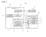
- FIG. 1 is a block diagram illustrating a configuration of a navigation apparatus 100 according to a first embodiment
- FIG. 2 is a schematic perspective view of the navigation apparatus 100 according to the first embodiment
- FIG. 3 (a) and 3(b) are schematic diagram for describing an operation of the navigation apparatus 100 according to the first embodiment, between these, FIG. 3 (a) is a view illustrating a user 1 which is viewed from a side direction (right side), and FIG. 3 (b) is a view illustrating the user 1 which is viewed from a front direction.
- the navigation apparatus 100 includes, a current position information acquisition unit (self-position acquisition unit 42) which acquires current position information, a travel direction determination unit (for example, route search unit 44) which determines a travel direction based on the acquired current position information and destination position information, a sound unit (for example, parametric speaker 30) which outputs a sound, and a sound control unit 41 which controls sound so that the sound may be heard to the user 1 ( FIGS. 3 (a) and 3(c) ) from the travel direction.
- the navigation apparatus 100 is a mobile terminal apparatus (a mobile phone, a Personal Digital Assistance (PDA), a small game machine, or the like).
- PDA Personal Digital Assistance
- the present embodiment describes an example in which the user carries the navigation apparatus 100 as a pedestrian. Hereinafter, it will be described in detail.
- the navigation apparatus 100 includes a control unit 40, a parametric speaker 30, and a self-position detection unit 10.
- the navigation apparatus 100 it is preferable that the navigation apparatus 100 have a communication function (an internet function, a phone call function, and the like).
- the self-position detection unit 10 detects its current position using a Global Positioning System (GPS) and the like.
- GPS Global Positioning System
- the control unit 40 includes the self-position acquisition unit 42, a destination information acquisition unit 43, the route search unit 44, and the sound control unit 41.
- the self-position acquisition unit 42 acquires information (hereinafter, current position information) indicating the current position detected by the self-position detection unit 10 from the self-position detection unit 10.
- the destination information acquisition unit 43 acquires information (hereinafter, destination information) about a destination.
- the destination information includes at least information indicating a destination position.
- the destination information may include various other information.
- the information of a position selected by an operation of the user 1 from map information downloaded by the navigation apparatus 100 according to the operation of the user 1 is acquired as the destination information, but the position information may be acquired by other method.
- the route search unit 44 searches a route necessary to reach the destination from the current position, based on the current position information acquired by the self-position acquisition unit 42, and the destination position information acquired by the destination information acquisition unit 43. Furthermore, the route search unit 44 determines a travel direction that has to be currently directed based on the route which searched.
- the sound control unit 41 includes a sound data processing unit 45 and a sound image localization processing unit 46, and controls the parametric speaker 30.
- the sound data processing unit 45 performs a regeneration process of the sound heard by the user 1 when the navigation operates.
- the sound image localization processing unit 46 performs a process to form (localize) a sound image on a travel direction position based on the user 1.
- the sound image localization processing unit 46 controls a directivity of the sound output from the parametric speaker 30 according to the travel direction determined by the route search unit 44, and allows the user 1 to hear the sound from the travel direction. In this manner, the user 1 can intuitively recognize whether to go in any direction, from a direction where the sound is heard.
- Each oscillation device 31 in the parametric speaker 30 is controlled by the sound image localization processing unit 46, and thereby the sound image can be formed in a desirable area. That is the sound image can be localized in a desirable area.
- the sound image localization processing unit 46 controls each oscillation device 31 so that the sound image 2 may be formed in front of the user 1 in a case where the travel direction is the front ( FIG. 3(a) ), controls each oscillation device 31 so that the sound image 2 may be formed on the left side of the user 1 in a case where the travel direction is left ( FIG. 3(b) ), and controls each oscillation device 31 so that the sound image 2 may be formed on the right side of the user 1 in a case where the travel direction is right ( FIG. 3(b) ).
- the sound image localization processing unit 46 stores in advance a phase value of ultrasonic wave output from each oscillation device 31 (alternatively, a relative shift amount value of the phase of the ultrasonic wave which is output from the each oscillation device 31), as a table, for each travel direction. Then, the sound image localization processing unit 46 extracts a value corresponding to the travel direction that has to be currently directed, from the table, and controls the phase of each oscillation device 31, based on the value.
- the sound image localization processing unit 46 controls the directivity of the parametric speaker 30 so that a private sound field with respect to the user 1 may be formed, and allows the sound to be heard by the user 1 only. Specifically, for example, the sound image is formed in an area within 30 cm from ears of the user 1.
- both of a distance between the navigation apparatus 100 which is the mobile terminal apparatus and ears of the user 1, and an ear direction which is viewed from the navigation apparatus 100 are maintained substantially constant, and thereby the navigation apparatus 100 performs a navigation operation.
- the navigation operation is performed in a state where the user 1 has the navigation apparatus 100 in his breast pocket.
- the distance and the like between the parametric speaker 30 and the ears of the user 1 are different from each other depending on a body size of the user 1, clothing design, or the like.
- the user 1 registers the distance in advance, and thereby the position where the sound image 2 is formed by the parametric speaker 30 may be configured to be properly adjusted.
- the user 1 may be able to fine-tune the directivity of the parametric speaker 30 so that a voice guide during the navigation operation may be easily heard.
- the parametric speaker 30 is configured to include the multiple oscillation devices 31 which oscillate respectively the ultrasonic wave, in an array type.
- the oscillation devices 31 are arranged in a matrix form.
- the parametric speaker 30 includes a signal generation unit 35 which generates an electrical signal input to each oscillation device 31.
- the navigation apparatus 100 includes a housing 101 in a rectangular parallelepiped shape.
- the multiple oscillation devices 31 are arranged on an end surface 101a in the longitudinal direction of the housing 101. Therefore, for example, the navigation apparatus 100 is put in the breast pocket so that the end surface 101a may be upward, and thereby the oscillation devices 31 are directed upward, in other words, towards the face of the user.
- FIG. 2 illustrates an example which describes the navigation apparatus 100 that is a simple rectangular shape, but the navigation apparatus 100 may be other form.
- the navigation apparatus 100 may be a folding type with a first housing and a second housing which are foldably connected to each other, and may be a slide type with the first housing and the second housing which are slidably connected to each other.
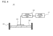
- FIG. 4 is a schematic diagram of the oscillation device 31.
- the oscillation device 31 includes a sheet-like vibration member 32, a vibrator 33, and a support member 34.
- the vibrator 33 is a piezoelectric vibrator, and is attached to one surface of the vibration member 32.
- the support member 34 supports an edge of the vibration member 32.
- the support member 34 is fixed to a circuit board (not illustrated) of the navigation apparatus 100 or the housing 101.
- the signal generation unit 35 and the sound control unit 41 configure an oscillation circuit which vibrate the vibrator 33 by inputting an oscillation signal to the vibrator 33, and vibrates sound wave using the vibrator 33 and the vibration member 32.
- the vibration member 32 is vibrated by a vibration generated by the vibrator 33, and oscillates the sound wave with a frequency equal to or more than 20 kHz, for example.
- the vibrator 33 oscillates the sound wave with a frequency equal to or more than 20 kHz, for example, by vibrating itself.
- the vibration member 32 adjusts a fundamental resonance frequency of the vibrator 33.
- the fundamental resonance frequency of a mechanical vibrator depends on a load weight and compliance.
- the compliance is a mechanical rigidity of the vibrator, and thus the fundamental resonance frequency of the vibrator 33 can be controlled by controlling the rigidity of the vibration member 32.
- the vibration member 32 have a longitudinal elastic modulus equal to or more than 1 Gpa and equal to or less than 500 Gpa, which is an index indicating the rigidity. In a case where the rigidity of the vibration member 32 is too low, or too high, there is a possibility of damaging characteristic or reliability of the mechanical vibrator.
- materials configuring the vibration member 32 are not particularly limited, if the materials have a high elastic modulus such as metal or resin with respect to the vibrator 33 formed by brittle materials. But it is preferable that the materials configuring the vibration member 32 be phosphor bronze, stainless or the like from the viewpoint of workability or a cost.
- a planar shape of the vibrator 33 is a circle.
- the planar shape of the vibrator 33 is not limited to a circle.
- an entire surface of the surface facing the vibration member 32 is fixed to the vibration member 32 using an adhesive agent.
- the entire surface of one surface of the vibrator 33 is restrained by the vibration member 32.
- the signal generation unit 35 generates an electric signal input to the vibrator 33, in other words, a modulation signal of the oscillation device 31.
- carrier wave of the modulation signal is ultrasonic wave with a frequency equal to or more than 20 kHz, specifically, ultrasonic wave with a frequency of 100 kHz, for example.
- the sound control unit 41 controls the signal generation unit 35 depending on a sound signal of the sound to be regenerated.
- FIG. 5 is a cross-sectional view illustrating a layer structure of a thickness direction of the vibrator 33.
- the vibrator 33 includes a piezoelectric body 36, an upper surface electrode 37, and a lower surface electrode 38.
- the piezoelectric body 36 is polarized in a thickness direction.
- Materials configuring the piezoelectric body 36 may be any one of inorganic materials and organic materials, as long as they are materials with piezoelectric effect. However, it is preferable that the materials configuring the piezoelectric body 36 be materials with a high electromechanical conversion efficiency such as lead zirconate titanate (PZT) or barium titanate (BaTiO3).
- PZT lead zirconate titanate
- BaTiO3 barium titanate
- a thickness h1 of the piezoelectric body is equal to or more than 10 um and equal to or less than 1 mm. In a case where the thickness h1 is less than 10 um, there occurs a possibility that the vibrator 33 is corrupted, while the oscillation device 31 is manufactured.
- the electromechanical conversion efficiency becomes too low, thereby there is a possibility that a sufficiently large vibration is not acquired.
- the reason is that, if the thickness of the vibrator 33 becomes thicker, electric field strength within the piezoelectric vibrator is reduced in inverse proportion.
- Materials configuring an upper surface electrode 37 and a lower surface electrode 38 are not particularly limited, but silver or a silver/palladium alloy can be used, for example.
- the silver is used as general electrode materials because of low resistance, and thus it has advantages in a manufacturing process or a cost.
- the silver/palladium alloy is low resistance materials with excellent oxidation resistance, and thus it has advantages from the viewpoint of the reliability.
- a thicknesses h2 of the upper surface electrode 37 and the lower surface electrode 38 are not particularly limited, but it is preferable that the thicknesses h2 be equal to or more than 1 um and equal to or less than 50 um.
- the thicknesses h2 are less than 1 um, it is difficult to uniformly form the upper surface electrode 37 and the lower surface electrode 38, and thus there is a possibility that the electromechanical conversion efficiency is lowered.
- the thicknesses of the upper surface electrode 37 and the lower surface electrode 38 are more than 100 um, the upper surface electrode 37 and the lower surface electrode 38 become a restraint surface with respect to the piezoelectric body 36, and there occurs a possibility that an energy conversion efficiency is lowered.
- the vibrator 33 can be formed to have an outer diameter of ⁇ 18 mm, an internal diameter of ⁇ 12 mm, and a thickness of 100 um.
- the silver/palladium alloy for example, weight ratio is 7 : 3 with thickness of 8 um can be used.
- the vibration member 32 can use a phosphor bronze with an outer diameter of ⁇ 20 mm and a thickness of 50 um (0.3 mm).
- the support member 34 functions as a case of the oscillation device 31, for example, is formed in a cylindrical shape (for example, circular cylindrical shape) with an outer diameter of ⁇ 22 mm, and an internal diameter of ⁇ 20 mm.
- the parametric speaker 30 emits ultrasonic wave (carrier wave) which is modulated by any one of AM modulation, DSB modulation, SSB modulation, FM modulation, into air from each of multiple oscillation devices 31, and generates an audible sound using non-linearity characteristic when the ultrasonic wave is propagated in the air.
- the term "non-linear” herein indicates a transition from a laminar flow to a turbulent flow when the Reynolds number expressed by the ratio of the inertial action and the viscous action of a flow increases. The sound wave is very slightly disturbed in the flow, and thus the sound wave is non-linearly propagated. Particularly, the non-linearity of the sound wave can be easily observed in an ultrasonic frequency band.
- the parametric speaker 30 has advantages of high sound directivity.
- the current position information is acquired by the self-position acquisition unit 42.
- the destination information is acquired by the destination information acquisition unit 43.
- the route search unit 44 searches the route based on the current position information and the destination information, and determines the travel direction to be currently travelled based on the searched route.
- the sound data processing unit 45 controls the parametric speaker 30, and thereby performing a sound regeneration process which is heard to the user when the navigation operates.
- the regenerated data of the sound may be stored to be retained by the navigation apparatus 100 in advance.
- the voice in this case is the information indicating the travel direction (please go ahead, please go to the right, or the like), however, alternatively, it may be music.
- the sound data may be input from outside to the navigation apparatus 100.
- the sound which is frequently downloaded (for example, downloaded from Web) from outside to the navigation apparatus 100 may be regenerated, and the sound which is currently heard at the destination, or the voice heard from the other party of a phone call may be regenerated.
- the destination information is received from a terminal apparatus (not illustrated) of a person already located in the destination, and the voice of talking with the person may be regenerated.
- the type of sound being regenerated may be arbitrarily selected by the user 1.
- FIG. 6 is a schematic plan view for describing the operation of the navigation apparatus 100 according to a first embodiment.
- FIG. 6 illustrates an operation when the user 1 heads for the destination 3. If the travel direction is changed according to a movement of the user 1, the position where the sound image 2 is localized is frequently changed. In other words, the user 1 can be guided to the destination by the frequent performance of such an operation.
- the parametric speaker 30 is controlled so that the sound may be heard to the user 1 from the travel direction, and thus the user 1 does not even know (even though inaudible) content of the voice, but can intuitively recognize the travel direction from the direction from which the sound is heard. In other words, an intuitive navigation is possible.
- the navigation operation is performed by forming private sound image 2 using the parametric speaker 30 which is a directional speaker, and thereby it is possible that the sound is not heard to people around the user 1.
- the travel direction is recognized to the user 1 by localizing the sound image 2 in the travel direction, it is not necessary that the content of the sound is always the information (please go ahead, please go to the right, or the like) indicating the travel direction, and the content of the sound can be configured of other useful information (advertisement and the like). For example, information on goods treated at the destination or service, music (song), the sound indicating a current status of a shop in the destination, and the like may be regenerated in the travel direction of the user 1.
- the navigation operation may be actively started by the user 1, but may be automatically started by the navigation apparatus 100, or may be started by a command of an apparatus outside the navigation apparatus 100.
- the navigation operation can be started by the command of the external apparatus with respect to the navigation apparatus 100.
- the information (the advertisement and the like) can be delivered to the user without discomfort.
- the information delivery is performed while situations around the user 1 are frequently changed, and thereby the information delivery accompanied by a realistic sense can be realized, and an advertisement effect can be increased.
- the navigation operation also can be performed in a case where the user is a driver of a vehicle or the like rather than a pedestrian.
- FIG. 7 is a block diagram illustrating a configuration of a navigation apparatus 100 according to a second embodiment
- FIG. 8 is a schematic perspective view of the navigation apparatus 100 according to the second embodiment.
- the navigation operation is performed so that a relative position between the navigation apparatus 100 and the ears of the user 1 may be maintained nearly constant.
- the second embodiment will be described with regard to an example in which it is assumed that the relative position between the navigation apparatus 100 and the ears of the user 1 may be changed.
- the navigation apparatus 100 includes multiple (for example, 2 units) imaging units(cameras) 21 and 22 which image respectively the user 1, and a relative position determination unit 47, in addition to the configuration of FIG. 1 .
- the imaging units 21 and 22 are arranged on the end surface 101a.
- Each of the imaging units 21 and 22 outputs respectively image data acquired by imaging of the user 1 to the relative position determination unit 47 in the control unit 40.
- the relative position determination unit 47 determines a relative position relationship between the ears of the user 1 and the parametric speaker 30 of the navigation apparatus 100, by performing analysis (image processing) with respect to the image input from the imaging units 21 and 22.
- the relative position relationship includes a distance between the ears of the user 1 and the parametric speaker 30, and a direction of the ears of the user 1 viewed from the parametric speaker 30.
- a position relationship detection unit which detects the relative position relationship between the user 1 and the parametric speaker 30 is configured of the imaging units 21 and 22 and the relative position determination unit 47.
- the sound image localization processing unit 46 corrects a position where the sound image 2 is formed according to the relative position relationship determined by the relative position determination unit 47. In other words, regardless of the relative position relationship between the ears of the user 1 and the parametric speaker 30 of the navigation apparatus 100, always, the parametric speaker 30 is controlled so that the sound image 2 may be formed in the position of the travel direction based on the user 1.
- the sound can be heard to the user 1 from the travel direction.
- the second embodiment describes with regard to an example in which the position relationship detection unit is configured of the imaging units 21 and 22 and the relative position determination unit 47, but the relative position determination unit may be configured of the imaging units 21 and 22, an ultrasonic wave sensor (sonar), and the relative position determination unit 47.
- the direction of the ears of the user 1 which is viewed from the parametric speaker 30 can be determined based on the image acquired by the imaging units 21 and 22, and the distance between the ears of the user 1 and the parametric speaker 30 can be determined based on a detection result using the ultrasonic wave sensor.
- FIG. 9 is a block diagram illustrating a configuration of a navigation apparatus 100 according to a third embodiment
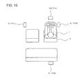
- FIG. 10 is a schematic plan view for describing a configuration of the navigation apparatus 100 according to the third embodiment.
- the sound unit is configured of multiple speakers 51 that are dispersed and arranged around a driver's seat in a vehicle, and the sound control unit 41 selectively outputs the sound from a speaker 51 corresponding to the travel direction, among the multiple speakers 51.
- the sound control unit 41 includes a speaker selection unit 48 instead of having no sound image localization processing unit 46.
- the speaker selection unit 48 selects the speaker 51 which performs a sound output for the navigation operation among the multiple speakers 51.
- the speakers 51 are configured of conductivity type electro-acoustic transducers.
- the conductivity type electro-acoustic transducers include respectively a permanent magnet, a voice coil, and a vibration film.
- the speaker 51a arranged in front of the driver's seat 5 in the vehicle, the speaker 51b arranged behind the driver's seat 5, the speaker 51c arranged on the left of the driver's seat 5, and the speaker 51d arranged on the right of the driver's seat 5 are included in the speakers 51, for example.
- the sound in a case where the travel direction is the front, the sound is selectively output from the speaker 51a among the speakers 51a to 51d.
- the sound in a case where the travel direction is the left, the sound is selectively output from the speaker 51c, and in a case where the travel direction is the right, the sound is selectively output from the speaker 51d.
- the travel direction in a case where the travel direction is the rear (for example, in a case where the user 1 receives a notification when the user 1 has gone too far before), the sound is selectively output from the speaker 51b.
- the sound can be heard from the travel direction to the user 1 which is the driver of the vehicle, even using such third embodiment, and thus the user 1 does not know even the content of the voice, but can recognize the travel direction.
- the speakers 51 can be arranged around the user 1 as many as necessary, and thus the sound output can be easily performed from 360° around the user 1, and for example, the sound output from the rear of the user 1 also can be performed.
- FIG. 11 is a schematic plan view for describing a configuration of a navigation apparatus 100 according to a fourth embodiment.
- the third embodiment describes with regard to an example in which the speaker 51 that is not the directional speaker is used, in a case where the navigation apparatus 100 is a vehicle mounting type.
- the sound images are formed in the position of the travel direction based on the user 1 using the directional speaker (for example, the parametric speaker 30).
- the configuration of the navigation apparatus 100 according to the present embodiment is the same as that illustrated in FIG. 1 .
- a private sound field can be formed around the user 1 that is the driver, and thereby an occupant sitting in a rear seat 6 or a passenger seat 7 cannot hear the sound generated by the navigation operation. Therefore, for example, in a case where a child 4 is sleeping in the rear seat 6, sleep of the child 4 cannot be disturbed.
- the oscillation device 31 of the navigation apparatus 100 according to the present embodiment includes a Micro Electro Mechanical System (MEMS) actuator 70 illustrated in FIG. 12 instead of the vibrator 33 ( FIG. 4 ).
- MEMS Micro Electro Mechanical System
- the navigation apparatus 100 according to the present embodiment is configured of the same as the navigation apparatus 100 according to the first to fourth embodiments.
- an actuating method of the MEMS actuator 70 is a piezoelectric method, and the MEMS actuator 70 has a structure with a piezoelectric thin film 72 interposed between an upper movable electrode layer 74 and a lower movable electrode layer 76.
- the MEMS actuator 70 is operated by inputting a signal to the upper movable electrode layer 74 and the lower movable electrode layer 76 from the signal generation unit 35.
- an aerosol deposition method is used, but it is not limited to this method.
- the piezoelectric thin film 72, the upper movable electrode layer 74 and the lower movable electrode layer 76 can be deposited respectively even on a curved surface.
- the actuation method of the MEMS actuator 70 may be an electrostatic method, an electromagnetic method, or a thermal conductivity method.
- FIG. 13 is a block diagram illustrating a configuration of a navigation apparatus 100 according to a sixth embodiment
- FIG. 14 is a schematic perspective view of the navigation apparatus 100 according to the sixth embodiment
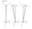
- FIGS. 15(a) to 15(c) are schematic diagrams for describing an operation of the navigation apparatus 100 according to the sixth embodiment.
- the position where the sound image is formed is controlled by controlling the phase of the ultrasonic wave output from each oscillation device 31 of the parametric speaker 30.
- an output direction of sound wave output from the oscillation device 31 is changed by actuators 39, and thereby the directivity of the parametric speaker 30 is controlled, and the position where the sound image is formed, in other words, the audible sound is demodulated, is controlled.
- the parametric speaker 30 includes one (one unit) oscillation device 31, multiple actuators 39 which change the direction of the oscillation device 31 and a support portion 39a on which the multiple actuators 39 are fixed.
- the support portion 39a is directly or indirectly fixed to the housing 101 of the navigation apparatus 100.
- the support portion 39a is formed in a flat type.
- the actuators 39 are piezoelectric elements, and are expanded and contracted by controlling an applied voltage.
- One end of each actuator 39 is fixed respectively to the support portion 39a, and the other end of each actuator 39 is fixed respectively to the oscillation device 31 such as a support member 34 of the oscillation 31.
- each actuator 39 is installed so as to vertically stand respectively on one surface of the support portion 39a.
- the number of actuators 39 can be configured to have two pieces or three pieces. In a case where three actuators 39 are installed, a freedom degree of direction adjustment of the oscillation device 31 is increased. Thus, in the present embodiment, as illustrated in FIG. 13 , it is preferable that three actuators 39 be included. An expansion and contraction operation of such actuators 39 is performed by an actuator control unit 49 of the control unit 40.
- the oscillation device 31 is arranged on an end surface 101a.
- FIG. 15 illustrates an operation in a case where there are two actuators 39, in order to simply describe.
- the output direction of the ultrasonic wave output from the oscillation device 31 becomes a direction opposite to the support portion 39a (in other words, the vibration member 32 of the oscillation device 31 and the support portion 39a are parallel to each other).
- the sound image 2 is formed in a front direction of the support portion 39a ( FIG. 15(a) ).
- any one of the actuators 39 is contracted (or any one of the actuators 39 is expanded), and thereby angle of the oscillation device 31 with respect to the support portion 39a can be changed, and the output of the ultrasonic wave output from the oscillation device 31 can be changed (in other words, the vibration member 32 can be arranged in an inclined state with respect to the support portion 39a).
- the sound image 2 is formed in an offset position from the front of the support portion 39a ( FIGS. 15 (b) and 15(c) ).
- each actuator 39 is properly expanded, and thereby the sound image 2 can be formed on the left of the user 1, or can be formed on the right of the user 1.
- the same effect as that of the first embodiment is acquired.
- the output direction of the sound wave output from the oscillation device 31 is changed by the actuators 39, and thereby forming position of the sound image 2 is changed.
- the parametric speaker 30 it is not necessary that the parametric speaker 30 have the multiple oscillation devices 31 in the array type, for example, it is no problem to have only one oscillation device 31.
- the route search unit 44 determines multiple travel directions, based on the current position information and each position information of the multiple destinations, and the sound control unit 41 may control the parametric speaker 30 so that the sound different from each other from each of the multiple travel direction may be heard to the user 1.
- the user 1 can selectively hear the information that the user 1 wants to hear, even if the sound different from each other from various directions is heard in a real life, the user 1 can selectively hear the information that the user 1 wants to hear even if the sound is heard respectively from multiple directions.
- each of the above-described embodiments has been described by assuming that the position of the destination is fixed, but the destination may be moved.
- the destination information acquisition unit 43 of one navigation apparatus 100 performs an operation to acquire the position information of the other navigation apparatus 100.
- the two users can intuitively recognize mutual positions, and thus the users can rapidly gather at a point by themselves.
- Such an operation is performed by using the mobile terminal apparatus (the navigation apparatus 100) while calling, and thereby a smooth gathering can be done.
- the users are not limited to two people, and may be three people or more.
- the destination information acquisition unit 43 in the navigation apparatus 100 of other one or multiple user may acquire the position information of the mobile terminal apparatus of the one certain user.
- the other user or the multiple users can intuitively recognize the user's position, and thus the other user or the multiple users can rapidly head for the point of destination of the user, and each user can easily gather.
- each user has the navigation apparatus 100 which is the mobile terminal apparatus, even in a case where the navigation apparatus 100 is the vehicle mounting type and each user moves in a vehicle, mutual position information is acquired, and a certain user's position information is acquired, in the same manner, thereby a rapid gathering can be done.
Abstract
Description
- The present invention relates to a navigation apparatus.
- A general navigation apparatus guides a user through a travel direction using a display or a voice (for example, Patent Document 1).
- In addition, in
Patent Document 2, a technique is described which localizes an sound image at a predetermined position using a parametric speaker. -
- [Patent Document 1] Japanese Unexamined Patent Publication No.
2010-91363 - [Patent Document 2] Japanese Unexamined Patent Publication No.
2010-68023 - In a general navigation apparatus, even in a case where a travel direction is guided by a voice, if a user does not understand voice content as a language after carefully heard the voice, the user cannot recognize the travel direction.
- An object of the present invention is to provide a navigation apparatus which enables a user to intuitively recognize a travel direction even if the user does not know the voice content.
- The present invention provides an navigation apparatus including: a current position information acquisition unit that acquires current position information, a travel direction determination unit that determines a travel direction based on the acquired current position information and destination position information, a sound unit that outputs a sound, and a sound control unit that controls the sound unit so that the sound can be heard to a user from the travel direction.
- According to the present invention, a user can intuitively recognize the travel direction even if the user does not know the voice content.
- The above-described object, other objects, features, and advantages will become more apparent from the preferred embodiments and the accompanied drawings which are described below.
-
-
FIG. 1 is a block diagram illustrating a configuration of a navigation apparatus according to a first embodiment. -
FIG. 2 is a schematic perspective view of the navigation apparatus according to the first embodiment. -
FIGS. 3(a) and 3(b) are schematic diagrams for describing an operation of the navigation apparatus according to the first embodiment. -
FIG. 4 is a schematic diagram of an oscillation device which is included in the navigation apparatus according to the first embodiment. -
FIG. 5 is a cross-sectional view illustrating a layer structure of a vibrator. -
FIG. 6 is a schematic plan view for describing an operation of the navigation apparatus according to the first embodiment. -
FIG. 7 is a block diagram illustrating a configuration of the navigation apparatus according to a second embodiment. -
FIG. 8 is a schematic perspective view of the navigation apparatus according to the second embodiment. -
FIG. 9 is a block diagram illustrating a configuration of a navigation apparatus according to a third embodiment. -
FIG. 10 is a schematic plan view for describing a configuration of the navigation apparatus according to the third embodiment. -
FIG. 11 is a schematic plan view for describing a configuration of a navigation apparatus according to a fourth embodiment. -
FIG. 12 is an exploded perspective view illustrating a configuration of a MEMS actuator which is used as a vibrator of an oscillation device included in a navigation apparatus according to a fifth embodiment. -
FIG. 13 is a block diagram illustrating a configuration of a navigation apparatus according to a sixth embodiment. -
FIG. 14 is a schematic perspective view of the navigation apparatus according to the sixth embodiment. -
FIGS. 15(a) to 15(c) are schematic diagrams for describing an operation of the navigation apparatus according to the sixth embodiment. - Hereinafter, embodiments according to the present invention will be described by using drawings. In addition, in all the drawings, the same configuration elements are denoted by the same reference numerals, and then will not be repeated.
-
FIG. 1 is a block diagram illustrating a configuration of anavigation apparatus 100 according to a first embodiment, andFIG. 2 is a schematic perspective view of thenavigation apparatus 100 according to the first embodiment.FIG. 3 (a) and 3(b) are schematic diagram for describing an operation of thenavigation apparatus 100 according to the first embodiment, between these,FIG. 3 (a) is a view illustrating auser 1 which is viewed from a side direction (right side), andFIG. 3 (b) is a view illustrating theuser 1 which is viewed from a front direction. - The
navigation apparatus 100 according to the present embodiment includes, a current position information acquisition unit (self-position acquisition unit 42) which acquires current position information, a travel direction determination unit (for example, route search unit 44) which determines a travel direction based on the acquired current position information and destination position information, a sound unit (for example, parametric speaker 30) which outputs a sound, and asound control unit 41 which controls sound so that the sound may be heard to the user 1 (FIGS. 3 (a) and 3(c) ) from the travel direction. In addition, in the present embodiment, thenavigation apparatus 100 is a mobile terminal apparatus (a mobile phone, a Personal Digital Assistance (PDA), a small game machine, or the like). In addition, the present embodiment describes an example in which the user carries thenavigation apparatus 100 as a pedestrian. Hereinafter, it will be described in detail. - As illustrated in
FIG. 1 , thenavigation apparatus 100 includes acontrol unit 40, aparametric speaker 30, and a self-position detection unit 10. In addition, for example, it is preferable that thenavigation apparatus 100 have a communication function (an internet function, a phone call function, and the like). - For example, the self-
position detection unit 10 detects its current position using a Global Positioning System (GPS) and the like. - The
control unit 40 includes the self-position acquisition unit 42, a destinationinformation acquisition unit 43, theroute search unit 44, and thesound control unit 41. - The self-
position acquisition unit 42 acquires information (hereinafter, current position information) indicating the current position detected by the self-position detection unit 10 from the self-position detection unit 10. - The destination
information acquisition unit 43 acquires information (hereinafter, destination information) about a destination. The destination information includes at least information indicating a destination position. However, the destination information may include various other information. - For example, as a method of acquiring the destination information by the destination
information acquisition unit 43, the information of a position selected by an operation of theuser 1 from map information downloaded by thenavigation apparatus 100 according to the operation of theuser 1 is acquired as the destination information, but the position information may be acquired by other method. - The
route search unit 44 searches a route necessary to reach the destination from the current position, based on the current position information acquired by the self-position acquisition unit 42, and the destination position information acquired by the destinationinformation acquisition unit 43. Furthermore, theroute search unit 44 determines a travel direction that has to be currently directed based on the route which searched. - The
sound control unit 41 includes a sounddata processing unit 45 and a sound imagelocalization processing unit 46, and controls theparametric speaker 30. - The sound
data processing unit 45 performs a regeneration process of the sound heard by theuser 1 when the navigation operates. - The sound image
localization processing unit 46 performs a process to form (localize) a sound image on a travel direction position based on theuser 1. In other words, the sound imagelocalization processing unit 46 controls a directivity of the sound output from theparametric speaker 30 according to the travel direction determined by theroute search unit 44, and allows theuser 1 to hear the sound from the travel direction. In this manner, theuser 1 can intuitively recognize whether to go in any direction, from a direction where the sound is heard. - Each
oscillation device 31 in theparametric speaker 30 is controlled by the sound imagelocalization processing unit 46, and thereby the sound image can be formed in a desirable area. That is the sound image can be localized in a desirable area.
Specifically, the sound imagelocalization processing unit 46 controls eachoscillation device 31 so that thesound image 2 may be formed in front of theuser 1 in a case where the travel direction is the front (FIG. 3(a) ), controls eachoscillation device 31 so that thesound image 2 may be formed on the left side of theuser 1 in a case where the travel direction is left (FIG. 3(b) ), and controls eachoscillation device 31 so that thesound image 2 may be formed on the right side of theuser 1 in a case where the travel direction is right (FIG. 3(b) ).
In order to realize such an operation, for example, the sound imagelocalization processing unit 46 stores in advance a phase value of ultrasonic wave output from each oscillation device 31 (alternatively, a relative shift amount value of the phase of the ultrasonic wave which is output from the each oscillation device 31), as a table, for each travel direction. Then, the sound imagelocalization processing unit 46 extracts a value corresponding to the travel direction that has to be currently directed, from the table, and controls the phase of eachoscillation device 31, based on the value. - In addition, the sound image
localization processing unit 46 controls the directivity of theparametric speaker 30 so that a private sound field with respect to theuser 1 may be formed, and allows the sound to be heard by theuser 1 only. Specifically, for example, the sound image is formed in an area within 30 cm from ears of theuser 1. - In the present embodiment, it is assumed that both of a distance between the
navigation apparatus 100 which is the mobile terminal apparatus and ears of theuser 1, and an ear direction which is viewed from thenavigation apparatus 100 are maintained substantially constant, and thereby thenavigation apparatus 100 performs a navigation operation. Specifically, for example, it is assumed that the navigation operation is performed in a state where theuser 1 has thenavigation apparatus 100 in his breast pocket. However, even in this case, there is a case where the distance and the like between theparametric speaker 30 and the ears of theuser 1 are different from each other depending on a body size of theuser 1, clothing design, or the like. For this reason, theuser 1 registers the distance in advance, and thereby the position where thesound image 2 is formed by theparametric speaker 30 may be configured to be properly adjusted. Alternatively, theuser 1 may be able to fine-tune the directivity of theparametric speaker 30 so that a voice guide during the navigation operation may be easily heard. - For example, the
parametric speaker 30 is configured to include themultiple oscillation devices 31 which oscillate respectively the ultrasonic wave, in an array type. For example, theoscillation devices 31 are arranged in a matrix form. Furthermore, theparametric speaker 30 includes asignal generation unit 35 which generates an electrical signal input to eachoscillation device 31. - As illustrated in
FIG. 2 , for example, thenavigation apparatus 100 includes ahousing 101 in a rectangular parallelepiped shape. Themultiple oscillation devices 31 are arranged on anend surface 101a in the longitudinal direction of thehousing 101. Therefore, for example, thenavigation apparatus 100 is put in the breast pocket so that theend surface 101a may be upward, and thereby theoscillation devices 31 are directed upward, in other words, towards the face of the user. - In addition,
FIG. 2 illustrates an example which describes thenavigation apparatus 100 that is a simple rectangular shape, but thenavigation apparatus 100 may be other form. For example, thenavigation apparatus 100 may be a folding type with a first housing and a second housing which are foldably connected to each other, and may be a slide type with the first housing and the second housing which are slidably connected to each other. -
FIG. 4 is a schematic diagram of theoscillation device 31. - For example, the
oscillation device 31 includes a sheet-like vibration member 32, avibrator 33, and asupport member 34. For example, thevibrator 33 is a piezoelectric vibrator, and is attached to one surface of thevibration member 32. Thesupport member 34 supports an edge of thevibration member 32. In addition, for example, thesupport member 34 is fixed to a circuit board (not illustrated) of thenavigation apparatus 100 or thehousing 101.
Thesignal generation unit 35 and thesound control unit 41 configure an oscillation circuit which vibrate thevibrator 33 by inputting an oscillation signal to thevibrator 33, and vibrates sound wave using thevibrator 33 and thevibration member 32. - The
vibration member 32 is vibrated by a vibration generated by thevibrator 33, and oscillates the sound wave with a frequency equal to or more than 20 kHz, for example. In addition, thevibrator 33 oscillates the sound wave with a frequency equal to or more than 20 kHz, for example, by vibrating itself. In addition, thevibration member 32 adjusts a fundamental resonance frequency of thevibrator 33. The fundamental resonance frequency of a mechanical vibrator depends on a load weight and compliance. The compliance is a mechanical rigidity of the vibrator, and thus the fundamental resonance frequency of thevibrator 33 can be controlled by controlling the rigidity of thevibration member 32. In addition, it is preferable that thickness of thevibration member 32 be equal to or more than 5 um and equal to or less than 500 um. In addition, it is preferable that thevibration member 32 have a longitudinal elastic modulus equal to or more than 1 Gpa and equal to or less than 500 Gpa, which is an index indicating the rigidity. In a case where the rigidity of thevibration member 32 is too low, or too high, there is a possibility of damaging characteristic or reliability of the mechanical vibrator. In addition, materials configuring thevibration member 32 are not particularly limited, if the materials have a high elastic modulus such as metal or resin with respect to thevibrator 33 formed by brittle materials. But it is preferable that the materials configuring thevibration member 32 be phosphor bronze, stainless or the like from the viewpoint of workability or a cost. - In the present embodiment, a planar shape of the
vibrator 33 is a circle. However, the planar shape of thevibrator 33 is not limited to a circle. In thevibrator 33, an entire surface of the surface facing thevibration member 32 is fixed to thevibration member 32 using an adhesive agent. Thus, the entire surface of one surface of thevibrator 33 is restrained by thevibration member 32. - The
signal generation unit 35 generates an electric signal input to thevibrator 33, in other words, a modulation signal of theoscillation device 31. For example, carrier wave of the modulation signal is ultrasonic wave with a frequency equal to or more than 20 kHz, specifically, ultrasonic wave with a frequency of 100 kHz, for example. Thesound control unit 41 controls thesignal generation unit 35 depending on a sound signal of the sound to be regenerated. -
FIG. 5 is a cross-sectional view illustrating a layer structure of a thickness direction of thevibrator 33. Thevibrator 33 includes apiezoelectric body 36, anupper surface electrode 37, and alower surface electrode 38. - The
piezoelectric body 36 is polarized in a thickness direction. Materials configuring thepiezoelectric body 36 may be any one of inorganic materials and organic materials, as long as they are materials with piezoelectric effect. However, it is preferable that the materials configuring thepiezoelectric body 36 be materials with a high electromechanical conversion efficiency such as lead zirconate titanate (PZT) or barium titanate (BaTiO3). For example, a thickness h1 of the piezoelectric body is equal to or more than 10 um and equal to or less than 1 mm. In a case where the thickness h1 is less than 10 um, there occurs a possibility that thevibrator 33 is corrupted, while theoscillation device 31 is manufactured. In addition, in a case where the thickness h1 is more than 1 mm, the electromechanical conversion efficiency becomes too low, thereby there is a possibility that a sufficiently large vibration is not acquired. The reason is that, if the thickness of thevibrator 33 becomes thicker, electric field strength within the piezoelectric vibrator is reduced in inverse proportion. - Materials configuring an
upper surface electrode 37 and alower surface electrode 38 are not particularly limited, but silver or a silver/palladium alloy can be used, for example. The silver is used as general electrode materials because of low resistance, and thus it has advantages in a manufacturing process or a cost. The silver/palladium alloy is low resistance materials with excellent oxidation resistance, and thus it has advantages from the viewpoint of the reliability. In addition, a thicknesses h2 of theupper surface electrode 37 and thelower surface electrode 38 are not particularly limited, but it is preferable that the thicknesses h2 be equal to or more than 1 um and equal to or less than 50 um. In a case where the thicknesses h2 are less than 1 um, it is difficult to uniformly form theupper surface electrode 37 and thelower surface electrode 38, and thus there is a possibility that the electromechanical conversion efficiency is lowered. In addition, in a case where the thicknesses of theupper surface electrode 37 and thelower surface electrode 38 are more than 100 um, theupper surface electrode 37 and thelower surface electrode 38 become a restraint surface with respect to thepiezoelectric body 36, and there occurs a possibility that an energy conversion efficiency is lowered. - The
vibrator 33 can be formed to have an outer diameter of Φ 18 mm, an internal diameter of Φ 12 mm, and a thickness of 100 um. In addition, for example, as theupper surface electrode 37 and thelower surface electrode 38, the silver/palladium alloy (for example, weight ratio is 7 : 3) with thickness of 8 um can be used. In addition, thevibration member 32 can use a phosphor bronze with an outer diameter of Φ 20 mm and a thickness of 50 um (0.3 mm). Thesupport member 34 functions as a case of theoscillation device 31, for example, is formed in a cylindrical shape (for example, circular cylindrical shape) with an outer diameter of Φ 22 mm, and an internal diameter of Φ 20 mm. - The
parametric speaker 30 emits ultrasonic wave (carrier wave) which is modulated by any one of AM modulation, DSB modulation, SSB modulation, FM modulation, into air from each ofmultiple oscillation devices 31, and generates an audible sound using non-linearity characteristic when the ultrasonic wave is propagated in the air. The term "non-linear" herein indicates a transition from a laminar flow to a turbulent flow when the Reynolds number expressed by the ratio of the inertial action and the viscous action of a flow increases. The sound wave is very slightly disturbed in the flow, and thus the sound wave is non-linearly propagated. Particularly, the non-linearity of the sound wave can be easily observed in an ultrasonic frequency band. Then, in a case where the ultrasonic wave is emitted into the air, higher harmonic wave accompanied by the non-linearity of the sound wave is remarkably generated. In addition, the sound wave is in a sparse and dense state in which light and shade is generated in a molecular density in the air. Then, in a case where air molecules require more time in being restored than being compressed, air which cannot be restored after being compressed collides with the air molecules which are continuously propagated, and thereby impulse wave is generated. The audible sound is generated by the impulse wave, in other words, the audible sound is regenerated (demodulated). Theparametric speaker 30 has advantages of high sound directivity. - Next, a series of operations will be described.
- First, the current position information is acquired by the self-
position acquisition unit 42. In addition, the destination information is acquired by the destinationinformation acquisition unit 43. - Next, the
route search unit 44 searches the route based on the current position information and the destination information, and determines the travel direction to be currently travelled based on the searched route. - Next, the sound
data processing unit 45 controls theparametric speaker 30, and thereby performing a sound regeneration process which is heard to the user when the navigation operates. - Here, the regenerated data of the sound (sound data) may be stored to be retained by the
navigation apparatus 100 in advance. For example, the voice in this case is the information indicating the travel direction (please go ahead, please go to the right, or the like), however, alternatively, it may be music.
In addition, the sound data may be input from outside to thenavigation apparatus 100. For example, the sound which is frequently downloaded (for example, downloaded from Web) from outside to thenavigation apparatus 100 may be regenerated, and the sound which is currently heard at the destination, or the voice heard from the other party of a phone call may be regenerated. More specifically, for example, the destination information is received from a terminal apparatus (not illustrated) of a person already located in the destination, and the voice of talking with the person may be regenerated.
In addition, the type of sound being regenerated may be arbitrarily selected by theuser 1. - In addition, in parallel with the regeneration process of the sound
data processing unit 45, the sound imagelocalization processing unit 46 controls the directivity of the sound output from theparametric speaker 30, and allows theuser 1 to hear the sound from the travel direction.
FIG. 6 is a schematic plan view for describing the operation of thenavigation apparatus 100 according to a first embodiment.FIG. 6 illustrates an operation when theuser 1 heads for thedestination 3.
If the travel direction is changed according to a movement of theuser 1, the position where thesound image 2 is localized is frequently changed. In other words, theuser 1 can be guided to the destination by the frequent performance of such an operation. - According to the first embodiment described above, the
parametric speaker 30 is controlled so that the sound may be heard to theuser 1 from the travel direction, and thus theuser 1 does not even know (even though inaudible) content of the voice, but can intuitively recognize the travel direction from the direction from which the sound is heard. In other words, an intuitive navigation is possible. - In addition, the navigation operation is performed by forming private
sound image 2 using theparametric speaker 30 which is a directional speaker, and thereby it is possible that the sound is not heard to people around theuser 1. - In addition, since the travel direction is recognized to the
user 1 by localizing thesound image 2 in the travel direction, it is not necessary that the content of the sound is always the information (please go ahead, please go to the right, or the like) indicating the travel direction, and the content of the sound can be configured of other useful information (advertisement and the like). For example, information on goods treated at the destination or service, music (song), the sound indicating a current status of a shop in the destination, and the like may be regenerated in the travel direction of theuser 1. - In addition, the navigation operation may be actively started by the
user 1, but may be automatically started by thenavigation apparatus 100, or may be started by a command of an apparatus outside thenavigation apparatus 100. For example, in a case where theuser 1 passes through a specified area while walking down a street, the navigation operation can be started by the command of the external apparatus with respect to thenavigation apparatus 100. Even in this case, the information (the advertisement and the like) can be delivered to the user without discomfort. In addition, as a result of the user's movement guided by the navigation operation, the information delivery is performed while situations around theuser 1 are frequently changed, and thereby the information delivery accompanied by a realistic sense can be realized, and an advertisement effect can be increased. - In addition, even in a case where the
navigation apparatus 100 is a mobile type as is the present embodiment, the navigation operation also can be performed in a case where the user is a driver of a vehicle or the like rather than a pedestrian. -
FIG. 7 is a block diagram illustrating a configuration of anavigation apparatus 100 according to a second embodiment, andFIG. 8 is a schematic perspective view of thenavigation apparatus 100 according to the second embodiment.
In the first embodiment described above, it is assumed that the navigation operation is performed so that a relative position between thenavigation apparatus 100 and the ears of theuser 1 may be maintained nearly constant. On the other hand, the second embodiment will be described with regard to an example in which it is assumed that the relative position between thenavigation apparatus 100 and the ears of theuser 1 may be changed. - As illustrated in
FIG. 7 , thenavigation apparatus 100 according to the present embodiment includes multiple (for example, 2 units) imaging units(cameras) 21 and 22 which image respectively theuser 1, and a relativeposition determination unit 47, in addition to the configuration ofFIG. 1 . For example, as illustrated inFIG. 8 , theimaging units end surface 101a. - Each of the
imaging units user 1 to the relativeposition determination unit 47 in thecontrol unit 40.
The relativeposition determination unit 47 determines a relative position relationship between the ears of theuser 1 and theparametric speaker 30 of thenavigation apparatus 100, by performing analysis (image processing) with respect to the image input from theimaging units user 1 and theparametric speaker 30, and a direction of the ears of theuser 1 viewed from theparametric speaker 30.
In addition, a position relationship detection unit which detects the relative position relationship between theuser 1 and theparametric speaker 30 is configured of theimaging units position determination unit 47. - The sound image
localization processing unit 46 corrects a position where thesound image 2 is formed according to the relative position relationship determined by the relativeposition determination unit 47. In other words, regardless of the relative position relationship between the ears of theuser 1 and theparametric speaker 30 of thenavigation apparatus 100, always, theparametric speaker 30 is controlled so that thesound image 2 may be formed in the position of the travel direction based on theuser 1. - According to the second embodiment described above, regardless of the relative position relationship between the ears of the
user 1 and theparametric speaker 30 of thenavigation apparatus 100, the sound can be heard to theuser 1 from the travel direction. - In addition, the second embodiment describes with regard to an example in which the position relationship detection unit is configured of the
imaging units position determination unit 47, but the relative position determination unit may be configured of theimaging units position determination unit 47. In this case, the direction of the ears of theuser 1 which is viewed from theparametric speaker 30 can be determined based on the image acquired by theimaging units user 1 and theparametric speaker 30 can be determined based on a detection result using the ultrasonic wave sensor. -
FIG. 9 is a block diagram illustrating a configuration of anavigation apparatus 100 according to a third embodiment, andFIG. 10 is a schematic plan view for describing a configuration of thenavigation apparatus 100 according to the third embodiment. - Each of the above-described embodiments describes with regard to an example in which the
navigation apparatus 100 is the mobile terminal apparatus, but the present embodiment will be described with regard to an example in which thenavigation apparatus 100 is a vehicle mounting type. - In the third embodiment, the sound unit is configured of
multiple speakers 51 that are dispersed and arranged around a driver's seat in a vehicle, and thesound control unit 41 selectively outputs the sound from aspeaker 51 corresponding to the travel direction, among themultiple speakers 51. In other words, thesound control unit 41 includes aspeaker selection unit 48 instead of having no sound imagelocalization processing unit 46. Thespeaker selection unit 48 selects thespeaker 51 which performs a sound output for the navigation operation among themultiple speakers 51. - Each of the above-described embodiments describes with regard to an example in which the sound unit is the directional speaker (for example, the parametric speaker 30). On the other hand, in the present embodiment, for example, the
speakers 51 are configured of conductivity type electro-acoustic transducers. The conductivity type electro-acoustic transducers include respectively a permanent magnet, a voice coil, and a vibration film.
As illustrated inFIG. 10 , as an example, thespeaker 51a arranged in front of the driver'sseat 5 in the vehicle, thespeaker 51b arranged behind the driver'sseat 5, thespeaker 51c arranged on the left of the driver'sseat 5, and thespeaker 51d arranged on the right of the driver'sseat 5 are included in thespeakers 51, for example. - In the present embodiment, in a case where the travel direction is the front, the sound is selectively output from the
speaker 51a among thespeakers 51a to 51d. In the same manner, in a case where the travel direction is the left, the sound is selectively output from thespeaker 51c, and in a case where the travel direction is the right, the sound is selectively output from thespeaker 51d. In addition, in a case where the travel direction is the rear (for example, in a case where theuser 1 receives a notification when theuser 1 has gone too far before), the sound is selectively output from thespeaker 51b. - The sound can be heard from the travel direction to the
user 1 which is the driver of the vehicle, even using such third embodiment, and thus theuser 1 does not know even the content of the voice, but can recognize the travel direction.
In addition, thespeakers 51 can be arranged around theuser 1 as many as necessary, and thus the sound output can be easily performed from 360° around theuser 1, and for example, the sound output from the rear of theuser 1 also can be performed. -
FIG. 11 is a schematic plan view for describing a configuration of anavigation apparatus 100 according to a fourth embodiment. - The third embodiment describes with regard to an example in which the
speaker 51 that is not the directional speaker is used, in a case where thenavigation apparatus 100 is a vehicle mounting type. On the other hand, in the fourth embodiment, even in a case where thenavigation apparatus 100 is the vehicle mounting type, the sound images are formed in the position of the travel direction based on theuser 1 using the directional speaker (for example, the parametric speaker 30). In addition, the configuration of thenavigation apparatus 100 according to the present embodiment is the same as that illustrated inFIG. 1 . - In the present embodiment, a private sound field can be formed around the
user 1 that is the driver, and thereby an occupant sitting in arear seat 6 or apassenger seat 7 cannot hear the sound generated by the navigation operation. Therefore, for example, in a case where achild 4 is sleeping in therear seat 6, sleep of thechild 4 cannot be disturbed. - The
oscillation device 31 of thenavigation apparatus 100 according to the present embodiment includes a Micro Electro Mechanical System (MEMS)actuator 70 illustrated inFIG. 12 instead of the vibrator 33 (FIG. 4 ). In other respects, thenavigation apparatus 100 according to the present embodiment is configured of the same as thenavigation apparatus 100 according to the first to fourth embodiments. - In the example illustrated in
FIG. 12 , an actuating method of theMEMS actuator 70 is a piezoelectric method, and theMEMS actuator 70 has a structure with a piezoelectricthin film 72 interposed between an uppermovable electrode layer 74 and a lowermovable electrode layer 76. TheMEMS actuator 70 is operated by inputting a signal to the uppermovable electrode layer 74 and the lowermovable electrode layer 76 from thesignal generation unit 35. In a manufacture of theMEMS actuator 70, for example, an aerosol deposition method is used, but it is not limited to this method. However, in a case where the aerosol deposition method is used, it is preferable that the piezoelectricthin film 72, the uppermovable electrode layer 74 and the lowermovable electrode layer 76 can be deposited respectively even on a curved surface. In addition, the actuation method of theMEMS actuator 70 may be an electrostatic method, an electromagnetic method, or a thermal conductivity method. -
FIG. 13 is a block diagram illustrating a configuration of anavigation apparatus 100 according to a sixth embodiment,FIG. 14 is a schematic perspective view of thenavigation apparatus 100 according to the sixth embodiment, andFIGS. 15(a) to 15(c) are schematic diagrams for describing an operation of thenavigation apparatus 100 according to the sixth embodiment. - The above-described first embodiment has been described with regard to an example in which the position where the sound image is formed is controlled by controlling the phase of the ultrasonic wave output from each
oscillation device 31 of theparametric speaker 30.
On the other hand, in the present embodiment, an output direction of sound wave output from theoscillation device 31 is changed byactuators 39, and thereby the directivity of theparametric speaker 30 is controlled, and the position where the sound image is formed, in other words, the audible sound is demodulated, is controlled. - As illustrated in
FIGS. 15 (a) to 15 (c) , in case of the present embodiment, for example, theparametric speaker 30 includes one (one unit)oscillation device 31,multiple actuators 39 which change the direction of theoscillation device 31 and asupport portion 39a on which themultiple actuators 39 are fixed. - The
support portion 39a is directly or indirectly fixed to thehousing 101 of thenavigation apparatus 100. For example, thesupport portion 39a is formed in a flat type. - For example, the
actuators 39 are piezoelectric elements, and are expanded and contracted by controlling an applied voltage. One end of each actuator 39 is fixed respectively to thesupport portion 39a, and the other end of each actuator 39 is fixed respectively to theoscillation device 31 such as asupport member 34 of theoscillation 31. For example, each actuator 39 is installed so as to vertically stand respectively on one surface of thesupport portion 39a. - The number of
actuators 39 can be configured to have two pieces or three pieces. In a case where threeactuators 39 are installed, a freedom degree of direction adjustment of theoscillation device 31 is increased. Thus, in the present embodiment, as illustrated inFIG. 13 , it is preferable that threeactuators 39 be included. An expansion and contraction operation ofsuch actuators 39 is performed by anactuator control unit 49 of thecontrol unit 40. - In addition, as illustrated in
FIG. 14 , in the present embodiment, for example, theoscillation device 31 is arranged on anend surface 101a. -
FIG. 15 illustrates an operation in a case where there are twoactuators 39, in order to simply describe. - When lengths of each actuator 39 are the same, the output direction of the ultrasonic wave output from the
oscillation device 31 becomes a direction opposite to thesupport portion 39a (in other words, thevibration member 32 of theoscillation device 31 and thesupport portion 39a are parallel to each other). Thus, thesound image 2 is formed in a front direction of thesupport portion 39a (FIG. 15(a) ). - In addition, any one of the
actuators 39 is contracted (or any one of theactuators 39 is expanded), and thereby angle of theoscillation device 31 with respect to thesupport portion 39a can be changed, and the output of the ultrasonic wave output from theoscillation device 31 can be changed (in other words, thevibration member 32 can be arranged in an inclined state with respect to thesupport portion 39a). Thus, thesound image 2 is formed in an offset position from the front of thesupport portion 39a (FIGS. 15 (b) and 15(c) ). - Thus, in the present embodiment, each actuator 39 is properly expanded, and thereby the
sound image 2 can be formed on the left of theuser 1, or can be formed on the right of theuser 1. - According to the sixth embodiment, the same effect as that of the first embodiment is acquired.
In addition, in case of the sixth embodiment, the output direction of the sound wave output from theoscillation device 31 is changed by theactuators 39, and thereby forming position of thesound image 2 is changed. Thus, it is not necessary that theparametric speaker 30 have themultiple oscillation devices 31 in the array type, for example, it is no problem to have only oneoscillation device 31. - Each of the above-described embodiments has been described by assuming that there is one destination, and the sound is heard only from one travel direction at one time, but there may be multiple destinations and the sound may be heard from the travel direction corresponding to the destinations at the same time. In other words, the
route search unit 44 determines multiple travel directions, based on the current position information and each position information of the multiple destinations, and thesound control unit 41 may control theparametric speaker 30 so that the sound different from each other from each of the multiple travel direction may be heard to theuser 1. In this case, just as theuser 1 can selectively hear the information that theuser 1 wants to hear, even if the sound different from each other from various directions is heard in a real life, theuser 1 can selectively hear the information that theuser 1 wants to hear even if the sound is heard respectively from multiple directions. - In addition, each of the above-described embodiments has been described by assuming that the travel direction is a certain place in the horizontal direction, but the destination may be an upper portion (for example, climbing stairs) or a lower portion (for example, climbing down the stairs).
- In addition, each of the above-described embodiments has been described by assuming that the position of the destination is fixed, but the destination may be moved. For example, while each of two users with the
navigation apparatus 100 that is the mobile terminal apparatus such as that described in the first embodiment moves, the destinationinformation acquisition unit 43 of onenavigation apparatus 100 performs an operation to acquire the position information of theother navigation apparatus 100. As a result of the operation, the two users can intuitively recognize mutual positions, and thus the users can rapidly gather at a point by themselves. Such an operation is performed by using the mobile terminal apparatus (the navigation apparatus 100) while calling, and thereby a smooth gathering can be done. In addition, the users are not limited to two people, and may be three people or more.
In addition, while one certain user with the mobile terminal apparatus moves, the destinationinformation acquisition unit 43 in thenavigation apparatus 100 of other one or multiple user (s) may acquire the position information of the mobile terminal apparatus of the one certain user. In this case, the other user or the multiple users can intuitively recognize the user's position, and thus the other user or the multiple users can rapidly head for the point of destination of the user, and each user can easily gather.
In addition, it is not limited to that each user has thenavigation apparatus 100 which is the mobile terminal apparatus, even in a case where thenavigation apparatus 100 is the vehicle mounting type and each user moves in a vehicle, mutual position information is acquired, and a certain user's position information is acquired, in the same manner, thereby a rapid gathering can be done. - This application claims the priority based on Japanese Patent Application No.
2011-013972 filed on January 26, 2011
Claims (9)
- A navigation apparatus comprising:a current position information acquisition unit that acquires current position information;a travel direction determination unit that determines a travel direction based on the acquired current position information and destination position information;a sound unit that outputs a sound; anda sound control unit that controls the sound unit so that the sound can be heard to a user from the travel direction.
- The navigation apparatus according to claim 1,
wherein the sound unit is configured of a directional speaker, and
wherein the sound control unit forms a sound image of the sound using the sound unit in a position of the travel direction based on the user. - The navigation apparatus according to claim 2,
wherein the directional speaker is a parametric speaker. - The navigation apparatus according to any one of claims 1 to 3,
wherein a position relationship detection unit that detects a relative position relationship between the user and the sound unit is further comprised, and
wherein the sound control unit controls the sound unit according to the relative position relationship detected by the position relationship detection unit. - The navigation apparatus according to claim 2 or 3,
wherein the sound control unit forms the sound image at an area within 30 cm based on the user's ear. - The navigation apparatus according to any one of claims 1 to 5,
wherein the navigation apparatus is a mobile terminal apparatus. - The navigation apparatus according to claim 1,
wherein the sound unit is configured of a plurality of speakers that are dispersed and arranged around the driver' s seat in a vehicle, and
wherein the sound control unit selectively outputs the sound from the speaker corresponding to the travel direction among the plurality of speakers. - The navigation apparatus according to any one of claims 1 to 7,
wherein the sound control unit allows the sound unit output the sound for transmitting information except for information indicating the travel direction to the user. - The navigation apparatus according to any one of claims 1 to 8,
wherein the travel direction determination unit determines a plurality of travel directions based on the current position information, and each position information of a plurality of destinations, and
wherein the sound control unit controls the sound unit so that the sound mutually different from each of the plurality of travel directions can be heard to the user at one time.
Applications Claiming Priority (2)
| Application Number | Priority Date | Filing Date | Title |
|---|---|---|---|
| JP2011013972A JP5776962B2 (en) | 2011-01-26 | 2011-01-26 | Navigation device |
| PCT/JP2011/006731 WO2012101713A1 (en) | 2011-01-26 | 2011-12-01 | Navigation device |
Publications (2)
| Publication Number | Publication Date |
|---|---|
| EP2670164A1 true EP2670164A1 (en) | 2013-12-04 |
| EP2670164A4 EP2670164A4 (en) | 2014-07-30 |
Family
ID=46580326
Family Applications (1)
| Application Number | Title | Priority Date | Filing Date |
|---|---|---|---|
| EP11856707.2A Withdrawn EP2670164A4 (en) | 2011-01-26 | 2011-12-01 | Navigation device |
Country Status (5)
| Country | Link |
|---|---|
| US (1) | US9528833B2 (en) |
| EP (1) | EP2670164A4 (en) |
| JP (1) | JP5776962B2 (en) |
| CN (1) | CN103329569A (en) |
| WO (1) | WO2012101713A1 (en) |
Cited By (1)
| Publication number | Priority date | Publication date | Assignee | Title |
|---|---|---|---|---|
| DE102015003821A1 (en) | 2015-03-25 | 2015-09-10 | Daimler Ag | Method for the directional output of a navigation announcement for a vehicle |
Families Citing this family (41)
| Publication number | Priority date | Publication date | Assignee | Title |
|---|---|---|---|---|
| US9412273B2 (en) | 2012-03-14 | 2016-08-09 | Autoconnect Holdings Llc | Radar sensing and emergency response vehicle detection |
| US20140309893A1 (en) | 2013-04-15 | 2014-10-16 | Flextronics Ap, Llc | Health statistics and communications of associated vehicle users |
| US9378601B2 (en) | 2012-03-14 | 2016-06-28 | Autoconnect Holdings Llc | Providing home automation information via communication with a vehicle |
| WO2014172369A2 (en) | 2013-04-15 | 2014-10-23 | Flextronics Ap, Llc | Intelligent vehicle for assisting vehicle occupants and incorporating vehicle crate for blade processors |
| WO2014172327A1 (en) | 2013-04-15 | 2014-10-23 | Flextronics Ap, Llc | Synchronization between vehicle and user device calendar |
| US9147298B2 (en) * | 2012-03-14 | 2015-09-29 | Flextronics Ap, Llc | Behavior modification via altered map routes based on user profile information |
| US9384609B2 (en) | 2012-03-14 | 2016-07-05 | Autoconnect Holdings Llc | Vehicle to vehicle safety and traffic communications |
| JP5678942B2 (en) * | 2012-10-31 | 2015-03-04 | 株式会社デンソー | Driving support device |
| JP2014110566A (en) * | 2012-12-03 | 2014-06-12 | Denso Corp | Stereophonic sound apparatus |
| JP5966897B2 (en) * | 2012-12-06 | 2016-08-10 | 株式会社デンソー | Driving support device |
| CN103591954A (en) * | 2013-11-25 | 2014-02-19 | 方正国际软件有限公司 | Hospital navigation device and hospital navigation method |
| JP6470041B2 (en) * | 2014-12-26 | 2019-02-13 | 株式会社東芝 | Navigation device, navigation method and program |
| CN105007553A (en) * | 2015-07-23 | 2015-10-28 | 惠州Tcl移动通信有限公司 | Sound oriented transmission method of mobile terminal and mobile terminal |
| US10692126B2 (en) | 2015-11-17 | 2020-06-23 | Nio Usa, Inc. | Network-based system for selling and servicing cars |
| US20180012197A1 (en) | 2016-07-07 | 2018-01-11 | NextEv USA, Inc. | Battery exchange licensing program based on state of charge of battery pack |
| US9928734B2 (en) * | 2016-08-02 | 2018-03-27 | Nio Usa, Inc. | Vehicle-to-pedestrian communication systems |
| US11024160B2 (en) | 2016-11-07 | 2021-06-01 | Nio Usa, Inc. | Feedback performance control and tracking |
| US10708547B2 (en) | 2016-11-11 | 2020-07-07 | Nio Usa, Inc. | Using vehicle sensor data to monitor environmental and geologic conditions |
| US10410064B2 (en) | 2016-11-11 | 2019-09-10 | Nio Usa, Inc. | System for tracking and identifying vehicles and pedestrians |
| US10694357B2 (en) | 2016-11-11 | 2020-06-23 | Nio Usa, Inc. | Using vehicle sensor data to monitor pedestrian health |
| US10515390B2 (en) | 2016-11-21 | 2019-12-24 | Nio Usa, Inc. | Method and system for data optimization |
| US10249104B2 (en) | 2016-12-06 | 2019-04-02 | Nio Usa, Inc. | Lease observation and event recording |
| US20180190282A1 (en) * | 2016-12-30 | 2018-07-05 | Qualcomm Incorporated | In-vehicle voice command control |
| US10074223B2 (en) | 2017-01-13 | 2018-09-11 | Nio Usa, Inc. | Secured vehicle for user use only |
| US9984572B1 (en) | 2017-01-16 | 2018-05-29 | Nio Usa, Inc. | Method and system for sharing parking space availability among autonomous vehicles |
| US10031521B1 (en) | 2017-01-16 | 2018-07-24 | Nio Usa, Inc. | Method and system for using weather information in operation of autonomous vehicles |
| US10471829B2 (en) | 2017-01-16 | 2019-11-12 | Nio Usa, Inc. | Self-destruct zone and autonomous vehicle navigation |
| US10286915B2 (en) | 2017-01-17 | 2019-05-14 | Nio Usa, Inc. | Machine learning for personalized driving |
| US10464530B2 (en) | 2017-01-17 | 2019-11-05 | Nio Usa, Inc. | Voice biometric pre-purchase enrollment for autonomous vehicles |
| US10897469B2 (en) | 2017-02-02 | 2021-01-19 | Nio Usa, Inc. | System and method for firewalls between vehicle networks |
| US10440493B2 (en) * | 2017-04-17 | 2019-10-08 | Harman International Industries, Incorporated | Audible prompts in a vehicle navigation system |
| US10234302B2 (en) | 2017-06-27 | 2019-03-19 | Nio Usa, Inc. | Adaptive route and motion planning based on learned external and internal vehicle environment |
| US10369974B2 (en) | 2017-07-14 | 2019-08-06 | Nio Usa, Inc. | Control and coordination of driverless fuel replenishment for autonomous vehicles |
| US10710633B2 (en) | 2017-07-14 | 2020-07-14 | Nio Usa, Inc. | Control of complex parking maneuvers and autonomous fuel replenishment of driverless vehicles |
| US10837790B2 (en) | 2017-08-01 | 2020-11-17 | Nio Usa, Inc. | Productive and accident-free driving modes for a vehicle |
| US10635109B2 (en) | 2017-10-17 | 2020-04-28 | Nio Usa, Inc. | Vehicle path-planner monitor and controller |
| US10935978B2 (en) | 2017-10-30 | 2021-03-02 | Nio Usa, Inc. | Vehicle self-localization using particle filters and visual odometry |
| US10606274B2 (en) | 2017-10-30 | 2020-03-31 | Nio Usa, Inc. | Visual place recognition based self-localization for autonomous vehicles |
| US10717412B2 (en) | 2017-11-13 | 2020-07-21 | Nio Usa, Inc. | System and method for controlling a vehicle using secondary access methods |
| US10369966B1 (en) | 2018-05-23 | 2019-08-06 | Nio Usa, Inc. | Controlling access to a vehicle using wireless access devices |
| US11140477B2 (en) * | 2019-01-06 | 2021-10-05 | Frank Joseph Pompei | Private personal communications device |
Citations (5)
| Publication number | Priority date | Publication date | Assignee | Title |
|---|---|---|---|---|
| JPH06176296A (en) * | 1992-12-04 | 1994-06-24 | Aqueous Res:Kk | Voice output device |
| JPH0757190A (en) * | 1993-07-23 | 1995-03-03 | Aqueous Res:Kk | Voice navigation device |
| JPH07159190A (en) * | 1993-12-09 | 1995-06-23 | Zanabui Informatics:Kk | Sound device totallizing system on vehicle |
| JPH10197277A (en) * | 1997-01-08 | 1998-07-31 | Seiko Epson Corp | Direction indicator, direction indicating method, road guide system and road guide method |
| JP2009040368A (en) * | 2007-08-10 | 2009-02-26 | Denso Corp | Vehicular information providing device |
Family Cites Families (5)
| Publication number | Priority date | Publication date | Assignee | Title |
|---|---|---|---|---|
| US20090192707A1 (en) * | 2005-01-13 | 2009-07-30 | Pioneer Corporation | Audio Guide Device, Audio Guide Method, And Audio Guide Program |
| JP2008113190A (en) * | 2006-10-30 | 2008-05-15 | Nissan Motor Co Ltd | Audible-sound directivity controller |
| JP2009245340A (en) * | 2008-03-31 | 2009-10-22 | Aisin Aw Co Ltd | Driving support device, driving support method and computer program |
| JP2010068023A (en) | 2008-09-08 | 2010-03-25 | Mitsubishi Electric Engineering Co Ltd | Virtual surround audio system |
| JP2010091363A (en) | 2008-10-07 | 2010-04-22 | Toyota Motor Corp | Navigation device and route guiding method |
-
2011
- 2011-01-26 JP JP2011013972A patent/JP5776962B2/en not_active Expired - Fee Related
- 2011-12-01 US US13/979,702 patent/US9528833B2/en not_active Expired - Fee Related
- 2011-12-01 WO PCT/JP2011/006731 patent/WO2012101713A1/en active Application Filing
- 2011-12-01 CN CN2011800660966A patent/CN103329569A/en active Pending
- 2011-12-01 EP EP11856707.2A patent/EP2670164A4/en not_active Withdrawn
Patent Citations (5)
| Publication number | Priority date | Publication date | Assignee | Title |
|---|---|---|---|---|
| JPH06176296A (en) * | 1992-12-04 | 1994-06-24 | Aqueous Res:Kk | Voice output device |
| JPH0757190A (en) * | 1993-07-23 | 1995-03-03 | Aqueous Res:Kk | Voice navigation device |
| JPH07159190A (en) * | 1993-12-09 | 1995-06-23 | Zanabui Informatics:Kk | Sound device totallizing system on vehicle |
| JPH10197277A (en) * | 1997-01-08 | 1998-07-31 | Seiko Epson Corp | Direction indicator, direction indicating method, road guide system and road guide method |
| JP2009040368A (en) * | 2007-08-10 | 2009-02-26 | Denso Corp | Vehicular information providing device |
Non-Patent Citations (1)
| Title |
|---|
| See also references of WO2012101713A1 * |
Cited By (1)
| Publication number | Priority date | Publication date | Assignee | Title |
|---|---|---|---|---|
| DE102015003821A1 (en) | 2015-03-25 | 2015-09-10 | Daimler Ag | Method for the directional output of a navigation announcement for a vehicle |
Also Published As
| Publication number | Publication date |
|---|---|
| EP2670164A4 (en) | 2014-07-30 |
| US9528833B2 (en) | 2016-12-27 |
| JP5776962B2 (en) | 2015-09-09 |
| CN103329569A (en) | 2013-09-25 |
| WO2012101713A1 (en) | 2012-08-02 |
| JP2012156779A (en) | 2012-08-16 |
| US20130304371A1 (en) | 2013-11-14 |
Similar Documents
| Publication | Publication Date | Title |
|---|---|---|
| US9528833B2 (en) | Navigation apparatus | |
| CN106576207B (en) | High aspect ratio Microspeaker with biplane suspension | |
| WO2013164999A1 (en) | Electronic device, control method, and control program | |
| JP5949557B2 (en) | Electronics | |
| KR20150138060A (en) | Haptic notification manager | |
| US20190281389A1 (en) | Prioritizing delivery of location-based personal audio | |
| WO2015067982A1 (en) | Directional proximity detection | |
| US20160157012A1 (en) | Microphone manufacturing method, microphone, and control method | |
| US20140135075A1 (en) | Portable device and method of outputting notification sound | |
| CN105827742A (en) | Automobile-moving reminding device and system | |
| CN103348704A (en) | Audio output device | |
| CN110597477A (en) | Directional sound modification | |
| CN108712706B (en) | Sound production method, sound production device, electronic device and storage medium | |
| JP2012160959A (en) | Electronic apparatus | |
| US20190110130A1 (en) | Audio device and audio system having audio device attached thereto | |
| EP2637419B1 (en) | Electronic device | |
| EP2661099B1 (en) | Electroacoustic transducer | |
| JP6068315B2 (en) | Sound generator | |
| JP2012029093A (en) | Portable terminal device | |
| KR20200022164A (en) | Piezoelectric actuator speaker with sensing function | |
| JP2012034120A (en) | Portable terminal device | |
| EP2928208A1 (en) | Electroacoustic transducer, manufacturing method therefor, and electronic device utilizing electroacoustic transducer | |
| JP6099320B2 (en) | Electronic device, control method, and control program | |
| JP2012029094A (en) | Mobile terminal device | |
| KR101635021B1 (en) | Receiver module and portable terminal having the same |
Legal Events
| Date | Code | Title | Description |
|---|---|---|---|
| PUAI | Public reference made under article 153(3) epc to a published international application that has entered the european phase |
Free format text: ORIGINAL CODE: 0009012 |
|
| 17P | Request for examination filed |
Effective date: 20130731 |
|
| AK | Designated contracting states |
Kind code of ref document: A1 Designated state(s): AL AT BE BG CH CY CZ DE DK EE ES FI FR GB GR HR HU IE IS IT LI LT LU LV MC MK MT NL NO PL PT RO RS SE SI SK SM TR |
|
| DAX | Request for extension of the european patent (deleted) | ||
| A4 | Supplementary search report drawn up and despatched |
Effective date: 20140630 |
|
| RIC1 | Information provided on ipc code assigned before grant |
Ipc: H04R 3/00 20060101ALI20140624BHEP Ipc: H04R 5/04 20060101ALI20140624BHEP Ipc: G01C 21/00 20060101ALI20140624BHEP Ipc: G01C 21/36 20060101ALI20140624BHEP Ipc: G01C 21/20 20060101ALI20140624BHEP Ipc: H04R 3/12 20060101AFI20140624BHEP |
|
| RAP1 | Party data changed (applicant data changed or rights of an application transferred) |
Owner name: NEC CORPORATION |
|
| 17Q | First examination report despatched |
Effective date: 20160909 |
|
| GRAP | Despatch of communication of intention to grant a patent |
Free format text: ORIGINAL CODE: EPIDOSNIGR1 |
|
| INTG | Intention to grant announced |
Effective date: 20161129 |
|
| STAA | Information on the status of an ep patent application or granted ep patent |
Free format text: STATUS: THE APPLICATION IS DEEMED TO BE WITHDRAWN |
|
| 18D | Application deemed to be withdrawn |
Effective date: 20170411 |