WO2012090855A1 - リチウムイオン二次電池用ゲル電解質およびリチウムイオン二次電池 - Google Patents
リチウムイオン二次電池用ゲル電解質およびリチウムイオン二次電池 Download PDFInfo
- Publication number
- WO2012090855A1 WO2012090855A1 PCT/JP2011/079795 JP2011079795W WO2012090855A1 WO 2012090855 A1 WO2012090855 A1 WO 2012090855A1 JP 2011079795 W JP2011079795 W JP 2011079795W WO 2012090855 A1 WO2012090855 A1 WO 2012090855A1
- Authority
- WO
- WIPO (PCT)
- Prior art keywords
- group
- substituted
- carbon atoms
- unsubstituted
- acid ester
- Prior art date
Links
Images


Classifications
-
- H—ELECTRICITY
- H01—ELECTRIC ELEMENTS
- H01M—PROCESSES OR MEANS, e.g. BATTERIES, FOR THE DIRECT CONVERSION OF CHEMICAL ENERGY INTO ELECTRICAL ENERGY
- H01M10/00—Secondary cells; Manufacture thereof
- H01M10/05—Accumulators with non-aqueous electrolyte
- H01M10/056—Accumulators with non-aqueous electrolyte characterised by the materials used as electrolytes, e.g. mixed inorganic/organic electrolytes
- H01M10/0564—Accumulators with non-aqueous electrolyte characterised by the materials used as electrolytes, e.g. mixed inorganic/organic electrolytes the electrolyte being constituted of organic materials only
- H01M10/0565—Polymeric materials, e.g. gel-type or solid-type
-
- H—ELECTRICITY
- H01—ELECTRIC ELEMENTS
- H01M—PROCESSES OR MEANS, e.g. BATTERIES, FOR THE DIRECT CONVERSION OF CHEMICAL ENERGY INTO ELECTRICAL ENERGY
- H01M10/00—Secondary cells; Manufacture thereof
- H01M10/05—Accumulators with non-aqueous electrolyte
- H01M10/052—Li-accumulators
- H01M10/0525—Rocking-chair batteries, i.e. batteries with lithium insertion or intercalation in both electrodes; Lithium-ion batteries
-
- H—ELECTRICITY
- H01—ELECTRIC ELEMENTS
- H01M—PROCESSES OR MEANS, e.g. BATTERIES, FOR THE DIRECT CONVERSION OF CHEMICAL ENERGY INTO ELECTRICAL ENERGY
- H01M2300/00—Electrolytes
- H01M2300/0017—Non-aqueous electrolytes
- H01M2300/0065—Solid electrolytes
- H01M2300/0082—Organic polymers
-
- Y—GENERAL TAGGING OF NEW TECHNOLOGICAL DEVELOPMENTS; GENERAL TAGGING OF CROSS-SECTIONAL TECHNOLOGIES SPANNING OVER SEVERAL SECTIONS OF THE IPC; TECHNICAL SUBJECTS COVERED BY FORMER USPC CROSS-REFERENCE ART COLLECTIONS [XRACs] AND DIGESTS
- Y02—TECHNOLOGIES OR APPLICATIONS FOR MITIGATION OR ADAPTATION AGAINST CLIMATE CHANGE
- Y02E—REDUCTION OF GREENHOUSE GAS [GHG] EMISSIONS, RELATED TO ENERGY GENERATION, TRANSMISSION OR DISTRIBUTION
- Y02E60/00—Enabling technologies; Technologies with a potential or indirect contribution to GHG emissions mitigation
- Y02E60/10—Energy storage using batteries
Definitions
- the present invention relates to a gel electrolyte for a lithium ion secondary battery and a battery including the same, and more particularly to a lithium ion battery having both high safety and good life characteristics.
- Lithium ion or lithium secondary batteries are attracting attention as mobile phone notebook PCs, large power storage power supplies and automobile power supplies because they can achieve high energy density.
- Lithium ion or lithium secondary batteries can achieve a high energy density, but as the size increases, the energy density becomes enormous and higher safety is required. For example, a particularly large safety is required for a large power storage power source or an automobile power source. For this reason, safety measures such as structural design of cells and packages, protection circuits, electrode materials, additives with overcharge prevention functions, and enhancement of the shutdown function of separators have been taken, ensuring the safety of secondary batteries. Yes.
- Lithium ion secondary batteries use aprotic solvents such as cyclic carbonates and chain carbonates as electrolyte solvents. These carbonates have a high dielectric constant and high ionic conductivity of lithium ions, but have a low flash point and tend to be flammable.
- SEI Solid Electrolyte Interface
- Patent Document 1 discloses an organic electrolyte secondary battery in which phosphoric acid triester is used as a main solvent of an organic electrolyte, and a negative electrode includes a carbon material as a constituent element.
- Patent Document 2 discloses that safety can be improved by using a phosphoric acid triester as an organic solvent of an electrolytic solution.
- Patent Document 3 discloses a secondary battery in which the nonaqueous electrolytic solution contains at least one selected from the group consisting of a phosphate ester, a halogen-containing substituted phosphate ester, and a condensed phosphate ester.
- Patent Document 4 discloses that by using a mixed solvent of a specific halogen-substituted phosphate compound and a specific ester compound as an electrolytic solution solvent, an electrolytic solution having low viscosity and excellent low-temperature characteristics can be obtained.
- Patent Document 5 discloses a battery manufacturing method that uses a non-aqueous electrolyte to which vinylene carbonate and 1,3-propane sultone are added.
- Patent Document 6 has a nonaqueous electrolytic solution containing a predetermined amount of phosphoric acid ester having a fluorine atom in a molecular chain, a salt concentration of 1 mol / L or more, and a viscosity of less than 6.4 mPa ⁇ s.
- a battery is disclosed. It is described that a battery having flame retardancy, self-extinguishing properties, and high rate charge / discharge characteristics can be provided by adopting such a configuration.
- Patent Document 7 discloses a nonaqueous electrolytic solution containing at least one phosphate ester derivative represented by a predetermined formula, a nonaqueous solvent, and a solute.
- Patent Document 8 discloses that by using a fluorophosphate ester compound in a nonaqueous electrolytic solution, an electrolytic solution having excellent electrical conductivity and reduction resistance and exhibiting high flame retardancy even at a low blending amount can be obtained. Has been.
- Patent Document 9 discloses an electrolytic solution containing a solvent containing a halogenated ethylene carbonate and at least one phosphorus-containing compound selected from the group consisting of a phosphate ester, a phosphate ester, and a phosphazene compound. . It is disclosed that chemical stability at high temperatures can be improved by using the electrolytic solution.
- Patent Document 10 discloses a nonaqueous electrolytic solution obtained by dissolving a lithium salt in a nonaqueous solvent containing a phosphate ester compound, a cyclic carbonate containing halogen, and a chain carbonate.
- Patent Document 11 discloses a nonaqueous electrolytic solution containing an organic solvent containing a predetermined amount of a fluorine-containing phosphate represented by the predetermined formula and an electrolyte salt. It is disclosed that the electrolyte solution has non-flammability and flame retardancy useful as an electrolyte solution for a lithium secondary battery, has high solubility of an electrolyte salt, a large discharge capacity, and excellent charge / discharge cycle characteristics. Has been.
- Patent Document 12 describes a polymer solid electrolyte composition containing a fluorine-containing phosphate ester. This document discloses a polymer crosslinkable material composed of a combination of an epoxy group and / or oxetane ring-containing polymer and a cationic polymerization initiator.
- Patent Documents 1 and 2 the phosphoric acid ester is reduced and decomposed on the carbon negative electrode during long-term use, resulting in an increase in resistance due to deposition of the reduced product on the electrode and an increase in resistance due to gas generation, etc. There was a case. Furthermore, there has been a problem that the phosphoric acid ester is reduced and decomposed during use, and the effect of suppressing the combustion of the electrolytic solution may be reduced.
- Patent Documents 3 to 8 describe the flammability of the electrolyte or the initial characteristics of the battery, they do not mention the long-term reliability of the battery.
- halogen-substituted phosphate esters and their derivatives are also gradually reduced and decomposed on the negative electrode during long-term use, and battery characteristics may decrease due to increased resistance.
- vinylene carbonate or 1,3-propane sultone which is an additive for forming SEI shown in Patent Document 5
- a sufficient life may not be obtained.
- no mention is made of the long-term flammability suppressing effect is made.
- Patent Documents 9 to 11 describe that halogen-substituted cyclic carbonates can form a halogen-containing film on the negative electrode and can suppress reductive decomposition of phosphate esters or halogen-substituted phosphate esters.
- a very large amount of the halogen-substituted carbonate ester is required, and the electrolyte ions In some cases, the conductivity was lowered.
- the resistance of the battery is significantly increased and the capacity retention rate is decreased.
- Patent Documents 1 to 11 are all electrolytes, there is a concern about the problem of leakage.
- Patent Document 12 describes a polymer solid electrolyte or a polymer gel electrolyte.
- the fluorine-containing phosphate ester decomposes on the negative electrode as in Patent Documents 9 to 11, and Li In some cases, the safety of the cell could not be ensured.
- an object of the present embodiment is to provide a gel electrolyte for a lithium ion secondary battery that has a long-term flame retardancy and a good capacity retention rate.
- Lithium salt A copolymer of a first monomer composed of at least one selected from compounds represented by chemical formulas (1) and (2) and a second monomer represented by chemical formula (4); An oxo acid ester derivative of phosphorus consisting of at least one selected from compounds represented by chemical formulas (5) to (7); A disulfonic acid ester comprising at least one selected from a cyclic disulfonic acid ester represented by the chemical formula (8) and a chain disulfonic acid ester represented by the chemical formula (9); Is a gel electrolyte for a lithium ion secondary battery.
- R 1 represents H or CH 3
- R 2 represents any of the substituents represented by the following chemical formula (3).
- R 3 represents an alkyl group having 1 to 6 carbon atoms.
- R 4 represents H or CH 3
- R 5 represents —COOCH 3 , —COOC 2 H 5 , —COOC 3 H 7 , —COOC 4 H 9 , —COOCH 2 CH (CH 3 ).
- N 1-3.
- R 11 , R 12 and R 13 are each independently an alkyl group, aryl group, alkenyl group, cyano group, phenyl group, amino group, nitro group, alkoxy group, and cycloalkyl group. And any group selected from these halogen-substituted groups, any two or all of R 11 , R 12 and R 13 may be bonded to form a cyclic structure.
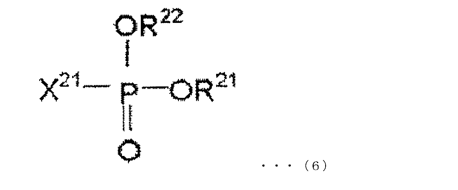
- R 21 and R 22 are each independently an alkyl group, aryl group, alkenyl group, cyano group, phenyl group, amino group, nitro group, alkoxy group, and cycloalkyl group, and these R 21 and R 22 may combine to form a cyclic structure, and X 21 represents a halogen atom.
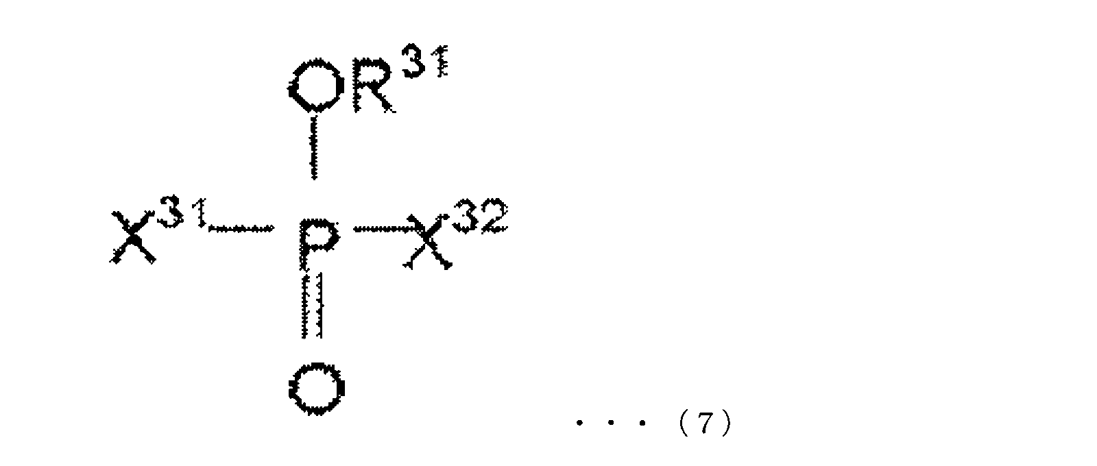
- R 31 is selected from an alkyl group, an aryl group, an alkenyl group, a cyano group, a phenyl group, an amino group, a nitro group, an alkoxy group, and a cycloalkyl group, and halogen-substituted groups thereof.
- X 31 and X 32 each independently represent a halogen atom.
- a 1 may be a substituted or unsubstituted alkylene group having 1 to 5 carbon atoms, a carbonyl group, a sulfinyl group, A branched or substituted perfluoroalkylene group having 1 to 5 carbon atoms which may be branched, a substituted or unsubstituted fluoroalkylene group having 2 to 6 carbon atoms which may be branched, or an ether bond; A substituted or unsubstituted alkylene group having 1 to 6 carbon atoms and an ether bond may be branched, and a substituted or unsubstituted perfluoroalkylene group having 1 to 6 carbon atoms or an ether bond may be branched.
- a 2 is a substituted or unsubstituted alkylene group, a substituted or unsubstituted fluoroalkylene al Shows the alkylene group or an oxygen atom.
- R 6 and R 9 each independently represents a hydrogen atom, a substituted or unsubstituted alkyl group having 1 to 5 carbon atoms, a substituted or unsubstituted alkoxy group having 1 to 5 carbon atoms, A substituted or unsubstituted fluoroalkyl group having 1 to 5 carbon atoms, a polyfluoroalkyl group having 1 to 5 carbon atoms, -SO 2 X 3 (X3 is a substituted or unsubstituted alkyl group having 1 to 5 carbon atoms),- SY 1 (Y 1 is a substituted or unsubstituted alkyl group having 1 to 5 carbon atoms), —COZ (Z is a hydrogen atom, or a substituted or unsubstituted alkyl group having 1 to 5 carbon atoms), and a halogen atom, R 7 and R 8 each independently represents a substituted or unsubstituted alkyl group having 1 to 5 carbon atoms, and
- one of the embodiments is the gel electrolyte for a lithium ion secondary battery containing 5 to 60% by mass of the phosphorus oxo acid ester derivative.
- One of the embodiments is the gel electrolyte for a lithium ion secondary battery containing 0.05 to 10% by mass of the disulfonic acid ester.
- One of the embodiments is the gel electrolyte for a lithium ion secondary battery containing 0.5 to 20% by mass of a halogenated cyclic carbonate.
- One of the embodiments is a lithium ion secondary battery including the gel electrolyte for a lithium ion secondary battery.
- FIG. 1A is a plan view of the positive electrode
- FIG. 1B is a side view of the positive electrode.
- FIG. 2A is a plan view of the negative electrode
- FIG. 2B is a side view of the negative electrode. It is a figure explaining the structure of the battery element after winding of a lithium ion secondary battery.
- the gel electrolyte for a lithium ion secondary battery of this embodiment includes a lithium salt, the copolymer as a gel component, the oxo acid ester of phosphorus, and the disulfonic acid ester.
- the copolymer includes a first monomer consisting of at least one compound selected from the compounds represented by chemical formulas (1) and (2) having a ring-opening polymerizable functional group, and a chemical formula having no ring-opening polymerizable functional group. It is formed by polymerizing the second monomer represented by (4).
- the ring-opening polymerizable functional group is represented by the chemical formula (3).
- R 1 represents H or CH 3
- R 2 represents any of the substituents represented by the following chemical formula (3).
- R 3 represents an alkyl group having 1 to 6 carbon atoms.
- R 4 represents H or CH 3
- R 5 represents —COOCH 3 , —COOC 2 H 5 , —COOC 3 H 7 , —COOC 4 H 9 , —COOCH 2 CH (CH 3 ).
- n represents an integer of 1 to 3.
- Examples of the first monomer represented by the formula (1) or (2) include (3-ethyl-3-oxetanyl) methyl methacrylate, glycidyl methacrylate, 3,4-epoxycyclohexylmethyl methacrylate, and the like. These may use only 1 type and may use 2 or more types together.
- the monomer represented by the formula (1) or (2) may be referred to as a monomer having a ring-opening polymerizable functional group.
- Examples of the second monomer represented by the chemical formula (4) include methyl acrylate, ethyl acrylate, methyl methacrylate, propyl methacrylate, methoxytriethylene glycol methacrylate, methoxydipropylene glycol acrylate, and the like.
- the monomer represented by the formula (4) may be used alone or in combination of two or more.
- the monomer represented by the formula (4) may be referred to as a monomer having no ring-opening polymerizable functional group.
- the oxo acid ester derivative of phosphorus in the present embodiment is at least one compound represented by the following chemical formulas (5) to (7).
- R 11 , R 12 and R 13 are each independently an alkyl group, aryl group, alkenyl group, cyano group, phenyl group, amino group, nitro group, alkoxy group, and cycloalkyl group. And any group selected from these halogen-substituted groups, any two or all of R 11 , R 12 and R 13 may be bonded to form a cyclic structure.
- R 21 and R 22 are each independently an alkyl group, aryl group, alkenyl group, cyano group, phenyl group, amino group, nitro group, alkoxy group, and cycloalkyl group, and these R 21 and R 22 may be bonded to form a cyclic structure, and X 21 represents a halogen atom.
- X 21 is preferably a fluorine atom.
- R 31 is selected from an alkyl group, an aryl group, an alkenyl group, a cyano group, a phenyl group, an amino group, a nitro group, an alkoxy group, and a cycloalkyl group, and halogen-substituted groups thereof.
- X 31 and X 32 each independently represent a halogen atom.
- X 31 and X 32 may be the same or different.
- X 31 and X 32 are preferably fluorine atoms.
- the phosphorus oxo acid ester derivative of this embodiment may contain one or more compounds represented by any one of formulas (5) to (7).
- Specific examples of the compound represented by the chemical formula (5) are not particularly limited thereto.
- trimethyl phosphate, triethyl phosphate, tributyl phosphate, triphenyl phosphate, dimethylethyl phosphate examples include phosphate esters such as dimethylpropyl phosphate, dimethylbutyl phosphate, diethylmethyl phosphate, dipropylmethyl phosphate, dibutylmethyl phosphate, methylethylpropyl phosphate, methylethylbutyl phosphate, and methylpropylbutyl phosphate. It is done.
- Examples of the phosphate ester having a halogen-substituted group include tri (trifluoroethyl) phosphate, methyl phosphate (ditrifluoroethyl), dimethyl phosphate (trifluoroethyl), ethyl phosphate (ditrifluoroethyl), Diethyl phosphate (trifluoroethyl), propyl phosphate (ditrifluoroethyl), dipropyl phosphate (trifluoroethyl), tri (pentafluoropropyl) phosphate, methyl phosphate (dipentafluoropropyl), dimethyl phosphate ( Pentafluoropropyl), ethyl phosphate (dipentafluoropropyl), diethyl phosphate (pentafluoropropyl), butyl phosphate (dipentafluoropropyl), dibutyl phosphate (penta
- Specific examples of the compound represented by the chemical formula (6) are not particularly limited, and examples thereof include dimethyl fluorophosphonate, diethyl fluorophosphonate, dibutyl fluorophosphonate, diphenyl fluorophosphonate, and fluorophosphone.
- Specific examples of the compound represented by the chemical formula (7) are not particularly limited, and examples thereof include, for example, methyl difluorohypophosphite, ethyl difluorohypophosphite, butyl difluorohypophosphite, difluoro Examples thereof include phenyl hypophosphite, difluorohypophosphite, trifluoroethyl difluorohypophosphite, fluoropropyl difluorohypophosphite, fluorophenyl difluorohypophosphite and the like.
- the content of phosphorus oxo acid ester derivative is preferably 5 to 60% by mass, and more preferably 10 to 40% by mass with respect to the entire gel electrolyte.
- the content of the oxo acid ester derivative of phosphorus is 5% by mass or more with respect to the gel electrolyte, the effect of suppressing the combustion of the electrolytic solution can be obtained more effectively. Increases effectiveness.
- the content of the oxo acid ester derivative of phosphorus is 60% by mass or less, the battery characteristics are improved by suppressing the increase in resistance, and the effect of suppressing the reductive decomposition by the disulfonic acid ester is more effectively obtained. This makes it easier to ensure a long-term combustion suppression effect.
- the disulfonic acid ester in the present embodiment is at least one selected from a cyclic disulfonic acid ester represented by the chemical formula (8) and a chain disulfonic acid ester represented by the chemical formula (9). Disulfonic acid esters contribute to the formation of SEI. The disulfonic acid ester is preferably included as an additive.
- a 1 may be a substituted or unsubstituted alkylene group having 1 to 5 carbon atoms, a carbonyl group, a sulfinyl group, A branched or substituted perfluoroalkylene group having 1 to 5 carbon atoms which may be branched, a substituted or unsubstituted fluoroalkylene group having 2 to 6 carbon atoms which may be branched, or an ether bond; A substituted or unsubstituted alkylene group having 1 to 6 carbon atoms and an ether bond may be branched, and a substituted or unsubstituted perfluoroalkylene group having 1 to 6 carbon atoms or an ether bond may be branched.
- .A 2 showing a good substituted or unsubstituted fluoroalkylene group having 2 to 6 carbon atoms be substituted or unsubstituted alkylene group, Furuoroa substituted or unsubstituted Shows the Killen group or an oxygen atom.
- R 6 and R 9 each independently represents a hydrogen atom, a substituted or unsubstituted alkyl group having 1 to 5 carbon atoms, a substituted or unsubstituted alkoxy group having 1 to 5 carbon atoms, A substituted or unsubstituted fluoroalkyl group having 1 to 5 carbon atoms, a polyfluoroalkyl group having 1 to 5 carbon atoms, -SO 2 X 3 (X3 is a substituted or unsubstituted alkyl group having 1 to 5 carbon atoms),- SY 1 (Y 1 is a substituted or unsubstituted alkyl group having 1 to 5 carbon atoms), —COZ (Z is a hydrogen atom, or a substituted or unsubstituted alkyl group having 1 to 5 carbon atoms), and a halogen atom, R 7 and R 8 each independently represents a substituted or unsubstituted alkyl group having 1 to 5 carbon atoms, and
- the compound represented by chemical formula (8) or chemical formula (9) can be obtained, for example, using the production method described in Japanese Patent Publication No. 5-44946.
- the content of the disulfonic acid ester is preferably 0.05 to 10% by mass and more preferably 0.1 to 5% by mass with respect to the entire gel electrolyte.
- the content of the disulfonic acid ester is 0.05% by mass or more, a sufficient SEI effect can be obtained.
- the content of the disulfonic acid ester is 10% by mass or less, the reductive decomposition of the oxo acid ester of phosphorus can be suppressed over a long period of time, and the increase in resistance can be suppressed, so that the battery characteristics can be further improved.
- the gel electrolyte of this embodiment may contain an aprotic solvent.
- An aprotic solvent may be contained in the electrolyte for a lithium ion secondary battery of the present embodiment.
- the aprotic solvent include propylene carbonate (PC), ethylene carbonate (EC), butylene carbonate (BC), cyclic carbonates such as vinylene carbonate (VC), dimethyl carbonate (DMC), diethyl carbonate (DEC), and ethyl methyl.
- Linear carbonates such as carbonate (EMC) and dipropyl carbonate (DPC), aliphatic carboxylic acid esters such as methyl formate, methyl acetate and ethyl propionate, ⁇ -lactones such as ⁇ -butyrolactone, 1,2- Chain ethers such as ethoxyethane (DEE) and ethoxymethoxyethane (EME), cyclic ethers such as tetrahydrofuran and 2-methyltetrahydrofuran, dimethyl sulfoxide, 1,3-dioxolane, formamide, acetamide, di Methylformamide, dioxolane, acetonitrile, propylnitrile, nitromethane, ethyl monoglyme, phosphoric acid triester, trimethoxymethane, dioxolane derivatives, sulfolane, methylsulfolane, 1,3-dimethyl-2-imidazolid
- the gel electrolyte of the present embodiment may further contain a cyclic carbonate containing halogen as an additive.
- a cyclic carbonate containing halogen By adding a cyclic carbonate containing halogen to the gel electrolyte, it contributes to the improvement of the ionic conductivity of the electrolyte and the formation of a film, so that the battery characteristics can be maintained for a long time and the combustion can be suppressed.
- the cyclic carbonate containing halogen include fluorine-containing carbonate.
- the fluorine-containing carbonate includes linear and cyclic ones, and is preferably a cyclic fluorine-containing carbonate (hereinafter also abbreviated as fluorine-containing cyclic carbonate).
- the content of the halogen-containing cyclic carbonate is preferably 0.5 to 20% by mass, more preferably 0.1 to 10% by mass, based on the entire gel electrolyte. It is more preferably in the range of ⁇ 8% by mass, and particularly preferably in the range of 1 to 5% by mass.
- the fluorine-containing cyclic carbonate is not particularly limited, but a compound obtained by fluorinating a part of propylene carbonate, vinylene carbonate, vinyl ethylene carbonate, or the like can also be used. More specifically, for example, 4-fluoro-1,3-dioxolane-2-one (fluoroethylene carbonate, hereinafter also referred to as FEC), (cis or trans) 4,5-difluoro-1,3-dioxolane-2 -One, 4,4-difluoro-1,3-dioxolan-2-one, 4-fluoro-5-methyl-1,3-dioxolan-2-one and the like can be used. Among these, fluoroethylene carbonate is preferable.
- Electrolyte contained in the gel electrolyte of the present embodiment is not limited to, for example, LiPF 6, LiBF 4, LiAsF 6, LiSbF 6, LiClO 4, LiAlCl 4, and LiN (C n F 2n + 1 SO 2 ) (C m F 2m + 1 SO 2 ) (n and m are natural numbers), LiCF 3 SO 3 and the like.
- the gel electrolyte of this embodiment can be obtained from, for example, the following Step A and Step B.
- Step A a step of synthesizing a copolymer of the first monomer represented by the formula (1) or (2) and the second monomer represented by the formula (4).
- Step B lithium salt, Step.
- the copolymer can be synthesized by using a radical polymerization initiator.
- radical polymerization initiators include azo initiators such as N, N-azobisisobutyronylyl, dimethyl N, N′-azobis (2-methylpropionate), benzoyl peroxide, lauroyl peroxide, and the like. An organic peroxide type initiator is mentioned. These radical polymerization initiators bind to the terminal of the copolymer of the first monomer represented by the formula (1) or (2) and the second monomer represented by the formula (4) at the start of the reaction. Therefore, the reaction is not caused again by reheating after completion of the reaction.
- the cationic polymerization initiator is not particularly limited.
- various onium salts for example, cation salts such as ammonium and phosphonium, -BF 4 , -PF 6 , -CF 3 SO 3
- anionic salts such as LiBF 4 and LiPF 6 .
- a radical polymerization initiator such as an organic peroxide is not required in the step Step B of obtaining the gel electrolyte. Therefore, phosphorus oxo acid ester derivatives and disulfonic acid esters are not decomposed in the gelation step. Further, since the radical polymerization initiator is unnecessary for the battery, the battery characteristics are not deteriorated by the influence of the residue after polymerization. Further, the gel electrolyte does not have to worry about leakage as compared with the electrolytic solution, and good adhesion characteristics between the negative electrode and the positive electrode and the separator can be obtained over a long period of time so that good life characteristics can be obtained.
- the gel electrolyte of the present embodiment can reduce the amount of gas generated during the initial charge, and is preferable from the viewpoint of safety.
- the reason for this is that the phosphorus oxo acid ester derivative and the disulfonic acid ester coexist in the gel electrolyte, resulting in a reaction mechanism different from that of SEI formation in the gel electrolyte containing only the disulfonic acid ester. It is speculated that the amount of gas generated is reduced because SEI can be formed by incorporating a part of the derivative.
- Examples of the negative electrode active material included in the negative electrode of the lithium ion secondary battery including the gel electrolyte of the present embodiment include one or two selected from the group consisting of lithium metal, a lithium alloy, and a material capable of inserting and extracting lithium.
- the above substances can be used.
- a material capable of inserting and extracting lithium ions a carbon material or an oxide can be used.
- graphite that absorbs lithium, amorphous carbon, diamond-like carbon, carbon nanotube, or a composite material thereof can be used.
- graphite has high electron conductivity, excellent adhesion to a current collector made of a metal such as copper, and voltage flatness. Since it is formed at a high processing temperature, it contains few impurities and improves negative electrode performance. This is preferable.
- a composite material of graphite with high crystallinity and amorphous carbon with low crystallinity can be used.
- any of silicon oxide, tin oxide, indium oxide, zinc oxide, lithium oxide, phosphoric acid, boric acid, or a composite thereof may be used, and it is particularly preferable to include silicon oxide.
- the structure is preferably in an amorphous state. This is because silicon oxide is stable and does not cause a reaction with other compounds, and the amorphous structure does not lead to deterioration due to nonuniformity such as crystal grain boundaries and defects.
- a film forming method a vapor deposition method, a CVD method, a sputtering method, or the like can be used.
- the lithium alloy is composed of lithium and a metal capable of forming an alloy with lithium.
- a metal capable of forming an alloy with lithium is composed of a binary or ternary alloy of a metal such as Al, Si, Pb, Sn, In, Bi, Ag, Ba, Ca, Hg, Pd, Pt, Te, Zn, La, and lithium.
- the lithium metal or lithium alloy is particularly preferably amorphous. This is because the amorphous structure hardly causes deterioration due to non-uniformity such as crystal grain boundaries and defects.
- Lithium metal or lithium alloy may be appropriately formed by a melt cooling method, a liquid quenching method, an atomizing method, a vacuum deposition method, a sputtering method, a plasma CVD method, a photo CVD method, a thermal CVD method, a sol-gel method, or the like. it can.
- Examples of the positive electrode active material included in the positive electrode of the lithium ion secondary battery including the gel electrolyte for the lithium ion secondary battery of the present embodiment include lithium-containing composite oxides such as LiCoO 2 , LiNiO 2 , and LiMn 2 O 4. Can be mentioned. In addition, the transition metal portion of these lithium-containing composite oxides may be replaced with another element.
- a lithium-containing composite oxide having a plateau at 4.5 V or more at the metal lithium counter electrode potential can be used.
- the lithium-containing composite oxide include spinel-type lithium manganese composite oxide, olivine-type lithium-containing composite oxide, and reverse spinel-type lithium-containing composite oxide.
- the lithium-containing composite oxide include Li a (MxMn 2 ⁇ x ) O 4 (where 0 ⁇ x ⁇ 2 and 0 ⁇ a ⁇ 1.2. M is Ni, And at least one selected from the group consisting of Co, Fe, Cr and Cu.).
- a laminated body or a wound body can be used as the electrode element, and an aluminum laminate exterior body or a metal exterior body can be used as the exterior body.
- the battery capacity is not limited.
- the gel electrolyte of this embodiment does not require a radical polymerization initiator such as an organic peroxide for gelation, the phosphorus oxo acid ester derivative or disulfonic acid ester is not decomposed during heat polymerization. Further, since the radical polymerization initiator is unnecessary for the battery, the battery characteristics are not deteriorated by the influence of the residue after polymerization. In addition, leakage due to the gel electrolyte can be prevented.
- a radical polymerization initiator such as an organic peroxide for gelation
- the reductive decomposition of the oxo acid ester derivative of phosphorus on the negative electrode active material can be suppressed by including a disulfonic acid ester that forms SEI having a very high reductive decomposition suppressing effect. Only in the presence of a disulfonic acid ester can an increase in resistance due to reductive decomposition of an oxo acid ester derivative of phosphorus be suppressed over a long period of time, and good lifetime characteristics can be obtained over a long period of time.
- the phosphorus oxo acid ester derivative can be suppressed by reductive decomposition over a long period of time, an effective amount of phosphorus oxo acid ester derivative can be present in the gel electrolyte even after long-term use to suppress combustibility. Therefore, high safety can be obtained over a long period of time.
- the gel electrolyte has no worry of leakage, and has good adhesion between the negative electrode and the positive electrode and the separator, so that good life characteristics can be obtained over a long period of time.
- the amount of gas generated at the first charge is reduced.
- the reaction mechanism different from the SEI formation in the non-aqueous electrolyte containing only the disulfonic acid ester due to the coexistence of the oxo acid ester derivative of phosphorus and the disulfonic acid ester in the gel electrolyte. It is presumed that the amount of gas generated is reduced because SEI in which some oxo acid ester derivatives of phosphorus are incorporated is formed.
- the SEI by the disulfonic acid ester incorporating the phosphorus oxo acid ester derivative is strong SEI. It is speculated that there is a possibility that the reductive decomposition inhibiting effect on the gel electrolyte component containing the oxo acid ester derivative of phosphorus is increased. Due to this effect, it is presumed that the life characteristics are also good. Furthermore, since reductive decomposition of phosphorus oxo acid ester derivatives can be suppressed over a long period of time, high safety can be obtained over a long period of time.
- FIG. 1 is a schematic diagram illustrating the configuration of the positive electrode of the lithium ion battery of Example 1.
- FIG. 2 is a schematic view illustrating the configuration of the negative electrode of the lithium ion battery of Example 1.
- FIG. 3 is a schematic cross-sectional view illustrating the configuration of the battery element after winding the lithium ion battery of Example 1.
- Example 1 First, the production of the positive electrode will be described with reference to FIG. A mixture of 85% by mass of LiMn 2 O 4 as a positive electrode active material, 7% by mass of acetylene black as a conductive auxiliary material, and 8% by mass of polyvinylidene fluoride as a binder was added and further mixed with N-methylpyrrolidone, A positive electrode slurry was prepared. This positive electrode slurry is applied to both surfaces of a 20 ⁇ m thick Al foil 2 as a current collector by a doctor blade method so that the thickness after the roll press treatment is 160 ⁇ m, dried at 120 ° C. for 5 minutes, and roll press treatment The process was given and the positive electrode active material application part 3 was formed.
- coated to either surface was provided in both ends. Further, a positive electrode conductive tab 6 was provided in one of the positive electrode active material non-applied portions 5. Next to the positive electrode active material non-applied portion 5 provided with the positive electrode conductive tab 6, the positive electrode active material single-side applied portion 4 in which the positive electrode active material is applied only on one surface is provided.
- the positive electrode 1 was produced by the above method.
- N-methylpyrrolidone was added to and mixed with 90% by mass of graphite as the negative electrode active material, 1% by mass of acetylene black as the conductive auxiliary agent, and 9% by mass of polyvinylidene fluoride as the binder, and the negative electrode slurry was mixed.
- This negative electrode slurry is applied to both surfaces of a 10 ⁇ m thick Cu foil 8 serving as a current collector by a doctor blade method so that the thickness after the roll press treatment is 120 ⁇ m, and dried at 120 ° C. for 5 minutes, and the roll press treatment step
- the negative electrode active material application part 9 was formed.
- coated to either surface was provided in both ends.
- one of the negative electrode active material non-applied portions 11 was provided with a negative electrode conductive tab 12.
- surface was provided next to the negative electrode active material non-application part 11 with which the negative electrode conductive tab 12 was provided.
- the negative electrode 7 was produced by the above method.
- the production of the battery element will be described with reference to FIG.
- Two separators 13 made of a polypropylene microporous membrane having a membrane thickness of 25 ⁇ m and a porosity of 55% were welded, and the cut portion was fixed to the core of the winding device and wound up. 1 (FIG. 1) and the tip of the negative electrode 7 (FIG. 2) were introduced.
- the positive electrode 1 is on the opposite side of the connection portion of the positive electrode conductive tab 6, and the negative electrode 7 is on the connection portion side of the negative electrode conductive tab 12 on the tip side.
- the negative electrode was placed between the two separators, and the positive electrode was placed on the upper surface of the separator, and the winding core was rotated and wound to form a battery element (hereinafter referred to as jelly roll (J / R)).
- jelly roll J / R
- the J / R was housed in an embossed laminate outer package, the positive electrode conductive tab 6 and the negative electrode conductive tab 12 were pulled out, one side of the laminate outer package was folded back, and heat fusion was performed leaving a portion for injection. .
- ethyl acrylate was charged as the second monomer, and (3-ethyl-3-oxetanyl) methyl methacrylate was charged at a ratio of 26 mass% as the first monomer.
- EC ethylene carbonate
- DEC diethyl carbonate
- 2500 ppm of N, N'-azobisisobutyronitrile was added with respect to the monomer weight. The reaction was heated at 65 to 70 ° C. while introducing dry nitrogen gas, and then cooled to room temperature.
- the pregel solution was injected from the laminate injection part, and impregnated with vacuum.
- the liquid injection part was heat-sealed.
- the pregel solution was heat-polymerized on condition of 60 degreeC and 24 hours, and was gelatinized. A battery was obtained through the above steps.
- the cycle test of the obtained battery was CC-CV charge (upper limit voltage 4.2V, current 1C, CV time 1.5 hours), CC discharge (lower limit voltage 3.0V, current 1C), both at 45 ° C. Carried out.
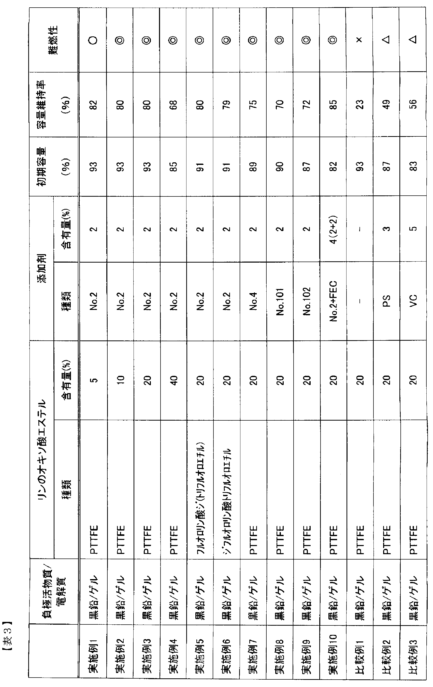
- the capacity retention rate was the ratio of the discharge capacity at the 1000th cycle to the discharge capacity at the 1st cycle. The capacity retention rate is shown in Table 3.
- the combustion test was performed by placing the battery after the cycle test 10 cm above the tip of the flame of the gas burner. And flame retardance was judged as follows from a mode that electrolyte solution volatilizes and combusts.
- the electrolyte did not ignite: ⁇ , even after ignited, extinguished after 2 to 3 seconds: ⁇ , even after ignited, extinguished within 10 seconds: ⁇ , continued to burn without extinguishing within 10 seconds: x.
- Example 2 was performed in the same manner as Example 1 except that a pregel solution was prepared by mixing 10% by mass of tri (2,2,2-trifluoroethyl) phosphate (hereinafter also referred to as PTTFE).
- PTTFE tri (2,2,2-trifluoroethyl) phosphate
- Example 3 was carried out in the same manner as in Example 1 except that 20% by mass of PTTFE was mixed to prepare a pregel solution.
- Example 4 was carried out in the same manner as Example 1 except that 40% by mass of PTTFE was mixed to prepare a pregel solution.
- Example 5 a pregel solution was prepared by mixing 20% by mass of di (2,2,2-trifluoroethyl) fluorophosphate (hereinafter also simply referred to as ditrifluoroethyl fluorophosphate) instead of PTTFE. was carried out in the same manner as in Example 1.
- di (2,2,2-trifluoroethyl) fluorophosphate hereinafter also simply referred to as ditrifluoroethyl fluorophosphate
- Example 6 Example 6 was carried out except that 20% by mass of 2,2,2-trifluoroethyl difluorophosphate (hereinafter also simply referred to as trifluoroethyl difluorophosphate) was mixed in place of PTTFE to prepare a pregel solution. Performed as in Example 1.
- 2,2,2-trifluoroethyl difluorophosphate hereinafter also simply referred to as trifluoroethyl difluorophosphate
- Example 7 is No. 1 in Table 1. No. 2 instead of No. 2 The same procedure as in Example 3 was carried out except that a pregel solution was prepared by mixing 2% by mass of the compound No. 4.
- Example 8 is No. 1 in Table 1. No. 2 in Table 2 instead of the compound of 2 The same procedure as in Example 3 was performed except that a pregel solution was prepared by mixing 2% by mass of the compound 101.
- Example 9 is No. 1 in Table 1. No. 2 in Table 2 instead of the compound of 2 The same procedure as in Example 3 was performed except that a pregel solution was prepared by mixing 2% by mass of the compound No. 102.
- Example 10 was carried out in the same manner as Example 3 except that a pregel solution was prepared by further mixing 2% by mass of fluoroethylene carbonate (FEC).
- FEC fluoroethylene carbonate
- Comparative Example 1 Comparative Example 1 is No. 1 in Table 1. The same procedure as in Example 3 was performed except that the pregel solution was prepared without mixing the compound of 2.
- Comparative Example 2 is No. 1 in Table 1.
- the same procedure as in Example 3 was performed, except that the pregel solution was prepared by mixing 3% by mass of 1,3-propane sultone (PS) without mixing the compound of 2.
- PS 1,3-propane sultone
- Comparative Example 3 is No. 1 in Table 1. The same procedure as in Example 3 was performed, except that the pregel solution was prepared by mixing 5% by mass of vinylene carbonate (VC) without mixing the compound of No. 2.
- VC vinylene carbonate
- Table 3 shows the results of Examples 1 to 10 and Comparative Examples 1 to 3.
- Examples 1 to 4 when the phosphate ester content increases, the capacity retention rate after 1000 cycles tends to slightly decrease, but the flame resistance of the battery electrolyte after evaluation is very high. It was good. Further, when Examples 3 and 5 to 10 containing the same amount of phosphate ester were compared with Comparative Examples 1 to 3, Examples 3 and 5 to 10 to which disulfonate was added had a good capacity retention rate. The flame retardancy was also very good. Furthermore, in Example 10 to which FEC was added, the capacity retention rate was good and the flame retardancy was also very good.
- Example 11 was performed in the same manner as Example 3 except that the negative electrode material of Example 3 was replaced with a silicon-based material instead of graphite.
- a method for manufacturing the negative electrode will be described below. First, 90% by mass of silicon, 1% by mass of acetylene black as a conductive auxiliary agent, and 9% by mass of a polyimide binder as a binder were mixed, N-methylpyrrolidone was added and further mixed to prepare a negative electrode slurry. .
- This negative electrode slurry was applied to both sides of a 10 ⁇ m thick Cu foil serving as a current collector, and was applied so that the thickness after the roll press treatment was 80 ⁇ m. And it was made to dry at 120 degreeC for 5 minutes, the press process was performed, and also it was made to dry additionally at 300 degreeC for 10 minutes, and the negative electrode active material application part 9 was formed.
- Example 12 In Example 12, No. 1 in Table 1 was obtained. No. 2 in Table 2 instead of the compound of 2 The same procedure as in Example 11 was performed, except that a pregel solution was prepared by mixing 2% by mass of the compound 101.
- Comparative Example 4 is No. 1 in Table 1. The same procedure as in Example 11 was performed, except that the pregel solution was prepared by mixing 3% by mass of PS without mixing the compound of 2.
- Comparative Example 5 is No. 1 in Table 1.
- the same procedure as in Example 11 was performed except that the pregel solution was prepared by mixing 5% by mass of VC without mixing the compound of 2.
- Table 4 shows the results of Examples 12 and 13 and Comparative Examples 4 and 5.
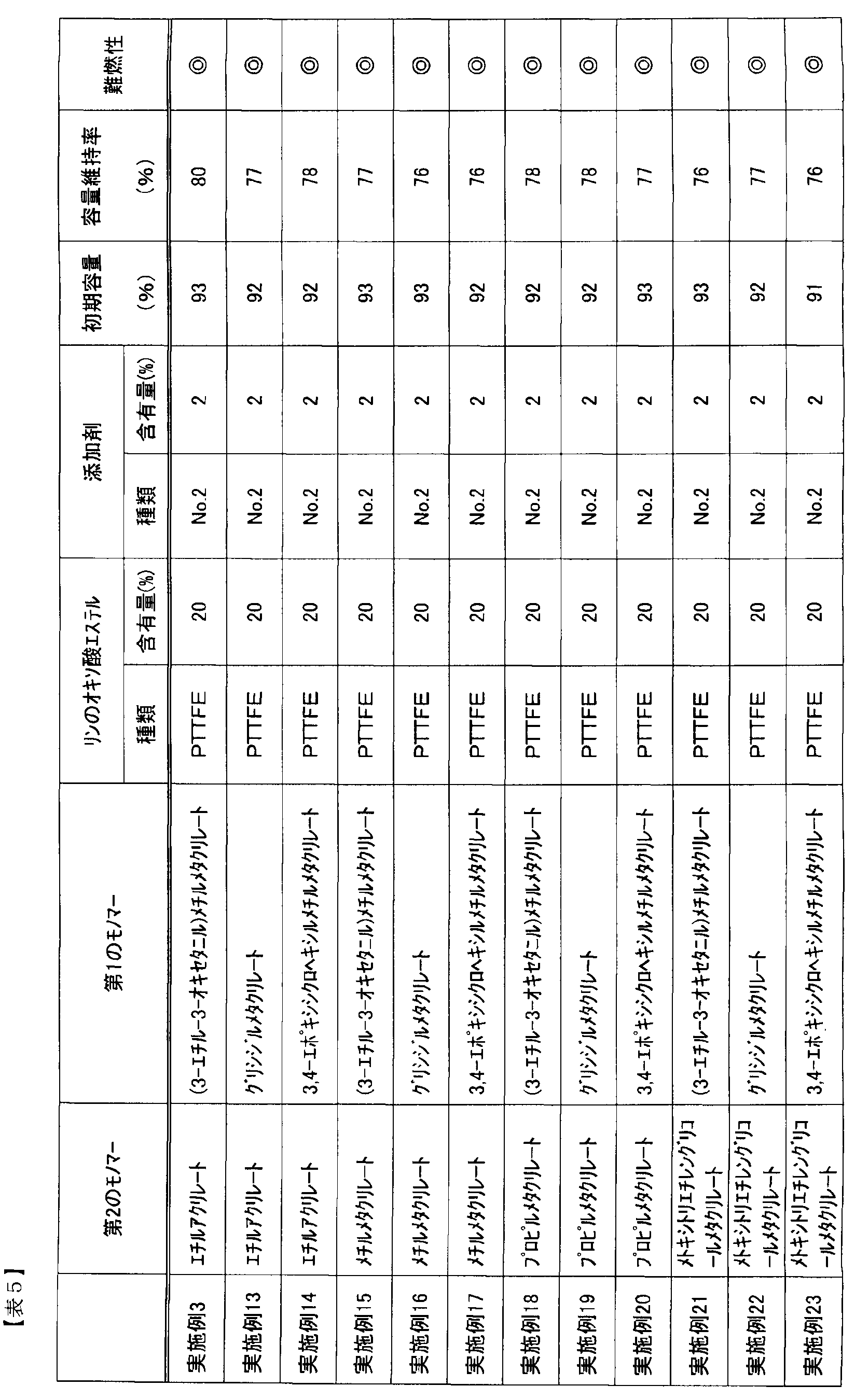
- Example 13 was performed in the same manner as Example 3 except that ethyl acrylate was used as the second monomer and glycidyl methacrylate was used as the first monomer.
- Example 14 was performed in the same manner as Example 3 except that ethyl acrylate was used as the second monomer and 3,4-epoxycyclohexylmethyl methacrylate was used as the first monomer.
- Example 15 was carried out in the same manner as Example 3 except that methyl methacrylate was used as the second monomer and (3-ethyl-3-oxetanyl) methyl methacrylate was used as the first monomer.
- Example 16 was performed in the same manner as in Example 3 except that methyl methacrylate was used as the second monomer and glycidyl methacrylate was used as the first monomer.
- Example 17 was carried out in the same manner as Example 3 except that methyl methacrylate was used as the second monomer and 3,4-epoxycyclohexylmethyl methacrylate was used as the first monomer.
- Example 18 was carried out in the same manner as Example 3 except that propyl methacrylate was used as the second monomer and (3-ethyl-3-oxetanyl) methyl methacrylate was used as the first monomer.
- Example 19 was performed in the same manner as in Example 3 except that propyl methacrylate was used as the second monomer and glycidyl methacrylate was used as the first monomer.
- Example 20 Example 20 was performed in the same manner as Example 3 except that propyl methacrylate was used as the second monomer and 3,4-epoxycyclohexylmethyl methacrylate was used as the first monomer.
- Example 21 was carried out in the same manner as in Example 3 except that methoxytriethylene glycol methacrylate was used as the second monomer and (3-ethyl-3-oxetanyl) methyl methacrylate was used as the first monomer.
- Example 22 was carried out in the same manner as Example 3 except that methoxytriethylene glycol methacrylate was used as the second monomer and glycidyl methacrylate was used as the first monomer.
- Example 23 was carried out in the same manner as Example 3 except that methoxytriethylene glycol methacrylate was used as the second monomer and 3,4-epoxycyclohexylmethyl methacrylate was used as the first monomer.
- SEI by disulfonic acid ester can suppress the reductive decomposition of phosphorus oxo acid ester over a long period of time regardless of the polymer structure, and can obtain good life characteristics, and as a result, it is high over a long period of time. I was able to get safety.
- Comparative Example 6 Comparative Example 6 was performed in the same manner as Example 1 except that the gel electrolyte of Example 1 was produced as follows.
- Example 1 the pregel solution was injected from the injection part and impregnated with vacuum.
- the pregel solution was polymerized and gelled at 80 ° C. for 2 hours.
- a battery was obtained through the above steps and measured in the same manner as in Example 1.
- Comparative Example 7 was performed in the same manner as Comparative Example 6 except that 10% by mass of PTTFE was mixed.
- Comparative Example 8 Comparative Example 8 was performed in the same manner as Comparative Example 6 except that 20% by mass of PTTFE was mixed.
- Table 6 shows the results of Examples 1 to 3 and Comparative Examples 6 to 8.
- Comparative Examples 6 to 8 show that the combustion suppression effect after the cycle is lowered even with the same amount of phosphate ester added.
- the flame retardancy is lowered by the decomposition of the phosphate ester by the polymerization initiator in the gel electrolyte.
- the cycle maintenance rate is lowered because SEI was hardly formed normally by the decomposition of the phosphate ester by the polymerization initiator.
- the battery containing the gel electrolyte of the present embodiment can suppress the reductive decomposition of phosphorus oxoacid ester over a long period of time, and can obtain good life characteristics. As a result, high safety over a long period of time. Can get.
- This embodiment can be used for other energy storage devices such as electric double layer capacitors and lithium ion capacitors.
- Positive electrode 2 Al foil 3: Positive electrode active material application part 4: Positive electrode active material single-side application part 5: Positive electrode active material non-application part 6: Positive electrode conductive tab 7: Negative electrode 8: Cu foil 9: Negative electrode active material application part 10 : Negative electrode active material one side application part 11: Negative electrode active material non-application part 12: Negative electrode conductive tab 13: Insulating porous sheet 14: Positive electrode active material layer 15: Negative electrode active material layer
Abstract
Description
リチウム塩と、
化学式(1)及び(2)で示される化合物から選ばれる少なくとも1種からなる第1のモノマーと化学式(4)で示される第2のモノマーとの共重合体と、
化学式(5)乃至(7)で示される化合物から選ばれる少なくとも1種からなるリンのオキソ酸エステル誘導体と、
化学式(8)で示される環状ジスルホン酸エステル及び化学式(9)で示される鎖状ジスルホン酸エステルから選ばれる少なくとも1種からなるジスルホン酸エステルと、
を含有するリチウムイオン二次電池用ゲル電解質である。


、及び-NY2CONY3Y4(Y2~Y4は、それぞれ独立して、水素原子、または置換もしくは無置換の炭素数1~5のアルキル基)、から選ばれる原子または基を示す。)


先ず、図1を参照して正極の作製について説明する。正極活物質としてLiMn2O4を85質量%、導電補助材としてアセチレンブラックを7質量%、バインダーとしてポリフッ化ビニリデンを8質量%として混合したものに、N-メチルピロリドンを加えてさらに混合し、正極スラリーを作製した。この正極スラリーをドクターブレード法により集電体となる厚さ20μmのAl箔2の両面にロールプレス処理後の厚さが160μmになるように塗布し、120℃で5分乾燥させ、ロールプレス処理工程を施し、正極活物質塗布部3を形成した。なお、両端部にはいずれの面にも正極活物質が塗布されていない正極活物質非塗布部5を設けた。また、そのうち一方の正極活物質非塗布部5には正極導電タブ6を設けた。正極導電タブ6が設けられた正極活物質非塗布部5の隣に、片面のみ正極活物質を塗布した正極活物質片面塗布部4を設けた。以上の方法により正極1を作製した。
実施例2は、リン酸トリ(2,2,2-トリフルオロエチル)(以下、PTTFEとも称す)を10質量%混合してプレゲル溶液を調製した以外は、実施例1と同様に行った。
実施例3は、PTTFEを20質量%混合してプレゲル溶液を調製した以外は、実施例1と同様に行った。
実施例4は、PTTFEを40質量%混合してプレゲル溶液を調製した以外は、実施例1と同様に行った。
実施例5は、PTTFEの代わりにフルオロリン酸ジ(2,2,2-トリフルオロエチル)(以下、単にフルオロリン酸ジトリフルオロエチルとも称す)を20質量%混合してプレゲル溶液を調製した以外は、実施例1と同様に行った。
実施例6は、PTTFEの代わりにジフルオロリン酸2,2,2-トリフルオロエチル(以下、単にジフルオロリン酸トリフルオロエチルとも称す)を20質量%混合してプレゲル溶液を調製した以外は、実施例1と同様に行った。
実施例7は、表1のNo.2の化合物の代わりにNo.4の化合物を2質量%混合してプレゲル溶液を調製した以外は、実施例3と同様に行った。
実施例8は、表1のNo.2の化合物の代わりに表2のNo.101の化合物を2質量%混合してプレゲル溶液を調製した以外は、実施例3と同様に行った。
実施例9は、表1のNo.2の化合物の代わりに表2のNo.102の化合物を2質量%混合してプレゲル溶液を調製した以外は、実施例3と同様に行った。
実施例10は、さらにフルオロエチレンカーボネート(FEC)を2質量%混合してプレゲル溶液を調製した以外は、実施例3と同様に行った。
比較例1は、表1のNo.2の化合物を混合しないでプレゲル溶液を調製した以外は、実施例3と同様に行った。
比較例2は、表1のNo.2の化合物を混合せず、1,3-プロパンスルトン(PS)を3質量%混合してプレゲル溶液を調製した以外は、実施例3と同様に行った。
比較例3は、表1のNo.2の化合物を混合せず、ビニレンカーボネート(VC)を5質量%混合してプレゲル溶液を調製した以外は、実施例3と同様に行った。
実施例11は、実施例3の負極材料を黒鉛の代わりにシリコン系材料を用いた以外は、実施例3と同様に行った。以下に負極の作製方法について説明する。まず、シリコンを90質量%、導電補助剤としてアセチレンブラックを1質量%、バインダーとしてポリイミドバインダを9質量%となるように混合し、N-メチルピロリドンを加えてさらに混合して負極スラリーを作製した。この負極スラリーを集電体となる厚さ10μmのCu箔両面に塗布し、ロールプレス処理後の厚さが80μmとなるように塗布した。そして、120℃で5分乾燥させ、プレス工程を施し、さらに300℃で10分の追加的に乾燥させ、負極活物質塗布部9を形成した。
実施例12は、表1のNo.2の化合物の代わりに表2のNo.101の化合物を2質量%混合してプレゲル溶液を調製した以外は、実施例11と同様に行った。
比較例4は、表1のNo.2の化合物を混合せず、PSを3質量%混合してプレゲル溶液を調製した以外は、実施例11と同様に行った。
比較例5は、表1のNo.2の化合物を混合せず、VCを5質量%混合してプレゲル溶液を調製した以外は、実施例11と同様に行った。

実施例13は、第2のモノマーとしてエチルアクリレート、第1のモノマーとしてグリシジルメタクリレートを用いた以外は、実施例3と同様に行った。
実施例14は、第2のモノマーとしてエチルアクリレート、第1のモノマーとして3,4-エポキシシクロヘキシルメチルメタクリレートを用いた以外は、実施例3と同様に行った。
実施例15は、第2のモノマーとしてメチルメタクリレート、第1のモノマーとして(3-エチル-3-オキセタニル)メチルメタクリレートを用いた以外は、実施例3と同様に行った。
実施例16は、第2のモノマーとしてメチルメタクリレート、第1のモノマーとしてグリシジルメタクリレートを用いた以外は、実施例3と同様に行った。
実施例17は、第2のモノマーとしてメチルメタクリレート、第1のモノマーとして3,4-エポキシシクロヘキシルメチルメタクリレートを用いた以外は、実施例3と同様に行った。
実施例18は、第2のモノマーとしてプロピルメタクリレート、第1のモノマーとして(3-エチル-3-オキセタニル)メチルメタクリレートを用いた以外は、実施例3と同様に行った。
実施例19は、第2のモノマーとしてプロピルメタクリレート、第1のモノマーとしてグリシジルメタクリレートを用いた以外は、実施例3と同様に行った。
実施例20は、第2のモノマーとしてプロピルメタクリレート、第1のモノマーとして3,4-エポキシシクロヘキシルメチルメタクリレートを用いた以外は、実施例3と同様に行った。
実施例21は、第2のモノマーとしてメトキシトリエチレングリコールメタクリレート、第1のモノマーとして(3-エチル-3-オキセタニル)メチルメタクリレートを用いた以外は、実施例3と同様に行った。
実施例22は、第2のモノマーとしてメトキシトリエチレングリコールメタクリレート、第1のモノマーとしてグリシジルメタクリレートを用いた以外は、実施例3と同様に行った。
実施例23は、第2のモノマーとしてメトキシトリエチレングリコールメタクリレート、第1のモノマーとして3,4-エポキシシクロヘキシルメチルメタクリレートを用いた以外は、実施例3と同様に行った。
比較例6は、実施例1のゲル電解質を以下のように作製した以外は実施例1と同様に行った。
比較例7は、PTTFEを10質量%混合した以外は比較例6と同様に行った。
比較例8は、PTTFEを20質量%混合した以外は比較例6と同様に行った。

2:Al箔
3:正極活物質塗布部
4:正極活物質片面塗布部
5:正極活物質非塗布部
6:正極導電タブ
7:負極
8:Cu箔
9:負極活物質塗布部
10:負極活物質片面塗布部
11:負極活物質非塗布部
12:負極導電タブ
13:絶縁性多孔質シート
14:正極活物質層
15:負極活物質層
Claims (5)
- リチウム塩と、
化学式(1)及び(2)で示される化合物から選ばれる少なくとも1種からなる第1のモノマーと化学式(4)で示される第2のモノマーとの共重合体と、
化学式(5)乃至(7)で示される化合物から選ばれる少なくとも1種からなるリンのオキソ酸エステル誘導体と、
化学式(8)で示される環状ジスルホン酸エステル及び化学式(9)で示される鎖状ジスルホン酸エステルから選ばれる少なくとも1種からなるジスルホン酸エステルと、
を含有するリチウムイオン二次電池用ゲル電解質。


- 前記リンのオキソ酸エステル誘導体を、5~60質量%含有する請求項1に記載のリチウムイオン二次電池用ゲル電解質。
- 前記ジスルホン酸エステルを、0.05~10質量%含有する請求項1または2に記載のリチウムイオン二次電池用ゲル電解質。
- さらに、ハロゲンを含有する環状炭酸エステルを、0.5~20質量%含有する請求項1乃至3のいずれかに記載のリチウムイオン二次電池用ゲル電解質。
- 請求項1乃至4のいずれかに記載のリチウムイオン二次電池用ゲル電解質を備えたリチウムイオン二次電池。
Priority Applications (4)
| Application Number | Priority Date | Filing Date | Title |
|---|---|---|---|
| EP11853432.0A EP2660921B1 (en) | 2010-12-27 | 2011-12-22 | Gel electrolyte for lithium ion secondary batteries, and lithium ion secondary battery |
| US13/883,953 US9196926B2 (en) | 2010-12-27 | 2011-12-22 | Gel electrolyte for lithium ion secondary battery, and lithium ion secondary battery |
| JP2012550899A JP5975523B2 (ja) | 2010-12-27 | 2011-12-22 | リチウムイオン二次電池用ゲル電解質およびリチウムイオン二次電池 |
| CN201180062840.5A CN103270640B (zh) | 2010-12-27 | 2011-12-22 | 锂离子二次电池用的凝胶电解质和锂离子二次电池 |
Applications Claiming Priority (2)
| Application Number | Priority Date | Filing Date | Title |
|---|---|---|---|
| JP2010290545 | 2010-12-27 | ||
| JP2010-290545 | 2010-12-27 |
Publications (1)
| Publication Number | Publication Date |
|---|---|
| WO2012090855A1 true WO2012090855A1 (ja) | 2012-07-05 |
Family
ID=46382961
Family Applications (1)
| Application Number | Title | Priority Date | Filing Date |
|---|---|---|---|
| PCT/JP2011/079795 WO2012090855A1 (ja) | 2010-12-27 | 2011-12-22 | リチウムイオン二次電池用ゲル電解質およびリチウムイオン二次電池 |
Country Status (5)
| Country | Link |
|---|---|
| US (1) | US9196926B2 (ja) |
| EP (1) | EP2660921B1 (ja) |
| JP (1) | JP5975523B2 (ja) |
| CN (1) | CN103270640B (ja) |
| WO (1) | WO2012090855A1 (ja) |
Cited By (2)
| Publication number | Priority date | Publication date | Assignee | Title |
|---|---|---|---|---|
| US10038217B2 (en) | 2014-04-18 | 2018-07-31 | Seeo, Inc. | Polymer composition with electrophilic groups for stabilization of lithium sulfur batteries |
| US10044064B2 (en) | 2014-04-18 | 2018-08-07 | Seeo, Inc. | Long cycle-life lithium sulfur solid state electrochemical cell |
Families Citing this family (9)
| Publication number | Priority date | Publication date | Assignee | Title |
|---|---|---|---|---|
| CN103618110B (zh) * | 2013-12-12 | 2015-12-02 | 宁德新能源科技有限公司 | 锂离子二次电池及其电解液 |
| CN103772607B (zh) * | 2014-01-26 | 2016-01-13 | 郑州大学 | 含磷交联凝胶聚合物电解质及其现场热聚合制备方法、应用 |
| EP3353844B1 (en) | 2015-03-27 | 2022-05-11 | Mason K. Harrup | All-inorganic solvents for electrolytes |
| CN106558731B (zh) * | 2015-09-28 | 2019-05-17 | 比亚迪股份有限公司 | 一种锂离子电池电解液和锂离子电池 |
| US10868332B2 (en) | 2016-04-01 | 2020-12-15 | NOHMs Technologies, Inc. | Modified ionic liquids containing phosphorus |
| US10707531B1 (en) | 2016-09-27 | 2020-07-07 | New Dominion Enterprises Inc. | All-inorganic solvents for electrolytes |
| CN108075187B (zh) * | 2016-11-10 | 2020-09-11 | 宁德时代新能源科技股份有限公司 | 电解液及二次电池 |
| EP4087005A1 (en) | 2017-07-17 | 2022-11-09 | Nohms Technologies, Inc. | Phosphorus-containing electrolytes |
| CN110247111B (zh) * | 2019-06-24 | 2022-03-29 | 中国科学院青岛生物能源与过程研究所 | 一种含磺酸或磷酸衍生物结构的固态聚合物电解质及其在二次锂电池中的应用 |
Citations (4)
| Publication number | Priority date | Publication date | Assignee | Title |
|---|---|---|---|---|
| JP2003238821A (ja) * | 2002-02-21 | 2003-08-27 | Sunstar Eng Inc | ポリマー固体電解質用難燃性組成物 |
| JP2008071559A (ja) * | 2006-09-13 | 2008-03-27 | Nec Tokin Corp | リチウムイオン二次電池 |
| JP2009277397A (ja) * | 2008-05-13 | 2009-11-26 | Hitachi Maxell Ltd | ラミネート形非水二次電池 |
| WO2011099580A1 (ja) * | 2010-02-10 | 2011-08-18 | Necエナジーデバイス株式会社 | 非水系電解液およびそれを備えるリチウムイオン二次電池 |
Family Cites Families (23)
| Publication number | Priority date | Publication date | Assignee | Title |
|---|---|---|---|---|
| JP2908719B2 (ja) | 1994-03-19 | 1999-06-21 | 日立マクセル株式会社 | 有機電解液二次電池 |
| JP3821495B2 (ja) | 1994-09-16 | 2006-09-13 | 三井化学株式会社 | 非水電解液および非水電解液電池 |
| JP3425493B2 (ja) | 1994-07-28 | 2003-07-14 | 日立マクセル株式会社 | 非水二次電池およびその製造方法 |
| JP3961597B2 (ja) | 1996-11-22 | 2007-08-22 | 三井化学株式会社 | 非水電解液及び非水電解液二次電池 |
| JPH10255839A (ja) | 1997-03-12 | 1998-09-25 | Matsushita Electric Ind Co Ltd | 非水電解質二次電池 |
| JP2001093574A (ja) * | 1999-09-22 | 2001-04-06 | Sanyo Electric Co Ltd | ゲル状高分子電解質二次電池 |
| JP4911813B2 (ja) | 2000-10-03 | 2012-04-04 | サンスター技研株式会社 | 固体電解質用架橋性組成物、ポリマー固体電解質リチウムイオン2次電池及びポリマー固体電解質リチウムイオン2次電池の製造法 |
| JP3422769B2 (ja) | 2000-11-01 | 2003-06-30 | 松下電器産業株式会社 | 非水系電池用電解液およびこれを用いた二次電池 |
| JP4662533B2 (ja) * | 2003-08-26 | 2011-03-30 | 日東電工株式会社 | 電池用セパレータのための反応性ポリマー担持多孔質フィルムとそれを用いる電池の製造方法 |
| JP2006286277A (ja) | 2005-03-31 | 2006-10-19 | Bridgestone Corp | 電池用非水電解液及びそれを備えた非水電解液二次電池 |
| JP2007059192A (ja) | 2005-08-24 | 2007-03-08 | Gs Yuasa Corporation:Kk | 非水電解液二次電池及びその製造方法 |
| JP4940625B2 (ja) * | 2005-10-21 | 2012-05-30 | ソニー株式会社 | 電解液および電池 |
| JP2007273445A (ja) * | 2006-03-09 | 2007-10-18 | Nec Tokin Corp | ポリマーゲル電解質およびそれを用いたポリマー二次電池 |
| CN101033323A (zh) | 2006-03-09 | 2007-09-12 | Nec东金株式会社 | 聚合物凝胶电解质和使用该电解质的聚合物二次电池 |
| JP2007258067A (ja) | 2006-03-24 | 2007-10-04 | Gs Yuasa Corporation:Kk | 非水電解質電池 |
| JP2008021560A (ja) | 2006-07-13 | 2008-01-31 | Daikin Ind Ltd | 非水系電解液 |
| JP2008041296A (ja) * | 2006-08-02 | 2008-02-21 | Bridgestone Corp | 電池用非水電解液及びそれを備えた非水電解液電池 |
| JP2008282735A (ja) * | 2007-05-11 | 2008-11-20 | Matsushita Electric Ind Co Ltd | 非水電解質二次電池及びその製造方法 |
| JP5260075B2 (ja) * | 2008-02-13 | 2013-08-14 | 日東電工株式会社 | 電池用セパレータ用反応性ポリマー担持多孔質フィルムとそれより得られる電極/セパレータ接合体 |
| JP5169400B2 (ja) | 2008-04-07 | 2013-03-27 | Necエナジーデバイス株式会社 | 非水電解液およびそれを用いた非水電解液二次電池 |
| JP5235109B2 (ja) * | 2008-07-15 | 2013-07-10 | 日立マクセル株式会社 | 非水電解質電池用セパレータおよび非水電解質電池 |
| JP2010062113A (ja) * | 2008-09-08 | 2010-03-18 | Nec Tokin Corp | リチウムイオン二次電池 |
| JP5721179B2 (ja) * | 2009-11-13 | 2015-05-20 | Necエナジーデバイス株式会社 | リチウムイオン二次電池用ゲル電解質およびそれを備えたリチウムイオン二次電池 |
-
2011
- 2011-12-22 US US13/883,953 patent/US9196926B2/en active Active
- 2011-12-22 JP JP2012550899A patent/JP5975523B2/ja active Active
- 2011-12-22 WO PCT/JP2011/079795 patent/WO2012090855A1/ja active Application Filing
- 2011-12-22 EP EP11853432.0A patent/EP2660921B1/en active Active
- 2011-12-22 CN CN201180062840.5A patent/CN103270640B/zh active Active
Patent Citations (4)
| Publication number | Priority date | Publication date | Assignee | Title |
|---|---|---|---|---|
| JP2003238821A (ja) * | 2002-02-21 | 2003-08-27 | Sunstar Eng Inc | ポリマー固体電解質用難燃性組成物 |
| JP2008071559A (ja) * | 2006-09-13 | 2008-03-27 | Nec Tokin Corp | リチウムイオン二次電池 |
| JP2009277397A (ja) * | 2008-05-13 | 2009-11-26 | Hitachi Maxell Ltd | ラミネート形非水二次電池 |
| WO2011099580A1 (ja) * | 2010-02-10 | 2011-08-18 | Necエナジーデバイス株式会社 | 非水系電解液およびそれを備えるリチウムイオン二次電池 |
Non-Patent Citations (1)
| Title |
|---|
| See also references of EP2660921A4 * |
Cited By (6)
| Publication number | Priority date | Publication date | Assignee | Title |
|---|---|---|---|---|
| US10038217B2 (en) | 2014-04-18 | 2018-07-31 | Seeo, Inc. | Polymer composition with electrophilic groups for stabilization of lithium sulfur batteries |
| US10044065B2 (en) | 2014-04-18 | 2018-08-07 | Seeo, Inc. | Polymer composition with electrophilic groups for stabilization of lithium sulfur batteries |
| US10044064B2 (en) | 2014-04-18 | 2018-08-07 | Seeo, Inc. | Long cycle-life lithium sulfur solid state electrochemical cell |
| US10141604B2 (en) * | 2014-04-18 | 2018-11-27 | Seeo, Inc. | Polymer composition with electrophilic groups for stabilization of lithium sulfur batteries |
| US10153514B2 (en) | 2014-04-18 | 2018-12-11 | Seeo, Inc. | Polymer composition with electrophilic groups for stabilization of lithium sulfur batteries |
| US10665895B2 (en) | 2014-04-18 | 2020-05-26 | Seeo, Inc. | Polymer composition with olefinic groups for stabilization of lithium sulfur batteries |
Also Published As
| Publication number | Publication date |
|---|---|
| EP2660921A4 (en) | 2015-12-09 |
| EP2660921A1 (en) | 2013-11-06 |
| CN103270640A (zh) | 2013-08-28 |
| JPWO2012090855A1 (ja) | 2014-06-05 |
| US9196926B2 (en) | 2015-11-24 |
| CN103270640B (zh) | 2016-08-10 |
| US20130230779A1 (en) | 2013-09-05 |
| JP5975523B2 (ja) | 2016-08-23 |
| EP2660921B1 (en) | 2016-10-19 |
Similar Documents
| Publication | Publication Date | Title |
|---|---|---|
| JP5645287B2 (ja) | 非水系電解液およびそれを備えるリチウムイオン二次電池 | |
| JP5975523B2 (ja) | リチウムイオン二次電池用ゲル電解質およびリチウムイオン二次電池 | |
| JP5721179B2 (ja) | リチウムイオン二次電池用ゲル電解質およびそれを備えたリチウムイオン二次電池 | |
| JP5403710B2 (ja) | 非水系電解液およびそれを備えたデバイス | |
| JP5315674B2 (ja) | 非水電池用電解液及びこれを用いた非水電池 | |
| JP5429845B2 (ja) | 非水電解液、ゲル電解質及びそれらを用いた二次電池 | |
| JP5738011B2 (ja) | 二次電池の非水電解液用添加剤、二次電池用非水電解液及び非水電解液二次電池 | |
| JP2008300126A (ja) | 電池用非水電解液及びそれを備えた非水電解液2次電池 | |
| JP2005514750A (ja) | 電解質系及びそれを用いたエネルギー貯蔵装置 | |
| JP5641593B2 (ja) | リチウムイオン電池 | |
| JP6476611B2 (ja) | 非水電解液電池用電解液、及びこれを用いた非水電解液電池 | |
| JP2006179458A (ja) | 電池用非水電解液及びそれを備えた非水電解液電池 | |
| CN110495042B (zh) | 锂离子二次电池用电解液、锂离子二次电池和组件 | |
| JP5435644B2 (ja) | ポリマー電解質及びそれを用いた二次電池 |
Legal Events
| Date | Code | Title | Description |
|---|---|---|---|
| 121 | Ep: the epo has been informed by wipo that ep was designated in this application |
Ref document number: 11853432 Country of ref document: EP Kind code of ref document: A1 |
|
| REEP | Request for entry into the european phase |
Ref document number: 2011853432 Country of ref document: EP |
|
| WWE | Wipo information: entry into national phase |
Ref document number: 2011853432 Country of ref document: EP |
|
| WWE | Wipo information: entry into national phase |
Ref document number: 13883953 Country of ref document: US |
|
| ENP | Entry into the national phase |
Ref document number: 2012550899 Country of ref document: JP Kind code of ref document: A |
|
| NENP | Non-entry into the national phase |
Ref country code: DE |