WO2012086502A1 - Dispositif de commande de la force de réaction de braquage pour une direction à commande électrique - Google Patents
Dispositif de commande de la force de réaction de braquage pour une direction à commande électrique Download PDFInfo
- Publication number
- WO2012086502A1 WO2012086502A1 PCT/JP2011/078993 JP2011078993W WO2012086502A1 WO 2012086502 A1 WO2012086502 A1 WO 2012086502A1 JP 2011078993 W JP2011078993 W JP 2011078993W WO 2012086502 A1 WO2012086502 A1 WO 2012086502A1
- Authority
- WO
- WIPO (PCT)
- Prior art keywords
- steering
- reaction force
- steering reaction
- input
- reverse
- Prior art date
Links
Images


Classifications
-
- B—PERFORMING OPERATIONS; TRANSPORTING
- B62—LAND VEHICLES FOR TRAVELLING OTHERWISE THAN ON RAILS
- B62D—MOTOR VEHICLES; TRAILERS
- B62D6/00—Arrangements for automatically controlling steering depending on driving conditions sensed and responded to, e.g. control circuits
- B62D6/008—Control of feed-back to the steering input member, e.g. simulating road feel in steer-by-wire applications
Definitions
- the present invention relates to a steer-by-wire type steering apparatus that is steered by a steering wheel that is not mechanically connected to a shaft between tie rods for steering, and more particularly, a steering reaction force that controls a steering reaction force applied to the steering wheel.
- the present invention relates to a force control device.
- the steering reaction force acting on the steering mechanism is detected by the steering reaction force sensor, or the steering reaction force is controlled using the control amount of the steering motor and the steering displacement amount.
- a method for estimating a force and generating a steering reaction force according to a steering reaction force is known (for example, Patent Document 1). Further, in order to improve the steering feeling, friction and viscosity components are added to the steering reaction force (Patent Documents 2 to 4).
- the frictional force in the mechanism is directly felt as a steering reaction force.
- the steer-by-wire has a problem that the friction in the mechanism portion is small and the initial steering reaction force is less responsive when the handle starts to be turned from the neutral position.
- the steer-by-wire when trying to generate a frictional force by control, since it is a non-linear element whose sign is inverted depending on the steering direction, it is difficult to reproduce a steering reaction force that is always stable and has no sense of incongruity.
- Patent Document 2 mechanical friction is applied to the steering wheel.
- an offset occurs in the return position when the hand is released, and the vehicle may flow in a single direction.
- Patent Document 3 the gain of the steering reaction force is increased in a region where the steering angle is small.
- this method tends to generate vibrations around the neutral position.
- Patent Document 4 in order to prevent an offset of the return position at the time of releasing, by multiplying the provisional target friction reaction force by the larger one of the first coefficient based on the steering angle and the second coefficient based on the steering angular velocity, The target friction reaction force is set to zero when the hand is released in the neutral position. However, the steering reaction force at the start of cutting from the neutral position is less responsive.
- the present invention has been made to solve the above-described problems, and ensures a good response when the steering wheel starts to be turned from the neutral position, prevents vibration around the neutral position, and returns to the return position when released.
- the goal is to make the position as neutral as possible.
- the steer-by-wire steering reaction force control device includes a steering angle sensor 5 that detects a steering angle with respect to a steering wheel 3 that is not mechanically connected to the steering tie rod shaft 2, and a steering reaction force.
- a steering reaction force motor 4 is provided, and based on the steering angle detected by the steering angle sensor 5, a command signal for the turning angle is combined with a driving state detection signal from another sensor 15 mounted on the vehicle.
- a steer-by-wire steering device having a steering control means 12 for controlling the steering motor 7 of the steering mechanism 6 that generates and drives the shaft 2 between the tie rods when the steering direction and the direction of the steering reaction force are different.
- the steering reaction force control unit 14 determines whether the input to the steering mechanism 6 is normal or reverse based on the steering direction and the direction of the steering reaction force.
- the steering reaction force of the steering reaction force motor 74 is controlled in accordance with the normal / reverse direction. For example, when the transmission efficiency between the forward input and the reverse input of the steering mechanism 6 is different, the steering reaction force is accurately estimated by changing the coefficient used for the steering reaction force estimation between the normal input and the reverse input. be able to.
- steering reaction force detection means 18, 18A for detecting a steering reaction force acting on the steering mechanism 6, and a steering direction detection means 19 for detecting a steering direction, and the steering reaction force control section.
- 14 is detected by a steering reaction force target value calculation unit 17 that calculates a target value of the steering reaction force of the steering reaction force motor 4 according to a predetermined rule, and the steering direction detection means 18 and 18A.
- An input forward / reverse determining unit 21 that determines that the steering direction differs from the direction of the steering reaction force detected by the steering reaction force detection means 18 and 18A, and that the input is a reverse input when the direction is the same.
- a normal / reverse correspondence processing unit 22 that changes the calculation content of the steering target value calculation unit 17 according to the normal / reverse that is the determination result of the input normal / reverse determination unit 21 can be provided.
- the steering direction detection means 19 may be the steering angle sensor 5. That is, the steering direction used for the determination by the input forward / reverse determination unit 21 may be obtained from the steering angle sensor 5.
- the turning reaction force detecting means 18 may estimate the turning reaction force from the torque of the turning motor 7 and the turning displacement amount according to a predetermined estimation formula.
- the forward / reverse correspondence processing unit 22 has a function of changing a coefficient for estimating the turning reaction force in the estimation formula based on the forward input or the reverse input determined by the input forward / reverse determination unit 21. It is also good.
- the steering reaction force can be accurately estimated by changing the coefficient used for the steering reaction force estimation between the normal input and the reverse input. it can.
- a low-pass filter 26 that can change the cutoff frequency is provided as a filter that passes the detection signal of the steering reaction force detected by the steering reaction force detection means 18, and is obtained through the low-pass filter 26.
- the steering reaction force target value calculation unit 17 may use the steered reaction force as the basic value of the target steering reaction force, that is, the provisional steering reaction force target value.
- the cut-off frequency of the low-pass filter 26 is preferably set high when the steering reaction force is large and low when the steering reaction force is small.
- the estimated turning reaction force is passed through a low-pass filter 26 that can change the cutoff frequency, and a provisional steering reaction force target value is generated.
- the cut-off frequency is lowered, and when the estimated turning reaction force is large, the cut-off frequency is raised. As a result, it is possible to suppress vibration during hand release and to obtain a quick steering reaction force.
- a cutoff frequency changing means 27 for changing the cutoff frequency of the low-pass filter 26 by an input from the switching operation means 28 may be provided.
- the steering reaction force control unit 14 applies a friction component to the steering reaction force target value when the determination result of the input normal / reverse determination unit 21 is a positive input, and does not apply it when the input is a reverse input. It is good as a thing.
- the steering reaction force control unit 14 adds a friction term, a viscosity term, and an inertia term to the provisional steering reaction force target value to generate a steering reaction force target value.
- the friction component is applied only when the input is positive. Thereby, when the steering wheel is started to be turned from the neutral position, the friction component is quickly given, and it is possible to realize the responsiveness of the steering reaction force at the initial stage of steering. In the case of reverse input, no friction component is applied, so that there is no offset of the return position when releasing the hand.
- the steering reaction force control unit 14 sets the friction component to be smaller as the turning reaction force is larger. Further, the steering reaction force control unit 14 sets the coefficient of the viscosity term to be added to the steering reaction force target value to a value larger than that in the case of positive input when the determination result of the input normal / reverse determination unit is reverse input. It is good. Furthermore, it is preferable that the steering reaction force control unit 14 sets the coefficient of the viscosity term to be smaller as the turning reaction force is larger. In the case of reverse input, by setting the coefficient of the viscosity term to be larger than that in the case of positive input, vibration around the neutral position can be suppressed, and the steering reaction force at the time of positive input can be prevented from becoming too strange. Can do.
- FIG. 1 is a system configuration diagram of a steer-by-wire type steering apparatus provided with a steering reaction force control apparatus according to this embodiment.
- the steering mechanism 1 includes a steering reaction force motor 4 that generates a steering reaction force against a steering wheel 3 that is not mechanically connected to the shaft 2 between tie rods for steering, and a steering angle sensor 5 that detects a steering angle.
- the steering mechanism 6 includes a steering motor 7 that drives the shaft 2 between tie rods to advance and retreat in the vehicle width direction, and a position sensor 8 that detects an advancing / retreating position as a steering displacement amount of the shaft position 2 between the tie rods.
- torque detecting means 9 such as an ammeter for detecting the torque of the turning motor 7 and a rotation angle detecting means 10 for detecting the rotation angle of the turning motor 7 are provided.
- the steering control means 12 is provided in an ECU (electric control unit) 11 that controls the entire vehicle, and includes a steering control unit 13 and a steering reaction force control unit 14.
- the ECU 11 includes a computer, a program executed on the computer, and an electronic circuit. Based on the steering angle detected by the steering angle sensor 5, the steering control unit 13 generates a steering angle command signal together with driving state detection signals from other sensors 15 mounted on the vehicle. It is means for controlling the steering motor 7 of the rudder mechanism 6.
- the other sensors 15 are, for example, a vehicle speed sensor or a sensor that detects a load acting on each wheel 16. The other sensors 15 may be one or plural, but here, one sensor 15 is shown as a representative.
- the steering reaction force control unit 14 basically calculates a steering reaction force target value Pa by a steering reaction force target value calculation unit 17 according to a predetermined rule, and a motor control circuit (not shown) of the steering reaction force motor 4. 2).
- a steering reaction force target value calculation unit 17 when the calculation by the steering target value calculation unit 17 is performed, when the steering direction and the direction of the steering reaction force are different, it is determined that the input is normal, and when the direction is the same, the reverse input is determined. Accordingly, the steering reaction force of the steering reaction force motor 4 is controlled.
- a turning reaction force detecting means 18 for detecting a turning reaction force acting on the turning mechanism 6 (FIG. 1) and a steering direction detecting means 19 for detecting a steering direction are provided.
- the steering direction detection means 19 is the steering angle sensor 5 or the position sensor 8 of the steering mechanism 6.
- the steering reaction force control unit 14 includes a steering reaction force target value calculation unit 17, an input normal / reverse determination unit 21, and a normal / reverse correspondence processing unit 22.
- the steering reaction force target value calculation unit 17 is a means for calculating the target value Pa of the steering reaction force of the steering motor 4 according to a predetermined rule.
- the input normal / reverse determination unit 21 is a normal input and the same direction. Is a means for determining reverse input.
- the forward / reverse response processing unit 22 is means for changing the calculation content by the steering reaction force target value calculation unit 17 in accordance with the normal / reverse which is the determination result of the input normal / reverse determination unit 21.
- the turning reaction force detection means 18 estimates the turning reaction force F h from the torque of the turning motor and the amount of turning displacement according to a predetermined estimation equation, for example, the following equation (1).
- the equation (1) is a turning reaction force F h, the generated torque T m of a turning motor 7, the steering speed (differential value of the steering motor rotation angle theta), and the steering acceleration (steering motor rotation angle This is a formula calculated from the twice differential value of ⁇ .
- the generated torque T m of the steered motor 7 is obtained from the torque detecting means 9 of the steered motor 7, and the rotation angle ⁇ of the steered motor 7 is obtained from the rotational angle detecting means 10.
- the torque T m detected by the torque detection means 9 is inputted to the turning reaction force detection means 18 through the low-pass filter 23 to remove high frequency components. If there are no high-frequency components in the steering motor torque T m, the low-pass filter 23 is not required.
- the positive inverse correspondence processing unit 22 the positive input or reverse input, which is determined by the input normal and reverse determination unit 21, the coefficient estimates the turning reaction force F h on the estimate equation (1) A, I, c , F It has a function of changing f according to a predetermined rule (not shown).
- the change of the coefficient may be to change any one of the coefficients A, I, c, and F f , or to change any two or all of them.
- the steering reaction force target value calculation unit 17 includes a provisional steering reaction force target value calculation unit 24 and a separate addition unit 25, and the provisional steering reaction force target value Paa calculated by the provisional steering reaction force target value calculation unit 24.
- a separate item which will be described later, is added by a separate item adding unit 25 to obtain a steering reaction force target value Pa.
- the provisional steering reaction force target value calculation unit 24 has a low-pass filter 26 whose cutoff frequency can be changed, and the turning reaction force detected by the turning reaction force detection means 18 (the turning reaction force estimated value). the turning reaction force obtained through F h to the low pass filter 26, the basic value of the target steering reaction force Pa, i.e. a provisional steering reaction force target value Paa.
- the calculation of the formula (1) by the turning reaction force detection means 18 is performed at 1 kHz (1 msec cycle), and the result (digital signal waveform) is a low-pass filter 26 with a variable cut-off frequency (the cut-off frequency is (30Hz to about 0.5Hz).
- the low-pass filter 23 is also a software digital filter. For these calculations, for example, an SH microcomputer is used.
- Cut-off frequency of said variable cutoff frequency of the low pass filter 26 may be a constant, but higher when turning reaction force F h is large, it is preferable is set low when small.
- the low-pass filter 26 is provided with a cut-off frequency changing means 27 that monitors the input turning reaction force F h and changes the cut-off frequency when the turning reaction force F h is high and low when the turning reaction force F h is small. ing. This change may be continuous or gradual.
- the cutoff frequency changing unit 27 may change the cutoff frequency of the low-pass filter 26 by an input from the switching operation unit 28.
- the switching operation means 28 is provided on, for example, a vehicle console or an exterior surface of an ECU. Cut-off frequency changing unit 27, a cut-off frequency, the switching can be changed by an input from the operation unit 28, and a cut-off frequency changing its further as described above by turning reaction force F h input It may be changed.
- the separate item adding unit 25 adds the friction term, the viscosity term, and the inertia term to the provisional steering reaction force target value Paa calculated by the provisional steering reaction force target value calculation unit 24 to generate a steering reaction force target value Pa.
- the addition of the friction term, the viscosity term, and the inertia term by the separate term adding unit 25 is changed to the normal / reverse correspondence processing unit 22 according to the normal / reverse determination result of the input normal / reverse determination unit 21. The details of the change will be described later together with an explanation of the overall operation.
- FIG. 3 is a flowchart for calculating the steering reaction force target value Pa.
- the steering direction is detected by the steering direction detecting means 19 shown in FIG.
- the steering direction detection means 19 is the steering angle sensor 5 of the steering mechanism 1 or the position sensor 8 of the steering mechanism 6, and any of the steering direction detection means 19 may detect the steering direction.
- the steering torque generated T m of a motor 7 is detected by the torque detection unit 9, and detects the steering speed and steering acceleration in the rotation detecting means 10 reads the turning reaction force detecting means 18. If it contains high frequency components in the steering motor torque T m, is passed through a low-pass filter 23, high frequency components are removed (step S2).
- the turning speed is a differential value of the turning motor rotation angle ⁇
- the turning acceleration is a twice differential value of the turning motor rotation angle ⁇
- the turning detection unit 10 reads the turning motor rotation angle ⁇ .
- the turning reaction force detecting means 18 calculates the turning speed and turning acceleration from the turning motor rotation angle ⁇ .
- the turning reaction force detection means 18 generates the generated torque T m , the turning speed (the differential value of the turning motor rotation angle ⁇ ), and the turning acceleration (the second derivative of the turning motor rotation angle ⁇ ). from the value), according to the following equation (1) described above, calculates the turning reaction force F h (step S3). This calculated value is an estimated value of the steering reaction force.
- the input normal / reverse determination unit 21 determines whether the input is normal or reverse based on the steering direction detected by the steering direction detection means 19 and the turning reaction force detected by the turning reaction force detection means 18 (step S4).
- the input forward / reverse determination unit 21 determines that the input to the steering mechanism 6 is a positive input when the steering direction and the direction of the estimated steering reaction force are different, and a reverse input when the direction is the same. When the steering angular velocity is 0, the input is reversed.
- the provisional steering reaction force target value calculation unit 24 of the steering reaction force target value calculation unit 17 is a low-pass capable of changing the cut-off frequency of the turning reaction force F h estimated by the turning reaction force detection means 18 as described above.
- the provisional steering reaction force target value Paa is generated through the filter 26 (step S5).
- the cut-off frequency changing unit 27 to lower the cutoff frequency when the estimated turning reaction force F h inputted is small, when the estimated turning reaction force is large to increase the cut-off frequency. Thereby, vibration at the time of releasing the steering wheel 3 can be suppressed, and a quick steering reaction force can be obtained.
- Estimated turning reaction force F h is greater than or less of criteria, and is either in which value the cut-off frequency, optionally may be determined by the design by simulation or the like.
- the cut-off frequency changing means 27 can change the cut-off frequency by the operation of the change-over operation means 28, and by this change, the steering feeling can be changed according to the preference of the driver.
- the separate item adding unit 25 adds the friction term, the viscosity term, and the inertia term to the provisional steering reaction force target value Paa calculated as described above, and generates the steering reaction force target value Pa (step S6).
- ⁇ SW Steering angle (steering wheel angle)
- a Friction term
- b Coefficient of viscosity term
- d Coefficient of inertia term
- the friction term, the viscosity term, and the inertia terms a, b, and d are appropriately set and determined.
- the forward / reverse correspondence processing unit 22 gives a friction term (that is, a friction component) only in the case of a positive input in the addition process of the separate item addition unit 25.
- a friction term that is, a friction component
- the steering wheel 3 starts to be turned from the neutral position, a friction component is quickly given, and a responsive feeling of the steering reaction force at the initial stage of steering can be realized.
- no friction component is applied, so that there is no offset of the return position when releasing the hand.
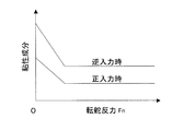
- the friction component to be added in the separate item adding unit 25 that is, the value “a” of the friction term is decreased as the estimated turning reaction force F h is increased, and is set to 0 above a certain threshold.
- the turning reaction force F h is small only if it is possible to impart friction components.
- the value of the friction term may be constant without changing as shown in FIG.
- the forward / reverse correspondence processing unit 22 sets the coefficient b of the viscosity term larger in the case of reverse input than in the case of positive input in the addition process of the separate item addition unit 25.
- the viscous component can suppress vibration around the neutral position when letting go, and can prevent a sense of incongruity that the steering reaction force at the time of positive input becomes too large.
- Coefficient of viscosity term b may be smaller the larger the load, i.e. the turning reaction force F h. With this setting, the turning reaction force F h it is possible to impart greater viscosity component is smaller.
- the viscosity component (viscosity coefficient b) decreases as the turning reaction force F h increases, and the above-described constant value is obtained. The above is determined to be constant.
- the turning reaction force F h is detected by the turning reaction force detection means 18 calculated from the turning motor torque or the like.
- the turning reaction force detection means 18 instead of providing the turning reaction force detection means 18, however. by turning reaction force detecting means 18A composed of a turning reaction force sensor load cell or the like load sensor provided in the steering mechanism 6, it may be detected the turning reaction force F h.
- the detected turning reaction force F h of the turning reaction force sensor such as the load cell and the load sensor, the input determination and by forward and reverse determination unit 21, provisional steering target value calculation of the steering reaction force target value computing section 17 This is used to calculate the provisional steering reaction force target value Paa and the steering reaction force target value Pa by the unit 24.
Abstract
La présente invention porte sur une direction à commande électrique. Elle assure une bonne réponse lorsque l'on a commencé à tourner un volant de direction à partir d'une position neutre, et elle rend possible la position de retour au moment où les mains sont retirés du volant de direction à la position neutre dans la mesure tout en évitant une vibration autour de la position neutre. Un capteur d'angle de direction (5) et un moteur de force de réaction de braquage (4) sont utilisés pour un volant de direction (3) qui n'est pas couplé mécaniquement à un arbre inter-biellettes de direction (2). Un moyen de commande de la direction (12) commande un moteur de braquage (7) d'un mécanisme de braquage (6) pour entraîner l'arbre inter-biellettes de direction (2) sur la base de l'angle de braquage. Le moyen de commande de braquage (12) est équipé d'une unité de commande de la force de réaction de braquage (14) qui détermine une entrée vers l'avant lorsque le sens de braquage et le sens de la force de réaction de braquage sont différents, détermine une entrée vers l'arrière lorsque les deux sens sont les mêmes et commande la force de réaction de braquage du moteur de force de réaction de braquage en fonction de l'entrée vers l'avant ou vers l'arrière.
Applications Claiming Priority (2)
| Application Number | Priority Date | Filing Date | Title |
|---|---|---|---|
| JP2010282595A JP5697966B2 (ja) | 2010-12-20 | 2010-12-20 | ステアバイワイヤの操舵反力制御装置 |
| JP2010-282595 | 2010-12-20 |
Publications (1)
| Publication Number | Publication Date |
|---|---|
| WO2012086502A1 true WO2012086502A1 (fr) | 2012-06-28 |
Family
ID=46313778
Family Applications (1)
| Application Number | Title | Priority Date | Filing Date |
|---|---|---|---|
| PCT/JP2011/078993 WO2012086502A1 (fr) | 2010-12-20 | 2011-12-15 | Dispositif de commande de la force de réaction de braquage pour une direction à commande électrique |
Country Status (2)
| Country | Link |
|---|---|
| JP (1) | JP5697966B2 (fr) |
| WO (1) | WO2012086502A1 (fr) |
Cited By (4)
| Publication number | Priority date | Publication date | Assignee | Title |
|---|---|---|---|---|
| EP2610131A1 (fr) * | 2011-12-26 | 2013-07-03 | Jtekt Corporation | Système de direction |
| CN109552401A (zh) * | 2017-09-27 | 2019-04-02 | 株式会社捷太格特 | 车辆用控制装置 |
| US10336344B2 (en) | 2016-02-16 | 2019-07-02 | Toyota Jidosha Kabushiki Kaisha | Vehicle control apparatus |
| CN112566835A (zh) * | 2018-08-08 | 2021-03-26 | 日产自动车株式会社 | 转向控制方法和转向控制装置 |
Families Citing this family (2)
| Publication number | Priority date | Publication date | Assignee | Title |
|---|---|---|---|---|
| KR102004348B1 (ko) * | 2017-09-29 | 2019-07-29 | 주식회사 만도 | Sbw 시스템에서 조향 반력 생성 장치 및 방법 |
| US11046359B2 (en) | 2017-09-25 | 2021-06-29 | Mando Corporation | Steer-by-wire system and control method thereof |
Citations (7)
| Publication number | Priority date | Publication date | Assignee | Title |
|---|---|---|---|---|
| JP2002029441A (ja) * | 2000-07-19 | 2002-01-29 | Mitsubishi Electric Corp | 電動式ステアリング装置の制御装置 |
| JP2005335613A (ja) * | 2004-05-28 | 2005-12-08 | Mitsubishi Electric Corp | 車両用操舵装置 |
| JP2006069351A (ja) * | 2004-09-01 | 2006-03-16 | Toyota Motor Corp | 車両の操舵装置 |
| JP2007090924A (ja) * | 2005-09-27 | 2007-04-12 | Toyota Motor Corp | 車両の操舵装置 |
| JP2007137287A (ja) * | 2005-11-18 | 2007-06-07 | Toyota Motor Corp | 車両の操舵装置 |
| JP2008024092A (ja) * | 2006-07-19 | 2008-02-07 | Toyota Motor Corp | 車両の操舵装置 |
| JP2010168008A (ja) * | 2009-01-26 | 2010-08-05 | Nissan Motor Co Ltd | ステアリング装置、ステアリング制御方法 |
-
2010
- 2010-12-20 JP JP2010282595A patent/JP5697966B2/ja not_active Expired - Fee Related
-
2011
- 2011-12-15 WO PCT/JP2011/078993 patent/WO2012086502A1/fr active Application Filing
Patent Citations (7)
| Publication number | Priority date | Publication date | Assignee | Title |
|---|---|---|---|---|
| JP2002029441A (ja) * | 2000-07-19 | 2002-01-29 | Mitsubishi Electric Corp | 電動式ステアリング装置の制御装置 |
| JP2005335613A (ja) * | 2004-05-28 | 2005-12-08 | Mitsubishi Electric Corp | 車両用操舵装置 |
| JP2006069351A (ja) * | 2004-09-01 | 2006-03-16 | Toyota Motor Corp | 車両の操舵装置 |
| JP2007090924A (ja) * | 2005-09-27 | 2007-04-12 | Toyota Motor Corp | 車両の操舵装置 |
| JP2007137287A (ja) * | 2005-11-18 | 2007-06-07 | Toyota Motor Corp | 車両の操舵装置 |
| JP2008024092A (ja) * | 2006-07-19 | 2008-02-07 | Toyota Motor Corp | 車両の操舵装置 |
| JP2010168008A (ja) * | 2009-01-26 | 2010-08-05 | Nissan Motor Co Ltd | ステアリング装置、ステアリング制御方法 |
Cited By (7)
| Publication number | Priority date | Publication date | Assignee | Title |
|---|---|---|---|---|
| EP2610131A1 (fr) * | 2011-12-26 | 2013-07-03 | Jtekt Corporation | Système de direction |
| US8662240B2 (en) | 2011-12-26 | 2014-03-04 | Jtekt Corporation | Steering system |
| US10336344B2 (en) | 2016-02-16 | 2019-07-02 | Toyota Jidosha Kabushiki Kaisha | Vehicle control apparatus |
| CN109552401A (zh) * | 2017-09-27 | 2019-04-02 | 株式会社捷太格特 | 车辆用控制装置 |
| CN112566835A (zh) * | 2018-08-08 | 2021-03-26 | 日产自动车株式会社 | 转向控制方法和转向控制装置 |
| CN112566835B (zh) * | 2018-08-08 | 2023-01-10 | 日产自动车株式会社 | 转向控制方法和转向控制装置 |
| US11603128B2 (en) | 2018-08-08 | 2023-03-14 | Nissan Motor Co., Ltd. | Steering control method and steering control device |
Also Published As
| Publication number | Publication date |
|---|---|
| JP5697966B2 (ja) | 2015-04-08 |
| JP2012131246A (ja) | 2012-07-12 |
Similar Documents
| Publication | Publication Date | Title |
|---|---|---|
| JP4984110B2 (ja) | 電動パワーステアリング装置 | |
| EP1837266B1 (fr) | Controleur de dispositif de direction a assistance electrique | |
| JP5109342B2 (ja) | 電動パワーステアリング装置 | |
| JP4561806B2 (ja) | 電動パワーステアリング装置 | |
| WO2012086502A1 (fr) | Dispositif de commande de la force de réaction de braquage pour une direction à commande électrique | |
| JP5313729B2 (ja) | 電動パワーステアリング装置 | |
| JP4380697B2 (ja) | 車両用操舵制御装置 | |
| WO2012014399A1 (fr) | Dispositif de direction assistée électrique | |
| JP2007125973A (ja) | 車両用操舵装置 | |
| JP2006199219A (ja) | 電動パワーステアリング装置の制御装置 | |
| JP4581694B2 (ja) | 電動パワーステアリング装置の制御装置 | |
| JP2008018825A (ja) | 電動パワーステアリング装置の制御装置 | |
| JP4530880B2 (ja) | 車両の運動状態制御装置 | |
| JP2009023608A (ja) | 車両用操舵装置 | |
| JP5140158B2 (ja) | 電動式パワーステアリング制御装置 | |
| JP2006137215A (ja) | ステアバイワイヤ式ステアリング装置の操舵反力制御装置 | |
| JP4404693B2 (ja) | 車両用操舵装置 | |
| JP4906333B2 (ja) | 車両の操舵装置 | |
| JP4815958B2 (ja) | 電動パワーステアリング装置 | |
| JP2008062837A (ja) | 車両用操舵制御装置 | |
| JP4011424B2 (ja) | ステアリング制御装置 | |
| JP5844861B2 (ja) | ステアバイワイヤの操舵反力制御装置 | |
| JP5772344B2 (ja) | 車両用操舵装置 | |
| KR100795102B1 (ko) | 전자제어 파워 스티어링 시스템의 복원제어장치 | |
| JP2006175981A (ja) | 操舵制御装置 |
Legal Events
| Date | Code | Title | Description |
|---|---|---|---|
| 121 | Ep: the epo has been informed by wipo that ep was designated in this application |
Ref document number: 11851165 Country of ref document: EP Kind code of ref document: A1 |
|
| NENP | Non-entry into the national phase |
Ref country code: DE |
|
| 122 | Ep: pct application non-entry in european phase |
Ref document number: 11851165 Country of ref document: EP Kind code of ref document: A1 |