WO2012086502A1 - Steering reaction force control device for steer-by-wire - Google Patents
Steering reaction force control device for steer-by-wire Download PDFInfo
- Publication number
- WO2012086502A1 WO2012086502A1 PCT/JP2011/078993 JP2011078993W WO2012086502A1 WO 2012086502 A1 WO2012086502 A1 WO 2012086502A1 JP 2011078993 W JP2011078993 W JP 2011078993W WO 2012086502 A1 WO2012086502 A1 WO 2012086502A1
- Authority
- WO
- WIPO (PCT)
- Prior art keywords
- steering
- reaction force
- steering reaction
- input
- reverse
- Prior art date
Links
Images


Classifications
-
- B—PERFORMING OPERATIONS; TRANSPORTING
- B62—LAND VEHICLES FOR TRAVELLING OTHERWISE THAN ON RAILS
- B62D—MOTOR VEHICLES; TRAILERS
- B62D6/00—Arrangements for automatically controlling steering depending on driving conditions sensed and responded to, e.g. control circuits
- B62D6/008—Control of feed-back to the steering input member, e.g. simulating road feel in steer-by-wire applications
Definitions
- the present invention relates to a steer-by-wire type steering apparatus that is steered by a steering wheel that is not mechanically connected to a shaft between tie rods for steering, and more particularly, a steering reaction force that controls a steering reaction force applied to the steering wheel.
- the present invention relates to a force control device.
- the steering reaction force acting on the steering mechanism is detected by the steering reaction force sensor, or the steering reaction force is controlled using the control amount of the steering motor and the steering displacement amount.
- a method for estimating a force and generating a steering reaction force according to a steering reaction force is known (for example, Patent Document 1). Further, in order to improve the steering feeling, friction and viscosity components are added to the steering reaction force (Patent Documents 2 to 4).
- the frictional force in the mechanism is directly felt as a steering reaction force.
- the steer-by-wire has a problem that the friction in the mechanism portion is small and the initial steering reaction force is less responsive when the handle starts to be turned from the neutral position.
- the steer-by-wire when trying to generate a frictional force by control, since it is a non-linear element whose sign is inverted depending on the steering direction, it is difficult to reproduce a steering reaction force that is always stable and has no sense of incongruity.
- Patent Document 2 mechanical friction is applied to the steering wheel.
- an offset occurs in the return position when the hand is released, and the vehicle may flow in a single direction.
- Patent Document 3 the gain of the steering reaction force is increased in a region where the steering angle is small.
- this method tends to generate vibrations around the neutral position.
- Patent Document 4 in order to prevent an offset of the return position at the time of releasing, by multiplying the provisional target friction reaction force by the larger one of the first coefficient based on the steering angle and the second coefficient based on the steering angular velocity, The target friction reaction force is set to zero when the hand is released in the neutral position. However, the steering reaction force at the start of cutting from the neutral position is less responsive.
- the present invention has been made to solve the above-described problems, and ensures a good response when the steering wheel starts to be turned from the neutral position, prevents vibration around the neutral position, and returns to the return position when released.
- the goal is to make the position as neutral as possible.
- the steer-by-wire steering reaction force control device includes a steering angle sensor 5 that detects a steering angle with respect to a steering wheel 3 that is not mechanically connected to the steering tie rod shaft 2, and a steering reaction force.
- a steering reaction force motor 4 is provided, and based on the steering angle detected by the steering angle sensor 5, a command signal for the turning angle is combined with a driving state detection signal from another sensor 15 mounted on the vehicle.
- a steer-by-wire steering device having a steering control means 12 for controlling the steering motor 7 of the steering mechanism 6 that generates and drives the shaft 2 between the tie rods when the steering direction and the direction of the steering reaction force are different.
- the steering reaction force control unit 14 determines whether the input to the steering mechanism 6 is normal or reverse based on the steering direction and the direction of the steering reaction force.
- the steering reaction force of the steering reaction force motor 74 is controlled in accordance with the normal / reverse direction. For example, when the transmission efficiency between the forward input and the reverse input of the steering mechanism 6 is different, the steering reaction force is accurately estimated by changing the coefficient used for the steering reaction force estimation between the normal input and the reverse input. be able to.
- steering reaction force detection means 18, 18A for detecting a steering reaction force acting on the steering mechanism 6, and a steering direction detection means 19 for detecting a steering direction, and the steering reaction force control section.
- 14 is detected by a steering reaction force target value calculation unit 17 that calculates a target value of the steering reaction force of the steering reaction force motor 4 according to a predetermined rule, and the steering direction detection means 18 and 18A.
- An input forward / reverse determining unit 21 that determines that the steering direction differs from the direction of the steering reaction force detected by the steering reaction force detection means 18 and 18A, and that the input is a reverse input when the direction is the same.
- a normal / reverse correspondence processing unit 22 that changes the calculation content of the steering target value calculation unit 17 according to the normal / reverse that is the determination result of the input normal / reverse determination unit 21 can be provided.
- the steering direction detection means 19 may be the steering angle sensor 5. That is, the steering direction used for the determination by the input forward / reverse determination unit 21 may be obtained from the steering angle sensor 5.
- the turning reaction force detecting means 18 may estimate the turning reaction force from the torque of the turning motor 7 and the turning displacement amount according to a predetermined estimation formula.
- the forward / reverse correspondence processing unit 22 has a function of changing a coefficient for estimating the turning reaction force in the estimation formula based on the forward input or the reverse input determined by the input forward / reverse determination unit 21. It is also good.
- the steering reaction force can be accurately estimated by changing the coefficient used for the steering reaction force estimation between the normal input and the reverse input. it can.
- a low-pass filter 26 that can change the cutoff frequency is provided as a filter that passes the detection signal of the steering reaction force detected by the steering reaction force detection means 18, and is obtained through the low-pass filter 26.
- the steering reaction force target value calculation unit 17 may use the steered reaction force as the basic value of the target steering reaction force, that is, the provisional steering reaction force target value.
- the cut-off frequency of the low-pass filter 26 is preferably set high when the steering reaction force is large and low when the steering reaction force is small.
- the estimated turning reaction force is passed through a low-pass filter 26 that can change the cutoff frequency, and a provisional steering reaction force target value is generated.
- the cut-off frequency is lowered, and when the estimated turning reaction force is large, the cut-off frequency is raised. As a result, it is possible to suppress vibration during hand release and to obtain a quick steering reaction force.
- a cutoff frequency changing means 27 for changing the cutoff frequency of the low-pass filter 26 by an input from the switching operation means 28 may be provided.
- the steering reaction force control unit 14 applies a friction component to the steering reaction force target value when the determination result of the input normal / reverse determination unit 21 is a positive input, and does not apply it when the input is a reverse input. It is good as a thing.
- the steering reaction force control unit 14 adds a friction term, a viscosity term, and an inertia term to the provisional steering reaction force target value to generate a steering reaction force target value.
- the friction component is applied only when the input is positive. Thereby, when the steering wheel is started to be turned from the neutral position, the friction component is quickly given, and it is possible to realize the responsiveness of the steering reaction force at the initial stage of steering. In the case of reverse input, no friction component is applied, so that there is no offset of the return position when releasing the hand.
- the steering reaction force control unit 14 sets the friction component to be smaller as the turning reaction force is larger. Further, the steering reaction force control unit 14 sets the coefficient of the viscosity term to be added to the steering reaction force target value to a value larger than that in the case of positive input when the determination result of the input normal / reverse determination unit is reverse input. It is good. Furthermore, it is preferable that the steering reaction force control unit 14 sets the coefficient of the viscosity term to be smaller as the turning reaction force is larger. In the case of reverse input, by setting the coefficient of the viscosity term to be larger than that in the case of positive input, vibration around the neutral position can be suppressed, and the steering reaction force at the time of positive input can be prevented from becoming too strange. Can do.
- FIG. 1 is a system configuration diagram of a steer-by-wire type steering apparatus provided with a steering reaction force control apparatus according to this embodiment.
- the steering mechanism 1 includes a steering reaction force motor 4 that generates a steering reaction force against a steering wheel 3 that is not mechanically connected to the shaft 2 between tie rods for steering, and a steering angle sensor 5 that detects a steering angle.
- the steering mechanism 6 includes a steering motor 7 that drives the shaft 2 between tie rods to advance and retreat in the vehicle width direction, and a position sensor 8 that detects an advancing / retreating position as a steering displacement amount of the shaft position 2 between the tie rods.
- torque detecting means 9 such as an ammeter for detecting the torque of the turning motor 7 and a rotation angle detecting means 10 for detecting the rotation angle of the turning motor 7 are provided.
- the steering control means 12 is provided in an ECU (electric control unit) 11 that controls the entire vehicle, and includes a steering control unit 13 and a steering reaction force control unit 14.
- the ECU 11 includes a computer, a program executed on the computer, and an electronic circuit. Based on the steering angle detected by the steering angle sensor 5, the steering control unit 13 generates a steering angle command signal together with driving state detection signals from other sensors 15 mounted on the vehicle. It is means for controlling the steering motor 7 of the rudder mechanism 6.
- the other sensors 15 are, for example, a vehicle speed sensor or a sensor that detects a load acting on each wheel 16. The other sensors 15 may be one or plural, but here, one sensor 15 is shown as a representative.
- the steering reaction force control unit 14 basically calculates a steering reaction force target value Pa by a steering reaction force target value calculation unit 17 according to a predetermined rule, and a motor control circuit (not shown) of the steering reaction force motor 4. 2).
- a steering reaction force target value calculation unit 17 when the calculation by the steering target value calculation unit 17 is performed, when the steering direction and the direction of the steering reaction force are different, it is determined that the input is normal, and when the direction is the same, the reverse input is determined. Accordingly, the steering reaction force of the steering reaction force motor 4 is controlled.
- a turning reaction force detecting means 18 for detecting a turning reaction force acting on the turning mechanism 6 (FIG. 1) and a steering direction detecting means 19 for detecting a steering direction are provided.
- the steering direction detection means 19 is the steering angle sensor 5 or the position sensor 8 of the steering mechanism 6.
- the steering reaction force control unit 14 includes a steering reaction force target value calculation unit 17, an input normal / reverse determination unit 21, and a normal / reverse correspondence processing unit 22.
- the steering reaction force target value calculation unit 17 is a means for calculating the target value Pa of the steering reaction force of the steering motor 4 according to a predetermined rule.
- the input normal / reverse determination unit 21 is a normal input and the same direction. Is a means for determining reverse input.
- the forward / reverse response processing unit 22 is means for changing the calculation content by the steering reaction force target value calculation unit 17 in accordance with the normal / reverse which is the determination result of the input normal / reverse determination unit 21.
- the turning reaction force detection means 18 estimates the turning reaction force F h from the torque of the turning motor and the amount of turning displacement according to a predetermined estimation equation, for example, the following equation (1).
- the equation (1) is a turning reaction force F h, the generated torque T m of a turning motor 7, the steering speed (differential value of the steering motor rotation angle theta), and the steering acceleration (steering motor rotation angle This is a formula calculated from the twice differential value of ⁇ .
- the generated torque T m of the steered motor 7 is obtained from the torque detecting means 9 of the steered motor 7, and the rotation angle ⁇ of the steered motor 7 is obtained from the rotational angle detecting means 10.
- the torque T m detected by the torque detection means 9 is inputted to the turning reaction force detection means 18 through the low-pass filter 23 to remove high frequency components. If there are no high-frequency components in the steering motor torque T m, the low-pass filter 23 is not required.
- the positive inverse correspondence processing unit 22 the positive input or reverse input, which is determined by the input normal and reverse determination unit 21, the coefficient estimates the turning reaction force F h on the estimate equation (1) A, I, c , F It has a function of changing f according to a predetermined rule (not shown).
- the change of the coefficient may be to change any one of the coefficients A, I, c, and F f , or to change any two or all of them.
- the steering reaction force target value calculation unit 17 includes a provisional steering reaction force target value calculation unit 24 and a separate addition unit 25, and the provisional steering reaction force target value Paa calculated by the provisional steering reaction force target value calculation unit 24.
- a separate item which will be described later, is added by a separate item adding unit 25 to obtain a steering reaction force target value Pa.
- the provisional steering reaction force target value calculation unit 24 has a low-pass filter 26 whose cutoff frequency can be changed, and the turning reaction force detected by the turning reaction force detection means 18 (the turning reaction force estimated value). the turning reaction force obtained through F h to the low pass filter 26, the basic value of the target steering reaction force Pa, i.e. a provisional steering reaction force target value Paa.
- the calculation of the formula (1) by the turning reaction force detection means 18 is performed at 1 kHz (1 msec cycle), and the result (digital signal waveform) is a low-pass filter 26 with a variable cut-off frequency (the cut-off frequency is (30Hz to about 0.5Hz).
- the low-pass filter 23 is also a software digital filter. For these calculations, for example, an SH microcomputer is used.
- Cut-off frequency of said variable cutoff frequency of the low pass filter 26 may be a constant, but higher when turning reaction force F h is large, it is preferable is set low when small.
- the low-pass filter 26 is provided with a cut-off frequency changing means 27 that monitors the input turning reaction force F h and changes the cut-off frequency when the turning reaction force F h is high and low when the turning reaction force F h is small. ing. This change may be continuous or gradual.
- the cutoff frequency changing unit 27 may change the cutoff frequency of the low-pass filter 26 by an input from the switching operation unit 28.
- the switching operation means 28 is provided on, for example, a vehicle console or an exterior surface of an ECU. Cut-off frequency changing unit 27, a cut-off frequency, the switching can be changed by an input from the operation unit 28, and a cut-off frequency changing its further as described above by turning reaction force F h input It may be changed.
- the separate item adding unit 25 adds the friction term, the viscosity term, and the inertia term to the provisional steering reaction force target value Paa calculated by the provisional steering reaction force target value calculation unit 24 to generate a steering reaction force target value Pa.
- the addition of the friction term, the viscosity term, and the inertia term by the separate term adding unit 25 is changed to the normal / reverse correspondence processing unit 22 according to the normal / reverse determination result of the input normal / reverse determination unit 21. The details of the change will be described later together with an explanation of the overall operation.
- FIG. 3 is a flowchart for calculating the steering reaction force target value Pa.
- the steering direction is detected by the steering direction detecting means 19 shown in FIG.
- the steering direction detection means 19 is the steering angle sensor 5 of the steering mechanism 1 or the position sensor 8 of the steering mechanism 6, and any of the steering direction detection means 19 may detect the steering direction.
- the steering torque generated T m of a motor 7 is detected by the torque detection unit 9, and detects the steering speed and steering acceleration in the rotation detecting means 10 reads the turning reaction force detecting means 18. If it contains high frequency components in the steering motor torque T m, is passed through a low-pass filter 23, high frequency components are removed (step S2).
- the turning speed is a differential value of the turning motor rotation angle ⁇
- the turning acceleration is a twice differential value of the turning motor rotation angle ⁇
- the turning detection unit 10 reads the turning motor rotation angle ⁇ .
- the turning reaction force detecting means 18 calculates the turning speed and turning acceleration from the turning motor rotation angle ⁇ .
- the turning reaction force detection means 18 generates the generated torque T m , the turning speed (the differential value of the turning motor rotation angle ⁇ ), and the turning acceleration (the second derivative of the turning motor rotation angle ⁇ ). from the value), according to the following equation (1) described above, calculates the turning reaction force F h (step S3). This calculated value is an estimated value of the steering reaction force.
- the input normal / reverse determination unit 21 determines whether the input is normal or reverse based on the steering direction detected by the steering direction detection means 19 and the turning reaction force detected by the turning reaction force detection means 18 (step S4).
- the input forward / reverse determination unit 21 determines that the input to the steering mechanism 6 is a positive input when the steering direction and the direction of the estimated steering reaction force are different, and a reverse input when the direction is the same. When the steering angular velocity is 0, the input is reversed.
- the provisional steering reaction force target value calculation unit 24 of the steering reaction force target value calculation unit 17 is a low-pass capable of changing the cut-off frequency of the turning reaction force F h estimated by the turning reaction force detection means 18 as described above.
- the provisional steering reaction force target value Paa is generated through the filter 26 (step S5).
- the cut-off frequency changing unit 27 to lower the cutoff frequency when the estimated turning reaction force F h inputted is small, when the estimated turning reaction force is large to increase the cut-off frequency. Thereby, vibration at the time of releasing the steering wheel 3 can be suppressed, and a quick steering reaction force can be obtained.
- Estimated turning reaction force F h is greater than or less of criteria, and is either in which value the cut-off frequency, optionally may be determined by the design by simulation or the like.
- the cut-off frequency changing means 27 can change the cut-off frequency by the operation of the change-over operation means 28, and by this change, the steering feeling can be changed according to the preference of the driver.
- the separate item adding unit 25 adds the friction term, the viscosity term, and the inertia term to the provisional steering reaction force target value Paa calculated as described above, and generates the steering reaction force target value Pa (step S6).
- ⁇ SW Steering angle (steering wheel angle)
- a Friction term
- b Coefficient of viscosity term
- d Coefficient of inertia term
- the friction term, the viscosity term, and the inertia terms a, b, and d are appropriately set and determined.
- the forward / reverse correspondence processing unit 22 gives a friction term (that is, a friction component) only in the case of a positive input in the addition process of the separate item addition unit 25.
- a friction term that is, a friction component
- the steering wheel 3 starts to be turned from the neutral position, a friction component is quickly given, and a responsive feeling of the steering reaction force at the initial stage of steering can be realized.
- no friction component is applied, so that there is no offset of the return position when releasing the hand.
- the friction component to be added in the separate item adding unit 25 that is, the value “a” of the friction term is decreased as the estimated turning reaction force F h is increased, and is set to 0 above a certain threshold.
- the turning reaction force F h is small only if it is possible to impart friction components.
- the value of the friction term may be constant without changing as shown in FIG.
- the forward / reverse correspondence processing unit 22 sets the coefficient b of the viscosity term larger in the case of reverse input than in the case of positive input in the addition process of the separate item addition unit 25.
- the viscous component can suppress vibration around the neutral position when letting go, and can prevent a sense of incongruity that the steering reaction force at the time of positive input becomes too large.
- Coefficient of viscosity term b may be smaller the larger the load, i.e. the turning reaction force F h. With this setting, the turning reaction force F h it is possible to impart greater viscosity component is smaller.
- the viscosity component (viscosity coefficient b) decreases as the turning reaction force F h increases, and the above-described constant value is obtained. The above is determined to be constant.
- the turning reaction force F h is detected by the turning reaction force detection means 18 calculated from the turning motor torque or the like.
- the turning reaction force detection means 18 instead of providing the turning reaction force detection means 18, however. by turning reaction force detecting means 18A composed of a turning reaction force sensor load cell or the like load sensor provided in the steering mechanism 6, it may be detected the turning reaction force F h.
- the detected turning reaction force F h of the turning reaction force sensor such as the load cell and the load sensor, the input determination and by forward and reverse determination unit 21, provisional steering target value calculation of the steering reaction force target value computing section 17 This is used to calculate the provisional steering reaction force target value Paa and the steering reaction force target value Pa by the unit 24.
Abstract
The present invention ensures good response when a steering wheel is started to turn from a neutral position, and makes the return position when hands are taken off the steering wheel the neutral position to the extent possible while preventing vibration around the neutral position. A steering angle sensor (5) and a steering reaction force motor (4) are provided for a steering wheel (3) which is not mechanically coupled to an inter-tie-rod shaft (2). A steering control means (12) controls a turning motor (7) of a turning mechanism (6) for driving the inter-tie-rod shaft (2) on the basis of the steering angle. The steering control means (12) is provided with a steering reaction force control unit (14) which determines forward input when the steering direction and the direction of turning reaction force are different, determines reverse input when both the directions are the same direction, and controls the steering reaction force of the steering reaction force motor according to the forward or reverse input.
Description
本出願は、2010年12月20日出願の特願2010-282595の優先権を主張するものであり、その全体を参照により本願の一部をなすものとして引用する。
This application claims the priority of Japanese Patent Application No. 2010-282595 filed on Dec. 20, 2010, which is incorporated herein by reference in its entirety.
この発明は、転舵用のタイロッド間シャフトと機械的に連結されていないステアリングホイールで操舵を行うようにしたステアバイワイヤ式操舵装置に関し、特にそのステアリングホイールに付与する操舵反力を制御する操舵反力制御装置に関する。
The present invention relates to a steer-by-wire type steering apparatus that is steered by a steering wheel that is not mechanically connected to a shaft between tie rods for steering, and more particularly, a steering reaction force that controls a steering reaction force applied to the steering wheel. The present invention relates to a force control device.
ステアリングホイールに付与する操舵反力の生成法に関して、転舵機構に働く転舵反力を転舵反力センサにより検出し、あるいは転舵モータの制御量及び転舵変位量を用いて転舵反力を推定し、転舵反力に応じて操舵反力を生成する方法が知られている(例えば、特許文献1)。また、操舵フィーリングを向上するために、操舵反力に摩擦や粘性成分を付与している(特許文献2~4)。
Regarding the method of generating the steering reaction force applied to the steering wheel, the steering reaction force acting on the steering mechanism is detected by the steering reaction force sensor, or the steering reaction force is controlled using the control amount of the steering motor and the steering displacement amount. A method for estimating a force and generating a steering reaction force according to a steering reaction force is known (for example, Patent Document 1). Further, in order to improve the steering feeling, friction and viscosity components are added to the steering reaction force (Patent Documents 2 to 4).
従来のタイロッド間シャフトとステアリングホイールが機械的に連結されているEPS等の操舵装置では、機構部における摩擦力が直接操舵反力として感じられる。一方、ステアバイワイヤにおいては、機構部における摩擦が小さく、ハンドルを中立位置から切り始めた際には、初期の操舵反力は手応え感が小さいという問題点がある。ステアバイワイヤにおいて、摩擦力を制御により生成しようとする場合、操舵方向によって符号が反転する非線形要素であるため、常時安定かつ違和感のない操舵反力を再現することは難しい。
In a conventional steering device such as EPS in which the shaft between the tie rods and the steering wheel are mechanically coupled, the frictional force in the mechanism is directly felt as a steering reaction force. On the other hand, the steer-by-wire has a problem that the friction in the mechanism portion is small and the initial steering reaction force is less responsive when the handle starts to be turned from the neutral position. In the steer-by-wire, when trying to generate a frictional force by control, since it is a non-linear element whose sign is inverted depending on the steering direction, it is difficult to reproduce a steering reaction force that is always stable and has no sense of incongruity.
特許文献2ではステアリングホイールに機械的に摩擦を付与している。しかし、この方法では、手放し時に於ける戻り位置にオフセットが生じ、車両が片流れする場合がある。特許文献3では操舵角の小さい領域で操舵反力のゲインを大きくしている。しかし、この方法では中立回りで振動が発生しやすくなる。特許文献4では、手放し時に於ける戻り位置のオフセットを防ぐため、操舵角に基づく第1の係数と操舵角速度に基づく第2の係数のどちらか大きい方を暫定目標摩擦反力に乗ずることで、中立位置での手放し時には目標摩擦反力を0としている。しかし、中立位置から切り始め時の操舵反力は手応え感が小さくなる。
In Patent Document 2, mechanical friction is applied to the steering wheel. However, in this method, an offset occurs in the return position when the hand is released, and the vehicle may flow in a single direction. In Patent Document 3, the gain of the steering reaction force is increased in a region where the steering angle is small. However, this method tends to generate vibrations around the neutral position. In Patent Document 4, in order to prevent an offset of the return position at the time of releasing, by multiplying the provisional target friction reaction force by the larger one of the first coefficient based on the steering angle and the second coefficient based on the steering angular velocity, The target friction reaction force is set to zero when the hand is released in the neutral position. However, the steering reaction force at the start of cutting from the neutral position is less responsive.
この発明は、上記課題を解決するためになされたものであり、ステアリングホイールを中立位置から切り始めた際の良好な手応えを確保し、中立位置周りでの振動を防ぎつつ、手放し時における戻り位置を出来るだけ中立位置にすることを目的とする。以下、この発明の概要について、実施形態を示す図面中の符号を用いて説明する。
The present invention has been made to solve the above-described problems, and ensures a good response when the steering wheel starts to be turned from the neutral position, prevents vibration around the neutral position, and returns to the return position when released. The goal is to make the position as neutral as possible. Hereinafter, the outline of the present invention will be described using reference numerals in the drawings showing embodiments.
この発明のステアバイワイヤの操舵反力制御装置は、転舵用のタイロッド間シャフト2と機械的に連結されていないステアリングホイール3に対し、操舵角を検出する操舵角センサ5と、操舵反力を与える操舵反力モータ4とが設けられ、操舵角センサ5の検出した操舵角を基に、車両に装備された他のセンサ類15からの運転状態検出信号と合わせて転舵角の指令信号を生成し、タイロッド間シャフト2を駆動する転舵機構6の転舵モータ7を制御するステアリング制御手段12を有するステアバイワイヤ式操舵装置であって、操舵方向と転舵反力の方向とが異なる場合には正入力、同方向の場合には逆入力と判定し、この正逆に応じて前記操舵反力モータの操舵反力を制御する操舵反力制御部14を設けたものである。
The steer-by-wire steering reaction force control device according to the present invention includes a steering angle sensor 5 that detects a steering angle with respect to a steering wheel 3 that is not mechanically connected to the steering tie rod shaft 2, and a steering reaction force. A steering reaction force motor 4 is provided, and based on the steering angle detected by the steering angle sensor 5, a command signal for the turning angle is combined with a driving state detection signal from another sensor 15 mounted on the vehicle. A steer-by-wire steering device having a steering control means 12 for controlling the steering motor 7 of the steering mechanism 6 that generates and drives the shaft 2 between the tie rods when the steering direction and the direction of the steering reaction force are different. Is provided with a steering reaction force control unit 14 that determines a positive input and a reverse input in the same direction and controls the steering reaction force of the steering reaction force motor according to the normal and reverse directions.
この構成によると、操舵反力制御部14は、操舵方向と転舵反力の方向から転舵機構6にかかる入力の正逆を判定する。操舵方向と転舵反力の方向が異なる場合には正入力、同方向の場合には逆入力と判定する。この正逆に応じて前記操舵反力モータ74の操舵反力を制御する。例えば、転舵機構6の正入力と逆入力における伝達効率が異なる場合、転舵反力推定に用いる係数を正入力時と逆入力時で変更することにより,転舵反力を精度良く推定することができる。これにより、ステアリングホイール3を中立位置から切り始めた際の良好な手応えを確保し、中立位置周りでの振動を防ぎつつ、手放し時における戻り位置を出来るだけ中立位置にすることができる。
According to this configuration, the steering reaction force control unit 14 determines whether the input to the steering mechanism 6 is normal or reverse based on the steering direction and the direction of the steering reaction force. When the steering direction and the direction of the steering reaction force are different, it is determined that the input is positive, and when the direction is the same, it is determined that the input is reverse. The steering reaction force of the steering reaction force motor 74 is controlled in accordance with the normal / reverse direction. For example, when the transmission efficiency between the forward input and the reverse input of the steering mechanism 6 is different, the steering reaction force is accurately estimated by changing the coefficient used for the steering reaction force estimation between the normal input and the reverse input. be able to. As a result, it is possible to secure a good response when the steering wheel 3 starts to be turned from the neutral position, and to prevent the vibration around the neutral position, and to set the return position when released to the neutral position as much as possible.
この発明において、前記転舵機構6に作用する転舵反力を検出する転舵反力検出手段18,18Aと、操舵方向を検出する操舵方向検出手段19とを設け、前記操舵反力制御部14は、具体的には、定められた規則に従って前記操舵反力モータ4の操舵反力の目標値を演算する操舵反力目標値演算部17と、前記操舵方向検出手段18,18Aで検出される操舵方向が前記転舵反力検出手段18,18Aで検出される転舵反力の方向と異なる場合には正入力、同方向の場合には逆入力と判定する入力正逆判定部21と、前記入力正逆判定部21の判定結果となる正逆に応じて前記操舵目標値演算部17による演算内容を変更する正逆対応処理部22とを有するものとできる。
In the present invention, there are provided steering reaction force detection means 18, 18A for detecting a steering reaction force acting on the steering mechanism 6, and a steering direction detection means 19 for detecting a steering direction, and the steering reaction force control section. Specifically, 14 is detected by a steering reaction force target value calculation unit 17 that calculates a target value of the steering reaction force of the steering reaction force motor 4 according to a predetermined rule, and the steering direction detection means 18 and 18A. An input forward / reverse determining unit 21 that determines that the steering direction differs from the direction of the steering reaction force detected by the steering reaction force detection means 18 and 18A, and that the input is a reverse input when the direction is the same. A normal / reverse correspondence processing unit 22 that changes the calculation content of the steering target value calculation unit 17 according to the normal / reverse that is the determination result of the input normal / reverse determination unit 21 can be provided.
前記操舵方向検出手段19は、前記操舵角センサ5であっても良い。すなわち、前記入力正逆判定部21で判断に用いる操舵方向を、操舵角センサ5から得ても良い。
The steering direction detection means 19 may be the steering angle sensor 5. That is, the steering direction used for the determination by the input forward / reverse determination unit 21 may be obtained from the steering angle sensor 5.
前記転舵反力検出手段18は、転舵モータ7のトルク及び転舵変位量から、定められた推定式に従って転舵反力を推定するものであっても良い。その場合に、前記正逆対応処理部22は、前記入力正逆判定部21で判定された正入力または逆入力によって、前記推定式における転舵反力を推定する係数を変更する機能を有するものとしても良い。転舵機構6の正入力と逆入力における伝達効率が異なる場合、転舵反力推定に用いる係数を正入力時と逆入力時で変更することにより、転舵反力を精度良く推定することができる。
The turning reaction force detecting means 18 may estimate the turning reaction force from the torque of the turning motor 7 and the turning displacement amount according to a predetermined estimation formula. In this case, the forward / reverse correspondence processing unit 22 has a function of changing a coefficient for estimating the turning reaction force in the estimation formula based on the forward input or the reverse input determined by the input forward / reverse determination unit 21. It is also good. When the transmission efficiency between the forward input and the reverse input of the steering mechanism 6 is different, the steering reaction force can be accurately estimated by changing the coefficient used for the steering reaction force estimation between the normal input and the reverse input. it can.
この構成の場合に、前記転舵反力検出手段18で検出された転舵反力の検出信号を通過させるフィルタとして、カットオフ周波数の変更可能なローパスフィルタ26を設け、このローパスフィルタ26を通して得られた転舵反力を、前記操舵反力目標値演算部17が、目標操舵反力の基本値、すなわち暫定操舵反力目標値としても良い。
In the case of this configuration, a low-pass filter 26 that can change the cutoff frequency is provided as a filter that passes the detection signal of the steering reaction force detected by the steering reaction force detection means 18, and is obtained through the low-pass filter 26. The steering reaction force target value calculation unit 17 may use the steered reaction force as the basic value of the target steering reaction force, that is, the provisional steering reaction force target value.
この構成の場合に、前記ローパスフィルタ26のカットオフ周波数は、転舵反力が大きい時には高く、小さい時には低く設定されているのが良い。推定された転舵反力を、カットオフ周波数を変更できるローパスフィルタ26に通し、暫定操舵反力目標値を生成する。推定転舵反力が小さい場合にはカットオフ周波数を低くし、推定転舵反力が大きい場合にはカットオフ周波数を高くする。これにより、手放し時における振動を抑制できると共にクイックな操舵反力が得られる。
In the case of this configuration, the cut-off frequency of the low-pass filter 26 is preferably set high when the steering reaction force is large and low when the steering reaction force is small. The estimated turning reaction force is passed through a low-pass filter 26 that can change the cutoff frequency, and a provisional steering reaction force target value is generated. When the estimated turning reaction force is small, the cut-off frequency is lowered, and when the estimated turning reaction force is large, the cut-off frequency is raised. As a result, it is possible to suppress vibration during hand release and to obtain a quick steering reaction force.
また、前記ローパスフィルタ26のカットオフ周波数を、切替え操作手段28からの入力で変更するカットオフ周波数変更手段27を設けても良い。これにより、ドライバーの好みに合わせて操舵フィーリングを変更することができる。
Further, a cutoff frequency changing means 27 for changing the cutoff frequency of the low-pass filter 26 by an input from the switching operation means 28 may be provided. As a result, the steering feeling can be changed according to the driver's preference.
この発明において、前記操舵反力制御部14は、前記入力正逆判定部21の判定結果が正入力の場合には操舵反力目標値に摩擦成分を付与し、逆入力の場合には付与しないものとしても良い。前記操舵反力制御部14は、例えば、暫定操舵反力目標値に摩擦項、粘性項、および慣性項を加え、操舵反力目標値を生成する。この場合に、正入力の場合にのみ摩擦成分を付与する。これにより、ハンドルを中立位置から切り始めた際に、速やかに摩擦成分が付与され、操舵初期の操舵反力の手応え感を実現できる。逆入力の場合には摩擦成分を付与しないため、手放し時に於ける戻り位置のオフセットは生じない。
In the present invention, the steering reaction force control unit 14 applies a friction component to the steering reaction force target value when the determination result of the input normal / reverse determination unit 21 is a positive input, and does not apply it when the input is a reverse input. It is good as a thing. For example, the steering reaction force control unit 14 adds a friction term, a viscosity term, and an inertia term to the provisional steering reaction force target value to generate a steering reaction force target value. In this case, the friction component is applied only when the input is positive. Thereby, when the steering wheel is started to be turned from the neutral position, the friction component is quickly given, and it is possible to realize the responsiveness of the steering reaction force at the initial stage of steering. In the case of reverse input, no friction component is applied, so that there is no offset of the return position when releasing the hand.
この構成の場合に、前記操舵反力制御部14は、転舵反力が大きいほど前記摩擦成分を小さく設定したものであるのが良い。また、前記操舵反力制御部14は、操舵反力目標値に加える粘性項の係数が、前記入力正逆判定部の判定結果が逆入力の場合に、正入力の場合より大きい値に設定されるのが良い。さらに、前記操舵反力制御部14は、転舵反力が大きいほど前記粘性項の係数が小さく設定されるのが良い。逆入力の場合には粘性項の係数を正入力の場合より大きく設定することで、中立位置周りでの振動を抑えることができるとともに、正入力時の操舵反力が大きくなり過ぎる違和感を防ぐことができる。
In this configuration, it is preferable that the steering reaction force control unit 14 sets the friction component to be smaller as the turning reaction force is larger. Further, the steering reaction force control unit 14 sets the coefficient of the viscosity term to be added to the steering reaction force target value to a value larger than that in the case of positive input when the determination result of the input normal / reverse determination unit is reverse input. It is good. Furthermore, it is preferable that the steering reaction force control unit 14 sets the coefficient of the viscosity term to be smaller as the turning reaction force is larger. In the case of reverse input, by setting the coefficient of the viscosity term to be larger than that in the case of positive input, vibration around the neutral position can be suppressed, and the steering reaction force at the time of positive input can be prevented from becoming too strange. Can do.
請求の範囲および/または明細書および/または図面に開示された少なくとも2つの構成のどのような組合せも、本発明に含まれる。特に、請求の範囲の各請求項の2つ以上のどのような組合せも、本発明に含まれる。
Any combination of at least two configurations disclosed in the claims and / or the specification and / or drawings is included in the present invention. In particular, any combination of two or more of each claim in the claims is included in the present invention.
この発明は、添付の図面を参考にした以下の好適な実施形態の説明から、より明瞭に理解されるであろう。しかしながら、実施形態および図面は単なる図示および説明のためのものであり、この発明の範囲を定めるために利用されるべきものではない。この発明の範囲は添付の請求の範囲によって定まる。添付図面において、複数の図面における同一の符号は、同一または相当する部分を示す。
この発明の一実施形態に係る操舵反力制御装置を備えたステアバイワイヤ式操舵装置の概略構成とその制御系の概念構成とを示す説明図である。
同ステアバイワイヤの操舵反力制御装置における操舵反力制御部の概念構成を示すブロック図である。
同操舵反力制御部の処理の流れを示すフローチャートである。
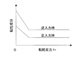
同操舵反力制御部の制御例における正入力時の転舵反力と摩擦成分の関係を示すグラフである。
同操舵反力制御部の制御例における転舵反力と粘性成分の関係を示すグラフである。
The present invention will be more clearly understood from the following description of preferred embodiments with reference to the accompanying drawings. However, the embodiments and drawings are for illustration and description only and should not be used to define the scope of the present invention. The scope of the invention is defined by the appended claims. In the accompanying drawings, the same reference numerals in a plurality of drawings indicate the same or corresponding parts.
It is explanatory drawing which shows schematic structure of the steer-by-wire type steering apparatus provided with the steering reaction force control apparatus which concerns on one Embodiment of this invention, and the conceptual structure of the control system. It is a block diagram which shows the conceptual structure of the steering reaction force control part in the steering reaction force control apparatus of the steer-by-wire. It is a flowchart which shows the flow of a process of the steering reaction force control part. It is a graph which shows the relationship between the steering reaction force at the time of positive input in the example of control of the steering reaction force control part, and a friction component. It is a graph which shows the relationship between the steering reaction force and the viscosity component in the control example of the steering reaction force control unit.
この発明の一実施形態を図1ないし図5と共に説明する。図1は、この実施形態に係る操舵反力制御装置を備えたステアバイワイヤ式操舵装置のシステム構成図である。操舵機構1は、転舵用のタイロッド間シャフト2と機械的に連結されていないステアリングホイール3に対して、操舵反力を生成する操舵反力モータ4と、操舵角度を検出する操舵角センサ5を備える。転舵機構6は、タイロッド間シャフト2を車幅方向に進退駆動する転舵モータ7とタイロッド間シャフト位置2の転舵変位量となる進退位置を検出する位置センサ8を備える。この他に転舵モータ7のトルクを検出する電流計等のトルク検出手段9と、転舵モータ7の回転角度を検出する回転角度検出手段10とが設けられている。
An embodiment of the present invention will be described with reference to FIGS. FIG. 1 is a system configuration diagram of a steer-by-wire type steering apparatus provided with a steering reaction force control apparatus according to this embodiment. The steering mechanism 1 includes a steering reaction force motor 4 that generates a steering reaction force against a steering wheel 3 that is not mechanically connected to the shaft 2 between tie rods for steering, and a steering angle sensor 5 that detects a steering angle. Is provided. The steering mechanism 6 includes a steering motor 7 that drives the shaft 2 between tie rods to advance and retreat in the vehicle width direction, and a position sensor 8 that detects an advancing / retreating position as a steering displacement amount of the shaft position 2 between the tie rods. In addition, torque detecting means 9 such as an ammeter for detecting the torque of the turning motor 7 and a rotation angle detecting means 10 for detecting the rotation angle of the turning motor 7 are provided.
ステアリング制御手段12は、自動車の全体を制御するECU(電気制御ユニット)11に設けられており、転舵制御部13と操舵反力制御部14とを有している。ECU11は、コンピュータとこれに実行されるプログラム、および電子回路により構成される。転舵制御部13は、操舵角センサ5の検出した操舵角を基に、車両に装備された他のセンサ類15からの運転状態検出信号と合わせて転舵角の指令信号を生成し、転舵機構6の転舵モータ7を制御する手段である。前記他のセンサ類15は、例えば、車速センサや、各車輪16に作用する荷重を検出センサ等である。他のセンサ類15は、一つであっても複数であっても良いが、ここでは、1つで代表して図示している。
The steering control means 12 is provided in an ECU (electric control unit) 11 that controls the entire vehicle, and includes a steering control unit 13 and a steering reaction force control unit 14. The ECU 11 includes a computer, a program executed on the computer, and an electronic circuit. Based on the steering angle detected by the steering angle sensor 5, the steering control unit 13 generates a steering angle command signal together with driving state detection signals from other sensors 15 mounted on the vehicle. It is means for controlling the steering motor 7 of the rudder mechanism 6. The other sensors 15 are, for example, a vehicle speed sensor or a sensor that detects a load acting on each wheel 16. The other sensors 15 may be one or plural, but here, one sensor 15 is shown as a representative.
操舵反力制御部14の具体例を図2に示す。操舵反力制御部14は、基本的には、操舵反力目標値演算部17により操舵反力目標値Paを、定められた規則によって演算し、操舵反力モータ4のモータ制御回路(図示せず)に出力する手段である。この基本構成において、操舵目標値演算部17による演算を行うにつき、操舵方向と転舵反力の方向とが異なる場合には正入力、同方向の場合には逆入力と判定し、この正逆に応じて操舵反力モータ4の操舵反力を制御するように構成している。
A specific example of the steering reaction force control unit 14 is shown in FIG. The steering reaction force control unit 14 basically calculates a steering reaction force target value Pa by a steering reaction force target value calculation unit 17 according to a predetermined rule, and a motor control circuit (not shown) of the steering reaction force motor 4. 2). In this basic configuration, when the calculation by the steering target value calculation unit 17 is performed, when the steering direction and the direction of the steering reaction force are different, it is determined that the input is normal, and when the direction is the same, the reverse input is determined. Accordingly, the steering reaction force of the steering reaction force motor 4 is controlled.
具体的には、前記転舵機構6(図1)に作用する転舵反力を検出する転舵反力検出手段18と、操舵方向を検出する操舵方向検出手段19とを設ける。操舵方向検出手段19は、前記操舵角センサ5、または転舵機構6の位置センサ8である。
Specifically, a turning reaction force detecting means 18 for detecting a turning reaction force acting on the turning mechanism 6 (FIG. 1) and a steering direction detecting means 19 for detecting a steering direction are provided. The steering direction detection means 19 is the steering angle sensor 5 or the position sensor 8 of the steering mechanism 6.
操舵反力制御部14は、操舵反力目標値演算部17と、入力正逆判定部21と、正逆対応処理部22とを有する。操舵反力目標値演算部17は、定められた規則に従って操舵モータ4の操舵反力の目標値Paを演算する手段である。入力正逆判定部21は、操舵方向検出手段19で検出される操舵方向が、転舵反力検出手段18で検出される転舵反力の方向と異なる場合には正入力、同方向の場合には逆入力と判定する手段である。正逆対応処理部22は、入力正逆判定部21の判定結果となる正逆に応じて、操舵反力目標値演算部17による演算内容を変更する手段である。
The steering reaction force control unit 14 includes a steering reaction force target value calculation unit 17, an input normal / reverse determination unit 21, and a normal / reverse correspondence processing unit 22. The steering reaction force target value calculation unit 17 is a means for calculating the target value Pa of the steering reaction force of the steering motor 4 according to a predetermined rule. When the steering direction detected by the steering direction detection means 19 is different from the direction of the steering reaction force detected by the steering reaction force detection means 18, the input normal / reverse determination unit 21 is a normal input and the same direction. Is a means for determining reverse input. The forward / reverse response processing unit 22 is means for changing the calculation content by the steering reaction force target value calculation unit 17 in accordance with the normal / reverse which is the determination result of the input normal / reverse determination unit 21.
転舵反力検出手段18は、転舵モータのトルク及び転舵変位量から、定められた推定式、例えば次式(1)に従って転舵反力Fhを推定するものである。この式(1)は、転舵反力Fhを、転舵モータ7の発生トルクTm、転舵速度(転舵モータ回転角度θの微分値)、および転舵加速度(転舵モータ回転角度θの2回微分値)から算出する式である。

The turning reaction force detection means 18 estimates the turning reaction force F h from the torque of the turning motor and the amount of turning displacement according to a predetermined estimation equation, for example, the following equation (1). The equation (1) is a turning reaction force F h, the generated torque T m of a turning motor 7, the steering speed (differential value of the steering motor rotation angle theta), and the steering acceleration (steering motor rotation angle This is a formula calculated from the twice differential value of θ.
なお、Ff:転舵機構摩擦成分
A,I,c:係数、
である。 F f : Steering mechanism friction component
A, I, c: coefficients
It is.
A,I,c:係数、
である。 F f : Steering mechanism friction component
A, I, c: coefficients
It is.
転舵モータ7の発生トルクTmは、転舵モータ7の前記トルク検出手段9から得られ、転舵モータ7の回転角度θは、前記回転角度検出手段10から得られる。トルク検出手段9で検出したトルクTmは、ローパスフィルタ23を通し、高周波成分を除去して転舵反力検出手段18に入力されるようにしている。転舵モータトルクTmに高周波成分が含まれていない場合は、ローパスフィルタ23は不要である。
The generated torque T m of the steered motor 7 is obtained from the torque detecting means 9 of the steered motor 7, and the rotation angle θ of the steered motor 7 is obtained from the rotational angle detecting means 10. The torque T m detected by the torque detection means 9 is inputted to the turning reaction force detection means 18 through the low-pass filter 23 to remove high frequency components. If there are no high-frequency components in the steering motor torque T m, the low-pass filter 23 is not required.
上記正逆対応処理部22は、入力正逆判定部21で判定された正入力または逆入力によって、前記推定式(1)における転舵反力Fhを推定する係数A、I、c,Ffを、定められた規則(図示せず)により変更する機能を有する。この係数の変更は、係数A、I、c,Ffのいずれか一つを変更するものであっても良く、また任意の2つ、または全てを変更するものであっても良い。
The positive inverse correspondence processing unit 22, the positive input or reverse input, which is determined by the input normal and reverse determination unit 21, the coefficient estimates the turning reaction force F h on the estimate equation (1) A, I, c , F It has a function of changing f according to a predetermined rule (not shown). The change of the coefficient may be to change any one of the coefficients A, I, c, and F f , or to change any two or all of them.
前記操舵反力目標値演算部17は、暫定操舵反力目標値演算部24と、別項加算部25とを有し、暫定操舵反力目標値演算部24で計算した暫定操舵反力目標値Paaに、別項加算部25によって後述の別項を加算して操舵反力目標値Paとする。
The steering reaction force target value calculation unit 17 includes a provisional steering reaction force target value calculation unit 24 and a separate addition unit 25, and the provisional steering reaction force target value Paa calculated by the provisional steering reaction force target value calculation unit 24. In addition, a separate item, which will be described later, is added by a separate item adding unit 25 to obtain a steering reaction force target value Pa.
暫定操舵反力目標値演算部24は、カットオフ周波数の変更可能なローパスフィルタ26を有していて、転舵反力検出手段18で検出された転舵反力(転舵反力推定値)Fhをローパスフィルタ26に通して得られた転舵反力を、目標操舵反力Paの基本値、すなわち暫定操舵反力目標値Paaとする。
The provisional steering reaction force target value calculation unit 24 has a low-pass filter 26 whose cutoff frequency can be changed, and the turning reaction force detected by the turning reaction force detection means 18 (the turning reaction force estimated value). the turning reaction force obtained through F h to the low pass filter 26, the basic value of the target steering reaction force Pa, i.e. a provisional steering reaction force target value Paa.
なお、転舵反力検出手段18による式(1)の演算は1kHz(1msec周期)で演算しており、その結果(デジタル信号波形)が、カットオフ周波数可変のローパスフィルタ26(カットオフ周波数は30Hz~0.5Hz程度)に入力される。前記ローパスフィルタ23もソフトウェアによるデジタルフィルタである。これらの演算には例えばSHマイコンを用いる。
The calculation of the formula (1) by the turning reaction force detection means 18 is performed at 1 kHz (1 msec cycle), and the result (digital signal waveform) is a low-pass filter 26 with a variable cut-off frequency (the cut-off frequency is (30Hz to about 0.5Hz). The low-pass filter 23 is also a software digital filter. For these calculations, for example, an SH microcomputer is used.
前記カットオフ周波数可変のローパスフィルタ26のカットオフ周波数は、一定でも良いが、転舵反力Fhが大きい時には高く、小さい時には低く設定されているのが良い。例えば、ローパスフィルタ26に、入力される転舵反力Fhを監視して、転舵反力Fhが大きい時には高く、小さい時には低くカットオフ周波数を変更するカットオフ周波数変更手段27が設けられている。この変更は、連続的であっても、段階的であっても良い。
Cut-off frequency of said variable cutoff frequency of the low pass filter 26 may be a constant, but higher when turning reaction force F h is large, it is preferable is set low when small. For example, the low-pass filter 26 is provided with a cut-off frequency changing means 27 that monitors the input turning reaction force F h and changes the cut-off frequency when the turning reaction force F h is high and low when the turning reaction force F h is small. ing. This change may be continuous or gradual.
カットオフ周波数変更手段27は、前記ローパスフィルタ26のカットオフ周波数を、切替え操作手段28からの入力で変更可能なものとしても良い。切替え操作手段28は、例えば、車両のコンソールやECUの外装面等に設けられる。カットオフ周波数変更手段27は、カットオフ周波数を、切替え操作手段28からの入力で変更可能で、かつその変更したカットオフ周波数を、さらに、入力される転舵反力Fhによって上記のように変更するものとしてもよい。
The cutoff frequency changing unit 27 may change the cutoff frequency of the low-pass filter 26 by an input from the switching operation unit 28. The switching operation means 28 is provided on, for example, a vehicle console or an exterior surface of an ECU. Cut-off frequency changing unit 27, a cut-off frequency, the switching can be changed by an input from the operation unit 28, and a cut-off frequency changing its further as described above by turning reaction force F h input It may be changed.
別項加算部25は、暫定操舵反力目標値演算部24の計算した暫定操舵反力目標値Paaに、摩擦項、粘性項、および慣性項を加え、操舵反力目標値Paを生成する。別項加算部25によるこれら摩擦項、粘性項、および慣性項の加算は、入力正逆判定部21の正逆の判定結果に応じて、正逆対応処理部22に変更される。変更内容については、後に全体の動作の説明と共に説明する。
The separate item adding unit 25 adds the friction term, the viscosity term, and the inertia term to the provisional steering reaction force target value Paa calculated by the provisional steering reaction force target value calculation unit 24 to generate a steering reaction force target value Pa. The addition of the friction term, the viscosity term, and the inertia term by the separate term adding unit 25 is changed to the normal / reverse correspondence processing unit 22 according to the normal / reverse determination result of the input normal / reverse determination unit 21. The details of the change will be described later together with an explanation of the overall operation.
上記構成の動作を説明する。図3は操舵反力目標値Paを演算するフローチャートである。まず、ステップS1の信号読み込み過程として、操舵方向を図2の操舵方向検出手段19により検出し、入力正逆判定部21に読み込む。操舵方向検出手段19は、前述のように、操舵機構1の操舵角センサ5または転舵機構6の位置センサ8であり、いずれで操舵方向を検出するようにしても良い。
The operation of the above configuration will be described. FIG. 3 is a flowchart for calculating the steering reaction force target value Pa. First, as a signal reading process in step S1, the steering direction is detected by the steering direction detecting means 19 shown in FIG. As described above, the steering direction detection means 19 is the steering angle sensor 5 of the steering mechanism 1 or the position sensor 8 of the steering mechanism 6, and any of the steering direction detection means 19 may detect the steering direction.
また、転舵モータ7の発生トルクTmをトルク検出手段9で検出し、かつ転舵速度および転舵加速度を回転検出手段10で検出して転舵反力検出手段18に読み込む。転舵モータトルクTmに高周波の成分が含まれている場合は、ローパスフィルタ23を通すことで、高周波成分が除去される(ステップS2)。転舵速度は転舵モータ回転角度θの微分値であり、転舵加速度は転舵モータ回転角度θの2回微分値であり、回転検出手段10からは転舵モータ回転角度θを読み込んで、転舵反力検出手段18より、転舵モータ回転角度θから転舵速度および転舵加速度を計算する。
Further, the steering torque generated T m of a motor 7 is detected by the torque detection unit 9, and detects the steering speed and steering acceleration in the rotation detecting means 10 reads the turning reaction force detecting means 18. If it contains high frequency components in the steering motor torque T m, is passed through a low-pass filter 23, high frequency components are removed (step S2). The turning speed is a differential value of the turning motor rotation angle θ, the turning acceleration is a twice differential value of the turning motor rotation angle θ, and the turning detection unit 10 reads the turning motor rotation angle θ. The turning reaction force detecting means 18 calculates the turning speed and turning acceleration from the turning motor rotation angle θ.
転舵反力検出手段18は、このように求められた発生トルクTm、転舵速度(転舵モータ回転角度θの微分値)、および転舵加速度(転舵モータ回転角度θの2回微分値)から、前述の次式(1)に従って、転舵反力Fhを算出する(ステップS3)。この算出値が、転舵反力の推定値である。
The turning reaction force detection means 18 generates the generated torque T m , the turning speed (the differential value of the turning motor rotation angle θ), and the turning acceleration (the second derivative of the turning motor rotation angle θ). from the value), according to the following equation (1) described above, calculates the turning reaction force F h (step S3). This calculated value is an estimated value of the steering reaction force.
転舵機構6の正入力と逆入力における伝達効率が異なる場合には、式(1)の係数A,I,c,Ffの値を、転舵機構6の正入力または逆入力によって変更することで転舵反力Fhを精度良く推定することができる。
When the transmission efficiency between the positive input and the reverse input of the steered mechanism 6 is different, the values of the coefficients A, I, c, and F f in the formula (1) are changed by the positive input or the reverse input of the steered mechanism 6. the turning reaction force F h can be accurately estimated by.
入力正逆判定部21は、操舵方向検出手段19で検出される操舵方向と転舵反力検出手段18で検出される転舵反力とによって、入力の正逆を判定する(ステップS4)。入力正逆判定部21において、転舵機構6にかかる入力は、操舵方向と推定転舵反力の方向が異なる場合には正入力、同方向の場合には逆入力と判定する。操舵角速度が0の場合には逆入力とする。
The input normal / reverse determination unit 21 determines whether the input is normal or reverse based on the steering direction detected by the steering direction detection means 19 and the turning reaction force detected by the turning reaction force detection means 18 (step S4). The input forward / reverse determination unit 21 determines that the input to the steering mechanism 6 is a positive input when the steering direction and the direction of the estimated steering reaction force are different, and a reverse input when the direction is the same. When the steering angular velocity is 0, the input is reversed.
操舵反力目標値演算部17の暫定操舵反力目標値演算部24は、転舵反力検出手段18で上記のように推定された転舵反力Fhを,カットオフ周波数を変更できるローパスフィルタ26に通し、暫定操舵反力目標値Paaを生成する(ステップS5)。このとき、カットオフ周波数変更手段27は、入力される推定転舵反力Fhが小さい場合にはカットオフ周波数を低くし、推定転舵反力が大きい場合にはカットオフ周波数を高くする。これにより、ステアリングホイール3の手放し時における振動を抑制できると共にクイックな操舵反力を得られる。推定転舵反力Fhが大きいか小さいかの基準、およびカットオフ周波数をどの値にするかは、シミュレーション等により任意に設計して定めれば良い。
The provisional steering reaction force target value calculation unit 24 of the steering reaction force target value calculation unit 17 is a low-pass capable of changing the cut-off frequency of the turning reaction force F h estimated by the turning reaction force detection means 18 as described above. The provisional steering reaction force target value Paa is generated through the filter 26 (step S5). At this time, the cut-off frequency changing unit 27 to lower the cutoff frequency when the estimated turning reaction force F h inputted is small, when the estimated turning reaction force is large to increase the cut-off frequency. Thereby, vibration at the time of releasing the steering wheel 3 can be suppressed, and a quick steering reaction force can be obtained. Estimated turning reaction force F h is greater than or less of criteria, and is either in which value the cut-off frequency, optionally may be determined by the design by simulation or the like.
また、カットオフ周波数変更手段27は、切替え操作手段28の操作によってカットオフ周波数を切り替え可能としてあり、この切り替えにより、ドライバーの好みに合わせて操舵フィーリングを変更できる。
Further, the cut-off frequency changing means 27 can change the cut-off frequency by the operation of the change-over operation means 28, and by this change, the steering feeling can be changed according to the preference of the driver.
別項加算部25は、上記のように計算された暫定操舵反力目標値Paaに、摩擦項、粘性項、および慣性項を加算し、操舵反力目標値Paを生成する(ステップS6)。

θSW:操舵角度(ステアリングホイール角度)
a:摩擦項
b:粘性項の係数
d:慣性項の係数
摩擦項、粘性項、および慣性項a,b,dは、適宜設定して定められる。 The separateitem adding unit 25 adds the friction term, the viscosity term, and the inertia term to the provisional steering reaction force target value Paa calculated as described above, and generates the steering reaction force target value Pa (step S6).
θ SW : Steering angle (steering wheel angle)
a: Friction term
b: Coefficient of viscosity term
d: Coefficient of inertia term The friction term, the viscosity term, and the inertia terms a, b, and d are appropriately set and determined.
a:摩擦項
b:粘性項の係数
d:慣性項の係数
摩擦項、粘性項、および慣性項a,b,dは、適宜設定して定められる。 The separate
a: Friction term
b: Coefficient of viscosity term
d: Coefficient of inertia term The friction term, the viscosity term, and the inertia terms a, b, and d are appropriately set and determined.
このとき、正逆対応処理部22は、別項加算部25の上記加算過程において、正入力の場合にのみ摩擦項(すなわち摩擦成分)を付与させる。これにより、ステアリングホイール3を中立位置から切り始めた際に、速やかに摩擦成分が付与され、操舵初期の操舵反力の手応え感を実現できる。逆入力の場合には摩擦成分を付与しないため、手放し時に於ける戻り位置のオフセットは生じない。
At this time, the forward / reverse correspondence processing unit 22 gives a friction term (that is, a friction component) only in the case of a positive input in the addition process of the separate item addition unit 25. As a result, when the steering wheel 3 starts to be turned from the neutral position, a friction component is quickly given, and a responsive feeling of the steering reaction force at the initial stage of steering can be realized. In the case of reverse input, no friction component is applied, so that there is no offset of the return position when releasing the hand.
別項加算部25において加算する摩擦成分、すなわち摩擦項の値aは、例えば図4に示すように、推定転舵反力Fhが大きいほど小さくし、ある閾値以上は0とする。このように設定すると、転舵反力Fhが小さい場合のみ摩擦成分を付与することが出来る。なお、同図のように変更せずに、摩擦項の値を一定としても良い。
For example, as shown in FIG. 4, the friction component to be added in the separate item adding unit 25, that is, the value “a” of the friction term is decreased as the estimated turning reaction force F h is increased, and is set to 0 above a certain threshold. With this setting, the turning reaction force F h is small only if it is possible to impart friction components. The value of the friction term may be constant without changing as shown in FIG.
また、正逆対応処理部22は、別項加算部25の上記加算過程において、逆入力の場合には粘性項の係数bを、正入力の場合より大きく設定する。粘性成分により手放し時の中立位置周りでの振動を抑えることができるとともに、正入力時の操舵反力が大きくなり過ぎる違和感を防ぐことができる。
Also, the forward / reverse correspondence processing unit 22 sets the coefficient b of the viscosity term larger in the case of reverse input than in the case of positive input in the addition process of the separate item addition unit 25. The viscous component can suppress vibration around the neutral position when letting go, and can prevent a sense of incongruity that the steering reaction force at the time of positive input becomes too large.
粘性項の係数bは、例えば図5に示すように、荷重つまり転舵反力Fhが大きいほど小さくしてもよい。このように設定すると、転舵反力Fhが小さい場合に大きな粘性成分を付与することが出来る。図5の例では、転舵反力Fhが0から一定の値までは、転舵反力Fhが大きくなるに従って粘性成分(粘性項の係数b)が小さくなるようにし、上記一定の値以上では一定となるように定めている。
Coefficient of viscosity term b, for example, as shown in FIG. 5 may be smaller the larger the load, i.e. the turning reaction force F h. With this setting, the turning reaction force F h it is possible to impart greater viscosity component is smaller. In the example of FIG. 5, when the turning reaction force F h is from 0 to a constant value, the viscosity component (viscosity coefficient b) decreases as the turning reaction force F h increases, and the above-described constant value is obtained. The above is determined to be constant.
この操舵反力制御装置によると、このように、ステアリングホイール3を中立位置から切り始めた際の良好な手応えを確保し、中立位置周りでの振動を防ぎつつ、手放し時における戻り位置を出来るだけ中立位置にするなどの利点が得られる。
According to this steering reaction force control device, as described above, a satisfactory response is obtained when the steering wheel 3 starts to be turned from the neutral position, and vibrations around the neutral position are prevented, and a return position when released is possible as much as possible. Advantages such as a neutral position can be obtained.
なお、上記実施形態では、転舵反力Fhを、転舵モータトルクなどから計算する転舵反力検出手段18により検出するようにしたが、上記転舵反力検出手段18を設ける代わりに、転舵機構6に備えたロードセルや荷重センサ等の転舵反力センサからなる転舵反力検出手段18Aにより、転舵反力Fhを検出するようにしても良い。その場合、このロードセルや荷重センサ等の転舵反力センサの検出した転舵反力Fhを、入力正逆判定部21による判定や、操舵反力目標値演算部17の暫定操舵目標値演算部24による暫定操舵反力目標値Paaや、操舵反力目標値Paの計算に用いる。
In the above embodiment, the turning reaction force F h is detected by the turning reaction force detection means 18 calculated from the turning motor torque or the like. Instead of providing the turning reaction force detection means 18, however. by turning reaction force detecting means 18A composed of a turning reaction force sensor load cell or the like load sensor provided in the steering mechanism 6, it may be detected the turning reaction force F h. In that case, the detected turning reaction force F h of the turning reaction force sensor such as the load cell and the load sensor, the input determination and by forward and reverse determination unit 21, provisional steering target value calculation of the steering reaction force target value computing section 17 This is used to calculate the provisional steering reaction force target value Paa and the steering reaction force target value Pa by the unit 24.
以上のとおり、図面を参照しながら好適な実施形態を説明したが、当業者であれば、本件明細書を見て、自明な範囲内で種々の変更および修正を容易に想定するであろう。したがって、そのような変更および修正は、請求の範囲から定まる発明の範囲内のものと解釈される。
As described above, the preferred embodiments have been described with reference to the drawings. However, those skilled in the art will readily assume various changes and modifications within the obvious scope by looking at the present specification. Accordingly, such changes and modifications are to be construed as within the scope of the invention as defined by the appended claims.
1…操舵機構
2…タイロッド間シャフト
3…ステアリングホイール
4…操舵反力モータ
5…操舵角センサ
6…転舵機構
7…転舵モータ
8…位置センサ
9…トルク検出手段
10…回転角度検出手段
12…ステアリング制御手段
13…転舵制御部
14…操舵反力制御部
15…他のセンサ類
17…操舵反力目標値演算部
18…転舵反力検出手段
18A…転舵反力検出手段
19…操舵方向検出手段
21…入力正逆判定部
22…正逆対応処理部
24…暫定操舵反力目標値演算部
25…別項加算部
26…カットオフ周波数可変のローパスフィルタ
27…カットオフ周波数変更手段
28…切替え操作手段 DESCRIPTION OF SYMBOLS 1 ... Steering mechanism 2 ... Shaft between tie rods 3 ...Steering wheel 4 ... Steering reaction force motor 5 ... Steering angle sensor 6 ... Steering mechanism 7 ... Steering motor 8 ... Position sensor 9 ... Torque detection means 10 ... Rotation angle detection means 12 ... Steering control means 13 ... Steering control part 14 ... Steering reaction force control part 15 ... Other sensors 17 ... Steering reaction force target value calculation part 18 ... Steering reaction force detection means 18A ... Steering reaction force detection means 19 ... Steering direction detection means 21 ... Input forward / reverse determination section 22 ... Forward / reverse correspondence processing section 24 ... Temporary steering reaction force target value calculation section 25 ... Additional item addition section 26 ... Cut-off frequency variable low-pass filter 27 ... Cut-off frequency change means 28 ... Switching operation means
2…タイロッド間シャフト
3…ステアリングホイール
4…操舵反力モータ
5…操舵角センサ
6…転舵機構
7…転舵モータ
8…位置センサ
9…トルク検出手段
10…回転角度検出手段
12…ステアリング制御手段
13…転舵制御部
14…操舵反力制御部
15…他のセンサ類
17…操舵反力目標値演算部
18…転舵反力検出手段
18A…転舵反力検出手段
19…操舵方向検出手段
21…入力正逆判定部
22…正逆対応処理部
24…暫定操舵反力目標値演算部
25…別項加算部
26…カットオフ周波数可変のローパスフィルタ
27…カットオフ周波数変更手段
28…切替え操作手段 DESCRIPTION OF SYMBOLS 1 ... Steering mechanism 2 ... Shaft between tie rods 3 ...
Claims (11)
- 転舵用のタイロッド間シャフトと機械的に連結されていないステアリングホイールに対し、操舵角を検出する操舵角センサと、操舵反力を与える操舵反力モータとが設けられ、前記操舵角センサの検出した操舵角を基に、車両に装備された他のセンサ類からの運転状態検出信号と合わせて転舵角の指令信号を生成し、タイロッド間シャフトを駆動する転舵機構の転舵モータを制御するステアリング制御手段を有するステアバイワイヤ式操舵装置であって、
操舵方向と転舵反力の方向とが異なる場合には正入力、同方向の場合には逆入力と判定し、この正逆に応じて前記操舵反力モータの操舵反力を制御する操舵反力制御部を設けたステアバイワイヤの操舵反力制御装置。 A steering angle sensor that detects a steering angle and a steering reaction force motor that applies a steering reaction force to a steering wheel that is not mechanically connected to the shaft between the tie rods for turning are provided. Based on the steered steering angle, it generates a steering angle command signal together with driving state detection signals from other sensors mounted on the vehicle, and controls the steering motor of the steering mechanism that drives the shaft between the tie rods A steer-by-wire steering device having steering control means for
When the steering direction and the direction of the steering reaction force are different, it is determined that the input is a positive input, and when the direction is the same, a reverse input is determined. Steer-by-wire steering reaction force control device provided with a force control unit. - 請求項1において、前記転舵機構に作用する転舵反力を検出する転舵反力検出手段と、操舵方向を検出する操舵方向検出手段とを設け、前記操舵反力制御部は、定められた規則に従って前記操舵モータの操舵反力の目標値を演算する操舵目標値演算部と、前記操舵方向検出手段で検出される操舵方向が前記転舵反力検出手段で検出される転舵反力の方向と異なる場合には正入力、同方向の場合には逆入力と判定する入力正逆判定部と、前記入力正逆判定部の判定結果となる正逆に応じて前記操舵目標値演算部による演算内容を変更する正逆対応処理部とを有するステアバイワイヤの操舵反力制御装置。 2. The steering reaction force detecting means for detecting a steering reaction force acting on the steering mechanism and a steering direction detecting means for detecting a steering direction are provided, and the steering reaction force control unit is defined. A steering target value calculation unit for calculating a target value of the steering reaction force of the steering motor according to the rules, and a steering reaction force in which the steering direction detected by the steering direction detection means is detected by the steering reaction force detection means An input forward / reverse determination unit that determines a positive input when the direction is different, and a reverse input when the direction is the same, and the steering target value calculation unit according to the forward or reverse that is the determination result of the input forward / reverse determination unit A steer-by-wire steering reaction force control device having a forward / reverse response processing unit for changing the calculation content of the control.
- 請求項2において、前記操舵方向検出手段が前記操舵角センサであるステアバイワイヤの操舵反力制御装置。 The steer-by-wire steering reaction force control device according to claim 2, wherein the steering direction detection means is the steering angle sensor.
- 請求項2において、前記転舵反力検出手段が、転舵モータのトルク及び転舵変位量から、定められた推定式に従って転舵反力を推定するものであり、前記正逆対応処理部は、前記入力正逆判定部で判定された正入力または逆入力によって、前記推定式における転舵反力を推定する係数を変更する機能を有するステアバイワイヤの操舵反力制御装置。 In Claim 2, the said steering reaction force detection means estimates a steering reaction force from the torque of a steering motor, and a steering displacement amount according to the defined estimation formula, The said normal / reverse correspondence processing part is A steer-by-wire steering reaction force control device having a function of changing a coefficient for estimating the turning reaction force in the estimation equation based on the normal input or the reverse input determined by the input normal / reverse determination unit.
- 請求項4において、前記転舵反力検出手段で検出された転舵反力の検出信号を通過させるフィルタとして、カットオフ周波数の変更可能なローパスフィルタを設け、このローパスフィルタ通して得られた転舵反力を、前記操舵目標値演算部は目標操舵反力の基本値とするステアバイワイヤの操舵反力制御装置。 5. A low-pass filter capable of changing a cutoff frequency is provided as a filter that allows a steering reaction force detection signal detected by the steering reaction force detection means to pass therethrough. A steer-by-wire steering reaction force control device in which the steering reaction value is set to a basic value of the target steering reaction force.
- 請求項5において、前記ローパスフィルタのカットオフ周波数は、転舵反力が大きい時には高く、小さい時には低く設定されたステアバイワイヤの操舵反力制御装置。 6. The steer-by-wire steering reaction force control device according to claim 5, wherein the cut-off frequency of the low-pass filter is set high when the steering reaction force is large and low when the steering reaction force is small.
- 請求項5において、前記ローパスフィルタのカットオフ周波数を、切替え操作手段からの入力で変更することにより、ドライバーの好みに合わせて操舵フィーリングを変更できるようにするカットオフ周波数変更手段を設けたステアバイワイヤの操舵反力制御装置。 6. The steering system according to claim 5, further comprising: a cut-off frequency changing unit that changes a cut-off frequency of the low-pass filter by an input from the switching operation unit so that the steering feeling can be changed in accordance with a driver's preference. By-wire steering reaction force control device.
- 請求項2において、前記操舵反力制御部は、前記入力正逆判定部の判定結果が正入力の場合には操舵反力目標値に摩擦成分を付与し、逆入力の場合には付与しないものとしたステアバイワイヤの操舵反力制御装置。 3. The steering reaction force control unit according to claim 2, wherein the steering reaction force control unit applies a friction component to the steering reaction force target value when the determination result of the input normal / reverse determination unit is a positive input, and does not apply it when the input is a reverse input. Steer-by-wire steering reaction force control device.
- 請求項8において、前記操舵反力制御部は、転舵反力が大きいほど前記摩擦成分を小さく設定したものであるステアバイワイヤの操舵反力制御装置。 9. The steer-by-wire steering reaction force control device according to claim 8, wherein the steering reaction force control unit sets the friction component to be smaller as the turning reaction force is larger.
- 請求項2において、前記操舵反力制御部は、操舵反力目標値に加える粘性項の係数が、前記入力正逆判定部の判定結果が逆入力の場合に、正入力の場合より大きい値に設定されたステアバイワイヤの操舵反力制御装置。 The steering reaction force control unit according to claim 2, wherein the coefficient of the viscosity term added to the steering reaction force target value is set to a larger value when the determination result of the input forward / reverse determination unit is a reverse input than when the input is a positive input. Steering-by-wire steering reaction force control device.
- 請求項10において、前記操舵反力制御部は、転舵反力が大きいほど前記粘性項の係数が小さく設定されたステアバイワイヤの操舵反力制御装置。 11. The steer-by-wire steering reaction force control device according to claim 10, wherein the steering reaction force control unit has a coefficient of the viscosity term set to be smaller as a turning reaction force is larger.
Applications Claiming Priority (2)
| Application Number | Priority Date | Filing Date | Title |
|---|---|---|---|
| JP2010282595A JP5697966B2 (en) | 2010-12-20 | 2010-12-20 | Steer-by-wire steering reaction force control device |
| JP2010-282595 | 2010-12-20 |
Publications (1)
| Publication Number | Publication Date |
|---|---|
| WO2012086502A1 true WO2012086502A1 (en) | 2012-06-28 |
Family
ID=46313778
Family Applications (1)
| Application Number | Title | Priority Date | Filing Date |
|---|---|---|---|
| PCT/JP2011/078993 WO2012086502A1 (en) | 2010-12-20 | 2011-12-15 | Steering reaction force control device for steer-by-wire |
Country Status (2)
| Country | Link |
|---|---|
| JP (1) | JP5697966B2 (en) |
| WO (1) | WO2012086502A1 (en) |
Cited By (4)
| Publication number | Priority date | Publication date | Assignee | Title |
|---|---|---|---|---|
| EP2610131A1 (en) * | 2011-12-26 | 2013-07-03 | Jtekt Corporation | Steering system |
| CN109552401A (en) * | 2017-09-27 | 2019-04-02 | 株式会社捷太格特 | Vehicle console device |
| US10336344B2 (en) | 2016-02-16 | 2019-07-02 | Toyota Jidosha Kabushiki Kaisha | Vehicle control apparatus |
| CN112566835A (en) * | 2018-08-08 | 2021-03-26 | 日产自动车株式会社 | Steering control method and steering control device |
Families Citing this family (2)
| Publication number | Priority date | Publication date | Assignee | Title |
|---|---|---|---|---|
| US11046359B2 (en) | 2017-09-25 | 2021-06-29 | Mando Corporation | Steer-by-wire system and control method thereof |
| KR102004348B1 (en) * | 2017-09-29 | 2019-07-29 | 주식회사 만도 | Methods for generating steering wheel reaction in Steer-by-wire system and apparatuses thereof |
Citations (7)
| Publication number | Priority date | Publication date | Assignee | Title |
|---|---|---|---|---|
| JP2002029441A (en) * | 2000-07-19 | 2002-01-29 | Mitsubishi Electric Corp | Control device for electric power steering system |
| JP2005335613A (en) * | 2004-05-28 | 2005-12-08 | Mitsubishi Electric Corp | Steering gear for vehicle |
| JP2006069351A (en) * | 2004-09-01 | 2006-03-16 | Toyota Motor Corp | Steering device for vehicle |
| JP2007090924A (en) * | 2005-09-27 | 2007-04-12 | Toyota Motor Corp | Steering device for vehicle |
| JP2007137287A (en) * | 2005-11-18 | 2007-06-07 | Toyota Motor Corp | Steering device of vehicle |
| JP2008024092A (en) * | 2006-07-19 | 2008-02-07 | Toyota Motor Corp | Steering device of vehicle |
| JP2010168008A (en) * | 2009-01-26 | 2010-08-05 | Nissan Motor Co Ltd | Steering device and steering control method |
-
2010
- 2010-12-20 JP JP2010282595A patent/JP5697966B2/en not_active Expired - Fee Related
-
2011
- 2011-12-15 WO PCT/JP2011/078993 patent/WO2012086502A1/en active Application Filing
Patent Citations (7)
| Publication number | Priority date | Publication date | Assignee | Title |
|---|---|---|---|---|
| JP2002029441A (en) * | 2000-07-19 | 2002-01-29 | Mitsubishi Electric Corp | Control device for electric power steering system |
| JP2005335613A (en) * | 2004-05-28 | 2005-12-08 | Mitsubishi Electric Corp | Steering gear for vehicle |
| JP2006069351A (en) * | 2004-09-01 | 2006-03-16 | Toyota Motor Corp | Steering device for vehicle |
| JP2007090924A (en) * | 2005-09-27 | 2007-04-12 | Toyota Motor Corp | Steering device for vehicle |
| JP2007137287A (en) * | 2005-11-18 | 2007-06-07 | Toyota Motor Corp | Steering device of vehicle |
| JP2008024092A (en) * | 2006-07-19 | 2008-02-07 | Toyota Motor Corp | Steering device of vehicle |
| JP2010168008A (en) * | 2009-01-26 | 2010-08-05 | Nissan Motor Co Ltd | Steering device and steering control method |
Cited By (7)
| Publication number | Priority date | Publication date | Assignee | Title |
|---|---|---|---|---|
| EP2610131A1 (en) * | 2011-12-26 | 2013-07-03 | Jtekt Corporation | Steering system |
| US8662240B2 (en) | 2011-12-26 | 2014-03-04 | Jtekt Corporation | Steering system |
| US10336344B2 (en) | 2016-02-16 | 2019-07-02 | Toyota Jidosha Kabushiki Kaisha | Vehicle control apparatus |
| CN109552401A (en) * | 2017-09-27 | 2019-04-02 | 株式会社捷太格特 | Vehicle console device |
| CN112566835A (en) * | 2018-08-08 | 2021-03-26 | 日产自动车株式会社 | Steering control method and steering control device |
| CN112566835B (en) * | 2018-08-08 | 2023-01-10 | 日产自动车株式会社 | Steering control method and steering control device |
| US11603128B2 (en) | 2018-08-08 | 2023-03-14 | Nissan Motor Co., Ltd. | Steering control method and steering control device |
Also Published As
| Publication number | Publication date |
|---|---|
| JP5697966B2 (en) | 2015-04-08 |
| JP2012131246A (en) | 2012-07-12 |
Similar Documents
| Publication | Publication Date | Title |
|---|---|---|
| JP4984110B2 (en) | Electric power steering device | |
| EP1837266B1 (en) | Electric power steering device controller | |
| JP5109342B2 (en) | Electric power steering device | |
| JP4561806B2 (en) | Electric power steering device | |
| WO2012086502A1 (en) | Steering reaction force control device for steer-by-wire | |
| JP5313729B2 (en) | Electric power steering device | |
| JP4380697B2 (en) | Vehicle steering control device | |
| WO2012014399A1 (en) | Electric power steering device | |
| JP2007125973A (en) | Vehicular steering device | |
| JP2006199219A (en) | Control device of electric power steering device | |
| JP4581694B2 (en) | Control device for electric power steering device | |
| JP2008018825A (en) | Control device for electric power steering device | |
| JP4530880B2 (en) | Vehicle motion state control device | |
| JP2009023608A (en) | Vehicle steering apparatus | |
| JP5140158B2 (en) | Electric power steering control device | |
| JP2006137215A (en) | Steering reaction force control device of steer by wire type steering device | |
| JP4404693B2 (en) | Vehicle steering system | |
| JP4906333B2 (en) | Vehicle steering device | |
| JP4815958B2 (en) | Electric power steering device | |
| JP2008062837A (en) | Steering control device for vehicle | |
| JP4011424B2 (en) | Steering control device | |
| JP5844861B2 (en) | Steer-by-wire steering reaction force control device | |
| JP5772344B2 (en) | Vehicle steering system | |
| KR100795102B1 (en) | A return control apparatus of eps system | |
| JP2006175981A (en) | Steering control device |
Legal Events
| Date | Code | Title | Description |
|---|---|---|---|
| 121 | Ep: the epo has been informed by wipo that ep was designated in this application |
Ref document number: 11851165 Country of ref document: EP Kind code of ref document: A1 |
|
| NENP | Non-entry into the national phase |
Ref country code: DE |
|
| 122 | Ep: pct application non-entry in european phase |
Ref document number: 11851165 Country of ref document: EP Kind code of ref document: A1 |