WO2012081642A1 - 太陽熱集熱用反射板の表面塗布用塗料組成物および太陽熱集熱用反射板の製造方法 - Google Patents
太陽熱集熱用反射板の表面塗布用塗料組成物および太陽熱集熱用反射板の製造方法 Download PDFInfo
- Publication number
- WO2012081642A1 WO2012081642A1 PCT/JP2011/078964 JP2011078964W WO2012081642A1 WO 2012081642 A1 WO2012081642 A1 WO 2012081642A1 JP 2011078964 W JP2011078964 W JP 2011078964W WO 2012081642 A1 WO2012081642 A1 WO 2012081642A1
- Authority
- WO
- WIPO (PCT)
- Prior art keywords
- coating film
- coating
- solar heat
- coating composition
- heat collecting
- Prior art date
- Legal status (The legal status is an assumption and is not a legal conclusion. Google has not performed a legal analysis and makes no representation as to the accuracy of the status listed.)
- Ceased
Links
Images


Classifications
-
- C—CHEMISTRY; METALLURGY
- C09—DYES; PAINTS; POLISHES; NATURAL RESINS; ADHESIVES; COMPOSITIONS NOT OTHERWISE PROVIDED FOR; APPLICATIONS OF MATERIALS NOT OTHERWISE PROVIDED FOR
- C09D—COATING COMPOSITIONS, e.g. PAINTS, VARNISHES OR LACQUERS; FILLING PASTES; CHEMICAL PAINT OR INK REMOVERS; INKS; CORRECTING FLUIDS; WOODSTAINS; PASTES OR SOLIDS FOR COLOURING OR PRINTING; USE OF MATERIALS THEREFOR
- C09D127/00—Coating compositions based on homopolymers or copolymers of compounds having one or more unsaturated aliphatic radicals, each having only one carbon-to-carbon double bond, and at least one being terminated by a halogen; Coating compositions based on derivatives of such polymers
- C09D127/02—Coating compositions based on homopolymers or copolymers of compounds having one or more unsaturated aliphatic radicals, each having only one carbon-to-carbon double bond, and at least one being terminated by a halogen; Coating compositions based on derivatives of such polymers not modified by chemical after-treatment
- C09D127/12—Coating compositions based on homopolymers or copolymers of compounds having one or more unsaturated aliphatic radicals, each having only one carbon-to-carbon double bond, and at least one being terminated by a halogen; Coating compositions based on derivatives of such polymers not modified by chemical after-treatment containing fluorine atoms
-
- C—CHEMISTRY; METALLURGY
- C09—DYES; PAINTS; POLISHES; NATURAL RESINS; ADHESIVES; COMPOSITIONS NOT OTHERWISE PROVIDED FOR; APPLICATIONS OF MATERIALS NOT OTHERWISE PROVIDED FOR
- C09D—COATING COMPOSITIONS, e.g. PAINTS, VARNISHES OR LACQUERS; FILLING PASTES; CHEMICAL PAINT OR INK REMOVERS; INKS; CORRECTING FLUIDS; WOODSTAINS; PASTES OR SOLIDS FOR COLOURING OR PRINTING; USE OF MATERIALS THEREFOR
- C09D5/00—Coating compositions, e.g. paints, varnishes or lacquers, characterised by their physical nature or the effects produced; Filling pastes
- C09D5/02—Emulsion paints including aerosols
- C09D5/024—Emulsion paints including aerosols characterised by the additives
-
- F—MECHANICAL ENGINEERING; LIGHTING; HEATING; WEAPONS; BLASTING
- F24—HEATING; RANGES; VENTILATING
- F24S—SOLAR HEAT COLLECTORS; SOLAR HEAT SYSTEMS
- F24S23/00—Arrangements for concentrating solar-rays for solar heat collectors
- F24S23/70—Arrangements for concentrating solar-rays for solar heat collectors with reflectors
- F24S23/82—Arrangements for concentrating solar-rays for solar heat collectors with reflectors characterised by the material or the construction of the reflector
-
- C—CHEMISTRY; METALLURGY
- C08—ORGANIC MACROMOLECULAR COMPOUNDS; THEIR PREPARATION OR CHEMICAL WORKING-UP; COMPOSITIONS BASED THEREON
- C08K—Use of inorganic or non-macromolecular organic substances as compounding ingredients
- C08K5/00—Use of organic ingredients
- C08K5/0008—Organic ingredients according to more than one of the "one dot" groups of C08K5/01 - C08K5/59
- C08K5/0025—Crosslinking or vulcanising agents; including accelerators
-
- C—CHEMISTRY; METALLURGY
- C08—ORGANIC MACROMOLECULAR COMPOUNDS; THEIR PREPARATION OR CHEMICAL WORKING-UP; COMPOSITIONS BASED THEREON
- C08K—Use of inorganic or non-macromolecular organic substances as compounding ingredients
- C08K5/00—Use of organic ingredients
- C08K5/16—Nitrogen-containing compounds
- C08K5/29—Compounds containing one or more carbon-to-nitrogen double bonds
-
- F—MECHANICAL ENGINEERING; LIGHTING; HEATING; WEAPONS; BLASTING
- F24—HEATING; RANGES; VENTILATING
- F24S—SOLAR HEAT COLLECTORS; SOLAR HEAT SYSTEMS
- F24S23/00—Arrangements for concentrating solar-rays for solar heat collectors
- F24S23/70—Arrangements for concentrating solar-rays for solar heat collectors with reflectors
- F24S2023/86—Arrangements for concentrating solar-rays for solar heat collectors with reflectors in the form of reflective coatings
-
- Y—GENERAL TAGGING OF NEW TECHNOLOGICAL DEVELOPMENTS; GENERAL TAGGING OF CROSS-SECTIONAL TECHNOLOGIES SPANNING OVER SEVERAL SECTIONS OF THE IPC; TECHNICAL SUBJECTS COVERED BY FORMER USPC CROSS-REFERENCE ART COLLECTIONS [XRACs] AND DIGESTS
- Y02—TECHNOLOGIES OR APPLICATIONS FOR MITIGATION OR ADAPTATION AGAINST CLIMATE CHANGE
- Y02E—REDUCTION OF GREENHOUSE GAS [GHG] EMISSIONS, RELATED TO ENERGY GENERATION, TRANSMISSION OR DISTRIBUTION
- Y02E10/00—Energy generation through renewable energy sources
- Y02E10/40—Solar thermal energy, e.g. solar towers
Definitions
- the present invention relates to a coating composition for surface coating of a solar heat collecting reflector and a method for producing a solar heat collecting reflector.
- the solar heat collection system includes a solar heat collection system having a heat collection tube provided with a heat medium such as water or an inorganic salt, and a solar heat collection reflection plate that reflects sunlight and collects the heat collection tube. It is done.
- sunlight is reflected by a solar heat collecting reflector and collected in a heat collecting tube, and the heat medium of the heat collecting tube is heated by the sunlight to obtain thermal energy.
- a mirror having a coating film formed on a metal reflection layer of a reflection substrate comprising a glass substrate and a metal reflection layer formed on the glass substrate is widely used. Yes.
- a back coating film is formed on the reflective substrate on the opposite side of the metal reflective layer for the purpose of suppressing corrosion and alteration of the metal reflective layer.
- a rust preventive paint is used for forming the back coating film. Examples of the rust preventive paint include alkyd resin paint, epoxy resin paint, acrylic resin paint, polyester resin paint, and the like.
- a solar heat collecting reflector a reflector having a mirror-finished surface (reflecting surface) formed on the surface of a reflecting substrate made of a metal such as aluminum, aluminum alloy, or stainless steel is also widely used.
- a solar heat collecting reflector in which a coating film is formed by coating a tetrafluoroethylene-6fluoropropylene copolymer resin on a reflective substrate made of aluminum or an aluminum alloy is known (Patent Document 1). ).
- Patent Document 1 a solar heat collecting reflector in which a coating film is formed by coating a tetrafluoroethylene-6fluoropropylene copolymer resin on a reflective substrate made of aluminum or an aluminum alloy.
- the present invention provides a coating composition for surface coating of a solar heat collecting reflector, which is less susceptible to peeling and cracking even when used under severe conditions such as deserts, and can form a coating film having excellent weather resistance. With the goal.
- Another object of the present invention is to provide a method for producing a solar heat collecting reflector having a coating film having excellent weather resistance that hardly causes peeling or cracking even when used under severe conditions such as deserts. To do.
- a coating composition for surface coating of a solar heat collecting reflector comprising the following fluorinated copolymer (A), a curing agent (B) and a solvent (C).
- the curing agent (B) comprises a compound having 2 to 4 functional groups per molecule capable of reacting with a hydroxyl group of the fluorine-containing copolymer (A).
- a coating composition for surface coating of a reflector for heat is 20 to 80 mol% of a polymer unit (a-1) based on a fluoroolefin and a polymer unit (a-2) based on an unsaturated monomer having a hydroxyl group. ) Is 1 to 40 mol%, and the polymerized unit (a-3) based on the unsaturated monomer having an alkyl group having 6 to 16 carbon atoms is 1 to 60 mol%, and the hydroxyl value is 5 to 47 mgKOH / g.
- the coating composition for surface coating of a solar heat collecting reflector as described in [1] or [2], which is a resin.
- the curing agent (B) is represented by —X—C ( ⁇ O) —NH— (where X is an organic group derived from a compound having a hydroxyl group or a compound having an amino group).
- the coating composition for surface coating of a solar heat collecting reflector according to any one of [1] to [3], which is an isocyanate curing agent having a structure and an isocyanate group content of 5 to 35% by mass object.
- the coating layer A method for producing a solar heat collecting reflector, wherein the solvent (C) is removed from the substrate and cured to form a coating film.
- the physical properties of the coating film formed from the coating composition have an elongation of 10 to 200%, a glass transition temperature of 20 to 80 ° C., and a crosslinking density of 1.0 ⁇ 10 ⁇ 4 to 9.
- a coating layer is formed by coating the surface of the reflective substrate with the coating composition for surface coating of the solar heat collecting reflector according to any one of [1] to [4], A reflector for solar heat collection, characterized by having a coating film obtained by curing the material.
- the coating film has physical properties of an elongation of 10 to 200%, a glass transition temperature of 20 to 80 ° C., and a crosslinking density of 1.0 ⁇ 10 ⁇ 4 to 9.0 ⁇ 10 ⁇ 4 mol / cm 3 [7] ]
- the solar heat collecting reflector is
- the coating composition for surface coating of a solar heat collecting reflector according to the present invention can form a coating film that hardly peels off or cracks even when used under severe conditions such as deserts and has excellent weather resistance.
- the solar heat collecting material having a coating film excellent in weather resistance that hardly causes peeling or cracking. A reflector for heat is obtained.
- a general term includes a polymer unit directly formed by polymerizing monomers and a polymer unit obtained by chemically converting a part of the polymer units formed by monomer polymerization. This is called “unit”.
- (meth) acrylic acid indicates at least one of acrylic acid and methacrylic acid, and the same applies to (meth) acryloyl groups and (meth) acrylates.
- the coating composition for surface coating of the reflector for solar heat collection of the present invention (hereinafter also simply referred to as “coating composition”) comprises a fluorinated copolymer (A), a curing agent (B) and a solvent (described later). It is a coating composition containing C) as an essential component.
- the fluorine-containing copolymer (A) is a polymerized unit (a-1) based on a fluoroolefin (hereinafter also referred to simply as “unit (a-1)”), an unsaturated monomer having a hydroxyl group (hereinafter referred to as “unit”).
- unit (a-3) based on a monomer (hereinafter also referred to as “monomer ( ⁇ 3)”
- the fluorine-containing copolymer (A) reacts with the curing agent (B) described later to form a crosslinked structure and is cured to form a coating film.
- the unit (a-1) is a unit based on a fluoroolefin.
- a fluoroolefin is a compound in which one or more hydrogen atoms of an olefin hydrocarbon (general formula C n H 2n ) are substituted with a fluorine atom.
- the carbon number of the fluoroolefin is preferably 2 to 8, and more preferably 2 to 6.
- the number of fluorine atoms in the fluoroolefin (hereinafter referred to as “fluorine addition number”) is preferably 2 or more, and more preferably 3 to 4. When the fluorine addition number is 2 or more, the weather resistance of the formed coating film is improved.
- one or more hydrogen atoms not substituted with fluorine atoms may be substituted with chlorine atoms.
- the fluoroolefin one or more selected from the group consisting of tetrafluoroethylene, chlorotrifluoroethylene, hexafluoropropylene, vinylidene fluoride and vinyl fluoride is preferable, and tetrafluoroethylene and chlorotrifluoroethylene are more preferable.
- a fluoro olefin may be used individually by 1 type, and may use 2 or more types together.
- the unit (a-1) is preferably a polymer unit directly formed by polymerizing a fluoroolefin.
- the unit (a-2) is a unit based on an unsaturated monomer having a hydroxyl group (monomer ( ⁇ 2)).
- the unit (a-2) is preferably a unit directly formed by polymerizing the monomer ( ⁇ 2).
- the monomer ( ⁇ 2) is a monomer having a polymerizable reactive group and a hydroxyl group.
- the polymerizable reactive group is preferably an ethylenically unsaturated group such as a vinyl group, an allyl group, or a (meth) acryloyl group. That is, the monomer ( ⁇ 2) is preferably a monomer having a hydroxyl group and an ethylenically unsaturated group.
- the number of carbon atoms of the monomer ( ⁇ 2) is preferably 2 to 10, and more preferably 3 to 6.
- the monomer ( ⁇ 2) may have an ether bond, an ester bond, a urethane bond, or an amide bond between carbon-carbon bonds other than the double bond of the ethylenically unsaturated bond. Further, the monomer ( ⁇ 2) may be linear or branched.
- Examples of the monomer ( ⁇ 2) include 2-hydroxyethyl vinyl ether, 3-hydroxypropyl vinyl ether, 2-hydroxypropyl vinyl ether, 2-hydroxy-2-methylpropyl vinyl ether, 4-hydroxybutyl vinyl ether, 4-hydroxy-2 -Hydroxyalkyl vinyl ethers such as methylbutyl vinyl ether, 5-hydroxypentyl vinyl ether, 6-hydroxyhexyl vinyl ether; ethylene glycol monovinyl ethers such as diethylene glycol monovinyl ether, triethylene glycol monovinyl ether, tetraethylene glycol monovinyl ether; hydroxyethyl allyl ether , Hydroxybutyl allyl ether, 2-hydroxyethyl allyl ether, 4-hy Hydroxyalkyl allyl ethers such as loxybutyl allyl ether and glycerol monoallyl ether; Hydroxyalkyl vinyl esters such as hydroxyethyl vinyl ester and hydroxybuty
- hydroxyalkyl vinyl ethers and ethylene glycol monovinyl ethers are more preferable because they are excellent in alternating copolymerization with fluoroolefin and improve the weather resistance of the formed coating film. More preferred are hydroxyethyl vinyl ether, 4-hydroxybutyl vinyl ether, and diethylene glycol monovinyl ether.
- the unit (a-2) is formed by a method in which after polymerization is performed using a monomer having no hydroxyl group, a part of the polymerized unit of the obtained polymer is chemically converted to introduce a hydroxyl group. May be.
- a part of the polymerized unit of the obtained polymer is chemically converted to introduce a hydroxyl group.
- a part (functional group) may be formed by chemical conversion. Specific examples include a method in which a diol compound is reacted with the obtained polymer after polymerization using a monomer having a carboxyl group.
- the unit (a-2) may have another group such as an alkyl group in addition to the hydroxyl group.
- the unit (a-2) contained in the fluorinated copolymer (A) may be one type or two or more types.
- the unit (a-3) is a unit having no hydroxyl group other than the unit (a-1) and the unit (a-2), and an unsaturated monomer having a C 6-16 alkyl group (single monomer) A unit based on the body ( ⁇ 3)).
- the unit (a-3) is preferably a unit directly formed by polymerizing the monomer ( ⁇ 3).
- the monomer ( ⁇ 3) is a monomer having a polymerizable reactive group and an alkyl group having 6 to 16 carbon atoms.
- the ethylenically unsaturated group mentioned in the monomer ( ⁇ 2) is preferable.
- the alkyl group in the monomer ( ⁇ 3) may be linear or branched, and may partially have a cyclic structure.
- the number of carbon atoms of the alkyl group of the monomer ( ⁇ 3) is preferably 6 to 13, and more preferably 7 to 11.
- Examples of the monomer ( ⁇ 3) include monomers ( ⁇ 31) to ( ⁇ 34) shown below.
- Monomer ( ⁇ 31) Vinyl esters having an alkyl group having 6 to 16 carbon atoms.
- Monomer ( ⁇ 32) Vinyl ethers having an alkyl group having 6 to 16 carbon atoms.
- Monomer ( ⁇ 33) allyl ethers having an alkyl group having 6 to 16 carbon atoms.
- Examples of the monomer ( ⁇ 31) include vinyl decanoate and vinyl laurate.
- Examples of the monomer ( ⁇ 32) include 2-ethylhexyl vinyl ether, cyclohexyl vinyl ether, octyl vinyl ether, and the like.
- Examples of the monomer ( ⁇ 33) include cyclohexyl allyl ether and hexyl allyl ether.
- Examples of the monomer ( ⁇ 34) include octene and decene.
- a monomer ((alpha) 3) may be used individually by 1 type, and may use 2 or more types together.
- the monomer ( ⁇ 3) monomers ( ⁇ 31) to ( ⁇ 33) are preferable in terms of improving the adhesion between the coating film on the solar heat collecting reflector and the layer on which the coating film is formed, From the viewpoint of improving the solubility of the fluorinated copolymer (A) in the solvent (C), the monomer ( ⁇ 34) is preferred.
- the monomer ( ⁇ 3) the monomer ( ⁇ 32) is more preferable, and 2-ethylhexyl vinyl ether and cyclohexyl vinyl ether are particularly preferable from the viewpoint of easily forming a coating film in which peeling or cracking is unlikely to occur.
- the unit (a-3) was polymerized using a monomer having no alkyl group having 6 to 16 carbon atoms, and then a part of the polymerized unit of the obtained polymer was chemically converted to produce carbon. You may form by the method of introduce
- the unit (a-3) contained in the fluorinated copolymer (A) may be one type or two or more types.
- the fluorine-containing copolymer (A) in the present invention is represented by units (a-1), (a-2) and (a-3) (hereinafter also simply referred to as units (a-1) to (a-3)).
- the polymer unit (a-4) (hereinafter also simply referred to as “unit (a-4)”) is optionally included. May be.
- the unit (a-4) is a unit based on a fluoroolefin, a monomer ( ⁇ 2) and another monomer ( ⁇ 4) copolymerizable with the monomer ( ⁇ 3).
- the unit (a-4) is used as an adhesive between the coating film on the solar heat collecting reflector and the layer on which the coating film is formed.
- a unit (a-41) based on another monomer ( ⁇ 41) that exhibits an effect of improving the properties is preferred.
- vinyl esters, vinyl ethers and allyl ethers other than the monomers ( ⁇ 31) to ( ⁇ 33) are preferable.
- Specific examples include vinyl esters such as vinyl acetate, vinyl pivalate and vinyl benzoate; vinyl ethers such as ethyl vinyl ether and butyl vinyl ether; and allyl ethers such as ethyl allyl ether and butyl allyl ether.
- the unit (a-4) is a monomer other than the unit (a-41) that exhibits effects such as improving the solubility of the fluorinated copolymer (A) in the solvent (C).
- Units (a-42) based on ( ⁇ 42) may be contained.
- the other monomer ( ⁇ 42) include olefins other than the monomer ( ⁇ 34), and specific examples include ethylene and isobutylene.
- the other monomer ( ⁇ 4) one type may be used alone, or two or more types may be used in combination.
- the fluorine-containing copolymer (A) contains units (a-1) to (a-3) as essential units, and further contains units (a-4) as necessary. It is a polymer. That is, as the fluorine-containing copolymer (A), a fluorine-containing copolymer comprising units (a-1) to (a-3) (hereinafter also referred to as A-1), or unit (a-1) Any one or both of the fluorine-containing copolymer comprising (a-4) (hereinafter also referred to as A-2) can be used.
- the content of the unit (a-1) with respect to all the units of the fluorinated copolymer (A) is preferably 20 to 80 mol%, more preferably 25 to 75 mol%.
- the content of the unit (a-1) is 20 mol% or more, the weather resistance of the formed coating film is improved.
- the content of the unit (a-1) is 80 mol% or less, the compatibility with the curing agent (B) described later is good, and a denser coating film can be formed, so that the moisture resistance of the coating film is improved. .
- the content of the unit (a-2) with respect to the total units of the fluorinated copolymer (A) is preferably 1 to 40 mol%, more preferably 3 to 30 mol%.
- the content of the unit (a-2) is 1 mol% or more, the adhesion of the coating film is improved.
- the content of the unit (a-2) is 40 mol% or less, the elongation percentage of the coating film is improved.
- the content of the unit (a-3) with respect to the total units of the fluorinated copolymer (A) is preferably 1 to 60 mol%, more preferably 5 to 50 mol%.
- the content of the unit (a-3) is 1 mol% or more, the elongation percentage of the coating film is improved.
- the content of the unit (a-3) is 60 mol% or less, the weather resistance and adhesion of the coating film are improved.
- the content of the other unit (a-4) with respect to all the units of the fluorinated copolymer (A) is preferably 0 to 15 mol%, more preferably 0 to 8 mol%.
- the content of each unit in the fluorinated copolymer (A) can be controlled by the amount of each monomer charged and the reaction conditions in the polymerization reaction for obtaining the fluorinated copolymer (A).
- the hydroxyl value of the fluorinated copolymer (A) is a value determined by the content of the unit (a-2) based on the unsaturated monomer ( ⁇ 2) having a hydroxyl group.
- the hydroxyl value of the fluorinated copolymer (A) is 5 to 47 mg KOH / g-resin.
- the hydroxyl value of the fluorinated copolymer (A) is 5 mgKOH / g-resin or more, a coating film exhibiting excellent adhesion can be formed.
- the hydroxyl value of the fluorine-containing copolymer (A) is 47 mgKOH / g-resin or less, a coating film having a high elongation rate and hardly causing peeling or cracking can be formed.
- the hydroxyl value of the fluorinated copolymer (A) is more preferably 10 to 40 mg KOH / g-resin. From the viewpoint that tackiness of the coating film is quickly eliminated, 17 to 40 mg KOH / g-resin is more preferable.
- the hydroxyl value (unit: mgKOH / g-resin) of the fluorine-containing copolymer (A) in the present invention is the state in which the fluorine-containing copolymer (A) does not contain a solvent, that is, the nonvolatile content is 100% by mass.
- the content of the fluorinated copolymer (A) in the coating composition (100% by mass) of the present invention is preferably 10 to 90% by mass, more preferably 20 to 80% by mass, and further 30 to 70% by mass. preferable. If content of a fluorine-containing copolymer (A) is 10 mass% or more, the weather resistance of the coating film formed will improve. If content of a fluorine-containing copolymer (A) is 90 mass% or less, it will be easy to form a coating film with which peeling and a crack are hard to generate
- a known radical polymerization method can be adopted, and as its polymerization form, solution polymerization, suspension polymerization, emulsion polymerization or the like can be adopted.
- the reaction temperature during polymerization varies depending on the radical polymerization initiator used, but is preferably 0 to 130 ° C.
- the reaction time is preferably 1 to 50 hours.
- polymerization solvent examples include ion-exchanged water; alcohol solvents such as ethanol, butanol and propanol; saturated hydrocarbon solvents such as n-hexane and n-heptane; aromatic hydrocarbon solvents such as toluene and xylene; Examples thereof include ketone solvents such as methyl ethyl ketone and cyclohexanone; ester solvents such as ethyl acetate and butyl acetate.
- radical polymerization initiator examples include peroxydicarbonates such as diisopropyl peroxydicarbonate and di-n-propyl peroxydicarbonate; peroxydicarbonates such as t-hexyl peroxypivalate and t-butyl peroxypivalate. Oxyesters; ketone peroxides such as cyclohexanone peroxide and methyl ethyl ketone peroxide; 1,1-bis (t-hexylperoxy) cyclohexane, 1,1-bis (t-butylperoxy) cyclohexane, etc.
- Peroxyketals peroxycarbonate esters such as t-hexylperoxy-n-butyl carbonate and t-butylperoxy-n-propyl carbonate; diacyl peroxides such as isobutyryl peroxide and lauroyl peroxide Id like; dicumyl peroxide, dialkyl peroxides such as di -t- butyl peroxide and the like can be used.
- the polymerization can be carried out by using an initiator such as a water-soluble peroxide, persulfate, or water-soluble azo compound in water and in the presence of an anionic or nonionic emulsifier. .
- an initiator such as a water-soluble peroxide, persulfate, or water-soluble azo compound in water and in the presence of an anionic or nonionic emulsifier.
- a buffer in advance during the polymerization.
- the manufacturing method of a fluorine-containing copolymer (A) is not limited to the method mentioned above. For example, as described above, a method may be adopted in which a compound having a hydroxyl group or an alkyl group having 6 to 16 carbon atoms is reacted after polymerization to introduce those groups.
- curing agent (B) plays the role which hardens the application layer which apply
- curing agent (B) the compound which has 2 or more of functional groups which can react with the hydroxyl group which a fluorine-containing copolymer (A) has can be used.
- curing agent (B) has an isocyanate group, a glycidyl group, etc. are mentioned. Of these, an isocyanate group is preferable.
- the number of the functional groups contained in the molecule of the curing agent (B) is preferably 2 to 4 from the viewpoint of easily forming a coating film that hardly causes peeling or cracking.
- an isocyanate curing agent (hereinafter also referred to as B1) is preferable.
- the isocyanate-based curing agent (B1) include non-yellowing polyisocyanates and non-yellowing polyisocyanate-modified products, and non-yellowing polyisocyanate-modified products are preferred.
- the non-yellowing polyisocyanate include alicyclic polyisocyanates such as isophorone diisocyanate (IPDI) and dicyclohexylmethane diisocyanate (HMDI); and aliphatic polyisocyanates such as hexamethylene diisocyanate (HDI).
- non-yellowing polyisocyanate-modified product examples include the following modified products (b1) to (b4).
- B1 Isocyanurate of aliphatic diisocyanate or alicyclic diisocyanate.
- B2 A modified product having a structure represented by —X—C ( ⁇ O) —NH—, wherein aliphatic diisocyanate or alicyclic diisocyanate is modified with polyol or polyamine.
- B3 A modified product having a structure represented by —X—C ( ⁇ O) —NH—, wherein a portion of the isocyanate group of an aliphatic diisocyanate or alicyclic diisocyanate isocyanurate is modified with a polyol.
- (B4) A modified body comprising a mixture of the modified body (b1) and the modified body (b2).
- X in —X—C ( ⁇ O) —NH— is an organic group derived from a compound having a hydroxyl group or a compound having an amino group.
- the number of functional groups possessed by the compound having a hydroxyl group or the compound having an amino group is preferably 2 to 3.
- the isocyanate-based curing agent (B1) is preferably a non-yellowing polyisocyanate-modified product, more preferably a modified product (b2), a modified product (b3), or a modified product (b4), which improves the elongation percentage of the coating film. From the viewpoint, the IPDI-based modified body (b3) or the modified body (b4) is preferable.
- non-yellowing polyisocyanate-modified product examples include “Desmodur Z4470SN” (IPDI, manufactured by Sumika Bayer, having a structure represented by —X—C ( ⁇ O) —NH—), coronate HX ( HDI-based isocyanurate bodies (manufactured by Nippon Polyurethane Co., Ltd.). Further, the non-yellowing polyisocyanate may be used as an adduct so as to be solid at normal temperature, or may be used in an emulsified state using a hydrophilic part or an emulsifier so as to be easily dispersed in water.
- the isocyanate-based curing agent (B1) may be a blocked isocyanate-based curing agent (B1) in which isocyanate groups are blocked.
- the isocyanate group can be blocked with epsilon caprolactam (E-CAP), methyl ethyl ketone oxime (MEK-OX), methyl isobutyl ketone oxime (MIBK-OX), pyraridine, triazine (TA) and the like.
- E-CAP epsilon caprolactam
- MEK-OX methyl ethyl ketone oxime
- MIBK-OX methyl isobutyl ketone oxime
- TA triazine
- the molecular weight per functional group of the isocyanate curing agent (B1) is preferably 300 to 1,000. If the molecular weight per functional group of the isocyanate curing agent (B1) is 300 or more, the elongation percentage of the coating film formed from the coating composition of the present invention will be higher. If molecular weight is 1000 or less, a coating film will become tougher.
- the isocyanate group content of the isocyanate curing agent (B1) is preferably 5 to 35% by mass, more preferably 10 to 25% by mass. When the isocyanate group content of the isocyanate curing agent (B1) is 5% by mass or more, the coating film formed from the coating composition of the present invention becomes tougher.
- the isocyanate group content of the isocyanate curing agent (B1) is 35% by mass or less, the elongation percentage of the coating film can be further increased.
- curing agent (B) may be used individually by 1 type, and may use 2 or more types together.
- the content of the curing agent (B) in the coating composition of the present invention is 0 for the functional group of the curing agent (B) capable of reacting with a hydroxyl group with respect to 1 mol of the hydroxyl group in the fluorinated copolymer (A). An amount of from 5 to 1.5 moles is preferred. If content of a hardening
- the solvent (C) is not particularly limited as long as it can dissolve or disperse the fluorine-containing copolymer (A) and the curing agent (B). The viscosity of the coating composition is lowered by the solvent (C), and excellent coating performance and workability can be obtained.
- a polymerization solvent used at the time of polymerization of the fluorinated copolymer (A) may be used depending on circumstances.
- a solvent different from the polymerization solvent used during the polymerization of the fluorinated copolymer (A) is used as the solvent (C)
- a part or all of the polymerization solvent is removed. What is necessary is just to substitute for the target solvent (C).
- a known method such as evaporation can be employed.
- Examples of the solvent (C) include ketones such as acetone, methyl ethyl ketone, methyl propyl ketone, ethyl butyl ketone, diisobutyl ketone, cyclohexanone, isophorone; methyl acetate, ethyl acetate, n-propyl acetate, isopropyl acetate, n-butyl acetate.
- ketones such as acetone, methyl ethyl ketone, methyl propyl ketone, ethyl butyl ketone, diisobutyl ketone, cyclohexanone, isophorone; methyl acetate, ethyl acetate, n-propyl acetate, isopropyl acetate, n-butyl acetate.
- Esters such as isobutyl acetate, t-butyl acetate; toluene, xylene, ethylbenzene, aromatic petroleum naphtha, tetralin, turpentine oil, Solvesso # 100 (registered trademark, manufactured by Exxon Chemical), Solvesso # 150 (registered trademark, Exon) Aromatic hydrocarbons such as Dioxan, tetrahydrofuran and cyclopentyl methyl ether; Ether esters such as propylene glycol monomethyl ether acetate and methoxybutyl acetate; Kishido, N, aprotic polar solvents such as N- dimethylformamide, known organic solvents can be used.
- the solvent (C) is preferably a weak solvent classified as a third type organic solvent in the classification of organic solvents according to the Japanese Industrial Safety and Health Act, from the viewpoint of reducing environmental impact.
- a weak solvent the weak solvent which can be used in the case of superposition
- the solvent (C) is also preferably a solvent that complies with the PRTR method and HAPs regulations, that is, an organic solvent such as an ester solvent or a ketone solvent that does not contain an aromatic compound.
- the content of the solvent (C) in the coating composition is appropriately determined in consideration of the solubility of the fluorinated copolymer (A), an appropriate viscosity when applied as a coating, a coating method, and the like.
- the content of the solvent (C) in the coating composition of the present invention is preferably 5 to 85% by mass, more preferably 9 to 50% by mass. If content of a solvent (C) is 5 mass% or more, a coating operation will become easy. If content of a solvent (C) is 85 mass% or less, when volatilizing a solvent (C), it will be hard to produce a foaming trace in a coating film.
- Pigment component (D) When the coating composition of the present invention is applied to a surface other than the surface of the reflective substrate in the solar heat collecting reflector on which sunlight is irradiated (hereinafter referred to as “sunlight-irradiated surface”), rust prevention, coloring,
- the pigment component (D) is preferably contained for the purpose of reinforcement or the like.
- the pigment component (D) is preferably at least one pigment selected from the group consisting of rust preventive pigments, colored pigments and extender pigments.
- the rust preventive pigment is a pigment for preventing corrosion and alteration of the reflector.
- Lead-free rust preventive pigments are preferred because of their low environmental impact.
- Examples of lead-free rust preventive pigments include cyanamide zinc, zinc oxide, zinc phosphate, calcium magnesium phosphate, zinc molybdate, barium borate, and calcium cyanamide zinc.
- the color pigment is a pigment for coloring the coating film. Examples of the color pigment include titanium oxide, carbon black, and iron oxide. When a titanium oxide pigment is used, it is preferable that the pigment surface such as cerium coat is subjected to a surface treatment for suppressing photocatalytic action for the purpose of further improving the weather resistance of the coating film.
- the extender pigment is a pigment for improving the hardness of the coating film and increasing the thickness.
- examples of extender pigments include talc, barium sulfate, mica, and calcium carbonate.
- titanium oxide is particularly preferable from the viewpoint of excellent weather resistance.
- the content of the pigment component (D) in the coating composition is other than the pigment in the coating composition.
- the amount is preferably 10 to 500 parts by weight, more preferably 30 to 400 parts by weight based on 100 parts by weight of the solid content. If the content of the pigment component (D) in this case is 10 parts by mass or more, the function of the pigment component (D) is easily obtained. Moreover, if content of a pigment component (D) is 500 mass parts or less, it will be easy to form a coating film with which peeling and a crack are hard to generate
- the coating composition of the present invention is a pigment from the viewpoint of preventing the reflectance from being decreased on the solar light irradiation surface. It is preferable not to contain a component (D).
- the content of the pigment component (D) in the coating composition is preferably 3 parts by mass or less and particularly preferably zero with respect to 100 parts by mass of the solid content other than the pigment in the coating composition.
- the coating composition of the present invention may contain a curing catalyst (E) for the purpose of accelerating the curing reaction and imparting good chemical performance and physical performance to the coating film that is a cured product.
- a curing catalyst (E) for the purpose of accelerating the curing reaction and imparting good chemical performance and physical performance to the coating film that is a cured product.
- tin catalysts such as dibutyltin dodecanoate, tin octylate, tributyltin dilaurate, and dibutyltin dilaurate are preferable.
- a curing catalyst (E) may be used individually by 1 type, and may use 2 or more types together.
- the content of the curing catalyst (E) is 0.00001 to 10% with respect to the total amount (100% by mass) of the solid content in the coating composition. Mass% is preferred. When the content of the curing catalyst (E) is 0.00001% by mass or more, the catalytic effect is easily obtained. If the said content of a curing catalyst (E) is 10 mass% or less, it will be easy to suppress the bad influence to the coating film of the remaining curing catalyst (E), and the heat resistance and moisture resistance of a coating film will improve.
- the coating composition of the present invention includes, as other components, an antioxidant, a rheology control agent, a rust inhibitor, a leveling agent, an antifoaming agent, a surfactant, an antifouling agent, a silane coupling agent, a matting agent, An additive such as an antistatic agent may be added.
- an antioxidant such as an antioxidant
- a rheology control agent such as an rust inhibitor
- a leveling agent such as an antifoaming agent
- surfactant such as an antifouling agent
- silane coupling agent such as silane coupling agent
- matting agent a matting agent
- An additive such as an antistatic agent may be added.
- resins than the fluorinated copolymer (A) include acrylic resins, polyester resins, acrylic polyol resins, polyester polyol resins, urethane resins, acrylic modified silicone resins, silicone modified acrylic resins, silicone resins, alkyd resins, and epoxies. Examples thereof include non-fluorinated resins such as resins, oxetane resins, and amino resins, and fluororesins other than the fluorinated copolymer (A).
- the content of the other resin is preferably 1 to 200 parts by mass with respect to 100 parts by mass of the fluorinated copolymer (A).
- the coating composition of the present invention is obtained by mixing the fluorine-containing copolymer (A), the curing agent (B), and optional components to be used as necessary, with the solvent (C) while appropriately adjusting the viscosity. Can be manufactured.
- the mixing order of each component is not particularly limited.
- the coating composition of the present invention may be a two-component coating composition in which the curing agent (B) is added to the fluorinated copolymer (A) immediately before forming the coating film. In the case where either the hydroxyl group of A) or the functional group of the curing agent (B) is blocked, etc., as a one-component coating composition containing the fluorinated copolymer (A) and the curing agent (B) in advance. Also good.
- the coating composition of the present invention contains a fluorinated copolymer (A-1) comprising units (a-1) to (a-3), an isocyanate curing agent (B1), and a solvent (C).
- a coating composition is preferred, and a coating composition containing a fluorine-containing copolymer (A-1) comprising units (a-1) to (a-3), a non-yellowing polyisocyanate modified product, and a weak solvent is more preferred. preferable.
- the coating composition of the present invention described above is characterized by containing the above-mentioned fluorine-containing copolymer (A), and is used on the surface of a solar heat collecting reflector under severe conditions such as desert. Even in the case where the film is peeled off, it is possible to form a coating film having excellent weather resistance in which peeling and cracks are hardly generated.
- the coating composition of the present invention the following factors can be considered as a factor for obtaining the above-mentioned effect on the coating film to be formed.
- the coating composition of the present invention can form a coating film having a small degree of cure shrinkage and a low internal stress that can cause peeling and cracking, as compared with conventional coating compositions.
- the coating composition of the present invention can form a coating film having a low crosslinking density and a high elongation rate as compared with conventional coating compositions, even if the coating film deteriorates, the internal stress balance is lost due to good elongation. It can be considered that peeling and cracking are suppressed.
- the coating film formed with the coating composition of this invention contains the fluorine-containing copolymer (A), it has the outstanding weather resistance.
- the reflector for solar heat collection of the present invention is a reflector for reflecting sunlight in a solar heat collection system that collects solar heat and uses it as thermal energy, and the reflection plate and the coating composition of the present invention described above And a coating film formed on the surface of the reflective substrate.
- the reflective substrate is a part forming the main body of the solar heat collecting reflector.
- the reflective substrate in the solar heat collecting reflector of the present invention is not particularly limited as long as it is a substrate having the ability to reflect sunlight. Examples of the material of the reflective substrate include glass, metal, resin, and composites thereof.
- the reflective substrate is preferably a reflective substrate made of any of these materials and provided with the ability to reflect sunlight on the surface of a plate-like or film-like substrate by mirror finishing, formation of a reflective layer, or the like.
- a reflective substrate a reflective substrate (I) having a reflective layer made of at least one selected from the group consisting of metals, metal oxides and metal compounds (metal compounds other than metal oxides) on one surface (I ), At least one selected from the group consisting of metals, metal oxides and metal compounds on the reflective surface side of the reflective substrate (II) in which the reflective surface side of the substrate made of metal is mirror-finished, Any of the reflective substrates (III) on which the reflective layer is formed is preferable.
- the surface of the reflective substrate on which the coating film is formed in the solar heat collecting reflector of the present invention is at least one of the sunlight irradiation surface, the surface opposite to the sunlight irradiation surface, and the side surface of the reflection substrate. That is, the solar heat collecting reflector of the present invention may have a coating film on the side opposite to the solar light irradiation surface of the reflecting substrate, may have a coating film on the side surface of the reflecting substrate, You may have a coating film in the sunlight irradiation surface side.
- coating of the coating composition for surface coating to the reflective substrate for solar heat collection is the sunlight irradiation surface of a reflection substrate, the surface on the opposite side of a sunlight irradiation surface, and at least 1 surface of a side surface Not only when the coating film is directly formed on the surface, but also on the solar irradiation surface of the reflective substrate, the surface opposite to the solar irradiation surface, and at least one of the side surfaces is an adhesion improving layer, a durability improving layer, and other functions.
- the case where a coating film is formed through a layer is also included.
- the coating film of the present invention described above may be directly formed on at least one of the solar light irradiation surface, the surface opposite to the solar light irradiation surface, and the side surface of the reflective substrate. It may be formed on the reflective substrate via a property improving layer or another functional layer.
- FIG. 1 shows a solar heat collecting reflector 1A which is an example of the solar heat collecting reflector of the present invention having a reflecting substrate 11 of the type of the reflecting substrate (I) (hereinafter referred to as the reflecting substrate (I) 11). It is sectional drawing which showed.
- the reflective layer in the type of the reflective substrate (I) is referred to as a reflective layer (i). As shown in FIG.
- the solar heat collecting reflector 1 ⁇ / b> A includes a reflective substrate (I) 11 and a coating film 12 formed on a surface 15 of the reflective substrate (I) 11 opposite to the solar light irradiation surface 14.
- the reflective substrate (I) 11 has a glass substrate 11a and a reflective layer (i) 11b formed on one surface of the glass substrate 11a.
- the sunlight irradiation surface 14 of the reflective substrate (I) 11 is a surface on the glass substrate 11a side, and the surface 15 opposite to the sunlight irradiation surface is a surface on the reflection layer (i) 11b side.
- the reflective substrate (I) 11 is advantageous in that the shape change of the substrate due to heat is less than the reflective substrates (II) and (III) described later.
- the glass substrate 11a known glass for mirrors can be used, and examples thereof include soda lime glass.
- the thickness of the glass substrate 11a is preferably 0.5 to 10 mm.
- the reflective layer (i) 11b is made of at least one selected from the group consisting of metals, metal oxides, and metal compounds, and is a layer that reflects sunlight.
- the metal, metal oxide, or metal compound that forms the reflective layer (i) 11b is not particularly limited as long as it can secure a high reflectance when the reflective layer is formed.
- the metal preferably contains at least one element selected from the group consisting of titanium, molybdenum, manganese, aluminum, silver, copper, gold, and nickel. It is particularly preferable to contain silver.
- the silver content in the reflective layer (i) 11b is preferably 60% by mass or more, and particularly preferably 100% by mass.
- the metal oxide and / or metal compound may be used singly or in combination of two or more. Titanium oxide is preferable as the metal oxide forming the reflective layer (i) 11b.
- the reflective layer (i) 11b may be a layer having a laminated structure in which a metal and a metal oxide, or a metal and a metal compound are combined.
- the reflective substrate (I) 11 can be produced by providing the reflective layer (i) 11b on one surface of the glass substrate 11a by a known method such as a method using a chemical reaction such as sputtering or silver mirror reaction.
- the reflective layer (i) 11b may be one layer or two or more layers, and may have a protective layer for improving durability as required.
- the thickness of the reflective layer (i) 11b is preferably 300 to 1500 mg / m 2 .
- the coating film 12 is a coating film obtained by curing a coating film formed of the coating composition of the present invention on the surface of the reflective substrate (I) 11 opposite to the sunlight irradiation surface.
- the film thickness of the coating film 12 is preferably 3 to 150 ⁇ m.
- the elongation percentage of the coating film 12 is preferably 10 to 200%, more preferably 50 to 150%, and still more preferably 80 to 120%. If the elongation percentage of the coating film 12 is 50% or more, it is easy to suppress the coating film 12 from peeling off or cracking in the coating film 12. If the elongation percentage of the coating film 12 is 150% or less, it is easy to suppress internal stress due to curing shrinkage of the coating film when the coating film is produced.
- the elongation percentage of the coating film may be set to a desired value by adjusting the hydroxyl value of the fluorine-containing copolymer (A), or by adjusting the structure of the isocyanate curing agent (B1) or the isocyanate group content. it can. Specifically, when the hydroxyl value of the fluorinated copolymer (A) is small, the elongation increases, and when the hydroxyl value is large, the elongation decreases. Further, when the isocyanate content of the isocyanate curing agent (B1) is small, the elongation increases, and when the isocyanate content is large, the elongation decreases.
- the elongation percentage of the coating film in the present invention is measured by the following method.
- a coating film having a film thickness of 40 ⁇ m is formed on a glass substrate, the coating film is peeled off from the glass substrate, and a dumbbell-shaped (type 5, JIS K7127, standard distance 25 mm) test piece is die-cut.
- the elongation percentage (%) at break is measured at a measurement temperature of 23 ° C. and a tensile speed of 50 mm / min by a method based on K7127.
- the elongation rate is the ratio of the length of the test piece to the length before the test. That is, the elongation rate is 100% if the length stretched until the test piece breaks is the same as the length before the test.
- the glass transition temperature of the coating film 12 is preferably 20 to 80 ° C., more preferably 30 to 70 ° C., and further preferably 40 to 60 ° C. If the glass transition temperature of the coating film 12 is 20 ° C. or higher, the coating film 12 becomes a tougher cured coating film. If the glass transition temperature of the coating film 12 is 80 degrees C or less, it will be easy to suppress that the coating film 12 peels or the coating film 12 cracks.
- the glass transition temperature can be adjusted by adjusting the crosslinking density. Specifically, when the hydroxyl value of the fluorinated copolymer (A) is small, the glass transition temperature becomes low, and when the hydroxyl value is large, the glass transition temperature becomes high.
- the monomer ((alpha) 3) which comprises a fluorine-containing copolymer (A) has a cyclohexane ring
- a glass transition temperature will become higher.
- the isocyanate content of the isocyanate curing agent (B1) is small, the glass transition temperature becomes low, and when the isocyanate content is high, the glass transition temperature becomes high.
- the glass transition temperature of the coating film in this invention is measured by the method shown below.
- a coating film having a film thickness of 40 ⁇ m is formed on a glass substrate, and the coating film is peeled off from the glass substrate to cut out a test film having a length of 20 mm ⁇ width of 8 mm ⁇ thickness of 40 mm.
- the test film conforms to JIS K7244-4 In this way, dynamic viscoelasticity measurement is performed under the conditions of a heating rate of 10 ° C./min and a measurement frequency of 1 Hz, and the temperature at which the value of loss tangent (tan ⁇ ) is maximized is defined as the glass transition temperature of the coating film.
- the crosslinking density of the coating film 12 is preferably 1.0 ⁇ 10 ⁇ 4 to 9.0 ⁇ 10 ⁇ 4 mol / cm 3 , and preferably 3.0 ⁇ 10 ⁇ 4 to 7.0 ⁇ 10 ⁇ 4 mol / cm 3. More preferred is 3.0 ⁇ 10 ⁇ 4 to 5.0 ⁇ 10 ⁇ 4 mol / cm 3 . If the cross-linking density of the coating film 12 is 1.0 ⁇ 10 ⁇ 4 mol / cm 3 or more, the coating film 12 becomes a tougher cured coating film.
- the crosslinking density of the coating film may be set to a desired value by adjusting the hydroxyl value of the fluorinated copolymer (A) or by adjusting the structure of the isocyanate curing agent (B1) or the isocyanate group content. it can. Specifically, when the hydroxyl value of the fluorinated copolymer (A) is small, the crosslinking density is small, and when the hydroxyl value is large, the crosslinking density is large. Further, when the isocyanate content of the isocyanate curing agent (B1) is small, the crosslinking density decreases, and when the isocyanate content is large, the crosslinking density increases.
- the crosslinking density of the coating film in the present invention is measured by the following method.
- a coating film having a film thickness of 40 ⁇ m is formed on a glass substrate, and the coating film is peeled off from the glass substrate to cut out a test film having a length of 20 mm ⁇ width of 8 mm ⁇ thickness of 40 mm.
- the test film conforms to JIS K7244-4
- the temperature dependence of the storage elastic modulus is obtained by performing dynamic viscoelasticity measurement under the conditions of a heating rate of 10 ° C./min and a measurement frequency of 1 Hz, and using the value of the flat region of the obtained storage elastic modulus.
- the crosslinking density is calculated according to the following formula.
- the coating film 12 has the physical properties of the coating film 12 with an elongation of 10 to 200%, a glass transition temperature of 20 to 80 ° C., and a crosslinking density of 1.0 ⁇ 10 ⁇ 4 to 9.0 ⁇ 10 ⁇ 4 mol / cm 3. It is preferable to form using the coating composition which becomes.
- the solar heat collecting reflector 1A has a coating film formed of the coating composition of the present invention on the side surface 16 of the reflective substrate (I) 11 as well.
- Preferred embodiments of the film thickness, elongation, glass transition temperature, and crosslinking density of the coating film formed on the side surface of the reflective substrate (I) 11 are the same as the preferred embodiment of the coating film 12.
- the coating film formed from the coating composition of the present invention may not be provided on the side surface of the reflective substrate (I) 11.
- the coating material of the present invention is applied to the surface of the reflective substrate 11 (that is, the surface of the reflective layer 11b formed on the surface 15 opposite to the solar light irradiation surface 14).
- the coating layer 12A is formed by applying the coating composition of the present invention on the reflective layer (i) 11b side of the reflective substrate (I) 11. Examples of the method for applying the coating composition include a method using a brush, roller, spray, flow coater, applicator and the like. What is necessary is just to select the application quantity of a coating composition suitably according to the target dry film thickness.
- the coating layer 12 is formed by removing the solvent (C) from the formed coating layer 12A and curing it.
- a method for removing the solvent (C) a method in which the solvent (C) is volatilized by heating, decompression or the like is preferable.
- the temperature for removing the solvent (C) is preferably 20 to 100 ° C., more preferably 20 to 80 ° C. If temperature is 20 degreeC or more, a solvent (C) will be easy to be removed and hardening reaction by a hardening
- blocked isocyanate-based curing It is preferable to use an agent (B1). That is, it is preferable to use a one-component coating composition in which the curing agent (B) is preliminarily blended.
- the removal of the solvent (C) and the deprotection of the blocked isocyanate group may be simultaneously performed by heating or the like, and the removal of the blocked isocyanate group by heating or the like after the removal of the solvent (C). Protection may be provided.
- the isocyanate group of the curing agent (B) is not blocked when removing the solvent (C), such as when using a non-blocked isocyanate curing agent (B1), as the solvent (C) is removed.
- the coating composition of the present invention is further applied to the side surface of the reflective substrate (I) 11 to form a coating layer.
- the solvent (C) is removed from the coating layer to form a coating film.
- a coating method of the coating composition a method of applying manually by using a brush, a spray or the like is preferable because it can be uniformly applied to the side surface of the reflective substrate (I) 11. What is necessary is just to select the application quantity of a coating composition suitably according to the target dry film thickness.
- the removal of the solvent (C) from the coating layer can be performed in the same manner as the coating film 12 is formed.
- FIG. 2 is a cross-sectional view showing a solar heat collecting reflector 1B, which is another example of the solar heat collecting reflector of the present invention having the reflective substrate 11 of the type of the reflective substrate (I).
- the solar heat collecting reflector 1 ⁇ / b> B includes a reflective substrate (I) 11 and a coating film 12 formed on a surface 15 of the reflective substrate (I) 11 opposite to the solar light irradiation surface 14.
- the coating film 13 is a coating film which protects the sunlight irradiation surface 14 of the reflective substrate (I) 11, and is a coating film formed by the coating composition of the present invention. It is preferable that the coating film 13 is formed with the coating composition which does not contain a pigment component (D).
- the film thickness of the coating film 13 is preferably 0.5 to 10 ⁇ m.
- the preferable ranges of the elongation percentage, glass transition temperature, and crosslinking density of the coating film 13 are the same as those preferable ranges in the coating film 12.
- the solar heat collecting reflector 1B has a coating film formed of the coating composition of the present invention on the side surface 16 of the reflecting substrate (I) 11 as well.
- the preferred embodiments of the film thickness, elongation, glass transition temperature, and crosslinking density of the coating film formed on the side surface of the reflective substrate (I) 11 are the same as those of the coating film 12.
- the coating film formed from the coating composition of the present invention may not be provided on the side surface of the reflective substrate (I) 11.
- the coating composition of the present invention is applied to the surface of the reflective substrate (I) 11 on the reflective layer (i) 11b side and the glass substrate 11a side.
- the method of removing the solvent (C) from the coating layers 12A and 13A and curing them to form the coating films 12 and 13 can be mentioned.
- the coating film 12 can be formed by the same method as the solar heat collecting reflector 1A described above.
- the coating film 13 can be formed by the same method as the method of forming the coating film 12 except that the coating composition of the present invention is applied to the reflective substrate (I) 11 on the glass substrate 11a side.
- the coating films 12 and 13 may be formed simultaneously or sequentially.
- the solar heat collecting reflector 2A having the reflective substrate (II) type reflective substrate 21 (hereinafter referred to as the reflective substrate (II) 21) illustrated in FIG. 3 will be described.
- the solar heat collecting reflector 2A includes a reflective substrate (II) 21, a coating film 22 formed on the solar light irradiation surface 24 of the reflective substrate (II) 21, and a reflective substrate (II). 21 has a coating film 23 formed on a surface 25 opposite to the solar light irradiation surface 24.
- the reflective substrate (II) 21 is a reflective substrate having a mirror-finished reflective surface side of a metal substrate.
- the solar light irradiation surface of the reflective substrate (II) 21 is a mirror-finished surface.
- the reflective substrate (II) 21 is less likely to be damaged than the glass substrate 11a of the reflective substrate (I) 11 described above, is easy to be reduced in weight and can be reduced in installation cost, and is easy to process such as bending. It is advantageous in some respects.
- the thickness of the reflective substrate (II) 21 is preferably 0.1 to 10 mm, more preferably 0.5 to 5 mm.
- the substrate made of metal in the reflective substrate (II) 21 is preferably a substrate made of at least one selected from the group consisting of aluminum, an aluminum alloy, and stainless steel. Of these, a substrate made of aluminum or an aluminum alloy is particularly preferable.
- the mirror finish is generally performed by physical polishing, but can also be performed by a chemical or electrical polishing method.
- the surface roughness Ra of the mirror-finished surface of the reflective substrate (II) 21 after polishing is preferably 0.3 ⁇ m or less, and more preferably 0.1 ⁇ m or less.
- the coating film 22 is a coating film which protects the reflective surface (sunlight irradiation surface 24) of the reflective substrate (II) 21, and is formed by the coating composition of the present invention.
- the coating film 22 is preferably formed of a coating composition that does not contain the pigment component (D).
- the thickness of the coating film 22 is preferably 0.5 to 10 ⁇ m.
- the preferable range of the elongation rate of the coating film 22, a glass transition temperature, and a crosslinking density is the same as those preferable ranges in the coating film 12 mentioned above.
- the coating film 23 is a coating film which protects the surface 25 on the opposite side of the reflective surface (sunlight irradiation surface 24) of the reflective substrate (II) 21, and is formed by the coating composition of the present invention.
- the coating film 23 is preferably formed of a coating composition containing the pigment component (D).
- the thickness of the coating film 23 is preferably 3 to 150 ⁇ m.
- the preferable range of the elongation rate of the coating film 23, a glass transition temperature, and a crosslinking density is the same as those preferable ranges in the coating film 12 mentioned above.
- the solar heat collecting reflector 2A preferably has a coating film formed of the coating composition of the present invention on the side surface 26 of the reflective substrate (II) 21 as well.
- Preferred embodiments of the thickness, elongation, glass transition temperature, and crosslinking density of the coating film formed on the side surface of the reflective substrate (II) 21 are the same as the preferred embodiments of the coating film 12 described above.
- the coating film formed of the coating composition of the present invention may not be provided on the side surface of the reflective substrate (II) 21.
- the coating composition of the present invention is applied to the sunlight irradiation surface 24 side and the opposite surface 25 of the reflective substrate (II) 21.
- the solvent (C) is removed from the coating layers 22A and 23A and cured to form the coating films 22 and 23.
- the coating films 22 and 23 can be formed by the same method as the coating film 12 in the solar heat collecting reflector 1A.
- the coating films 22 and 23 may be formed simultaneously or sequentially.
- FIG. 4 is a cross-sectional view showing a solar heat collecting reflector 2B having a reflective substrate 21 of the reflective substrate (II) type.
- the solar heat collecting reflector 2 ⁇ / b> B includes a reflective substrate (II) 21 and a coating film 22 formed on the solar light irradiation surface 24 of the reflective substrate (II) 21. That is, the solar heat collecting reflector 2B is the same as the solar heat collecting reflector 2A except that the coating film 23 is not provided.
- the solar heat collecting reflector 2B preferably has a coating film formed of the coating composition of the present invention on the side surface 26 of the reflective substrate (II) 21 as well.
- Preferred embodiments of the thickness, elongation, glass transition temperature, and crosslinking density of the coating film formed on the side surface of the reflective substrate (II) 21 are the same as the preferred embodiments of the coating film 12 described above.
- the coating film formed of the coating composition of the present invention may not be provided on the side surface of the reflective substrate (II) 21.
- the coating layer 22A is formed by applying the coating composition of the present invention to the sunlight irradiation surface 24 of the reflective substrate (II) 21, and then the coating layer.
- a method of forming the coating film 22 by removing the solvent (C) from 22A and curing it may be mentioned.
- the coating film 22 can be formed in the same manner as the coating film 12 in the solar heat collecting reflector 1A described above.
- FIG. 5 is a cross-sectional view showing a solar heat collecting reflector 3A having a reflective substrate 31 of the reflective substrate (III) type (hereinafter referred to as a reflective substrate (III) 31).
- the reflective layer in the reflective substrate (III) type is referred to as a reflective layer (iii).
- the solar heat collecting reflector 3A includes a reflective substrate (III) 31, a coating film 32 formed on the solar radiation surface 34 of the reflective substrate (III) 31, and a reflective substrate (III). 31 has a coating film 33 formed on a surface 35 opposite to the solar light irradiation surface 34.
- the solar heat collecting reflector 3 ⁇ / b> A is the same as the solar heat collecting reflector 2 ⁇ / b> A except that it has a reflective substrate (III) 31 instead of the reflective substrate (II) 21.
- the reflective substrate (III) 31 is a reflective layer made of at least one selected from the group consisting of metals, metal oxides and metal compounds (metal compounds other than metal oxides) on the reflective surface 34 side of the substrate 31a made of metal.
- the sunlight irradiation surface 34 of the reflective substrate (III) 31 is a surface on the reflective layer (iii) 31b side.
- the reflective substrate (III) 31 is similar to the reflective substrate (II) 21 in that it is less likely to be damaged than the glass substrate of the reflective substrate (I) 11, is light in weight and can reduce installation costs, and is bent. It is advantageous in that processing such as the above is easy.
- the thickness of the reflective substrate (III) 31 is preferably 0.1 to 10 mm, and more preferably 0.5 to 5 mm.
- the substrate 31a made of metal in the reflective substrate (III) 31 is preferably a substrate made of at least one selected from the group consisting of aluminum, aluminum alloy and stainless steel. Of these, a substrate made of aluminum or an aluminum alloy is particularly preferable.
- the metal, metal oxide, or metal oxide that forms the reflective layer (iii) 31b is not particularly limited as long as it can secure a high reflectance when the reflective layer is formed.
- the metal preferably contains at least one element selected from the group consisting of titanium, molybdenum, manganese, aluminum, silver, copper, gold, and nickel.
- the metal that forms the reflective layer (iii) 31b may be one kind or two or more kinds of alloys.
- the reflective layer (iii) 31b is made of a metal oxide and / or metal compound, the metal oxide and / or metal compound may be used alone or in combination of two or more as a layer having a laminated structure. Good.
- Titanium oxide is preferable as the metal oxide forming the reflective layer (iii) 31b.
- the reflective layer (iii) 31b can be formed by phosphate treatment, anodization treatment, vacuum deposition treatment, or the like.
- the reflective layer (iii) 31b may be a single layer or two or more layers.
- the thickness of the reflective layer (iii) 31b is preferably 5 to 1500 nm.
- the coating film 32 is a coating film which protects the reflective surface (sunlight irradiation surface 34) of the reflective substrate (III) 31, and is formed by the coating composition of the present invention.
- the coating film 32 is preferably formed of a coating composition that does not contain the pigment component (D).
- the thickness of the coating film 32 is preferably 0.5 to 10 ⁇ m.
- the preferable range of the elongation rate of the coating film 32, a glass transition temperature, and a crosslinking density is the same as those preferable ranges in the coating film 12 mentioned above.
- the coating film 33 is a coating film which protects the surface 35 on the opposite side of the reflective surface (sunlight irradiation surface 34) of the reflective substrate (III) 31, and is formed by the coating composition of the present invention.
- the coating film 33 is preferably formed of a coating composition containing the pigment component (D).
- the thickness of the coating film 33 is preferably 3 to 150 ⁇ m.
- the preferable range of the elongation rate of the coating film 33, a glass transition temperature, and a crosslinking density is the same as those preferable ranges in the coating film 12 mentioned above.
- the solar heat collecting reflector 3 ⁇ / b> A preferably has a coating film formed of the coating composition of the present invention on the side surface 36 of the reflecting substrate (III) 31.
- Preferred embodiments of the thickness, elongation, glass transition temperature, and crosslinking density of the coating film formed on the side surface of the reflective substrate (III) 31 are the same as the preferred embodiments of the coating film 12 described above.
- the coating film formed of the coating composition of the present invention may not be provided on the side surface of the reflective substrate (III) 31.
- the coating composition 32A, 33A is applied to the surfaces 34, 35 on both sides of the reflective substrate (III) 31 by applying the coating composition of the present invention.
- the method include forming the coating films 32 and 33 by removing the solvent (C) from the coating layers 32A and 33A and curing the coating layers 32A and 33A.
- the coating films 32 and 33 can be formed by the same method as the coating film 12 in the solar heat collecting reflector 1A.
- the coating films 32 and 33 may be formed simultaneously or sequentially.
- FIG. 6 is a cross-sectional view showing a solar heat collecting reflector 3B having a reflective substrate 31 of the reflective substrate (III) type.
- the solar heat collecting reflector 3 ⁇ / b> B has a reflective substrate (II) 31 and a coating film 32 formed on the sunlight irradiation surface 34 of the reflective substrate (II) 31. That is, the solar heat collecting reflector 3B is the same as the solar heat collecting reflector 3A except that the coating film 33 is not provided.
- the solar heat collecting reflector 3B preferably has a coating film formed of the coating composition of the present invention on the side surface 36 of the reflecting substrate (III) 31 as well.
- Preferred embodiments of the thickness, elongation, glass transition temperature, and crosslinking density of the coating film formed on the side surface of the reflective substrate (III) 31 are the same as the preferred embodiments of the coating film 12 described above.
- the coating film formed of the coating composition of the present invention may not be provided on the side surface of the reflective substrate (III) 31.
- the coating composition of the present invention is formed on the surface of the reflective substrate (III) 31 on the solar light irradiation surface 34 side to form the coating layer 32A.
- a method of forming the coating film 32 by removing the solvent (C) from the coating layer 32A and curing it may be mentioned.
- the coating film 32 can be formed in the same manner as the coating film 12 in the solar heat collecting reflector 1A described above.
- the coating film of the solar heat collecting reflector obtained by the production method of the present invention described above is formed by the coating composition of the present invention, even when used under severe conditions such as deserts, Cracks hardly occur and has excellent weather resistance.
- the manufacturing method of the solar heat collecting reflector of this invention is not limited to the method mentioned above.
- a well-known coating film can be formed in the other side of the sunlight irradiation surface in reflective board
- the solar heat collecting reflector in the present invention is not limited to the one having the above-mentioned reflecting substrates (I) to (III).
- the reflective substrate of the solar heat collecting reflector for example, a reflective substrate in which a mirror finish is applied to a metal substrate and a reflective layer is provided on the mirror finish surface may be used.
- the manufacturing method of the solar heat collecting reflector of this invention is not limited to the method of forming a coating film directly on the surface of a reflective substrate with the coating composition of this invention.
- a coating film of the present invention is formed on the opposite side of the reflective surface of the reflective substrate, a publicly known mirror provided indoors is provided between the coated film and the reflective substrate.
- a coating film (back coating film) may be formed.
- Examples 3 and 6 are examples, and examples 4, 5 and 7 are comparative examples.
- the hydroxyl value (mgKOH / g-resin) of the fluorine-containing copolymer in this example is a hydroxyl value in a state where the nonvolatile content of the fluorine-containing copolymer obtained in each example is 100% by mass.
- CTFE chlorotrifluoroethylene
- t-butylperoxypilate which is a radical polymerization initiator
- PBPV xylene solution of valerate
- Example 2 In an autoclave with a stainless steel stirrer with an internal volume of 2500 mL, 590 g of xylene, 170 g of ethanol, 129 g of HBVE which is the monomer ( ⁇ 2), 208 g of CHVE which is the monomer ( ⁇ 3), a single amount
- the body ( ⁇ 4) of 206 g of ethyl vinyl ether (EVE), 11 g of calcium carbonate, and 3.5 g of PBPV were charged, and dissolved oxygen in the liquid was removed by deaeration with nitrogen.
- EVE ethyl vinyl ether
- 11 g of calcium carbonate 11 g
- PBPV 3.5 g
- fluoroolefin CTFE was introduced, the temperature was gradually raised, and the reaction was continued while maintaining the temperature at 65 ° C.
- Example 3 To 47.7 g of the mineral spirit solution (nonvolatile content 60 mass%) of the fluorinated copolymer (A1) obtained in Example 1, the trade name “Desmodur Z4470SN” (IPDI system, number of functional groups) : 2-4, 7.3 g of Sumika Bayer Urethane Co., Ltd., isocyanate content 11.9% by mass, solid content 70% by mass) and dibutyltin didodecanoate (DBTDL) as the curing catalyst (E) with xylene 1.9 g diluted to 1/10000 and 14.8 g of xylene as the solvent (C) were blended, stirred for 15 minutes in a paint shaker, and then filtered to obtain a coating composition 1. A coating film was formed from the obtained coating composition 1, and an elongation test, glass transition temperature measurement, crosslink density measurement, warpage test, and warm / cool cycle test described later were performed.
- DBTDL dibutyltin didodecanoate
- Example 4 To 59.1 g of the xylene solution (nonvolatile content 60 mass%) of the fluorine-containing copolymer (A′1) obtained in Example 2, the trade name “Coronate HX” (HDI, functional Number of bases: 3, made by Nippon Polyurethane Co., Ltd., 6.3 g of isocyanate content 21 mass%, solid content 100 mass%), 2.5 g of DBTDL which is the curing catalyst (E) diluted to 1 / 10,000 with xylene, Then, 15.5 g of xylene as a solvent (C) was blended, stirred for 15 minutes in a paint shaker, and then filtered to obtain a coating composition 2. A coating film was formed from the obtained coating composition 2, and an elongation test, a glass transition temperature measurement, a crosslinking density measurement, a warpage test, a hot / cold cycle test, and a weather resistance test described later were performed.
- Example 5 To 30 g of the trade name “JER 152” (phenol novolak type, epoxy equivalent: 176 to 178, manufactured by Japan Epoxy Resin Co., Ltd., 100% by mass of non-volatile content) which is an epoxy resin, 2.4 g of diethylenetriamine which is an epoxy resin curing agent and 17.5 g of xylene was blended, stirred for 15 minutes in a paint shaker, and then filtered to obtain a coating composition 3. A coating film was formed from the obtained coating composition 3, and the warpage test described later was performed.
- JER 152 phenol novolak type, epoxy equivalent: 176 to 178, manufactured by Japan Epoxy Resin Co., Ltd., 100% by mass of non-volatile content
- Glass transition temperature (Tg) Glass transition temperature After applying the coating composition obtained in each example to the surface of the glass substrate so that the film thickness becomes 40 ⁇ m and curing it in a constant temperature room at 25 ° C. for 1 week, a glass substrate is formed.
- the coating film was peeled off, and a test film having a length of 20 mm, a width of 8 mm, and a thickness of 40 mm was cut out.
- the test film was subjected to dynamic viscoelasticity measurement according to JIS K7244-4 using DMS6100 (manufactured by SII Nano Technology), and the temperature at which the loss tangent (tan ⁇ ) value was maximized was measured. Tg.
- the measurement conditions for the dynamic viscoelasticity measurement were a measurement temperature range of ⁇ 50 to 130 ° C., a heating rate of 10 ° C./min, a measurement frequency of 1 Hz, and sampling every 3 seconds.
- a test plate was formed by coating the surface of a chromate-treated aluminum plate with the coating composition obtained in each example so that the film thickness was 40 ⁇ m, and curing it in a thermostatic chamber at 25 ° C. for 1 week. Got.
- the appearance and impact resistance of the coating film were evaluated after repeating the cycle of heating at 200 ° C. for 20 minutes and immersing in -5 ° C. cold water for 5 minutes in accordance with JIS A6909. .
- the appearance of the coating film was evaluated according to the following criteria. “ ⁇ ”: The coating film was not cracked or damaged.
- "X" The coating film was confirmed to be cracked or damaged.
- the impact resistance of the coating film was evaluated according to the following criteria by conducting an impact resistance test by a method according to JIS K 5600-5-3 (2009).
- a DuPont impact tester was used for the test, and a 500 g weight was dropped while increasing the drop height by 5 cm, and the maximum drop height at which no cracks, damage, etc. were observed in the coating film was evaluated. That is, the higher the maximum drop height, the better the impact resistance.
- Table 1 shows the evaluation results of the coating films formed from the coating compositions 1 to 3 of the respective examples.
- the coating film of Example 3 using the coating composition 1 of the present invention containing the fluorine-containing copolymer (A1) has a hydroxyl value outside the scope of the present invention (Compared to the coating film of Example 4 using the coating composition 2 containing A′1), the crosslinking density was low and the elongation was high, and cracking, damage, and the like were difficult to occur in the thermal cooling cycle test. .
- the coating film of Example 4 and the coating film of Example 5 using the coating composition containing the epoxy resin were warped in the warping test, the coating of Example 3 using the coating composition 1 of the present invention was used. The film did not warp and the curing shrinkage during film formation was small. Small curing shrinkage means that the stress at the interface between the substrate and the coating film is small, and as a result, peeling and cracking of the coating film are difficult to occur.
- Example 6 To 47.7 g of the mineral spirit solution (nonvolatile content 60 mass%) of the fluorinated copolymer (A1) obtained in Example 1, the trade name “Desmodur Z4470SN” (IPDI system, number of functional groups) : 2-4, 7.3 g of Sumika Bayer Urethane Co., Ltd., 12.5 g of titanium oxide (trade name “D-918”, manufactured by Sakai Chemical Co., Ltd.), which is the pigment component (D), and a curing catalyst ( E) 1.9g of DBTDL diluted to 1 / 10,000 with xylene and 22.3g of mineral spirits as solvent (C) were blended, stirred for 15 minutes in a paint shaker, filtered, and paint composition Product 4 was obtained.
- the trade name “Desmodur Z4470SN” IPDI system, number of functional groups
- the coating composition 4 was applied to the surface of the aluminum plate so that the film thickness was 40 ⁇ m, and was cured in a constant temperature room at 25 ° C. for 1 week to form a test plate with a coating film. Then, the weather resistance test of the coating film was conducted.
- Example 7 To 59.1 g of the xylene solution (nonvolatile content 60 mass%) of the fluorine-containing copolymer (A′1) obtained in Example 2, the trade name “Coronate HX” (HDI, functional 6.3 g of the base number: 3, manufactured by Nippon Polyurethane Co., Ltd., 15.5 g of titanium oxide (trade name “D-918”, manufactured by Sakai Chemical Co., Ltd.), which is the pigment component (D), and the curing catalyst (E) 2.5 g of DBTDL diluted to 1/10000 with xylene and 23.8 g of xylene as solvent (C) are blended, stirred for 15 minutes in a paint shaker, and then filtered to obtain paint composition 5 It was.
- the trade name “Coronate HX” HDI, functional 6.3 g of the base number: 3, manufactured by Nippon Polyurethane Co., Ltd.
- titanium oxide trade name “D-918”, manufactured by Sakai Chemical Co., Ltd.
- E 2.5
- the coating composition 5 was applied to the surface of the aluminum plate so that the film thickness was 40 ⁇ m, and was cured in a constant temperature room at 25 ° C. for one week to form a coating film to obtain a test plate with a coating film. Then, the weather resistance test of the coating film was conducted.
- Example 8 One side of the glass substrate is subjected to silver plating treatment so that the thickness becomes 800 mg / m 2 , and then a lead-free epoxy resin-based back coating for mirrors (Dainippon Paint Co., Ltd.) on the silver plating film “SM product name COAT DF”) was applied with a curtain flow coater so that the film thickness of the dried coating film was 30 ⁇ m, and cured in a drying oven at 180 ° C. Then, the reflective mirror with a rust prevention coating film was obtained by cooling to room temperature with a slow cooling furnace.
- SM product name COAT DF silver plating film
- Example 3 the coating composition 1 obtained in Example 3 is applied on the anticorrosive coating film of the reflector with the anticorrosive coating film so that the film thickness becomes 30 ⁇ m, and is dried and cured in an oven at 180 ° C. for 5 minutes.
- a solar heat collecting reflector for testing was obtained.
- An actual exposure test was performed on the obtained solar heat collecting reflector. Note that the edge of the reflecting mirror was not treated with a protective coating or the like.
- Example 9 A solar heat collecting reflector was obtained in the same manner as in Example 8 except that the coating composition 2 obtained in Example 4 was used.
- [Weather resistance test-2] The performance of the solar heat collecting reflectors obtained in Examples 8 and 9 was evaluated by the following evaluation method. [Evaluation methods] (Actual exposure test) Installed on the outside of Naha City, Okinawa Prefecture so that the reflecting surface (glass surface) of the reflector for solar heat collection is on the front (coating surface is the back surface). The gloss retention of the coating film, the presence or absence of coating film peeling, and the abnormality of the silver reflective layer were evaluated. 1. Gloss retention ratio of coating film The gloss of the coating film surface was measured using PG-1M (gloss meter: manufactured by Nippon Denshoku Industries Co., Ltd.), and the weather resistance was evaluated according to the following criteria. “ ⁇ ”: The gloss retention was 80% or more.
- the coating film of Example 6 using the coating composition 4 of the present invention containing the fluorine-containing copolymer (A1) had a hydroxyl value outside the scope of the present invention (A It had a gloss retention equivalent to that of the coating film of Example 7 using the coating composition 5 containing '1), and had sufficient weather resistance.
- the solar heat collecting reflector of Example 8 using the coating composition 1 of the present invention containing the fluorine-containing copolymer (A1) showed no peeling of the coating film after the actual exposure test. There was no abnormality.
- the solar heat collecting reflector of Example 9 using the coating composition 2 containing the fluorine-containing copolymer (A′1) whose coating film properties are out of the scope of the present invention is peeled off from the edge part. Was confirmed, and the reflectance of the peeled portion was reduced.
- the coating composition for surface coating of the present invention even when used under harsh conditions such as deserts, peeling and cracking are unlikely to occur, and a coating film excellent in weather resistance can be formed. It is useful as a reflector for solar heat collection for solar heat collection systems.
- Reflector for solar heat collection 11 Reflective substrate (I) 21: Reflective substrate (II) 31: Reflective substrate (III) 12, 13, 22, 23, 32, 33: Coating film 12A, 13A, 22A, 23A, 32A, 33A: Coating layer 14, 24, 34: Solar irradiation surface
Landscapes
- Chemical & Material Sciences (AREA)
- Engineering & Computer Science (AREA)
- Life Sciences & Earth Sciences (AREA)
- Organic Chemistry (AREA)
- Wood Science & Technology (AREA)
- Materials Engineering (AREA)
- Sustainable Development (AREA)
- Combustion & Propulsion (AREA)
- Mechanical Engineering (AREA)
- General Engineering & Computer Science (AREA)
- Dispersion Chemistry (AREA)
- Thermal Sciences (AREA)
- Sustainable Energy (AREA)
- Physics & Mathematics (AREA)
- Paints Or Removers (AREA)
Abstract
太陽熱集熱用反射板の表面に、砂漠等の苛酷な条件下で使用される場合でも剥離やクラックが発生し難く、耐候性に優れた塗膜を形成させる。 フルオロオレフィンに基づく重合単位(a-1)、水酸基を有する不飽和単量体に基づく重合単位(a-2)、および炭素数6~16のアルキル基を有する不飽和単量体に基づく重合単位(a-3)を有し、水酸基価が5~47mgKOH/g-樹脂である含フッ素共重合体(A)と、硬化剤(B)と、溶剤(C)を含有することを特徴とする太陽熱集熱用反射板の表面塗布用塗料組成物。また、前記塗料組成物により形成した塗膜を有する太陽熱集熱用反射板の製造方法。
Description
本発明は、太陽熱集熱用反射板の表面塗布用塗料組成物および太陽熱集熱用反射板の製造方法に関する。
近年、地球環境問題の観点から、化石燃料の使用量を抑える試みが多くなされており、その一つとして太陽熱を利用する太陽熱集熱システムが知られている。太陽熱集熱システムとしては、例えば、水、無機塩等の熱媒を備えた集熱管と、太陽光を反射して前記集熱管に集める太陽熱集熱用反射板とを有する太陽熱集熱システムが挙げられる。該太陽熱集熱システムでは、太陽熱集熱用反射板で太陽光を反射して集熱管に集め、その太陽光の熱で集熱管の熱媒を加熱することで熱エネルギーを得る。
太陽熱集熱用反射板としては、例えば、ガラス基板と、該ガラス基板上に形成された金属反射層とからなる反射基板の金属反射層上に、塗膜が形成された鏡が広く用いられている。一方、金属反射層の反対側の反射基板上には、金属反射層の腐食および変質の抑制を目的として裏止め塗膜が形成される。裏止め塗膜の形成には防錆塗料が用いられる。防錆塗料としては、アルキッド樹脂系塗料、エポキシ樹脂系塗料、アクリル樹脂系塗料、ポリエステル樹脂系塗料等が挙げられる。しかし、アルキッド樹脂やアクリル樹脂を使用した裏止め塗膜は、耐候性試験において温度変化や湿度変化によって塗膜の層間剥離やクラックが発生するので、砂漠等の苛酷な条件下で使用される太陽熱集熱用反射板としては耐候性が不充分である。
一方、太陽熱集熱用反射板としては、アルミニウム、アルミニウム合金、ステンレス等の金属からなる反射基板の表面に、鏡面仕上げ面(反射面)を形成した反射板も広く用いられている。該太陽熱集熱用反射板では、高い反射率を長期間維持する目的で、反射基板の反射面を保護する試みがなされている。例えば、アルミニウムまたはアルミニウム合金からなる反射基板上に、4フッ化エチレン-6フッ化プロピレン共重合体樹脂を被覆して塗膜を形成した太陽熱集熱用反射板が知られている(特許文献1)。しかし、該太陽熱集熱用反射板も耐候性が充分とは言えず、塗膜の層間剥離やクラックが発生する問題がある。
本発明は、砂漠等の苛酷な条件下で使用される場合でも剥離やクラックが発生し難い、耐候性に優れた塗膜を形成できる太陽熱集熱用反射板の表面塗布用塗料組成物の提供を目的とする。また、本発明は、砂漠等の苛酷な条件下で使用される場合でも、剥離やクラックが発生し難い耐候性に優れた塗膜を有する太陽熱集熱用反射板の製造方法の提供を目的とする。
本発明は、前記課題を解決するために以下の構成を採用した。
[1]下記含フッ素共重合体(A)、硬化剤(B)および溶剤(C)を含有することを特徴とする太陽熱集熱用反射板の表面塗布用塗料組成物。
含フッ素共重合体(A):フルオロオレフィンに基づく重合単位(a-1)、水酸基を有する不飽和単量体に基づく重合単位(a-2)、および炭素数6~16のアルキル基を有する不飽和単量体に基づく重合単位(a-3)を有し、水酸基価が5~47mgKOH/g-樹脂である含フッ素共重合体。
[2]前記硬化剤(B)が、前記含フッ素共重合体(A)の水酸基と反応しうる官能基を1分子中に2~4個有する化合物からなる、[1]に記載の太陽熱集熱用反射板の表面塗布用塗料組成物。
[3]前記含フッ素共重合体(A)の組成が、フルオロオレフィンに基づく重合単位(a-1)が20~80モル%、水酸基を有する不飽和単量体に基づく重合単位(a-2)が1~40モル%、および炭素数6~16のアルキル基を有する不飽和単量体に基づく重合単位(a-3)が1~60モル%であり、水酸基価が5~47mgKOH/g-樹脂である、[1]または[2]に記載の太陽熱集熱用反射板の表面塗布用塗料組成物。
[4]前記硬化剤(B)が、-X-C(=O)-NH-(ただし、Xは水酸基を有する化合物またはアミノ基を有する化合物に由来する有機基である。)で表される構造を有し、イソシアネート基含有量が5~35質量%のイソシアネート系硬化剤である、[1]~[3]のいずれか一項に記載の太陽熱集熱用反射板の表面塗布用塗料組成物。
[5]反射基板の表面に、[1]~[4]のいずれか一項に記載の太陽熱集熱用反射板の表面塗布用塗料組成物を塗布し塗布層を形成した後、該塗布層から溶剤(C)を除去し硬化させて塗膜を形成させることを特徴とする太陽熱集熱用反射板の製造方法。
[6]前記塗料組成物として、該塗料組成物により形成された塗膜の物性が、伸び率10~200%、ガラス転移温度20~80℃、架橋密度1.0×10⁻⁴~9.0×10⁻⁴mol/cm3となる組成物を用いる[5]に記載の太陽熱集熱用反射板の製造方法。
[7]反射基板の表面に、[1]~[4]のいずれか一項に記載の太陽熱集熱用反射板の表面塗布用塗料組成物を塗布して塗布層を形成し、当該塗布膜を硬化処理して得られた塗膜を有することを特徴とする太陽熱集熱用反射板。
[8]前記塗膜は、伸び率10~200%、ガラス転移温度20~80℃、架橋密度1.0×10⁻⁴~9.0×10⁻⁴mol/cm3の物性を有する[7]に記載の太陽熱集熱用反射板。
[9]前記塗膜は、反射基板の太陽光照射面および当該太陽光照射面の反対側面のいずれか一方の面、または両方の面に形成されている[7]または[8]に記載の太陽熱集熱用反射板。
上記した記載において数値範囲を示す「~」とは、その前後に記載された数値を下限値及び上限値として含む意味で使用され、特段の定めがない限り、以下本明細書において「~」は、同様の意味をもって使用される。
[1]下記含フッ素共重合体(A)、硬化剤(B)および溶剤(C)を含有することを特徴とする太陽熱集熱用反射板の表面塗布用塗料組成物。
含フッ素共重合体(A):フルオロオレフィンに基づく重合単位(a-1)、水酸基を有する不飽和単量体に基づく重合単位(a-2)、および炭素数6~16のアルキル基を有する不飽和単量体に基づく重合単位(a-3)を有し、水酸基価が5~47mgKOH/g-樹脂である含フッ素共重合体。
[2]前記硬化剤(B)が、前記含フッ素共重合体(A)の水酸基と反応しうる官能基を1分子中に2~4個有する化合物からなる、[1]に記載の太陽熱集熱用反射板の表面塗布用塗料組成物。
[3]前記含フッ素共重合体(A)の組成が、フルオロオレフィンに基づく重合単位(a-1)が20~80モル%、水酸基を有する不飽和単量体に基づく重合単位(a-2)が1~40モル%、および炭素数6~16のアルキル基を有する不飽和単量体に基づく重合単位(a-3)が1~60モル%であり、水酸基価が5~47mgKOH/g-樹脂である、[1]または[2]に記載の太陽熱集熱用反射板の表面塗布用塗料組成物。
[4]前記硬化剤(B)が、-X-C(=O)-NH-(ただし、Xは水酸基を有する化合物またはアミノ基を有する化合物に由来する有機基である。)で表される構造を有し、イソシアネート基含有量が5~35質量%のイソシアネート系硬化剤である、[1]~[3]のいずれか一項に記載の太陽熱集熱用反射板の表面塗布用塗料組成物。
[5]反射基板の表面に、[1]~[4]のいずれか一項に記載の太陽熱集熱用反射板の表面塗布用塗料組成物を塗布し塗布層を形成した後、該塗布層から溶剤(C)を除去し硬化させて塗膜を形成させることを特徴とする太陽熱集熱用反射板の製造方法。
[6]前記塗料組成物として、該塗料組成物により形成された塗膜の物性が、伸び率10~200%、ガラス転移温度20~80℃、架橋密度1.0×10⁻⁴~9.0×10⁻⁴mol/cm3となる組成物を用いる[5]に記載の太陽熱集熱用反射板の製造方法。
[7]反射基板の表面に、[1]~[4]のいずれか一項に記載の太陽熱集熱用反射板の表面塗布用塗料組成物を塗布して塗布層を形成し、当該塗布膜を硬化処理して得られた塗膜を有することを特徴とする太陽熱集熱用反射板。
[8]前記塗膜は、伸び率10~200%、ガラス転移温度20~80℃、架橋密度1.0×10⁻⁴~9.0×10⁻⁴mol/cm3の物性を有する[7]に記載の太陽熱集熱用反射板。
[9]前記塗膜は、反射基板の太陽光照射面および当該太陽光照射面の反対側面のいずれか一方の面、または両方の面に形成されている[7]または[8]に記載の太陽熱集熱用反射板。
上記した記載において数値範囲を示す「~」とは、その前後に記載された数値を下限値及び上限値として含む意味で使用され、特段の定めがない限り、以下本明細書において「~」は、同様の意味をもって使用される。
本発明の太陽熱集熱用反射板の表面塗布用塗料組成物は、砂漠等の苛酷な条件下で使用される場合でも剥離やクラックが発生し難い、耐候性に優れた塗膜を形成できる。
また、本発明の太陽熱集熱用反射板の製造方法によれば、砂漠等の苛酷な条件下で使用される場合でも、剥離やクラックが発生し難い耐候性に優れた塗膜を有する太陽熱集熱用反射板が得られる。
また、本発明の太陽熱集熱用反射板の製造方法によれば、砂漠等の苛酷な条件下で使用される場合でも、剥離やクラックが発生し難い耐候性に優れた塗膜を有する太陽熱集熱用反射板が得られる。
本明細書においては、単量体が重合することで直接形成される重合単位と、単量体の重合によって形成される重合単位の一部を化学変換することで得られる重合単位とを総称して「単位」という。また、(メタ)アクリル酸との記載は、アクリル酸とメタクリル酸の少なくとも一方を示し、(メタ)アクリロイル基および(メタ)アクリレートも同様である。
<太陽熱集熱用反射板の表面塗布用塗料組成物>
本発明の太陽熱集熱用反射板の表面塗布用塗料組成物(以下、単に「塗料組成物」ともいう。)は、後述する含フッ素共重合体(A)、硬化剤(B)および溶剤(C)を必須成分として含有する塗料組成物である。
本発明の太陽熱集熱用反射板の表面塗布用塗料組成物(以下、単に「塗料組成物」ともいう。)は、後述する含フッ素共重合体(A)、硬化剤(B)および溶剤(C)を必須成分として含有する塗料組成物である。
[含フッ素共重合体(A)]
含フッ素共重合体(A)は、フルオロオレフィンに基づく重合単位(a-1)(以下、単に「単位(a-1)」ともいう。)、水酸基を有する不飽和単量体(以下、「単量体(α2)」ともいう。)に基づく重合単位(a-2)(以下、単に「単位(a-2)」ともいう。)、および炭素数6~16のアルキル基を有する不飽和単量体(以下、「単量体(α3)」ともいう。)に基づく重合単位(a-3)(以下、単に「単位(a-3)」ともいう。)を有し、かつ水酸基価が5~47mgKOH/g-樹脂の含フッ素共重合体である。
含フッ素共重合体(A)は、後述する硬化剤(B)と反応して架橋構造を形成することで硬化して塗膜を形成する。
含フッ素共重合体(A)は、フルオロオレフィンに基づく重合単位(a-1)(以下、単に「単位(a-1)」ともいう。)、水酸基を有する不飽和単量体(以下、「単量体(α2)」ともいう。)に基づく重合単位(a-2)(以下、単に「単位(a-2)」ともいう。)、および炭素数6~16のアルキル基を有する不飽和単量体(以下、「単量体(α3)」ともいう。)に基づく重合単位(a-3)(以下、単に「単位(a-3)」ともいう。)を有し、かつ水酸基価が5~47mgKOH/g-樹脂の含フッ素共重合体である。
含フッ素共重合体(A)は、後述する硬化剤(B)と反応して架橋構造を形成することで硬化して塗膜を形成する。
(単位(a-1))
単位(a-1)は、フルオロオレフィンに基づく単位である。
フルオロオレフィンは、オレフィン炭化水素(一般式CnH2n)の水素原子の1個以上がフッ素原子で置換された化合物である。
フルオロオレフィンの炭素数は、2~8が好ましく、2~6がより好ましい。
フルオロオレフィンにおけるフッ素原子の数(以下、「フッ素付加数」という。)は、2以上が好ましく、3~4がより好ましい。フッ素付加数が2以上であれば、形成される塗膜の耐候性が向上する。フルオロオレフィンにおいては、フッ素原子で置換されていない水素原子の1個以上が塩素原子で置換されていてもよい。
単位(a-1)は、フルオロオレフィンに基づく単位である。
フルオロオレフィンは、オレフィン炭化水素(一般式CnH2n)の水素原子の1個以上がフッ素原子で置換された化合物である。
フルオロオレフィンの炭素数は、2~8が好ましく、2~6がより好ましい。
フルオロオレフィンにおけるフッ素原子の数(以下、「フッ素付加数」という。)は、2以上が好ましく、3~4がより好ましい。フッ素付加数が2以上であれば、形成される塗膜の耐候性が向上する。フルオロオレフィンにおいては、フッ素原子で置換されていない水素原子の1個以上が塩素原子で置換されていてもよい。
フルオロオレフィンとしては、テトラフルオロエチレン、クロロトリフルオロエチレン、ヘキサフルオロプロピレン、フッ化ビニリデンおよびフッ化ビニルからなる群から選ばれる1種以上が好ましく、テトラフルオロエチレン、クロロトリフルオロエチレンがより好ましい。
フルオロオレフィンは、1種を単独で使用してもよく、2種以上を併用してもよい。
単位(a-1)としては、フルオロオレフィンを重合することで直接形成される重合単位が好ましい。
フルオロオレフィンは、1種を単独で使用してもよく、2種以上を併用してもよい。
単位(a-1)としては、フルオロオレフィンを重合することで直接形成される重合単位が好ましい。
(単位(a-2))
単位(a-2)は、水酸基を有する不飽和単量体(単量体(α2))に基づく単位である。単位(a-2)としては、単量体(α2)を重合することで直接形成される単位が好ましい。
単量体(α2)は、重合性反応基および水酸基を有する単量体である。重合性反応基としては、ビニル基、アリル基、(メタ)アクリロイル基等のエチレン性不飽和基が好ましい。すなわち、単量体(α2)は、水酸基とエチレン性不飽和基を有する単量体が好ましい。
単量体(α2)の炭素数は、2~10が好ましく、3~6がより好ましい。
単量体(α2)は、エチレン性不飽和結合の二重結合以外の炭素-炭素結合間に、エーテル結合、エステル結合、ウレタン結合、アミド結合を有してもよい。また、単量体(α2)は、直鎖状であってもよく、分岐鎖状であってもよい。
単位(a-2)は、水酸基を有する不飽和単量体(単量体(α2))に基づく単位である。単位(a-2)としては、単量体(α2)を重合することで直接形成される単位が好ましい。
単量体(α2)は、重合性反応基および水酸基を有する単量体である。重合性反応基としては、ビニル基、アリル基、(メタ)アクリロイル基等のエチレン性不飽和基が好ましい。すなわち、単量体(α2)は、水酸基とエチレン性不飽和基を有する単量体が好ましい。
単量体(α2)の炭素数は、2~10が好ましく、3~6がより好ましい。
単量体(α2)は、エチレン性不飽和結合の二重結合以外の炭素-炭素結合間に、エーテル結合、エステル結合、ウレタン結合、アミド結合を有してもよい。また、単量体(α2)は、直鎖状であってもよく、分岐鎖状であってもよい。
単量体(α2)としては、例えば、2-ヒドロキシエチルビニルエーテル、3-ヒドロキシプロピルビニルエーテル、2-ヒドロキシプロピルビニルエーテル、2-ヒドロキシ-2-メチルプロピルビニルエーテル、4-ヒドロキシブチルビニルエーテル、4-ヒドロキシ-2-メチルブチルビニルエーテル、5-ヒドロキシペンチルビニルエーテル、6-ヒドロキシヘキシルビニルエーテル等のヒドロキシアルキルビニルエーテル類;ジエチレングリコールモノビニルエーテル、トリエチレングリコールモノビニルエーテル、テトラエチレングリコールモノビニルエーテル等のエチレングリコールモノビニルエーテル類;ヒドロキシエチルアリルエーテル、ヒドロキシブチルアリルエーテル、2-ヒドロキシエチルアリルエーテル、4-ヒドロキシブチルアリルエーテル、グリセロールモノアリルエーテル等のヒドロキシアルキルアリルエーテル類;ヒドロキシエチルビニルエステル、ヒドロキシブチルビニルエステル等のヒドロキシアルキルビニルエステル類;ヒドロキシエチルアリルエステル、ヒドロキシブチルアリルエステル等のヒドロキシアルキルアリルエステル類;ヒドロキシエチル(メタ)アクリレート等の(メタ)アクリル酸ヒドロキシアルキルエステル類等が挙げられる。
単量体(α2)は、1種を単独で使用してもよく、2種以上を併用してもよい。
単量体(α2)は、1種を単独で使用してもよく、2種以上を併用してもよい。
単量体(α2)としては、フルオロオレフィンとの交互共重合性に優れ、形成される塗膜の耐候性が向上する点から、ヒドロキシアルキルビニルエーテル類、エチレングリコールモノビニルエーテル類がより好ましく、2-ヒドロキシエチルビニルエーテル、4-ヒドロキシブチルビニルエーテル、ジエチレングリコールモノビニルエーテルがさらに好ましい。
また、単位(a-2)は、水酸基を有しない単量体を用いて重合を行った後、得られた重合体の重合単位の一部を化学変換して水酸基を導入する方法により形成してもよい。例えば、水酸基以外の官能基を有する単量体を用いて重合を行った後、得られた重合体に、前記官能基と反応する官能基と水酸基とを有する化合物を反応させ、重合単位の一部(官能基)を化学変換して形成してもよい。具体例としては、カルボキシル基を有する単量体を用いて重合を行った後、得られた重合体に、ジオール化合物を反応させる方法等が挙げられる。
単位(a-2)は、水酸基に加えて、アルキル基等の他の基を有していてもよい。
含フッ素共重合体(A)に含有される単位(a-2)は、1種であってもよく、2種以上であってもよい
単位(a-2)は、水酸基に加えて、アルキル基等の他の基を有していてもよい。
含フッ素共重合体(A)に含有される単位(a-2)は、1種であってもよく、2種以上であってもよい
(単位(a-3))
単位(a-3)は、単位(a-1)および単位(a-2)以外の水酸基を有さない単位であり、炭素数6~16のアルキル基を有する不飽和単量体(単量体(α3))に基づく単位である。含フッ素共重合体(A)が単位(a-3)を有することで、伸び率が高く、剥離やクラックが発生し難い塗膜を形成できる。単位(a-3)としては、単量体(α3)を重合することで直接形成される単位が好ましい。
単量体(α3)は、重合性反応基および炭素数6~16のアルキル基を有する単量体である。重合性反応基としては、単量体(α2)で挙げたエチレン性不飽和基等が好ましい。
単量体(α3)におけるアルキル基は、直鎖状であってもよく、分岐鎖状であってもよく、部分的に環状構造を有してもよい。
単量体(α3)のアルキル基の炭素数は、6~13が好ましく、7~11がより好ましい。
単位(a-3)は、単位(a-1)および単位(a-2)以外の水酸基を有さない単位であり、炭素数6~16のアルキル基を有する不飽和単量体(単量体(α3))に基づく単位である。含フッ素共重合体(A)が単位(a-3)を有することで、伸び率が高く、剥離やクラックが発生し難い塗膜を形成できる。単位(a-3)としては、単量体(α3)を重合することで直接形成される単位が好ましい。
単量体(α3)は、重合性反応基および炭素数6~16のアルキル基を有する単量体である。重合性反応基としては、単量体(α2)で挙げたエチレン性不飽和基等が好ましい。
単量体(α3)におけるアルキル基は、直鎖状であってもよく、分岐鎖状であってもよく、部分的に環状構造を有してもよい。
単量体(α3)のアルキル基の炭素数は、6~13が好ましく、7~11がより好ましい。
単量体(α3)としては、例えば、以下に示す単量体(α31)~(α34)が挙げられる。
単量体(α31):炭素数6~16のアルキル基を有するビニルエステル類。
単量体(α32):炭素数6~16のアルキル基を有するビニルエーテル類。
単量体(α33):炭素数6~16のアルキル基を有するアリルエーテル類。
単量体(α34):炭素数6~16のアルキル基を有するオレフィン類。
単量体(α31):炭素数6~16のアルキル基を有するビニルエステル類。
単量体(α32):炭素数6~16のアルキル基を有するビニルエーテル類。
単量体(α33):炭素数6~16のアルキル基を有するアリルエーテル類。
単量体(α34):炭素数6~16のアルキル基を有するオレフィン類。
単量体(α31)としては、デカン酸ビニル、ラウリル酸ビニル等が挙げられる。
単量体(α32)としては、2-エチルヘキシルビニルエーテル、シクロへキシルビニルエーテル、オクチルビニルエーテル等が挙げられる。
単量体(α33)としては、シクロヘキシルアリルエーテル、ヘキシルアリルエーテル等が挙げられる。
単量体(α34)としては、オクテン、デセン等が挙げられる。
単量体(α3)は、1種を単独で使用してもよく、2種以上を併用してもよい。
単量体(α32)としては、2-エチルヘキシルビニルエーテル、シクロへキシルビニルエーテル、オクチルビニルエーテル等が挙げられる。
単量体(α33)としては、シクロヘキシルアリルエーテル、ヘキシルアリルエーテル等が挙げられる。
単量体(α34)としては、オクテン、デセン等が挙げられる。
単量体(α3)は、1種を単独で使用してもよく、2種以上を併用してもよい。
単量体(α3)としては、太陽熱集熱用反射板における塗膜と、該塗膜が形成される層との密着性が向上する点では単量体(α31)~(α33)が好ましく、含フッ素共重合体(A)の溶剤(C)への溶解性が向上する点では単量体(α34)が好ましい。
単量体(α3)としては、剥離やクラックが生じ難い塗膜を形成しやすい点から、単量体(α32)がより好ましく、2-エチルヘキシルビニルエーテル、シクロへキシルビニルエーテルが特に好ましい。
単量体(α3)としては、剥離やクラックが生じ難い塗膜を形成しやすい点から、単量体(α32)がより好ましく、2-エチルヘキシルビニルエーテル、シクロへキシルビニルエーテルが特に好ましい。
また、単位(a-3)は、炭素数6~16のアルキル基を有しない単量体を用いて重合を行った後、得られた重合体の重合単位の一部を化学変換して炭素数6~16のアルキル基を導入する方法により形成してもよい。例えば、官能基を有する単量体を用いて重合を行った後、得られた重合体に、前記官能基と反応する官能基と炭素数6~16のアルキル基とを有する化合物を反応させ、重合単位の一部(官能基)を化学変換して形成してもよい。具体例としては、カルボキシル基を有する単量体を用いて重合を行った後、得られた重合体に、炭素数6~16のアルキル基を有するアルコールを反応させる方法等が挙げられる。
含フッ素共重合体(A)に含有される単位(a-3)は、1種であってもよく、2種以上であってもよい
含フッ素共重合体(A)に含有される単位(a-3)は、1種であってもよく、2種以上であってもよい
(他の単位(a-4))
本発明における含フッ素共重合体(A)は、単位(a-1)、(a-2)および(a-3)(以下、単に、単位(a-1)~(a-3)とも略す。)に加えて、単位(a-1)~(a-3)以外の他の重合単位(a-4)(以下、単に「単位(a-4)」ともいう。)を任意で有してもよい。
単位(a-4)は、フルオロオレフィン、単量体(α2)および単量体(α3)と共重合可能な他の単量体(α4)に基づく単位である。含フッ素共重合体(A)が単位(a-4)を有する場合、単位(a-4)としては、太陽熱集熱用反射板における塗膜と、該塗膜が形成される層との密着性を向上させる作用を発現させる他の単量体(α41)に基づく単位(a-41)が好ましい。
本発明における含フッ素共重合体(A)は、単位(a-1)、(a-2)および(a-3)(以下、単に、単位(a-1)~(a-3)とも略す。)に加えて、単位(a-1)~(a-3)以外の他の重合単位(a-4)(以下、単に「単位(a-4)」ともいう。)を任意で有してもよい。
単位(a-4)は、フルオロオレフィン、単量体(α2)および単量体(α3)と共重合可能な他の単量体(α4)に基づく単位である。含フッ素共重合体(A)が単位(a-4)を有する場合、単位(a-4)としては、太陽熱集熱用反射板における塗膜と、該塗膜が形成される層との密着性を向上させる作用を発現させる他の単量体(α41)に基づく単位(a-41)が好ましい。
他の単量体(α41)としては、単量体(α31)~(α33)以外のビニルエステル類、ビニルエーテル類、アリルエーテル類が好ましい。具体的には、酢酸ビニル、ピバリン酸ビニル、安息香酸ビニル等のビニルエステル類;エチルビニルエーテル、ブチルビニルエーテル等のビニルエーテル類;エチルアリルエーテル、ブチルアリルエーテル等のアリルエーテル類が挙げられる。
また、単位(a-4)は、単位(a-41)以外に、含フッ素共重合体(A)の溶剤(C)への溶解性を向上させる等の作用を発現させる他の単量体(α42)に基づく単位(a-42)が含有されていてもよい。
他の単量体(α42)としては、単量体(α34)以外のオレフィン類等が挙げられ、具体的には、エチレン、イソブチレン等が挙げられる。
他の単量体(α4)は、1種を単独で使用してもよく、2種以上を併用してもよい。
他の単量体(α42)としては、単量体(α34)以外のオレフィン類等が挙げられ、具体的には、エチレン、イソブチレン等が挙げられる。
他の単量体(α4)は、1種を単独で使用してもよく、2種以上を併用してもよい。
含フッ素共重合体(A)は、前述したように単位(a-1)~(a-3)を必須の単位として含有し、必要に応じて更に単位(a-4)を任意で含む共重合体である。すなわち、含フッ素共重合体(A)としては、単位(a-1)~(a-3)からなる含フッ素共重合体(以下、A-1ともいう。)、または単位(a-1)~(a-4)からなる含フッ素共重合体(以下、A-2ともいう。)のいずれか一方または両方を使用できる。
含フッ素共重合体(A)の全単位に対する単位(a-1)の含有量は、20~80モル%が好ましく、25~75モル%がより好ましい。単位(a-1)の前記含有量が20モル%以上であれば、形成される塗膜の耐候性が向上する。単位(a-1)の含有量が80モル%以下であれば、後述する硬化剤(B)との相溶性が良好となり、より緻密な塗膜を形成できるので塗膜の耐湿性が向上する。
含フッ素共重合体(A)の全単位に対する単位(a-2)の含有量は、1~40モル%が好ましく、3~30モル%がより好ましい。単位(a-2)の前記含有量が1モル%以上であれば、塗膜の密着性が向上する。単位(a-2)の含有量が40モル%以下であれば、塗膜の伸び率が向上する。
含フッ素共重合体(A)の全単位に対する単位(a-3)の含有量は、1~60モル%が好ましく、5~50モル%がより好ましい。単位(a-3)の前記含有量が1モル%以上であれば、塗膜の伸び率が向上する。単位(a-3)の含有量が60モル%以下であれば、塗膜の耐候性および密着性が向上する。
含フッ素共重合体(A)の全単位に対する他の単位(a-4)の含有量は、0~15モル%が好ましく0~8モル%がより好ましい。
含フッ素共重合体(A)における各単位の含有量は、含フッ素共重合体(A)を得るための重合反応における、各単量体の仕込み量および反応条件により制御できる。
含フッ素共重合体(A)における各単位の含有量は、含フッ素共重合体(A)を得るための重合反応における、各単量体の仕込み量および反応条件により制御できる。
含フッ素共重合体(A)の好ましい構成は、単位(a-1)、単位(a-2)、単位(a-3)および単位(a-4)の含有量の比で、(a-1):(a-2):(a-3):(a-4)=20~80モル%:1~40モル%:1~60モル%:0~15モル%である。
含フッ素共重合体(A)の水酸基価は、水酸基を有する不飽和単量体(α2)に基づく単位(a-2)の含有量により決まる値である。
含フッ素共重合体(A)の水酸基価は、5~47mgKOH/g-樹脂である。含フッ素共重合体(A)の水酸基価が5mgKOH/g-樹脂以上であれば、優れた密着性を示す塗膜を形成できる。含フッ素共重合体(A)の水酸基価が47mgKOH/g-樹脂以下であれば、伸び率が高く、剥離やクラックが発生し難い塗膜を形成できる。含フッ素共重合体(A)の水酸基価は、10~40mgKOH/g-樹脂がより好ましい。塗膜のタックが早く解消する点から、17~40mgKOH/g-樹脂がさらに好ましい。
なお、本発明における含フッ素共重合体(A)の水酸基価(単位:mgKOH/g-樹脂)は、含フッ素共重合体(A)が溶媒を含まない状態、つまり不揮発分100質量%の状態での水酸基価を意味する。
含フッ素共重合体(A)の水酸基価は、5~47mgKOH/g-樹脂である。含フッ素共重合体(A)の水酸基価が5mgKOH/g-樹脂以上であれば、優れた密着性を示す塗膜を形成できる。含フッ素共重合体(A)の水酸基価が47mgKOH/g-樹脂以下であれば、伸び率が高く、剥離やクラックが発生し難い塗膜を形成できる。含フッ素共重合体(A)の水酸基価は、10~40mgKOH/g-樹脂がより好ましい。塗膜のタックが早く解消する点から、17~40mgKOH/g-樹脂がさらに好ましい。
なお、本発明における含フッ素共重合体(A)の水酸基価(単位:mgKOH/g-樹脂)は、含フッ素共重合体(A)が溶媒を含まない状態、つまり不揮発分100質量%の状態での水酸基価を意味する。
本発明の塗料組成物(100質量%)中の含フッ素共重合体(A)の含有量は、10~90質量%が好ましく、20~80質量%がより好ましく、30~70質量%がさらに好ましい。含フッ素共重合体(A)の含有量が10質量%以上あれば、形成される塗膜の耐候性が向上する。含フッ素共重合体(A)の含有量が90質量%以下であれば、剥離やクラックが発生し難い塗膜を形成させやすい。
(含フッ素共重合体(A)の製造方法)
含フッ素共重合体(A)の製造方法としては、フルオロオレフィン、単量体(α2)および単量体(α3)を必須成分として含み、必要に応じて他の単量体(α4)を含む単量体混合物を共重合させる方法が好ましい。
含フッ素共重合体(A)の製造方法としては、フルオロオレフィン、単量体(α2)および単量体(α3)を必須成分として含み、必要に応じて他の単量体(α4)を含む単量体混合物を共重合させる方法が好ましい。
各単量体を共重合する方法は、公知のラジカル重合法が採用でき、その重合形態としては、溶液重合、懸濁重合、乳化重合等が採用できる。
重合時の反応温度は、使用するラジカル重合開始剤によっても異なるが、0~130℃が好ましい。反応時間は1~50時間が好ましい。
重合溶媒としては、例えば、イオン交換水;エタノール、ブタノール、プロパノール等のアルコール系溶剤;n-へキサン、n-ヘプタン等の飽和炭化水素系溶剤;トルエン、キシレン等の芳香族炭化水素系溶剤;メチルエチルケトン、シクロヘキサノン等のケトン系溶剤;酢酸エチル、酢酸ブチル等のエステル系溶剤等が挙げられる。
重合時の反応温度は、使用するラジカル重合開始剤によっても異なるが、0~130℃が好ましい。反応時間は1~50時間が好ましい。
重合溶媒としては、例えば、イオン交換水;エタノール、ブタノール、プロパノール等のアルコール系溶剤;n-へキサン、n-ヘプタン等の飽和炭化水素系溶剤;トルエン、キシレン等の芳香族炭化水素系溶剤;メチルエチルケトン、シクロヘキサノン等のケトン系溶剤;酢酸エチル、酢酸ブチル等のエステル系溶剤等が挙げられる。
ラジカル重合開始剤としては、例えば、ジイソプロピルパーオキシジカーボネート、ジ-n-プロピルパーオキシジカーボネート等のパーオキシジカーボネート類;t-ヘキシルパーオキシピバレート、t-ブチルパーオキシピバレート等のパーオキシエステル類;シクロヘキサノンパーオキサイド、メチルエチルケトンパーオキサイド等のケトンパーオキサイド類;1,1-ビス(t-ヘキシルパーオキシ)シクロへキサン、1,1-ビス(t-ブチルパーオキシ)シクロへキサン等のパーオキシケタール類;t-ヘキシルパーオキシ-n-ブチルカーボネート、t-ブチルパーオキシ-n-プロピルカーボネート等のパーオキシカーボネートエステル類;イソブチリルパーオキサイド、ラウロイルパーオキサイド等のジアシルパーオキサイド類;ジクミルパーオキサイド、ジ-t-ブチルパーオキサイド等のジアルキルパーオキサイド類等が使用できる。
乳化重合を採用する場合には、水中、かつアニオン系、またはノニオン系の乳化剤の存在下、水溶性過酸化物、過硫酸塩、水溶性アゾ化合物等の開始剤を用いることで重合を実施できる。
また、重合反応中には微量の塩酸またはフッ酸が生成する場合があるため、重合時にバッファーをあらかじめ添加しておくことが好ましい。
なお、含フッ素共重合体(A)の製造方法は、前述した方法には限定されない。例えば、前述のように重合後に水酸基や炭素数6~16のアルキル基を有する化合物を反応させてそれらの基を導入する方法を採用してもよい。
また、重合反応中には微量の塩酸またはフッ酸が生成する場合があるため、重合時にバッファーをあらかじめ添加しておくことが好ましい。
なお、含フッ素共重合体(A)の製造方法は、前述した方法には限定されない。例えば、前述のように重合後に水酸基や炭素数6~16のアルキル基を有する化合物を反応させてそれらの基を導入する方法を採用してもよい。
[硬化剤(B)]
硬化剤(B)は、含フッ素共重合体(A)の水酸基と反応して架橋構造を形成することで、塗料組成物を塗布した塗布層を硬化させる役割を果たす。硬化剤(B)としては、含フッ素共重合体(A)が有する水酸基と反応しうる官能基を2個以上有する化合物が使用できる。
硬化剤(B)が有する前記官能基としては、イソシアネート基、グリシジル基等が挙げられる。なかでも、イソシアネート基が好ましい。
硬化剤(B)が1分子中に有する前記官能基の数は、剥離やクラックが発生し難い塗膜を形成しやすい点から、2~4個が好ましい。
硬化剤(B)は、含フッ素共重合体(A)の水酸基と反応して架橋構造を形成することで、塗料組成物を塗布した塗布層を硬化させる役割を果たす。硬化剤(B)としては、含フッ素共重合体(A)が有する水酸基と反応しうる官能基を2個以上有する化合物が使用できる。
硬化剤(B)が有する前記官能基としては、イソシアネート基、グリシジル基等が挙げられる。なかでも、イソシアネート基が好ましい。
硬化剤(B)が1分子中に有する前記官能基の数は、剥離やクラックが発生し難い塗膜を形成しやすい点から、2~4個が好ましい。
硬化剤(B)としては、イソシアネート系硬化剤(以下、B1ともいう。)が好ましい。
イソシアネート系硬化剤(B1)としては、無黄変ポリイソシアネート、無黄変ポリイソシアネート変性体が挙げられ、無黄変ポリイソシアネート変性体が好ましい。
無黄変ポリイソシアネートとしては、例えば、イソホロンジイソシアネート(IPDI)、ジシクロヘキシルメタンジイソシアネート(HMDI)等の脂環族ポリイソシアネート;ヘキサメチレンジイソシアネート(HDI)等の脂肪族ポリイソシアネートが挙げられる。
イソシアネート系硬化剤(B1)としては、無黄変ポリイソシアネート、無黄変ポリイソシアネート変性体が挙げられ、無黄変ポリイソシアネート変性体が好ましい。
無黄変ポリイソシアネートとしては、例えば、イソホロンジイソシアネート(IPDI)、ジシクロヘキシルメタンジイソシアネート(HMDI)等の脂環族ポリイソシアネート;ヘキサメチレンジイソシアネート(HDI)等の脂肪族ポリイソシアネートが挙げられる。
無黄変ポリイソシアネート変性体としては、例えば、下記変性体(b1)~(b4)が挙げられる。
(b1)脂肪族ジイソシアネートまたは脂環族ジイソシアネートのイソシアヌレート体。
(b2)脂肪族ジイソシアネートまたは脂環族ジイソシアネートをポリオールまたはポリアミンで変性した、-X-C(=O)-NH-で表される構造を有する変性体。
(b3)脂肪族ジイソシアネートまたは脂環族ジイソシアネートのイソシアヌレート体の一部のイソシアネート基をポリオールで変性した、-X-C(=O)-NH-で表される構造を有する変性体。
(b4)変性体(b1)と変性体(b2)の混合物からなる変性体。
ただし、-X-C(=O)-NH-におけるXは、水酸基を有する化合物またはアミノ基を有する化合物に由来する有機基である。前記水酸基を有する化合物またはアミノ基を有する化合物が有する官能基数は2~3が好ましい。
(b1)脂肪族ジイソシアネートまたは脂環族ジイソシアネートのイソシアヌレート体。
(b2)脂肪族ジイソシアネートまたは脂環族ジイソシアネートをポリオールまたはポリアミンで変性した、-X-C(=O)-NH-で表される構造を有する変性体。
(b3)脂肪族ジイソシアネートまたは脂環族ジイソシアネートのイソシアヌレート体の一部のイソシアネート基をポリオールで変性した、-X-C(=O)-NH-で表される構造を有する変性体。
(b4)変性体(b1)と変性体(b2)の混合物からなる変性体。
ただし、-X-C(=O)-NH-におけるXは、水酸基を有する化合物またはアミノ基を有する化合物に由来する有機基である。前記水酸基を有する化合物またはアミノ基を有する化合物が有する官能基数は2~3が好ましい。
イソシアネート系硬化剤(B1)としては、無黄変ポリイソシアネート変性体が好ましく、変性体(b2)、変性体(b3)、または変性体(b4)がより好ましく、塗膜の伸び率が向上する点から、IPDI系の変性体(b3)、または変性体(b4)が好ましい。
無黄変ポリイソシアネート変性体の具体例としては、「Desmodur Z4470SN」(IPDI系、住化バイエル社製、-X-C(=O)-NH-で表される構造を有する)、コロネート HX(HDI系イソシアヌレート体。日本ポリウレタン社製)等が挙げられる。
また、無黄変ポリイソシアネートは、常温で固形を呈すようにアダクト体としたり、水分散しやすいように、親水性部位や乳化剤を利用して乳化状態として使用してもよい。
無黄変ポリイソシアネート変性体の具体例としては、「Desmodur Z4470SN」(IPDI系、住化バイエル社製、-X-C(=O)-NH-で表される構造を有する)、コロネート HX(HDI系イソシアヌレート体。日本ポリウレタン社製)等が挙げられる。
また、無黄変ポリイソシアネートは、常温で固形を呈すようにアダクト体としたり、水分散しやすいように、親水性部位や乳化剤を利用して乳化状態として使用してもよい。
イソシアネート系硬化剤(B1)は、イソシアネート基がブロック化されたブロック化イソシアネート系硬化剤(B1)であってもよい。イソシアネート基のブロック化は、イプシロンカプロラクタム(E-CAP)、メチルエチルケトンオキシム(MEK-OX)、メチルイソブチルケトンオキシム(MIBK-OX)、ピラリジン、トリアジン(TA)等によって行える。
イソシアネート硬化剤(B1)の1官能基当たりの分子量は、300~1000が好ましい。イソシアネート硬化剤(B1)の1官能基当たりの分子量が300以上であれば、本発明の塗料組成物より形成された塗膜の伸び率がより高くなる。分子量が1000以下であれば、塗膜がより強靭になる。
イソシアネート硬化剤(B1)のイソシアネート基含有量は5~35質量%が好ましく、10~25質量%がより好ましい。イソシアネート硬化剤(B1)のイソシアネート基含有量が5質量%以上であれば、本発明の塗料組成物より形成された塗膜がより強靭になる。イソシアネート硬化剤(B1)のイソシアネート基含有量が35質量%以下であれば、塗膜の伸び率をより高くできる。
硬化剤(B)は、1種を単独で使用してもよく、2種以上を併用してもよい。
イソシアネート硬化剤(B1)のイソシアネート基含有量は5~35質量%が好ましく、10~25質量%がより好ましい。イソシアネート硬化剤(B1)のイソシアネート基含有量が5質量%以上であれば、本発明の塗料組成物より形成された塗膜がより強靭になる。イソシアネート硬化剤(B1)のイソシアネート基含有量が35質量%以下であれば、塗膜の伸び率をより高くできる。
硬化剤(B)は、1種を単独で使用してもよく、2種以上を併用してもよい。
本発明の塗料組成物における硬化剤(B)の含有量は、水酸基と反応しうる硬化剤(B)の官能基が、含フッ素共重合体(A)中の水酸基1モルに対して、0.5~1.5倍モルとなる量が好ましい。硬化剤(B)の含有量が前記下限値以上であれば、含フッ素共重合体(A)を充分に架橋しやすい。硬化剤(B)の含有量が前記上限値以下であれば、未反応の硬化剤(B)が塗膜に残留し、塗膜の性能に影響することを抑制しやすい。
[溶剤(C)]
溶剤(C)は、含フッ素共重合体(A)および硬化剤(B)を溶解または分散できるものであれば特に限定されない。溶剤(C)によって塗料組成物の粘度が低下し、優れた塗布性能および作業性が得られる。
溶剤(C)は、場合によっては含フッ素共重合体(A)の重合時に使用した重合溶媒を使用してもよい。溶剤(C)として含フッ素共重合体(A)の重合時に使用した重合溶媒と異なる溶剤を使用する場合は、含フッ素共重合体(A)を重合した後に、重合溶媒の一部または全部を目的の溶剤(C)に置換すればよい。溶剤置換は、エバポレーション等の公知の方法を採用できる。
溶剤(C)は、含フッ素共重合体(A)および硬化剤(B)を溶解または分散できるものであれば特に限定されない。溶剤(C)によって塗料組成物の粘度が低下し、優れた塗布性能および作業性が得られる。
溶剤(C)は、場合によっては含フッ素共重合体(A)の重合時に使用した重合溶媒を使用してもよい。溶剤(C)として含フッ素共重合体(A)の重合時に使用した重合溶媒と異なる溶剤を使用する場合は、含フッ素共重合体(A)を重合した後に、重合溶媒の一部または全部を目的の溶剤(C)に置換すればよい。溶剤置換は、エバポレーション等の公知の方法を採用できる。
溶剤(C)としては、例えば、アセトン、メチルエチルケトン、メチルプロピルケトン、エチルブチルケトン、ジイソブチルケトン、シクロヘキサノン、イソホロン等のケトン類;酢酸メチル、酢酸エチル、酢酸n-プロピル、酢酸イソプロピル、酢酸n-ブチル、酢酸イソブチル、酢酸t-ブチル等のエステル類;トルエン、キシレン、エチルベンゼン、芳香族石油ナフサ、テトラリン、テレピン油、ソルベッソ#100(登録商標、エクソン化学社製)、ソルベッソ#150(登録商標、エクソン化学社製)等の芳香族炭化水素類;ジオキキサン、テトラヒドロフラン、シクロペンチルメチルエーテル等のエーテル類;プロピレングリコールモノメチルエーテルアセテート、酢酸メトキシブチル等のエーテルエステル類;ジメチルスルホキシド、N,N-ジメチルホルムアミド等の非プロトン性極性溶媒等、公知の有機溶剤を使用できる。
溶剤(C)としては、環境負荷低減の点から、日本の労働安全衛生法による有機溶剤の分類において、第三種有機溶剤に分類されている弱溶剤が好ましい。弱溶剤としては、含フッ素共重合体(A)の重合または溶剤置換の際に使用可能な弱溶剤が好ましく、ミネラルスピリット、ミネラルターペンがより好ましい。
また、溶剤(C)としては、PRTR法、HAPs規制に対応した溶剤、すなわち、芳香族化合物を含有しないエステル系溶剤、ケトン系溶剤等の有機溶剤も好ましい。
また、溶剤(C)としては、PRTR法、HAPs規制に対応した溶剤、すなわち、芳香族化合物を含有しないエステル系溶剤、ケトン系溶剤等の有機溶剤も好ましい。
塗料組成物中の溶剤(C)の含有量は、含フッ素共重合体(A)の溶解性、塗料として塗装する際の適度な粘度、塗装方法等を考慮して適宜決定される。
本発明の塗料組成物中の溶剤(C)の含有量は、5~85質量%が好ましく、9~50質量%がより好ましい。溶剤(C)の含有量が5質量%以上であれば、塗布作業が容易になる。溶剤(C)の含有量が85質量%以下であれば、溶剤(C)を揮発させる際に、塗膜に発泡跡が生じ難い。
本発明の塗料組成物中の溶剤(C)の含有量は、5~85質量%が好ましく、9~50質量%がより好ましい。溶剤(C)の含有量が5質量%以上であれば、塗布作業が容易になる。溶剤(C)の含有量が85質量%以下であれば、溶剤(C)を揮発させる際に、塗膜に発泡跡が生じ難い。
[顔料成分(D)]
本発明の塗料組成物は、太陽熱集熱用反射板における反射基板の太陽光が照射される面(以下、「太陽光照射面」という。)以外の面に塗布する場合、防錆、着色、補強等を目的として、顔料成分(D)を含有することが好ましい。顔料成分(D)としては、防錆顔料、着色顔料および体質顔料からなる群から選ばれる1種以上の顔料が好ましい。
本発明の塗料組成物は、太陽熱集熱用反射板における反射基板の太陽光が照射される面(以下、「太陽光照射面」という。)以外の面に塗布する場合、防錆、着色、補強等を目的として、顔料成分(D)を含有することが好ましい。顔料成分(D)としては、防錆顔料、着色顔料および体質顔料からなる群から選ばれる1種以上の顔料が好ましい。
防錆顔料は、反射板の腐食や変質を防止するための顔料である。環境への負荷が少ない点から無鉛防錆顔料が好ましい。無鉛防錆顔料としては、シアナミド亜鉛、酸化亜鉛、リン酸亜鉛、リン酸カルシウムマグネシウム、モリブデン酸亜鉛、ホウ酸バリウム、シアナミド亜鉛カルシウム等が挙げられる。
着色顔料は、塗膜を着色するための顔料である。着色顔料としては、酸化チタン、カーボンブラック、酸化鉄等が挙げられる。酸化チタン顔料を使用する場合には、塗膜の耐候性をさらに向上させる目的で、セリウムコート等の顔料表面に光触媒作用を抑制するための表面処理が施されたものが好ましい。D-918(商品名、堺化学社製)、PFC105(商品名、石原産業社製)が特に推奨できる。
体質顔料は、塗膜の硬度を向上させ、かつ、厚みを増すための顔料である。体質顔料としては、タルク、硫酸バリウム、マイカ、炭酸カルシウム等が挙げられる。
顔料成分(D)としては、耐候性に優れる点から、酸化チタンが特に好ましい。
着色顔料は、塗膜を着色するための顔料である。着色顔料としては、酸化チタン、カーボンブラック、酸化鉄等が挙げられる。酸化チタン顔料を使用する場合には、塗膜の耐候性をさらに向上させる目的で、セリウムコート等の顔料表面に光触媒作用を抑制するための表面処理が施されたものが好ましい。D-918(商品名、堺化学社製)、PFC105(商品名、石原産業社製)が特に推奨できる。
体質顔料は、塗膜の硬度を向上させ、かつ、厚みを増すための顔料である。体質顔料としては、タルク、硫酸バリウム、マイカ、炭酸カルシウム等が挙げられる。
顔料成分(D)としては、耐候性に優れる点から、酸化チタンが特に好ましい。
本発明の塗料組成物を太陽熱集熱用反射板における反射基板の太陽光照射面以外の面に塗布する場合、塗料組成物中の顔料成分(D)の含有量は、塗料組成物における顔料以外の固形分100質量部に対して、10~500質量部が好ましく、30~400質量部がより好ましい。この場合の顔料成分(D)の含有量が10質量部以上であれば、顔料成分(D)の機能が得られやすい。また、顔料成分(D)の含有量が500質量部以下であれば、剥離やクラックが発生し難い塗膜を形成しやすく、また塗膜の耐候性が向上する。
本発明の塗料組成物を太陽熱集熱用反射板における反射基板の太陽光照射面側に塗布する場合、該太陽光照射面における反射率の低下を防ぐ点から、本発明の塗料組成物は顔料成分(D)を含有しないことが好ましい。この場合の塗料組成物中の顔料成分(D)の含有量は、塗料組成物における顔料以外の固形分100質量部に対して、3質量部以下が好ましく、ゼロが特に好ましい。
本発明の塗料組成物を太陽熱集熱用反射板における反射基板の太陽光照射面側に塗布する場合、該太陽光照射面における反射率の低下を防ぐ点から、本発明の塗料組成物は顔料成分(D)を含有しないことが好ましい。この場合の塗料組成物中の顔料成分(D)の含有量は、塗料組成物における顔料以外の固形分100質量部に対して、3質量部以下が好ましく、ゼロが特に好ましい。
[硬化触媒(E)]
また、本発明の塗料組成物は、硬化反応を促進し、硬化物である塗膜に良好な化学性能および物理性能を付与させる目的で、硬化触媒(E)を含有させてもよい。特に、低温において短時間で硬化させる場合には、硬化触媒(E)を含有させることが好ましい。
硬化触媒(E)としては、ドデカン酸ジブチル錫、オクチル酸錫、トリブチル錫ジラウレート、ジブチルチンジラウレート等の錫触媒が好ましい。
硬化触媒(E)は、1種を単独で使用してもよく、2種以上を併用してもよい。
また、本発明の塗料組成物は、硬化反応を促進し、硬化物である塗膜に良好な化学性能および物理性能を付与させる目的で、硬化触媒(E)を含有させてもよい。特に、低温において短時間で硬化させる場合には、硬化触媒(E)を含有させることが好ましい。
硬化触媒(E)としては、ドデカン酸ジブチル錫、オクチル酸錫、トリブチル錫ジラウレート、ジブチルチンジラウレート等の錫触媒が好ましい。
硬化触媒(E)は、1種を単独で使用してもよく、2種以上を併用してもよい。
本発明の塗料組成物が硬化触媒(E)を含有する場合、硬化触媒(E)の含有量は、塗料組成物中の固形分の総量(100質量%)に対して、0.00001~10質量%が好ましい。硬化触媒(E)の前記含有量が0.00001質量%以上であれば、触媒効果が充分に得られやすい。硬化触媒(E)の前記含有量が10質量%以下であれば、残存する硬化触媒(E)の塗膜への悪影響を抑制しやすく、塗膜の耐熱性および耐湿性が向上する。
また、本発明の塗料組成物は、他の成分として、酸化防止剤、レオロジーコントロール剤、防錆剤、レベリング剤、消泡剤、界面活性剤、防汚剤、シランカップリング剤、つや消し剤、帯電防止剤等の添加剤を添加してもよい。
また、本発明の塗料組成物には、本発明の目的を損なわない範囲内であれば、含フッ素共重合体(A)以外の他の樹脂を含有させてもよい。含フッ素共重合体(A)以外の他の樹脂としては、アクリル樹脂、ポリエステル樹脂、アクリルポリオール樹脂、ポリエステルポリオール樹脂、ウレタン樹脂、アクリル変性シリコーン樹脂、シリコーン変性アクリル樹脂、シリコーン樹脂、アルキッド樹脂、エポキシ樹脂、オキセタン樹脂、アミノ樹脂等の非フッ素系樹脂、含フッ素共重合体(A)以外のフッ素樹脂等が挙げられる。
本発明の塗料組成物に他の樹脂を配合する場合、他の樹脂の含有量は、含フッ素共重合体(A)の100質量部に対して1~200質量部が好ましい。
また、本発明の塗料組成物には、本発明の目的を損なわない範囲内であれば、含フッ素共重合体(A)以外の他の樹脂を含有させてもよい。含フッ素共重合体(A)以外の他の樹脂としては、アクリル樹脂、ポリエステル樹脂、アクリルポリオール樹脂、ポリエステルポリオール樹脂、ウレタン樹脂、アクリル変性シリコーン樹脂、シリコーン変性アクリル樹脂、シリコーン樹脂、アルキッド樹脂、エポキシ樹脂、オキセタン樹脂、アミノ樹脂等の非フッ素系樹脂、含フッ素共重合体(A)以外のフッ素樹脂等が挙げられる。
本発明の塗料組成物に他の樹脂を配合する場合、他の樹脂の含有量は、含フッ素共重合体(A)の100質量部に対して1~200質量部が好ましい。
本発明の塗料組成物は、含フッ素共重合体(A)、硬化剤(B)、および必要に応じて使用する任意成分を、溶剤(C)に、粘度を適宜調整しながら混合することで製造できる。各成分の混合順序は特に限定されない。
本発明の塗料組成物は、塗膜を形成する直前に、含フッ素共重合体(A)に対し硬化剤(B)を加える2液型の塗料組成物としてもよく、含フッ素共重合体(A)の水酸基または硬化剤(B)の官能基のいずれかをブロック化している場合等は、含フッ素共重合体(A)と硬化剤(B)を予め含む1液型の塗料組成物としてもよい。
本発明の塗料組成物は、塗膜を形成する直前に、含フッ素共重合体(A)に対し硬化剤(B)を加える2液型の塗料組成物としてもよく、含フッ素共重合体(A)の水酸基または硬化剤(B)の官能基のいずれかをブロック化している場合等は、含フッ素共重合体(A)と硬化剤(B)を予め含む1液型の塗料組成物としてもよい。
本発明の塗料組成物としては、単位(a-1)~(a-3)からなる含フッ素共重合体(A-1)、イソシアネート系硬化剤(B1)、および溶剤(C)を含有する塗料組成物が好ましく、単位(a-1)~(a-3)からなる含フッ素共重合体(A-1)、無黄変ポリイソシアネート変性体、および弱溶剤を含有する塗料組成物がより好ましい。また、本発明の塗料組成物としては、前記組み合わせに、さらに顔料成分(D)、硬化触媒(E)を加えてもよい。顔料成分(D)を含有させる場合は、酸化チタンが好ましい。硬化触媒(E)を含有させる場合は前述の錫触媒が好ましい。
本発明の塗料組成物の好ましい組成は、含フッ素共重合体(A-1)、硬化剤(B)、溶剤(C)、顔料成分(D)および硬化触媒(E)の比率で、(A-1):(B):(C):(D):(E)=20~80質量%:10~30質量%:9~50質量%:0~40質量%:0.00001~10質量%である。
本発明の塗料組成物の好ましい組成は、含フッ素共重合体(A-1)、硬化剤(B)、溶剤(C)、顔料成分(D)および硬化触媒(E)の比率で、(A-1):(B):(C):(D):(E)=20~80質量%:10~30質量%:9~50質量%:0~40質量%:0.00001~10質量%である。
以上説明した本発明の塗料組成物は、前述した含フッ素共重合体(A)を含有することを特徴としており、太陽熱集熱用反射板の表面に、砂漠等の苛酷な条件下で使用される場合でも剥離やクラックが発生し難い耐候性に優れた塗膜を形成できる。本発明の塗料組成物を使用することで、形成する塗膜に前記効果が得られる要因としては以下のように考えられる。
太陽熱集熱用反射板の表面に塗料組成物を塗布して塗布層を形成し、該塗布層から溶剤を除去して塗膜を形成する際には、硬化収縮を伴うことから形成される塗膜に内部応力が生じる。太陽熱集熱用反射板が屋外に曝露されることで塗膜が劣化すると、塗膜における内部応力のバランスが崩れ、塗膜が剥離したり、塗膜にクラックが生じたりすると考えられる。これに対し、本発明の塗料組成物は従来の塗料組成物に比べて、硬化収縮の度合が小さく、剥離やクラックの要因となりうる内部応力が小さい塗膜を形成できる。また、本発明の塗料組成物は、従来の塗料組成物に比べて架橋密度が小さく伸び率の高い塗膜を形成できるため、塗膜が劣化しても良好な伸びによって内部応力のバランスの崩れを緩和できるので、剥離やクラックが発生することが抑制されると考えられる。また、本発明の塗料組成物により形成した塗膜は、含フッ素共重合体(A)を含有するため優れた耐候性を有している。
太陽熱集熱用反射板の表面に塗料組成物を塗布して塗布層を形成し、該塗布層から溶剤を除去して塗膜を形成する際には、硬化収縮を伴うことから形成される塗膜に内部応力が生じる。太陽熱集熱用反射板が屋外に曝露されることで塗膜が劣化すると、塗膜における内部応力のバランスが崩れ、塗膜が剥離したり、塗膜にクラックが生じたりすると考えられる。これに対し、本発明の塗料組成物は従来の塗料組成物に比べて、硬化収縮の度合が小さく、剥離やクラックの要因となりうる内部応力が小さい塗膜を形成できる。また、本発明の塗料組成物は、従来の塗料組成物に比べて架橋密度が小さく伸び率の高い塗膜を形成できるため、塗膜が劣化しても良好な伸びによって内部応力のバランスの崩れを緩和できるので、剥離やクラックが発生することが抑制されると考えられる。また、本発明の塗料組成物により形成した塗膜は、含フッ素共重合体(A)を含有するため優れた耐候性を有している。
<太陽熱集熱用反射板>
本発明の太陽熱集熱用反射板は、太陽熱を集めて熱エネルギーとして利用する太陽熱集熱システムにおける太陽光を反射する反射板であって、反射基板と、前述した本発明の塗料組成物によって前記反射基板の表面に形成した塗膜とを有する。
反射基板は、太陽熱集熱用反射板の本体をなす部分である。本発明の太陽熱集熱用反射板における反射基板は、太陽光を反射する性能を有している基板であれば特に制限されない。反射基板の素材としては、例えばガラス、金属、樹脂およびこれらの複合物等が挙げられる。反射基板としては、これらの素材からなり、板状やフィルム状である基板の表面に、鏡面仕上げ加工、反射層の形成等によって、太陽光を反射する性能を付与した反射基板が好ましい。
反射基板としては、一方の面に、金属、金属酸化物および金属化合物(金属酸化物以外の金属化合物)からなる群から選ばれる少なくとも1種からなる反射層を有するガラス基板からなる反射基板(I)、金属からなる基板の反射面側が鏡面仕上げになっている反射基板(II)、金属からなる基板の反射面側に、金属、金属酸化物および金属化合物からなる群から選ばれる少なくとも1種からなる反射層が形成された反射基板(III)のいずれかが好ましい。
本発明の太陽熱集熱用反射板は、太陽熱を集めて熱エネルギーとして利用する太陽熱集熱システムにおける太陽光を反射する反射板であって、反射基板と、前述した本発明の塗料組成物によって前記反射基板の表面に形成した塗膜とを有する。
反射基板は、太陽熱集熱用反射板の本体をなす部分である。本発明の太陽熱集熱用反射板における反射基板は、太陽光を反射する性能を有している基板であれば特に制限されない。反射基板の素材としては、例えばガラス、金属、樹脂およびこれらの複合物等が挙げられる。反射基板としては、これらの素材からなり、板状やフィルム状である基板の表面に、鏡面仕上げ加工、反射層の形成等によって、太陽光を反射する性能を付与した反射基板が好ましい。
反射基板としては、一方の面に、金属、金属酸化物および金属化合物(金属酸化物以外の金属化合物)からなる群から選ばれる少なくとも1種からなる反射層を有するガラス基板からなる反射基板(I)、金属からなる基板の反射面側が鏡面仕上げになっている反射基板(II)、金属からなる基板の反射面側に、金属、金属酸化物および金属化合物からなる群から選ばれる少なくとも1種からなる反射層が形成された反射基板(III)のいずれかが好ましい。
本発明の太陽熱集熱用反射板において塗膜を形成する反射基板の表面とは、反射基板の太陽光照射面、太陽光照射面の反対側の面、および側面の少なくとも1つの面である。つまり、本発明の太陽熱集熱用反射板は、反射基板における太陽光照射面の反対側に塗膜を有してもよく、反射基板の側面に塗膜を有してもよく、反射基板の太陽光照射面側に塗膜を有してもよい。
なお、本発明において、太陽熱集熱用反射基板への表面塗布用塗料組成物の塗布とは、反射基板の太陽光照射面、太陽光照射面の反対側の面、および側面の少なくとも1つの面に直接塗布膜を形成する場合に限らず、反射基板の太陽光照射面、太陽光照射面の反対側の面、および側面の少なくとも1つの面に接着改善層、耐久性向上層、その他の機能層を介して塗布膜を形成する場合も含むものである。したがって、前記した本発明の塗膜は、反射基板の太陽光照射面、太陽光照射面の反対側の面、および側面の少なくとも1つの面に直接形成されてもよいし、接着改善層、耐久性向上層、その他の機能層を介して反射基板に形成されてもよい。
なお、本発明において、太陽熱集熱用反射基板への表面塗布用塗料組成物の塗布とは、反射基板の太陽光照射面、太陽光照射面の反対側の面、および側面の少なくとも1つの面に直接塗布膜を形成する場合に限らず、反射基板の太陽光照射面、太陽光照射面の反対側の面、および側面の少なくとも1つの面に接着改善層、耐久性向上層、その他の機能層を介して塗布膜を形成する場合も含むものである。したがって、前記した本発明の塗膜は、反射基板の太陽光照射面、太陽光照射面の反対側の面、および側面の少なくとも1つの面に直接形成されてもよいし、接着改善層、耐久性向上層、その他の機能層を介して反射基板に形成されてもよい。
以下、本発明の太陽熱集熱用反射板の具体例として、反射基板(I)~(III)を有する形態を示して詳細に説明する。ただし、本発明の太陽熱集熱用反射板の実施形態は、以下に説明するものには限定されない。
[第1実施形態]
図1は、前記反射基板(I)のタイプの反射基板11(以下、反射基板(I)11という。)を有する本発明の太陽熱集熱用反射板の一例である太陽熱集熱用反射板1Aを示した断面図である。なお、反射基板(I)のタイプにおける反射層を反射層(i)という。
太陽熱集熱用反射板1Aは、図1に示すように、反射基板(I)11と、反射基板(I)11における太陽光照射面14の反対側の面15に形成された塗膜12を有する。
反射基板(I)11は、ガラス基板11aと、ガラス基板11aの一方の面に形成された反射層(i)11bを有する。反射基板(I)11の太陽光照射面14とは、ガラス基板11a側の面であり、太陽光照射面の反対側の面15とは反射層(i)11b側の面である。反射基板(I)11は、後述する反射基板(II)、(III)に比べて、熱による基板の形状変化が少ない点で有利である。
[第1実施形態]
図1は、前記反射基板(I)のタイプの反射基板11(以下、反射基板(I)11という。)を有する本発明の太陽熱集熱用反射板の一例である太陽熱集熱用反射板1Aを示した断面図である。なお、反射基板(I)のタイプにおける反射層を反射層(i)という。
太陽熱集熱用反射板1Aは、図1に示すように、反射基板(I)11と、反射基板(I)11における太陽光照射面14の反対側の面15に形成された塗膜12を有する。
反射基板(I)11は、ガラス基板11aと、ガラス基板11aの一方の面に形成された反射層(i)11bを有する。反射基板(I)11の太陽光照射面14とは、ガラス基板11a側の面であり、太陽光照射面の反対側の面15とは反射層(i)11b側の面である。反射基板(I)11は、後述する反射基板(II)、(III)に比べて、熱による基板の形状変化が少ない点で有利である。
ガラス基板11aとしては、鏡用の公知のガラスが使用でき、例えば、ソーダライムガラス等が挙げられる。
ガラス基板11aの厚みは、0.5~10mmが好ましい。
ガラス基板11aの厚みは、0.5~10mmが好ましい。
反射層(i)11bは、金属、金属酸化物および金属化合物からなる群から選ばれる少なくとも1種からなり、太陽光を反射する層である。反射層(i)11bを形成する金属、金属酸化物または金属化合物は、反射層とした時に高い反射率を確保できるものであれは特に限定されない。
反射層(i)11bが金属からなる場合、該金属としては、チタン、モリブデン、マンガン、アルミニウム、銀、銅、金およびニッケルからなる群から選ばれる少なくとも1種の元素を含有することが好ましく、銀を含有することが特に好ましい。その場合の反射層(i)11bにおける銀の含有量は、60質量%以上が好ましく、100質量%が特に好ましい。
反射層(i)11bが金属酸化物および/または金属化合物からなる場合、該金属酸化物および/または金属化合物は1種でもよく、2種以上を組み合わせて用いてもよい。反射層(i)11bを形成する金属酸化物としては、酸化チタンが好ましい。
また、反射層(i)11bは、金属と金属酸化物、または金属と金属化合物が組み合わされた積層構造の層であってもよい。
反射層(i)11bが金属からなる場合、該金属としては、チタン、モリブデン、マンガン、アルミニウム、銀、銅、金およびニッケルからなる群から選ばれる少なくとも1種の元素を含有することが好ましく、銀を含有することが特に好ましい。その場合の反射層(i)11bにおける銀の含有量は、60質量%以上が好ましく、100質量%が特に好ましい。
反射層(i)11bが金属酸化物および/または金属化合物からなる場合、該金属酸化物および/または金属化合物は1種でもよく、2種以上を組み合わせて用いてもよい。反射層(i)11bを形成する金属酸化物としては、酸化チタンが好ましい。
また、反射層(i)11bは、金属と金属酸化物、または金属と金属化合物が組み合わされた積層構造の層であってもよい。
反射基板(I)11は、ガラス基板11aの一方の面に、スパッタリング、または銀鏡反応等の化学反応を利用する方法等、公知の方法で反射層(i)11bを設けることにより製造できる。
反射層(i)11bは、1層でもよく、2層以上であってもよく、また必要に応じて耐久性向上のための保護層を有していても良い。
反射層(i)11bの厚みは、300~1500mg/m2が好ましい。
反射層(i)11bは、1層でもよく、2層以上であってもよく、また必要に応じて耐久性向上のための保護層を有していても良い。
反射層(i)11bの厚みは、300~1500mg/m2が好ましい。
塗膜12は、反射基板(I)11における太陽光照射面の反対側の面に、本発明の塗料組成物により形成された塗布膜が硬化処理された塗膜である。
塗膜12の膜厚は、3~150μmが好ましい。
塗膜12の伸び率は、10~200%が好ましく、50~150%がより好ましく、80~120%がさらに好ましい。塗膜12の伸び率が50%以上であれば、塗膜12が剥離したり、塗膜12にクラックが生じたりすることを抑制しやすい。塗膜12の伸び率が150%以下であれば、塗膜作製時、塗膜の硬化収縮による内部応力を抑制しやすい。
塗膜の伸び率は、含フッ素共重合体(A)の水酸基価を調整すること、あるいは、イソシアネート硬化剤(B1)の構造またはイソシアネート基含有量を調整することにより所望の値とすることができる。
具体的には、含フッ素共重合体(A)の水酸基価が小さいと伸び率が大きくなり、水酸基価が大きいと伸び率は小さくなる。またイソシアネート硬化剤(B1)のイソシアネート含有量が少ないと伸び率は大きくなり、イソシアネート含有量が多いと伸び率は小さくなる。
塗膜12の膜厚は、3~150μmが好ましい。
塗膜12の伸び率は、10~200%が好ましく、50~150%がより好ましく、80~120%がさらに好ましい。塗膜12の伸び率が50%以上であれば、塗膜12が剥離したり、塗膜12にクラックが生じたりすることを抑制しやすい。塗膜12の伸び率が150%以下であれば、塗膜作製時、塗膜の硬化収縮による内部応力を抑制しやすい。
塗膜の伸び率は、含フッ素共重合体(A)の水酸基価を調整すること、あるいは、イソシアネート硬化剤(B1)の構造またはイソシアネート基含有量を調整することにより所望の値とすることができる。
具体的には、含フッ素共重合体(A)の水酸基価が小さいと伸び率が大きくなり、水酸基価が大きいと伸び率は小さくなる。またイソシアネート硬化剤(B1)のイソシアネート含有量が少ないと伸び率は大きくなり、イソシアネート含有量が多いと伸び率は小さくなる。
本発明における塗膜の伸び率は、以下に示す方法で測定される。
ガラス基板上に膜厚40μmの塗膜を形成し、該塗膜をガラス基板から剥がしてダンベル型(タイプ5、JIS K7127、標準間距離25mm)の試験片を型抜きし、該試験片についてJIS K7127に準拠した方法で、測定温度23℃、引張速度50mm/分の条件で破断時の伸び率(%)を測定する。伸び率は、試験片の試験前の長さに対する伸びた長さの割合とする。つまり、試験片が破断するまでに伸びた長さが試験前の長さと同じあれば伸び率は100%である。
ガラス基板上に膜厚40μmの塗膜を形成し、該塗膜をガラス基板から剥がしてダンベル型(タイプ5、JIS K7127、標準間距離25mm)の試験片を型抜きし、該試験片についてJIS K7127に準拠した方法で、測定温度23℃、引張速度50mm/分の条件で破断時の伸び率(%)を測定する。伸び率は、試験片の試験前の長さに対する伸びた長さの割合とする。つまり、試験片が破断するまでに伸びた長さが試験前の長さと同じあれば伸び率は100%である。
塗膜12のガラス転移温度は、20~80℃が好ましく、30~70℃がより好ましく、40~60℃がさらに好ましい。塗膜12のガラス転移温度が20℃以上であれば、塗膜12がより強靭な硬化塗膜となる。塗膜12のガラス転移温度が80℃以下であれば、塗膜12が剥離したり、塗膜12にクラックが生じたりすること抑制しやすい。
ガラス転移温度は、架橋密度を調整することにより調整できる。
具体的には、含フッ素共重合体(A)の水酸基価が小さいとガラス転移温度は低くなり、水酸基価が大きいとガラス転移温度は高くなる。また含フッ素共重合体(A)を構成する単量体(α3)がシクロヘキサン環を有するとよりガラス転移温度が高くなる。またイソシアネート硬化剤(B1)のイソシアネート含有量が少ないとガラス転移温度は低くなり、イソシアネート含有量が多いとガラス転移温度は高くなる。
ガラス転移温度は、架橋密度を調整することにより調整できる。
具体的には、含フッ素共重合体(A)の水酸基価が小さいとガラス転移温度は低くなり、水酸基価が大きいとガラス転移温度は高くなる。また含フッ素共重合体(A)を構成する単量体(α3)がシクロヘキサン環を有するとよりガラス転移温度が高くなる。またイソシアネート硬化剤(B1)のイソシアネート含有量が少ないとガラス転移温度は低くなり、イソシアネート含有量が多いとガラス転移温度は高くなる。
本発明における塗膜のガラス転移温度は、以下に示す方法で測定される。
ガラス基板上に膜厚40μmの塗膜を形成し、該塗膜をガラス基板から剥がして長さ20mm×幅8mm×厚さ40mmの試験膜を切り出し、該試験膜について、JIS K7244-4に準拠した方法で、昇温速度10℃/分、測定周波数1Hzの条件で動的粘弾性測定を行い、損失正接(tanδ)の値が最大になる温度を塗膜のガラス転移温度とする。
ガラス基板上に膜厚40μmの塗膜を形成し、該塗膜をガラス基板から剥がして長さ20mm×幅8mm×厚さ40mmの試験膜を切り出し、該試験膜について、JIS K7244-4に準拠した方法で、昇温速度10℃/分、測定周波数1Hzの条件で動的粘弾性測定を行い、損失正接(tanδ)の値が最大になる温度を塗膜のガラス転移温度とする。
塗膜12の架橋密度は、1.0×10⁻⁴~9.0×10⁻⁴mol/cm3が好ましく、3.0×10-4~7.0×10-4mol/cm3がより好ましく、3.0×10-4~5.0×10-4mol/cm3がさらに好ましい。塗膜12の架橋密度が1.0×10-4mol/cm3以上であれば、塗膜12がより強靭な硬化塗膜となる。塗膜12の架橋密度が9.0×10-4mol/cm3以下であれば、塗膜12の伸び率が高くなりやすく、塗膜12が剥離したり、塗膜12にクラックが生じたりすること抑制しやすい。
塗膜の架橋密度は、含フッ素共重合体(A)の水酸基価を調整すること、あるいは、イソシアネート硬化剤(B1)の構造またはイソシアネート基含有量を調整することにより所望の値とすることができる。
具体的には、含フッ素共重合体(A)の水酸基価が小さいと架橋密度が小さくなり、水酸基価が大きいと架橋密度は大きくなる。またイソシアネート硬化剤(B1)のイソシアネート含有量が少ないと架橋密度は小さくなり、イソシアネート含有量が多いと架橋密度は大きくなる。
塗膜の架橋密度は、含フッ素共重合体(A)の水酸基価を調整すること、あるいは、イソシアネート硬化剤(B1)の構造またはイソシアネート基含有量を調整することにより所望の値とすることができる。
具体的には、含フッ素共重合体(A)の水酸基価が小さいと架橋密度が小さくなり、水酸基価が大きいと架橋密度は大きくなる。またイソシアネート硬化剤(B1)のイソシアネート含有量が少ないと架橋密度は小さくなり、イソシアネート含有量が多いと架橋密度は大きくなる。
本発明における塗膜の架橋密度は、以下に示す方法で測定される。
ガラス基板上に膜厚40μmの塗膜を形成し、該塗膜をガラス基板から剥がして長さ20mm×幅8mm×厚さ40mmの試験膜を切り出し、該試験膜について、JIS K7244-4に準拠した方法で、昇温速度10℃/分、測定周波数1Hzの条件で動的粘弾性測定を行って貯蔵弾性率の温度依存性を求め、得られた貯蔵弾性率の平坦領域の値を用いて下記式により架橋密度を算出する。
n=E’/3RT
(ただし、式中、nは架橋密度(mol/cm3)、Rは気体定数(8.31J/k・mol=107dyne・cm/k・mol)、Tは平坦領域貯蔵弾性率の絶対温度(K)、E’は平坦領域貯蔵弾性率(dyne/cm2)である。)
ガラス基板上に膜厚40μmの塗膜を形成し、該塗膜をガラス基板から剥がして長さ20mm×幅8mm×厚さ40mmの試験膜を切り出し、該試験膜について、JIS K7244-4に準拠した方法で、昇温速度10℃/分、測定周波数1Hzの条件で動的粘弾性測定を行って貯蔵弾性率の温度依存性を求め、得られた貯蔵弾性率の平坦領域の値を用いて下記式により架橋密度を算出する。
n=E’/3RT
(ただし、式中、nは架橋密度(mol/cm3)、Rは気体定数(8.31J/k・mol=107dyne・cm/k・mol)、Tは平坦領域貯蔵弾性率の絶対温度(K)、E’は平坦領域貯蔵弾性率(dyne/cm2)である。)
塗膜12は、塗膜12の物性が、伸び率10~200%、ガラス転移温度が20~80℃、架橋密度が1.0×10⁻⁴~9.0×10⁻⁴mol/cm3となる塗料組成物を用いて形成することが好ましい。
太陽熱集熱用反射板1Aは、反射基板(I)11の側面16にも本発明の塗料組成物により形成された塗膜を有していることが好ましい。反射基板(I)11の側面に形成する塗膜の膜厚、伸び率、ガラス転移温度および架橋密度の好ましい態様は塗膜12の好ましい態様と同じである。ただし、別の手段によって側面の耐水性等が確保されている場合等は、反射基板(I)11の側面に本発明の塗料組成物により形成された塗膜を有していなくてもよい。
(第1実施形態の太陽熱集熱用反射板の製造方法)
太陽熱集熱用反射板1Aの製造方法としては、例えば、反射基板11の表面(すなわち、太陽光照射面14と反対側の面15に形成された反射層11bの表面)に、本発明の塗料組成物を塗布して塗布層を形成した後、該塗布層から溶剤(C)を除去して硬化させて塗膜12を形成させる方法が挙げられる。以下、具体的に製造方法を説明するが、太陽熱集熱用反射板1Aの製造方法は以下の方法には限定されない。
まず、反射基板(I)11の反射層(i)11b側に、本発明の塗料組成物を塗布して塗布層12Aを形成する。
塗料組成物の塗布方法としては、刷毛、ローラ、スプレー、フローコータ、アプリケータ等を使用する方法が挙げられる。塗料組成物の塗布量は、目的とする乾燥膜厚に応じて適宜選定すればよい。
太陽熱集熱用反射板1Aの製造方法としては、例えば、反射基板11の表面(すなわち、太陽光照射面14と反対側の面15に形成された反射層11bの表面)に、本発明の塗料組成物を塗布して塗布層を形成した後、該塗布層から溶剤(C)を除去して硬化させて塗膜12を形成させる方法が挙げられる。以下、具体的に製造方法を説明するが、太陽熱集熱用反射板1Aの製造方法は以下の方法には限定されない。
まず、反射基板(I)11の反射層(i)11b側に、本発明の塗料組成物を塗布して塗布層12Aを形成する。
塗料組成物の塗布方法としては、刷毛、ローラ、スプレー、フローコータ、アプリケータ等を使用する方法が挙げられる。塗料組成物の塗布量は、目的とする乾燥膜厚に応じて適宜選定すればよい。
次いで、形成した塗布層12Aから、溶剤(C)を除去して硬化させて塗膜12を形成する。溶剤(C)を除去する方法としては、加熱、減圧等により溶剤(C)を揮発させる方法が好ましい。
溶剤(C)を除去する際の温度は、20~100℃が好ましく、20~80℃がより好ましい。温度が20℃以上であれば、溶剤(C)が除去されやすく、硬化剤(B)による硬化反応が進行しやすい。前記温度が100℃以下であれば、塗膜12に発泡跡が生じにくい。
溶剤(C)を除去する際の温度は、20~100℃が好ましく、20~80℃がより好ましい。温度が20℃以上であれば、溶剤(C)が除去されやすく、硬化剤(B)による硬化反応が進行しやすい。前記温度が100℃以下であれば、塗膜12に発泡跡が生じにくい。
ガラス基板11a上に反射層(i)11bを形成し、その製造ライン上で続けて塗膜12を形成する場合、本発明の塗料組成物における硬化剤(B)としては、ブロック化イソシアネート系硬化剤(B1)を使用することが好ましい。つまり、硬化剤(B)を予め配合した状態の1液型の塗料組成物を使用することが好ましい。この場合、溶剤(C)の除去と、ブロック化されたイソシアネート基の脱保護とを加熱等により同時に行ってもよく、溶剤(C)を除去した後に加熱等によりブロック化されたイソシアネート基の脱保護を行ってもよい。
非ブロック化イソシアネート系硬化剤(B1)を使用する場合等、溶剤(C)を除去する際に硬化剤(B)のイソシアネート基がブロック化されていなければ、溶剤(C)が除去されるにつれて、含フッ素共重合体(A)の水酸基と硬化剤(B)のイソシアネート基との接触効率が高くなり、硬化反応が進行しやすくなる。
非ブロック化イソシアネート系硬化剤(B1)を使用する場合等、溶剤(C)を除去する際に硬化剤(B)のイソシアネート基がブロック化されていなければ、溶剤(C)が除去されるにつれて、含フッ素共重合体(A)の水酸基と硬化剤(B)のイソシアネート基との接触効率が高くなり、硬化反応が進行しやすくなる。
反射基板(I)11の側面に本発明の塗料組成物による塗膜を形成する場合は、反射基板(I)11の側面にさらに本発明の塗料組成物を塗布して塗布層を形成し、該塗布層から溶剤(C)を除去して塗膜を形成する。塗料組成物の塗布方法としては、反射基板(I)11の側面に均一に塗布しやすい点から、刷毛、スプレー等を使用して手作業で塗布する方法が好ましい。塗料組成物の塗布量は、目的とする乾燥膜厚に応じて適宜選定すればよい。
塗布層からの溶剤(C)の除去は、塗膜12の形成の場合と同様に行える。
塗布層からの溶剤(C)の除去は、塗膜12の形成の場合と同様に行える。
[第2実施形態]
図2は、前記反射基板(I)のタイプの反射基板11を有する本発明の太陽熱集熱用反射板の他の例である太陽熱集熱用反射板1Bを示した断面図である。
太陽熱集熱用反射板1Bは、図2に示すように、反射基板(I)11と、反射基板(I)11における太陽光照射面14の反対側の面15に形成された塗膜12と、反射基板(I)11における太陽光照射面14に形成された塗膜13を有する。すなわち、太陽熱集熱用反射板1Bは、塗膜13を有する以外は太陽熱集熱用反射板1Aと同じである。
図2は、前記反射基板(I)のタイプの反射基板11を有する本発明の太陽熱集熱用反射板の他の例である太陽熱集熱用反射板1Bを示した断面図である。
太陽熱集熱用反射板1Bは、図2に示すように、反射基板(I)11と、反射基板(I)11における太陽光照射面14の反対側の面15に形成された塗膜12と、反射基板(I)11における太陽光照射面14に形成された塗膜13を有する。すなわち、太陽熱集熱用反射板1Bは、塗膜13を有する以外は太陽熱集熱用反射板1Aと同じである。
塗膜13は、反射基板(I)11の太陽光照射面14を保護する塗膜であり、本発明の塗料組成物によって形成される塗膜である。塗膜13は、顔料成分(D)を含有しない塗料組成物により形成されることが好ましい。
塗膜13の膜厚は、0.5~10μmが好ましい。
塗膜13の伸び率、ガラス転移温度および架橋密度の好ましい範囲は、塗膜12におけるそれらの好ましい範囲と同じである。
塗膜13の膜厚は、0.5~10μmが好ましい。
塗膜13の伸び率、ガラス転移温度および架橋密度の好ましい範囲は、塗膜12におけるそれらの好ましい範囲と同じである。
太陽熱集熱用反射板1Bは、反射基板(I)11の側面16にも本発明の塗料組成物により形成された塗膜を有していることが好ましい。反射基板(I)11の側面に形成する塗膜の膜厚、伸び率、ガラス転移温度および架橋密度の好ましい態様は塗膜12と同じである。ただし、別の手段によって側面の耐水性等が確保されている場合等は、反射基板(I)11の側面に本発明の塗料組成物により形成された塗膜を有していなくてもよい。
(第2実施形態の太陽熱集熱用反射板の製造方法)
太陽熱集熱用反射板1Bの製造方法としては、例えば、反射基板(I)11の反射層(i)11b側とガラス基板11a側の表面に、本発明の塗料組成物を塗布して塗布層12A、13Aを形成した後、該塗布層12A、13Aから溶剤(C)を除去して硬化させて塗膜12、13を形成させる方法が挙げられる。塗膜12の形成は前述した太陽熱集熱用反射板1Aと同じ方法で行える。塗膜13は、反射基板(I)11のガラス基板11a側に本発明の塗料組成物を塗布する以外は、塗膜12を形成する方法と同様の方法で形成できる。
塗膜12、13は、同時に形成してもよく、順次形成してもよい。
太陽熱集熱用反射板1Bの製造方法としては、例えば、反射基板(I)11の反射層(i)11b側とガラス基板11a側の表面に、本発明の塗料組成物を塗布して塗布層12A、13Aを形成した後、該塗布層12A、13Aから溶剤(C)を除去して硬化させて塗膜12、13を形成させる方法が挙げられる。塗膜12の形成は前述した太陽熱集熱用反射板1Aと同じ方法で行える。塗膜13は、反射基板(I)11のガラス基板11a側に本発明の塗料組成物を塗布する以外は、塗膜12を形成する方法と同様の方法で形成できる。
塗膜12、13は、同時に形成してもよく、順次形成してもよい。
[第3実施形態]
次に、図3に例示した、反射基板(II)のタイプの反射基板21(以下、反射基板(II)21という。)を有する太陽熱集熱用反射板2Aについて説明する。
太陽熱集熱用反射板2Aは、図3に示すように、反射基板(II)21と、反射基板(II)21における太陽光照射面24に形成された塗膜22と、反射基板(II)21における太陽光照射面24の反対側の面25に形成された塗膜23を有する。
反射基板(II)21は、金属からなる基板の反射面側が鏡面仕上げになっている反射基板である。反射基板(II)21の太陽光照射面とは、鏡面仕上げされた面である。反射基板(II)21は、前述の反射基板(I)11のガラス基板11aに比べて、破損のおそれが少ない点、軽量化が容易で設置費用を削減できる点、曲げ等の加工が容易である点で有利である。
反射基板(II)21の厚みは、0.1~10mmが好ましく、0.5~5mmがより好ましい。
次に、図3に例示した、反射基板(II)のタイプの反射基板21(以下、反射基板(II)21という。)を有する太陽熱集熱用反射板2Aについて説明する。
太陽熱集熱用反射板2Aは、図3に示すように、反射基板(II)21と、反射基板(II)21における太陽光照射面24に形成された塗膜22と、反射基板(II)21における太陽光照射面24の反対側の面25に形成された塗膜23を有する。
反射基板(II)21は、金属からなる基板の反射面側が鏡面仕上げになっている反射基板である。反射基板(II)21の太陽光照射面とは、鏡面仕上げされた面である。反射基板(II)21は、前述の反射基板(I)11のガラス基板11aに比べて、破損のおそれが少ない点、軽量化が容易で設置費用を削減できる点、曲げ等の加工が容易である点で有利である。
反射基板(II)21の厚みは、0.1~10mmが好ましく、0.5~5mmがより好ましい。
反射基板(II)21における金属からなる基板としては、アルミニウム、アルミニウム合金およびステンレスからなる群から選ばれる少なくとも1種からなる基板が好ましい。なかでも、アルミニウムまたはアルミニウム合金からなる基板が特に好ましい。
前記鏡面仕上げは、物理的な研磨が一般的だが、化学的または電気的研磨方法でも行える。
研磨後の反射基板(II)21の鏡面仕上げ面の表面粗さRaは、0.3μm以下が好ましく、0.1μm以下がより好ましい。
前記鏡面仕上げは、物理的な研磨が一般的だが、化学的または電気的研磨方法でも行える。
研磨後の反射基板(II)21の鏡面仕上げ面の表面粗さRaは、0.3μm以下が好ましく、0.1μm以下がより好ましい。
塗膜22は、反射基板(II)21の反射面(太陽光照射面24)を保護する塗膜であり、本発明の塗料組成物により形成される。塗膜22は、顔料成分(D)を含有しない塗料組成物により形成されることが好ましい。
塗膜22の厚みは、0.5~10μmが好ましい。
また、塗膜22の伸び率、ガラス転移温度および架橋密度の好ましい範囲は、前述した塗膜12におけるそれらの好ましい範囲と同じである。
塗膜22の厚みは、0.5~10μmが好ましい。
また、塗膜22の伸び率、ガラス転移温度および架橋密度の好ましい範囲は、前述した塗膜12におけるそれらの好ましい範囲と同じである。
塗膜23は、反射基板(II)21の反射面(太陽光照射面24)の反対側の面25を保護する塗膜であり、本発明の塗料組成物により形成される。塗膜23は、顔料成分(D)を含有する塗料組成物により形成されることが好ましい。
塗膜23の厚みは、3~150μmが好ましい。
また、塗膜23の伸び率、ガラス転移温度および架橋密度の好ましい範囲は、前述した塗膜12におけるそれらの好ましい範囲と同じである。
塗膜23の厚みは、3~150μmが好ましい。
また、塗膜23の伸び率、ガラス転移温度および架橋密度の好ましい範囲は、前述した塗膜12におけるそれらの好ましい範囲と同じである。
太陽熱集熱用反射板2Aは、反射基板(II)21の側面26にも本発明の塗料組成物により形成された塗膜を有していることが好ましい。反射基板(II)21の側面に形成する塗膜の膜厚、伸び率、ガラス転移温度および架橋密度の好ましい態様は前述の塗膜12の好ましい態様と同じである。ただし、別の手段によって側面の耐水性等が確保されている場合等は、反射基板(II)21の側面に本発明の塗料組成物により形成された塗膜を有していなくてもよい。
(第3実施形態の太陽熱集熱用反射板の製造方法)
本実施形態の太陽熱集熱用反射板2Aの製造方法としては、例えば、反射基板(II)21の太陽光照射面24側とその反対側の表面25に、本発明の塗料組成物を塗布して塗布層22A、23Aを形成した後、該塗布層22A、23Aから溶剤(C)を除去して硬化させて塗膜22、23を形成させる方法が挙げられる。塗膜22、23の形成は、太陽熱集熱用反射板1Aにおける塗膜12の形成と同じ方法で行える。
塗膜22、23は、同時に形成してもよく、順次形成してもよい。
本実施形態の太陽熱集熱用反射板2Aの製造方法としては、例えば、反射基板(II)21の太陽光照射面24側とその反対側の表面25に、本発明の塗料組成物を塗布して塗布層22A、23Aを形成した後、該塗布層22A、23Aから溶剤(C)を除去して硬化させて塗膜22、23を形成させる方法が挙げられる。塗膜22、23の形成は、太陽熱集熱用反射板1Aにおける塗膜12の形成と同じ方法で行える。
塗膜22、23は、同時に形成してもよく、順次形成してもよい。
[第4実施形態]
図4は、反射基板(II)のタイプの反射基板21を有する太陽熱集熱用反射板2Bを示した断面図である。
太陽熱集熱用反射板2Bは、図4に示すように、反射基板(II)21と、反射基板(II)21における太陽光照射面24に形成された塗膜22を有する。すなわち、太陽熱集熱用反射板2Bは、塗膜23を有しない以外は太陽熱集熱用反射板2Aと同じである。
図4は、反射基板(II)のタイプの反射基板21を有する太陽熱集熱用反射板2Bを示した断面図である。
太陽熱集熱用反射板2Bは、図4に示すように、反射基板(II)21と、反射基板(II)21における太陽光照射面24に形成された塗膜22を有する。すなわち、太陽熱集熱用反射板2Bは、塗膜23を有しない以外は太陽熱集熱用反射板2Aと同じである。
太陽熱集熱用反射板2Bは、反射基板(II)21の側面26にも本発明の塗料組成物により形成された塗膜を有していることが好ましい。反射基板(II)21の側面に形成する塗膜の膜厚、伸び率、ガラス転移温度および架橋密度の好ましい態様は前述の塗膜12の好ましい態様と同じである。ただし、別の手段によって側面の耐水性等が確保されている場合等は、反射基板(II)21の側面に本発明の塗料組成物により形成された塗膜を有していなくてもよい。
(第4実施形態の太陽熱集熱用反射板の製造方法)
太陽熱集熱用反射板2Bの製造方法としては、例えば、反射基板(II)21の太陽光照射面24に、本発明の塗料組成物を塗布して塗布層22Aを形成した後、該塗布層22Aから溶剤(C)を除去して硬化させて塗膜22を形成させる方法が挙げられる。塗膜22の形成は前述した太陽熱集熱用反射板1Aにおける塗膜12の形成と同じ方法で行える。
太陽熱集熱用反射板2Bの製造方法としては、例えば、反射基板(II)21の太陽光照射面24に、本発明の塗料組成物を塗布して塗布層22Aを形成した後、該塗布層22Aから溶剤(C)を除去して硬化させて塗膜22を形成させる方法が挙げられる。塗膜22の形成は前述した太陽熱集熱用反射板1Aにおける塗膜12の形成と同じ方法で行える。
[第5実施形態]
図5は、反射基板(III)のタイプの反射基板31(以下、反射基板(III)31という。)を有する太陽熱集熱用反射板3Aを示した断面図である。なお、反射基板(III)のタイプにおける反射層を反射層(iii)という。
太陽熱集熱用反射板3Aは、図5に示すように、反射基板(III)31と、反射基板(III)31における太陽光照射面34に形成された塗膜32と、反射基板(III)31における太陽光照射面34の反対側の面35に形成された塗膜33を有する。太陽熱集熱用反射板3Aは、反射基板(II)21の代わりに反射基板(III)31を有する以外は太陽熱集熱用反射板2Aと同じである。
図5は、反射基板(III)のタイプの反射基板31(以下、反射基板(III)31という。)を有する太陽熱集熱用反射板3Aを示した断面図である。なお、反射基板(III)のタイプにおける反射層を反射層(iii)という。
太陽熱集熱用反射板3Aは、図5に示すように、反射基板(III)31と、反射基板(III)31における太陽光照射面34に形成された塗膜32と、反射基板(III)31における太陽光照射面34の反対側の面35に形成された塗膜33を有する。太陽熱集熱用反射板3Aは、反射基板(II)21の代わりに反射基板(III)31を有する以外は太陽熱集熱用反射板2Aと同じである。
反射基板(III)31は、金属からなる基板31aの反射面34側に、金属、金属酸化物および金属化合物(金属酸化物以外の金属化合物)からなる群から選ばれる少なくとも1種からなる反射層(iii)31bが形成された反射基板である。反射基板(III)31の太陽光照射面34とは、反射層(iii)31b側の面である。
反射基板(III)31は、反射基板(II)21と同様、反射基板(I)11のガラス基板に比べて、破損のおそれが少ない点、軽量化が容易で設置費用を削減できる点、曲げ等の加工が容易である点で有利である。
反射基板(III)31の厚みは、0.1~10mmが好ましく、0.5~5mmがより好ましい。
反射基板(III)31は、反射基板(II)21と同様、反射基板(I)11のガラス基板に比べて、破損のおそれが少ない点、軽量化が容易で設置費用を削減できる点、曲げ等の加工が容易である点で有利である。
反射基板(III)31の厚みは、0.1~10mmが好ましく、0.5~5mmがより好ましい。
反射基板(III)31における金属からなる基板31aとしては、アルミニウム、アルミニウム合金およびステンレスからなる群から選ばれる少なくとも1種からなる基板が好ましい。なかでも、アルミニウムまたはアルミニウム合金からなる基板が特に好ましい。
反射層(iii)31bを形成する金属、金属酸化物、または金属酸化物は、反射層とした時に高い反射率を確保できるものであれは特に限定されない。
反射層(iii)31bが金属からなる場合、該金属は、チタン、モリブデン、マンガン、アルミニウム、銀、銅、金およびニッケルからなる群から選ばれる少なくとも1種の元素を含有することが好ましい。反射層(iii)31bを形成する金属は、1種でもよく、2種以上の合金であってもよい。また、反射層(iii)31bが金属酸化物および/または金属化合物からなる場合、該金属酸化物および/または金属化合物は1種でもよく、2種以上を組み合わせて積層構造の層として用いてもよい。反射層(iii)31bを形成する金属酸化物としては、酸化チタンが好ましい。
反射層(iii)31bは、リン酸塩処理、陽極酸化処理、真空蒸着処理等により形成できる。反射層(iii)31bは、1層であってもよく、2層以上であってもよい。
反射層(iii)31bの厚さは、5~1500nmが好ましい。
反射層(iii)31bが金属からなる場合、該金属は、チタン、モリブデン、マンガン、アルミニウム、銀、銅、金およびニッケルからなる群から選ばれる少なくとも1種の元素を含有することが好ましい。反射層(iii)31bを形成する金属は、1種でもよく、2種以上の合金であってもよい。また、反射層(iii)31bが金属酸化物および/または金属化合物からなる場合、該金属酸化物および/または金属化合物は1種でもよく、2種以上を組み合わせて積層構造の層として用いてもよい。反射層(iii)31bを形成する金属酸化物としては、酸化チタンが好ましい。
反射層(iii)31bは、リン酸塩処理、陽極酸化処理、真空蒸着処理等により形成できる。反射層(iii)31bは、1層であってもよく、2層以上であってもよい。
反射層(iii)31bの厚さは、5~1500nmが好ましい。
塗膜32は、反射基板(III)31の反射面(太陽光照射面34)を保護する塗膜であり、本発明の塗料組成物により形成される。塗膜32は、顔料成分(D)を含有しない塗料組成物により形成されることが好ましい。
塗膜32の厚みは、0.5~10μmが好ましい。
また、塗膜32の伸び率、ガラス転移温度および架橋密度の好ましい範囲は、前述した塗膜12におけるそれらの好ましい範囲と同じである。
塗膜32の厚みは、0.5~10μmが好ましい。
また、塗膜32の伸び率、ガラス転移温度および架橋密度の好ましい範囲は、前述した塗膜12におけるそれらの好ましい範囲と同じである。
塗膜33は、反射基板(III)31の反射面(太陽光照射面34)の反対側の面35を保護する塗膜であり、本発明の塗料組成物により形成される。塗膜33は、顔料成分(D)を含有する塗料組成物により形成されることが好ましい。
塗膜33の厚みは、3~150μmが好ましい。
また、塗膜33の伸び率、ガラス転移温度および架橋密度の好ましい範囲は、前述した塗膜12におけるそれらの好ましい範囲と同じである。
塗膜33の厚みは、3~150μmが好ましい。
また、塗膜33の伸び率、ガラス転移温度および架橋密度の好ましい範囲は、前述した塗膜12におけるそれらの好ましい範囲と同じである。
太陽熱集熱用反射板3Aは、反射基板(III)31の側面36にも本発明の塗料組成物により形成された塗膜を有していることが好ましい。反射基板(III)31の側面に形成する塗膜の膜厚、伸び率、ガラス転移温度および架橋密度の好ましい態様は前述の塗膜12の好ましい態様と同じである。ただし、別の手段によって側面の耐水性等が確保されている場合等は、反射基板(III)31の側面に本発明の塗料組成物により形成された塗膜を有していなくてもよい。
(第5実施形態の太陽熱集熱用反射板の製造方法)
本実施形態の太陽熱集熱用反射板3Aの製造方法としては、例えば、反射基板(III)31の両側の表面34、35に、本発明の塗料組成物を塗布して塗布層32A、33Aを形成した後、該塗布層32A、33Aから溶剤(C)を除去して硬化させて塗膜32、33を形成させる方法が挙げられる。塗膜32、33の形成は、太陽熱集熱用反射板1Aにおける塗膜12の形成と同じ方法で行える。
塗膜32、33は、同時に形成してもよく、順次形成してもよい。
本実施形態の太陽熱集熱用反射板3Aの製造方法としては、例えば、反射基板(III)31の両側の表面34、35に、本発明の塗料組成物を塗布して塗布層32A、33Aを形成した後、該塗布層32A、33Aから溶剤(C)を除去して硬化させて塗膜32、33を形成させる方法が挙げられる。塗膜32、33の形成は、太陽熱集熱用反射板1Aにおける塗膜12の形成と同じ方法で行える。
塗膜32、33は、同時に形成してもよく、順次形成してもよい。
[第6実施形態]
図6は、反射基板(III)のタイプの反射基板31を有する太陽熱集熱用反射板3Bを示した断面図である。
太陽熱集熱用反射板3Bは、図6に示すように、反射基板(II)31と、反射基板(II)31における太陽光照射面34に形成された塗膜32を有する。すなわち、太陽熱集熱用反射板3Bは、塗膜33を有しない以外は太陽熱集熱用反射板3Aと同じである。
図6は、反射基板(III)のタイプの反射基板31を有する太陽熱集熱用反射板3Bを示した断面図である。
太陽熱集熱用反射板3Bは、図6に示すように、反射基板(II)31と、反射基板(II)31における太陽光照射面34に形成された塗膜32を有する。すなわち、太陽熱集熱用反射板3Bは、塗膜33を有しない以外は太陽熱集熱用反射板3Aと同じである。
太陽熱集熱用反射板3Bは、反射基板(III)31の側面36にも本発明の塗料組成物により形成された塗膜を有していることが好ましい。反射基板(III)31の側面に形成する塗膜の膜厚、伸び率、ガラス転移温度および架橋密度の好ましい態様は前述の塗膜12の好ましい態様と同じである。ただし、別の手段によって側面の耐水性等が確保されている場合等は、反射基板(III)31の側面に本発明の塗料組成物により形成された塗膜を有していなくてもよい。
(第6実施形態の太陽熱集熱用反射板の製造方法)
太陽熱集熱用反射板3Bの製造方法としては、例えば、反射基板(III)31の太陽光照射面34側の表面に、本発明の塗料組成物を塗布して塗布層32Aを形成した後、該塗布層32Aから溶剤(C)を除去して硬化させて塗膜32を形成させる方法が挙げられる。塗膜32の形成は前述した太陽熱集熱用反射板1Aにおける塗膜12の形成と同じ方法で行える。
太陽熱集熱用反射板3Bの製造方法としては、例えば、反射基板(III)31の太陽光照射面34側の表面に、本発明の塗料組成物を塗布して塗布層32Aを形成した後、該塗布層32Aから溶剤(C)を除去して硬化させて塗膜32を形成させる方法が挙げられる。塗膜32の形成は前述した太陽熱集熱用反射板1Aにおける塗膜12の形成と同じ方法で行える。
以上説明した本発明の製造方法により得られる太陽熱集熱用反射板の塗膜は、本発明の塗料組成物により形成されているため、砂漠等の苛酷な条件下で使用される場合でも剥離やクラックが発生し難く、優れた耐候性を有している。
なお、本発明の太陽熱集熱用反射板の製造方法は、前述した方法には限定されない。例えば、反射基板の側面側のみに本発明の塗料組成物による塗膜を形成してもよい。反射基板(I)の側面側のみに本発明の塗料組成物による塗膜を形成する場合、反射基板(I)における太陽光照射面の反対側には公知の塗膜を形成することができる。反射基板(II)、(III)の側面側のみに本発明の塗料組成物による塗膜を形成する場合、反射基板(II)、(III)における太陽光照射面には公知の塗膜を形成することができる。
また、本発明における太陽熱集熱用反射板は、前述の反射基板(I)~(III)を有するものには限定されない。太陽熱集熱用反射板の反射基板としては、例えば、金属からなる基板に鏡面仕上げを行い、さらにその鏡面仕上げ面に反射層を設けた反射基板を使用してもよい。
また、本発明の太陽熱集熱用反射板の製造方法は、反射基板の表面に直接、本発明の塗料組成物により塗膜を形成する方法には限定されない。例えば、反射基板における太陽光反射面の反対側に本発明の塗料組成物による塗膜を形成する場合、該塗膜と反射基板との間に、屋内で使用される鏡の裏面に設けられる公知の塗膜(裏止め塗膜)を形成してもよい。
なお、本発明の太陽熱集熱用反射板の製造方法は、前述した方法には限定されない。例えば、反射基板の側面側のみに本発明の塗料組成物による塗膜を形成してもよい。反射基板(I)の側面側のみに本発明の塗料組成物による塗膜を形成する場合、反射基板(I)における太陽光照射面の反対側には公知の塗膜を形成することができる。反射基板(II)、(III)の側面側のみに本発明の塗料組成物による塗膜を形成する場合、反射基板(II)、(III)における太陽光照射面には公知の塗膜を形成することができる。
また、本発明における太陽熱集熱用反射板は、前述の反射基板(I)~(III)を有するものには限定されない。太陽熱集熱用反射板の反射基板としては、例えば、金属からなる基板に鏡面仕上げを行い、さらにその鏡面仕上げ面に反射層を設けた反射基板を使用してもよい。
また、本発明の太陽熱集熱用反射板の製造方法は、反射基板の表面に直接、本発明の塗料組成物により塗膜を形成する方法には限定されない。例えば、反射基板における太陽光反射面の反対側に本発明の塗料組成物による塗膜を形成する場合、該塗膜と反射基板との間に、屋内で使用される鏡の裏面に設けられる公知の塗膜(裏止め塗膜)を形成してもよい。
以下、実施例によって本発明を詳細に説明するが、本発明は以下の記載によっては限定されない。例3および例6は実施例であり、例4、例5および例7は比較例である。
[水酸基価の測定]
本実施例における含フッ素共重合体の水酸基価は、以下の方法で測定した。
メスフラスコに無水酢酸の5mLを入れ、ピリジンを加えて100mLとし、よく撹拌してアセチル化試薬とした。次に、各例で得られた含フッ素共重合体の溶液から溶媒を除去した測定ワニスの1gを、225mLガラス瓶に量り取り、前記アセチル化試薬の5mL、ピリジンの10mLを添加した後、該ガラス瓶に蓋をした状態で80℃のオーブンで2時間加熱し、室温まで冷却した。その後、イオン交換水の1gを添加し、さらに80℃のオーブンで10分間加熱し、室温まで冷却した後、エタノールの25gとトルエンの25gを加えてサンプル溶液とした。次に、得られたサンプル溶液に、撹拌しながら1%フェノールフタレインを5~6滴添加し、0.1mol/L水酸化カリウム-エチルアルコール溶液で滴定し、水酸基との反応で消費された無水酢酸量を算出して水酸基価とした。
なお、本実施例における含フッ素共重合体の水酸基価(mgKOH/g-樹脂)は、各例で得られた含フッ素共重合体の不揮発分100質量%の状態での水酸基値である。
[水酸基価の測定]
本実施例における含フッ素共重合体の水酸基価は、以下の方法で測定した。
メスフラスコに無水酢酸の5mLを入れ、ピリジンを加えて100mLとし、よく撹拌してアセチル化試薬とした。次に、各例で得られた含フッ素共重合体の溶液から溶媒を除去した測定ワニスの1gを、225mLガラス瓶に量り取り、前記アセチル化試薬の5mL、ピリジンの10mLを添加した後、該ガラス瓶に蓋をした状態で80℃のオーブンで2時間加熱し、室温まで冷却した。その後、イオン交換水の1gを添加し、さらに80℃のオーブンで10分間加熱し、室温まで冷却した後、エタノールの25gとトルエンの25gを加えてサンプル溶液とした。次に、得られたサンプル溶液に、撹拌しながら1%フェノールフタレインを5~6滴添加し、0.1mol/L水酸化カリウム-エチルアルコール溶液で滴定し、水酸基との反応で消費された無水酢酸量を算出して水酸基価とした。
なお、本実施例における含フッ素共重合体の水酸基価(mgKOH/g-樹脂)は、各例で得られた含フッ素共重合体の不揮発分100質量%の状態での水酸基値である。
<含フッ素共重合体(A)の製造>
[例1]
内容積3000mLのステンレス製攪拌機付きオートクレーブに、キシレンの722gと、エタノールの189gと、単量体(α2)である4-ヒドロキシブチルビニルエーテル(HBVE)の90.7gと、単量体(α3)であるシクロヘキシルビニルエーテル(CHVE)の284.5gおよび2-エチルへキシルビニルエーテル(EHVE)の202.9gと、炭酸カリウムの9.5gとを一括で投入し、窒素により溶存酸素を除去した。
次に、フルオロオレフィンであるクロロトリフルオロエチレン(CTFE)の505gをオートクレーブ中に導入して徐々に昇温し、温度が65℃に達した後、ラジカル重合開始剤であるt-ブチルパーオキシピバレート(PBPV)の50質量%キシレン溶液の7gを7時間かけてオートクレーブ中に導入し、その後さらに15時間撹拌した後に反応を停止した。その後、炭酸カリウムを濾過により除去し、含フッ素共重合体(A1)(水酸基価36mgKOH/g-樹脂)のキシレン溶液(不揮発分60質量%)を得た。
次に、1Lのナス型フラスコに、前記含フッ素共重合体(A1)のキシレン溶液の600gと、ミネラルスピリットの240gを加え、エバポレーションしながらミネラルスピリットへの溶剤置換を行い、含フッ素共重合体(A1)のミネラルスピリット溶液(不揮発分60質量%)を得た。
[例1]
内容積3000mLのステンレス製攪拌機付きオートクレーブに、キシレンの722gと、エタノールの189gと、単量体(α2)である4-ヒドロキシブチルビニルエーテル(HBVE)の90.7gと、単量体(α3)であるシクロヘキシルビニルエーテル(CHVE)の284.5gおよび2-エチルへキシルビニルエーテル(EHVE)の202.9gと、炭酸カリウムの9.5gとを一括で投入し、窒素により溶存酸素を除去した。
次に、フルオロオレフィンであるクロロトリフルオロエチレン(CTFE)の505gをオートクレーブ中に導入して徐々に昇温し、温度が65℃に達した後、ラジカル重合開始剤であるt-ブチルパーオキシピバレート(PBPV)の50質量%キシレン溶液の7gを7時間かけてオートクレーブ中に導入し、その後さらに15時間撹拌した後に反応を停止した。その後、炭酸カリウムを濾過により除去し、含フッ素共重合体(A1)(水酸基価36mgKOH/g-樹脂)のキシレン溶液(不揮発分60質量%)を得た。
次に、1Lのナス型フラスコに、前記含フッ素共重合体(A1)のキシレン溶液の600gと、ミネラルスピリットの240gを加え、エバポレーションしながらミネラルスピリットへの溶剤置換を行い、含フッ素共重合体(A1)のミネラルスピリット溶液(不揮発分60質量%)を得た。
[例2]
内容積2500mLのステンレス製撹拌機付きオートクレーブに、キシレンの590gと、エタノールの170gと、単量体(α2)であるHBVEの129gと、単量体(α3)であるCHVEの208gと、単量体(α4)であるエチルビニルエーテル(EVE)の206gと、炭酸カルシウムの11gと、PBPVの3.5gとを仕込み、窒素による脱気により液中の溶存酸素を除去した。
次に、フルオロオレフィンであるCTFEの660gを導入して徐々に昇温し、温度を65℃に維持しながら反応を続けた。10時間反応させた後、反応器を水冷して反応を停止した。該反応液を室温まで冷却した後、未反応単量体をパージし、得られた反応液を珪藻土で濾過して固形物を除去した。次に、キシレンの一部とエタノールを減圧留去により除去し、含フッ素共重合体(A’1)(水酸基価52mgKOH/g-樹脂)のキシレン溶液(不揮発分60質量%)を得た。
内容積2500mLのステンレス製撹拌機付きオートクレーブに、キシレンの590gと、エタノールの170gと、単量体(α2)であるHBVEの129gと、単量体(α3)であるCHVEの208gと、単量体(α4)であるエチルビニルエーテル(EVE)の206gと、炭酸カルシウムの11gと、PBPVの3.5gとを仕込み、窒素による脱気により液中の溶存酸素を除去した。
次に、フルオロオレフィンであるCTFEの660gを導入して徐々に昇温し、温度を65℃に維持しながら反応を続けた。10時間反応させた後、反応器を水冷して反応を停止した。該反応液を室温まで冷却した後、未反応単量体をパージし、得られた反応液を珪藻土で濾過して固形物を除去した。次に、キシレンの一部とエタノールを減圧留去により除去し、含フッ素共重合体(A’1)(水酸基価52mgKOH/g-樹脂)のキシレン溶液(不揮発分60質量%)を得た。
[例3]
例1で得られた含フッ素共重合体(A1)のミネラルスピリット溶液(不揮発分60質量%)の47.7gに、硬化剤(B)である商品名「Desmodur Z4470SN」(IPDI系、官能基数:2~4、住化バイエルウレタン社製、イソシアネート含有量11.9質量%、固形分量70質量%)の7.3gと、硬化触媒(E)であるジドデカン酸ジブチル錫(DBTDL)をキシレンで1/10000に希釈したものの1.9gと、溶剤(C)であるキシレンの14.8gを配合し、ペイントシェーカーにて15分間攪拌した後に濾過して塗料組成物1を得た。
得られた塗料組成物1により塗膜を形成し、後述の伸び試験、ガラス転移温度測定、架橋密度測定、反り試験、温冷サイクル試験を行った。
例1で得られた含フッ素共重合体(A1)のミネラルスピリット溶液(不揮発分60質量%)の47.7gに、硬化剤(B)である商品名「Desmodur Z4470SN」(IPDI系、官能基数:2~4、住化バイエルウレタン社製、イソシアネート含有量11.9質量%、固形分量70質量%)の7.3gと、硬化触媒(E)であるジドデカン酸ジブチル錫(DBTDL)をキシレンで1/10000に希釈したものの1.9gと、溶剤(C)であるキシレンの14.8gを配合し、ペイントシェーカーにて15分間攪拌した後に濾過して塗料組成物1を得た。
得られた塗料組成物1により塗膜を形成し、後述の伸び試験、ガラス転移温度測定、架橋密度測定、反り試験、温冷サイクル試験を行った。
[例4]
例2で得られた含フッ素共重合体(A’1)のキシレン溶液(不揮発分60質量%)の59.1gに、硬化剤(B)である商品名「コロネート HX」(HDI系、官能基数:3、日本ポリウレタン社製、イソシアネート含有量21質量%、固形分量100質量%)の6.3gと、硬化触媒(E)であるDBTDLをキシレンで1/10000に希釈したものの2.5gと、溶剤(C)であるキシレンの15.5gを配合し、ペイントシェーカーにて15分間攪拌した後に濾過して塗料組成物2を得た。
得られた塗料組成物2により塗膜を形成し、後述の伸び試験、ガラス転移温度測定、架橋密度測定、反り試験、温冷サイクル試験、耐候性試験を行った。
例2で得られた含フッ素共重合体(A’1)のキシレン溶液(不揮発分60質量%)の59.1gに、硬化剤(B)である商品名「コロネート HX」(HDI系、官能基数:3、日本ポリウレタン社製、イソシアネート含有量21質量%、固形分量100質量%)の6.3gと、硬化触媒(E)であるDBTDLをキシレンで1/10000に希釈したものの2.5gと、溶剤(C)であるキシレンの15.5gを配合し、ペイントシェーカーにて15分間攪拌した後に濾過して塗料組成物2を得た。
得られた塗料組成物2により塗膜を形成し、後述の伸び試験、ガラス転移温度測定、架橋密度測定、反り試験、温冷サイクル試験、耐候性試験を行った。
[例5]
エポキシ樹脂である商品名「JER 152」(フェノールノボラック型、エポキシ当量:176~178、ジャパンエポキシレジン社製、不揮発分100質量%)の30gに、エポキシ樹脂硬化剤であるジエチレントリアミンの2.4gと、キシレンの17.5gを配合し、ペイントシェーカーにて15分間攪拌した後に濾過して塗料組成物3を得た。
得られた塗料組成物3により塗膜を形成し、後述の反り試験を行った。
エポキシ樹脂である商品名「JER 152」(フェノールノボラック型、エポキシ当量:176~178、ジャパンエポキシレジン社製、不揮発分100質量%)の30gに、エポキシ樹脂硬化剤であるジエチレントリアミンの2.4gと、キシレンの17.5gを配合し、ペイントシェーカーにて15分間攪拌した後に濾過して塗料組成物3を得た。
得られた塗料組成物3により塗膜を形成し、後述の反り試験を行った。
[試験方法]
(伸び試験)
ガラス基板の表面に、各例で得られた塗料組成物を膜厚が40μmとなるように塗布し、25℃の恒温室中で1週間養生させることで塗膜を形成させた後、ガラス基板から塗膜を剥がし、該塗膜からダンベル型(タイプ5、JIS K7127、標準間距離25mm)で試験片を型抜きし、該試験片についてJIS K7127に準拠した方法で伸び率を測定した。試験機にテンシロン(オリエンテック社製)を使用し、試験片をチャック距離80mmとなるように把持させ、測定温度23℃、引張速度50mm/分の測定条件で破断時の伸び率(%)を測定した。
伸び率は、試験片の元の長さに対する伸びた長さの割合である。つまり、伸び率100%とは、破断時の試験片の長さが元の長さの2倍であることを意味する。
(伸び試験)
ガラス基板の表面に、各例で得られた塗料組成物を膜厚が40μmとなるように塗布し、25℃の恒温室中で1週間養生させることで塗膜を形成させた後、ガラス基板から塗膜を剥がし、該塗膜からダンベル型(タイプ5、JIS K7127、標準間距離25mm)で試験片を型抜きし、該試験片についてJIS K7127に準拠した方法で伸び率を測定した。試験機にテンシロン(オリエンテック社製)を使用し、試験片をチャック距離80mmとなるように把持させ、測定温度23℃、引張速度50mm/分の測定条件で破断時の伸び率(%)を測定した。
伸び率は、試験片の元の長さに対する伸びた長さの割合である。つまり、伸び率100%とは、破断時の試験片の長さが元の長さの2倍であることを意味する。
(ガラス転移温度(Tg))
ガラス基板の表面に、各例で得られた塗料組成物を膜厚が40μmとなるように塗布し、25℃の恒温室中で1週間養生させることで塗膜を形成させた後、ガラス基板から塗膜を剥がし、長さ20mm×幅8mm×厚さ40mmの試験膜を切り出した。該試験膜について、DMS6100(SII Nano Technology社製)を使用して、JIS K7244-4に準拠して動的粘弾性測定を行い、損失正接(tanδ)の値が最大になる温度を塗膜のTgとした。動的粘弾性測定の測定条件は、測定温度範囲-50~130℃、昇温速度10℃/分、測定周波数1Hz、サンプリング3秒毎とした。
ガラス基板の表面に、各例で得られた塗料組成物を膜厚が40μmとなるように塗布し、25℃の恒温室中で1週間養生させることで塗膜を形成させた後、ガラス基板から塗膜を剥がし、長さ20mm×幅8mm×厚さ40mmの試験膜を切り出した。該試験膜について、DMS6100(SII Nano Technology社製)を使用して、JIS K7244-4に準拠して動的粘弾性測定を行い、損失正接(tanδ)の値が最大になる温度を塗膜のTgとした。動的粘弾性測定の測定条件は、測定温度範囲-50~130℃、昇温速度10℃/分、測定周波数1Hz、サンプリング3秒毎とした。
(架橋密度)
前述したTgの測定の場合と同様に前記試験膜についての動的粘弾性測定を行い、貯蔵弾性率の温度依存性を求め、得られた貯蔵弾性率の平坦領域の値を用いて下記式により架橋密度を算出した。
n=E’/3RT
(ただし、式中、nは架橋密度(mol/cm3)、Rは気体定数(8.31J/k・mol=107dyne・cm/k・mol)、Tは平坦領域貯蔵弾性率の絶対温度(K)、E’は平坦領域貯蔵弾性率(dyne/cm2)である。)
前述したTgの測定の場合と同様に前記試験膜についての動的粘弾性測定を行い、貯蔵弾性率の温度依存性を求め、得られた貯蔵弾性率の平坦領域の値を用いて下記式により架橋密度を算出した。
n=E’/3RT
(ただし、式中、nは架橋密度(mol/cm3)、Rは気体定数(8.31J/k・mol=107dyne・cm/k・mol)、Tは平坦領域貯蔵弾性率の絶対温度(K)、E’は平坦領域貯蔵弾性率(dyne/cm2)である。)
(反り試験)
ポリイミドフィルム(商品名「ユーピレックス-S」、宇部興産社製、縦70mm×横70mm×厚さ125μm)の表面に、各例で得た塗料組成物を膜厚が40μmとなるように塗布した試験板を使用し、JIS K6911に準拠した方法で以下の条件により塗膜の反りを評価した。
試験片を180℃のオーブンで20分間乾燥させた後、室温23℃で放冷した。反りが生じた試験片を、凹状になった面を下側にして平滑面を有する平板上に置き、該試験片の下面と前記平板の平滑面の距離を測定し、その最も大きい値を反りの高さ(単位:mm)として評価した。
ポリイミドフィルム(商品名「ユーピレックス-S」、宇部興産社製、縦70mm×横70mm×厚さ125μm)の表面に、各例で得た塗料組成物を膜厚が40μmとなるように塗布した試験板を使用し、JIS K6911に準拠した方法で以下の条件により塗膜の反りを評価した。
試験片を180℃のオーブンで20分間乾燥させた後、室温23℃で放冷した。反りが生じた試験片を、凹状になった面を下側にして平滑面を有する平板上に置き、該試験片の下面と前記平板の平滑面の距離を測定し、その最も大きい値を反りの高さ(単位:mm)として評価した。
(温冷サイクル試験)
クロメート処理したアルミニウム板の表面に、各例で得た塗料組成物を膜厚が40μmとなるように塗布し、25℃の恒温室中で1週間養生させることにより塗膜を形成させて試験板を得た。各試験板について、JIS A6909に準拠して、200℃で20分間加熱し、-5℃の冷水に5分間浸漬するというサイクルを5サイクル繰り返した後、塗膜の外観および耐衝撃性を評価した。
塗膜の外観は下記基準で評価した。
「○」:塗膜に割れ、損傷等が確認されなかった。
「×」:塗膜に割れ、損傷等が確認された。
塗膜の耐衝撃性は、JIS K 5600-5-3(2009)に準拠した方法で耐衝撃性試験を行い、以下の基準で評価した。試験にはデュポン式衝撃試験機を採用し、500gおもりを、落下高さを5cmずつ高くしながら落下させていき、塗膜に割れ、損傷等が確認されない最大落下高さで評価した。つまり、最大落下高さが高いほど耐衝撃性に優れる。
クロメート処理したアルミニウム板の表面に、各例で得た塗料組成物を膜厚が40μmとなるように塗布し、25℃の恒温室中で1週間養生させることにより塗膜を形成させて試験板を得た。各試験板について、JIS A6909に準拠して、200℃で20分間加熱し、-5℃の冷水に5分間浸漬するというサイクルを5サイクル繰り返した後、塗膜の外観および耐衝撃性を評価した。
塗膜の外観は下記基準で評価した。
「○」:塗膜に割れ、損傷等が確認されなかった。
「×」:塗膜に割れ、損傷等が確認された。
塗膜の耐衝撃性は、JIS K 5600-5-3(2009)に準拠した方法で耐衝撃性試験を行い、以下の基準で評価した。試験にはデュポン式衝撃試験機を採用し、500gおもりを、落下高さを5cmずつ高くしながら落下させていき、塗膜に割れ、損傷等が確認されない最大落下高さで評価した。つまり、最大落下高さが高いほど耐衝撃性に優れる。
各例の塗料組成物1~3により形成した塗膜の評価結果を表1に示す。

表1に示すように、含フッ素共重合体(A1)を含む本発明の塗料組成物1を使用した例3の塗膜は、水酸基価が本発明の範囲外である含フッ素共重合体(A’1)を含む塗料組成物2を使用した例4の塗膜に比べて、架橋密度が低くなって伸び率が高くなっており、温冷サイクル試験において割れ、損傷等が発生し難かった。また、例4の塗膜と、エポキシ樹脂を含む塗料組成物を使用した例5の塗膜が反り試験において反りが生じたのに対し、本発明の塗料組成物1を使用した例3の塗膜は反りが生じず、膜形成時の硬化収縮が小さかった。硬化収縮が小さいことは、基板と塗膜との界面の応力が小さいことであり、結果として塗膜の剥離やクラックが発生し難いことを示している。
[例6]
例1で得られた含フッ素共重合体(A1)のミネラルスピリット溶液(不揮発分60質量%)の47.7gに、硬化剤(B)である商品名「Desmodur Z4470SN」(IPDI系、官能基数:2~4、住化バイエルウレタン社製)の7.3gと、顔料成分(D)である酸化チタン(商品名「D-918」、堺化学社製)の12.5gと、硬化触媒(E)であるDBTDLをキシレンで1/10000に希釈したものの1.9gと、溶剤(C)であるミネラルスピリットの22.3gを配合し、ペイントシェーカーにて15分間攪拌した後に濾過して塗料組成物4を得た。
次いで、アルミニウム板の表面に、塗料組成物4を膜厚が40μmとなるように塗装し、25℃の恒温室中で1週間養生させることにより塗膜を形成して塗膜付試験板を得て、塗膜の耐候性試験を行った。
例1で得られた含フッ素共重合体(A1)のミネラルスピリット溶液(不揮発分60質量%)の47.7gに、硬化剤(B)である商品名「Desmodur Z4470SN」(IPDI系、官能基数:2~4、住化バイエルウレタン社製)の7.3gと、顔料成分(D)である酸化チタン(商品名「D-918」、堺化学社製)の12.5gと、硬化触媒(E)であるDBTDLをキシレンで1/10000に希釈したものの1.9gと、溶剤(C)であるミネラルスピリットの22.3gを配合し、ペイントシェーカーにて15分間攪拌した後に濾過して塗料組成物4を得た。
次いで、アルミニウム板の表面に、塗料組成物4を膜厚が40μmとなるように塗装し、25℃の恒温室中で1週間養生させることにより塗膜を形成して塗膜付試験板を得て、塗膜の耐候性試験を行った。
[例7]
例2で得られた含フッ素共重合体(A’1)のキシレン溶液(不揮発分60質量%)の59.1gに、硬化剤(B)である商品名「コロネート HX」(HDI系、官能基数:3、日本ポリウレタン社製)の6.3gと、顔料成分(D)である酸化チタン(商品名「D-918」、堺化学社製)の15.5gと、硬化触媒(E)であるDBTDLをキシレンで1/10000に希釈したものの2.5gと、溶剤(C)であるキシレンの23.8gを配合し、ペイントシェーカーにて15分間攪拌した後に濾過して塗料組成物5を得た。
次いで、アルミニウム板の表面に、塗料組成物5を膜厚が40μmとなるように塗装し、25℃の恒温室中で1週間養生させることにより塗膜を形成して塗膜付試験板を得て、塗膜の耐候性試験を行った。
例2で得られた含フッ素共重合体(A’1)のキシレン溶液(不揮発分60質量%)の59.1gに、硬化剤(B)である商品名「コロネート HX」(HDI系、官能基数:3、日本ポリウレタン社製)の6.3gと、顔料成分(D)である酸化チタン(商品名「D-918」、堺化学社製)の15.5gと、硬化触媒(E)であるDBTDLをキシレンで1/10000に希釈したものの2.5gと、溶剤(C)であるキシレンの23.8gを配合し、ペイントシェーカーにて15分間攪拌した後に濾過して塗料組成物5を得た。
次いで、アルミニウム板の表面に、塗料組成物5を膜厚が40μmとなるように塗装し、25℃の恒温室中で1週間養生させることにより塗膜を形成して塗膜付試験板を得て、塗膜の耐候性試験を行った。
[耐候性試験-1]
各例で得られた塗膜付試験板を沖縄県那覇市の屋外に設置し、設置直前と、2年後における塗膜表面の光沢を、PG-M(光沢計:日本電色工業社製)を用いて測定した。設置直前の光沢の値を100%としたときの、2年後の光沢の値の割合を光沢保持率(単位:%)として算出し、以下の基準に従って耐候性を評価した。
「○」:光沢保持率が80%以上であった。
「△」:光沢保持率が60%以上80%未満であった。
「×」:光沢保持率が60%未満であった。
耐候性の評価結果を表2に示す。
各例で得られた塗膜付試験板を沖縄県那覇市の屋外に設置し、設置直前と、2年後における塗膜表面の光沢を、PG-M(光沢計:日本電色工業社製)を用いて測定した。設置直前の光沢の値を100%としたときの、2年後の光沢の値の割合を光沢保持率(単位:%)として算出し、以下の基準に従って耐候性を評価した。
「○」:光沢保持率が80%以上であった。
「△」:光沢保持率が60%以上80%未満であった。
「×」:光沢保持率が60%未満であった。
耐候性の評価結果を表2に示す。
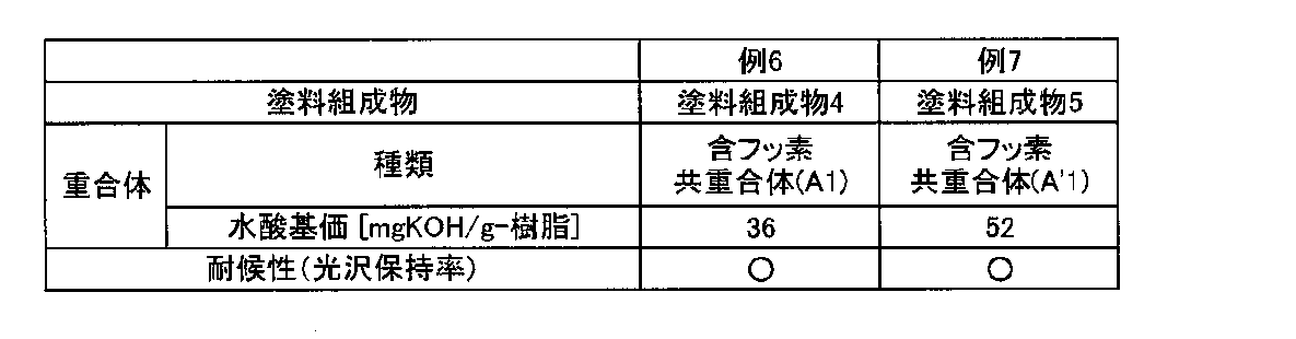
[例8]
ガラス基板の片面に、厚みが800mg/m2になるように銀メッキ処理を施し、次に、該銀メッキ膜上に、鉛を含まないエポキシ樹脂系のミラー用裏止塗料(大日本塗料社製、「SM商品名 COAT DF」)を乾燥塗膜の膜厚が、30μmとなるようにカーテンフローコーターで塗布し、180℃の乾燥炉で硬化させた。その後、徐冷炉で室温まで冷却することで、防錆塗膜付き反射鏡を得た。
次に、該防錆塗膜付き反射鏡の防錆塗膜上に、例3で得られた塗料組成物1を膜厚が30μmとなるように塗布し、180℃のオーブンで5分間乾燥硬化させることで、試験用の太陽熱集熱用反射鏡を得た。得られた太陽熱集熱用反射鏡について、実暴露試験を実施した。尚、反射鏡のエッジ部については、保護コート等の処理はしなかった。
ガラス基板の片面に、厚みが800mg/m2になるように銀メッキ処理を施し、次に、該銀メッキ膜上に、鉛を含まないエポキシ樹脂系のミラー用裏止塗料(大日本塗料社製、「SM商品名 COAT DF」)を乾燥塗膜の膜厚が、30μmとなるようにカーテンフローコーターで塗布し、180℃の乾燥炉で硬化させた。その後、徐冷炉で室温まで冷却することで、防錆塗膜付き反射鏡を得た。
次に、該防錆塗膜付き反射鏡の防錆塗膜上に、例3で得られた塗料組成物1を膜厚が30μmとなるように塗布し、180℃のオーブンで5分間乾燥硬化させることで、試験用の太陽熱集熱用反射鏡を得た。得られた太陽熱集熱用反射鏡について、実暴露試験を実施した。尚、反射鏡のエッジ部については、保護コート等の処理はしなかった。
[例9]
例4で得られた塗料組成物2を用いた以外は、例8と同様にして、太陽熱集熱用反射鏡を得た。
例4で得られた塗料組成物2を用いた以外は、例8と同様にして、太陽熱集熱用反射鏡を得た。
[耐候性試験-2]
例8および例9で得られた太陽熱集熱用反射鏡について以下の評価方法によりその性能を評価した。
[評価方法]
(実暴露試験)
沖縄県那覇市の屋外に、得られた太陽熱集熱用反射鏡の反射面(ガラス面)が表にくるように設置し(塗膜面は裏面)、設置直前と2年後を比較して、塗膜の光沢保持率、塗膜剥離の有無、銀反射層の異常について評価した。
1.塗膜の光沢保持率
塗膜表面の光沢を、PG-1M(光沢計:日本電色工業社製)を用いて測定し、以下の基準に従って耐候性を評価した。
「○」:光沢保持率が80%以上であった。
「△」:光沢保持率が60%以上80%未満であった。
「×」:光沢保持率が60%未満であった。
2.塗膜剥離の有無
以下の基準に従って耐候性を評価した。
「○」:塗膜剥離が観察されなかった。
「×」:塗膜剥離が観察された。
3.銀反射層の異常
以下の基準に従って耐候性を評価した。
「○」:銀ひけ、さび等による鏡の反射率低下が観察されなかった。
「×」:銀ひけ、さび等による鏡の反射率の低下が観察された。
例8および例9で得られた太陽熱集熱用反射鏡について以下の評価方法によりその性能を評価した。
[評価方法]
(実暴露試験)
沖縄県那覇市の屋外に、得られた太陽熱集熱用反射鏡の反射面(ガラス面)が表にくるように設置し(塗膜面は裏面)、設置直前と2年後を比較して、塗膜の光沢保持率、塗膜剥離の有無、銀反射層の異常について評価した。
1.塗膜の光沢保持率
塗膜表面の光沢を、PG-1M(光沢計:日本電色工業社製)を用いて測定し、以下の基準に従って耐候性を評価した。
「○」:光沢保持率が80%以上であった。
「△」:光沢保持率が60%以上80%未満であった。
「×」:光沢保持率が60%未満であった。
2.塗膜剥離の有無
以下の基準に従って耐候性を評価した。
「○」:塗膜剥離が観察されなかった。
「×」:塗膜剥離が観察された。
3.銀反射層の異常
以下の基準に従って耐候性を評価した。
「○」:銀ひけ、さび等による鏡の反射率低下が観察されなかった。
「×」:銀ひけ、さび等による鏡の反射率の低下が観察された。
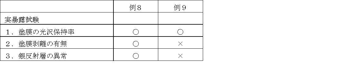
前記耐候性試験において、含フッ素共重合体(A1)を含む本発明の塗料組成物4を使用した例6の塗膜は、水酸基価が本発明の範囲外である含フッ素共重合体(A’1)を含む塗料組成物5を使用した例7の塗膜と同等の光沢保持率を有しており、充分な耐候性を有していた。
また、含フッ素共重合体(A1)を含む本発明の塗料組成物1を使用した例8の太陽熱集熱用反射鏡は、実暴露試験後の塗膜剥離は見られず、銀反射層の異常も見られなかった。一方、塗膜物性が本発明の範囲外である含フッ素共重合体(A’1)を含む塗料組成物2を使用した例9の太陽熱集熱用反射鏡は、エッジ部からの塗膜剥離が確認され、その剥離箇所の反射率が低下していた。
また、含フッ素共重合体(A1)を含む本発明の塗料組成物1を使用した例8の太陽熱集熱用反射鏡は、実暴露試験後の塗膜剥離は見られず、銀反射層の異常も見られなかった。一方、塗膜物性が本発明の範囲外である含フッ素共重合体(A’1)を含む塗料組成物2を使用した例9の太陽熱集熱用反射鏡は、エッジ部からの塗膜剥離が確認され、その剥離箇所の反射率が低下していた。
本発明の表面塗布用塗料組成物によれば、砂漠等の苛酷な条件下で使用される場合でも剥離やクラックが発生し難い、耐候性に優れた塗膜を形成できるので、太陽熱を利用する太陽熱集熱システム用等の太陽熱集熱用反射板として有用である。
なお、2010年12月14日に出願された日本特許出願2010-278576号の明細書、特許請求の範囲、図面及び要約書の全内容をここに引用し、本発明の開示として取り入れるものである。
なお、2010年12月14日に出願された日本特許出願2010-278576号の明細書、特許請求の範囲、図面及び要約書の全内容をここに引用し、本発明の開示として取り入れるものである。
1A、1B、2A、2B、3A、3B:太陽熱集熱用反射板
11:反射基板(I)
21:反射基板(II)
31:反射基板(III)
12、13、22、23、32、33:塗膜
12A、13A、22A、23A、32A、33A:塗布層
14、24、34:太陽光照射面
11:反射基板(I)
21:反射基板(II)
31:反射基板(III)
12、13、22、23、32、33:塗膜
12A、13A、22A、23A、32A、33A:塗布層
14、24、34:太陽光照射面
Claims (9)
- 下記含フッ素共重合体(A)、硬化剤(B)および溶剤(C)を含有することを特徴とする太陽熱集熱用反射板の表面塗布用塗料組成物。
含フッ素共重合体(A):フルオロオレフィンに基づく重合単位(a-1)、水酸基を有する不飽和単量体に基づく重合単位(a-2)、および炭素数6~16のアルキル基を有する不飽和単量体に基づく重合単位(a-3)を有し、水酸基価が5~47mgKOH/g-樹脂である含フッ素共重合体。 - 前記硬化剤(B)が、前記含フッ素共重合体(A)の水酸基と反応しうる官能基を1分子中に2~4個有する化合物からなる、請求項1に記載の太陽熱集熱用反射板の表面塗布用塗料組成物。
- 前記含フッ素共重合体(A)の組成が、フルオロオレフィンに基づく重合単位(a-1)が20~80モル%、水酸基を有する不飽和単量体に基づく重合単位(a-2)が1~40モル%、および炭素数6~16のアルキル基を有する不飽和単量体に基づく重合単位(a-3)が1~60モル%であり、水酸基価が5~47mgKOH/g-樹脂である、請求項1または2に記載の太陽熱集熱用反射板の表面塗布用塗料組成物。
- 前記硬化剤(B)が、-X-C(=O)-NH-(ただし、Xは水酸基を有する化合物またはアミノ基を有する化合物に由来する有機基である。)で表される構造を有し、イソシアネート基含有量が5~35質量%のイソシアネート系硬化剤である、請求項1~3のいずれか一項に記載の太陽熱集熱用反射板の表面塗布用塗料組成物。
- 反射基板の表面に、請求項1~4のいずれか一項に記載の太陽熱集熱用反射板の表面塗布用塗料組成物を塗布して塗布層を形成した後、該塗布層から溶剤(C)を除去し硬化させて塗膜を形成させることを特徴とする太陽熱集熱用反射板の製造方法。
- 前記塗料組成物として、該塗料組成物により形成された塗膜の物性が、伸び率10~200%、ガラス転移温度20~80℃、架橋密度1.0×10⁻⁴~9.0×10⁻⁴mol/cm3となる組成物を用いる請求項5に記載の太陽熱集熱用反射板の製造方法。
- 反射基板の表面に、請求項1~4のいずれか一項に記載の太陽熱集熱用反射板の表面塗布用塗料組成物を塗布して塗布層を形成し、当該塗布膜を硬化処理して得られた塗膜を有することを特徴とする太陽熱集熱用反射板。
- 前記塗膜は、伸び率10~200%、ガラス転移温度20~80℃、架橋密度1.0×10⁻⁴~9.0×10⁻⁴mol/cm3の物性を有する請求項7に記載の太陽熱集熱用反射板。
- 前記塗膜は、反射基板の太陽光照射面および当該太陽光照射面の反対側面のいずれか一方の面、または両方の面に形成されている請求項7または8に記載の太陽熱集熱用反射板。
Applications Claiming Priority (2)
| Application Number | Priority Date | Filing Date | Title |
|---|---|---|---|
| JP2010-278576 | 2010-12-14 | ||
| JP2010278576A JP2014037450A (ja) | 2010-12-14 | 2010-12-14 | 太陽熱集熱用反射板の表面塗布用塗料組成物および太陽熱集熱用反射板の製造方法 |
Publications (1)
| Publication Number | Publication Date |
|---|---|
| WO2012081642A1 true WO2012081642A1 (ja) | 2012-06-21 |
Family
ID=46244738
Family Applications (1)
| Application Number | Title | Priority Date | Filing Date |
|---|---|---|---|
| PCT/JP2011/078964 Ceased WO2012081642A1 (ja) | 2010-12-14 | 2011-12-14 | 太陽熱集熱用反射板の表面塗布用塗料組成物および太陽熱集熱用反射板の製造方法 |
Country Status (2)
| Country | Link |
|---|---|
| JP (1) | JP2014037450A (ja) |
| WO (1) | WO2012081642A1 (ja) |
Cited By (1)
| Publication number | Priority date | Publication date | Assignee | Title |
|---|---|---|---|---|
| WO2019176416A1 (ja) * | 2018-03-13 | 2019-09-19 | ナトコ株式会社 | 膜形成用樹脂組成物、積層フィルムおよび当該積層フィルムが貼り付けられた物品 |
Citations (6)
| Publication number | Priority date | Publication date | Assignee | Title |
|---|---|---|---|---|
| JPS5864452A (ja) * | 1981-10-14 | 1983-04-16 | Matsushita Electric Ind Co Ltd | 太陽熱集熱器用反射板 |
| JPS61218609A (ja) * | 1985-03-25 | 1986-09-29 | Daikin Ind Ltd | 塗装ソ−ラ−コレクタ |
| JPH05280807A (ja) * | 1992-03-31 | 1993-10-29 | Aisin Seiki Co Ltd | 太陽熱集熱装置 |
| JPH073201A (ja) * | 1993-06-18 | 1995-01-06 | Asahi Glass Co Ltd | 塗料用の硬化性樹脂組成物 |
| JPH0959559A (ja) * | 1995-08-22 | 1997-03-04 | Asahi Glass Kooto & Resin Kk | 塗料組成物 |
| JP2006152080A (ja) * | 2004-11-26 | 2006-06-15 | Nippon Paint Co Ltd | 弱溶剤型フッ素樹脂系塗料組成物および塗膜形成方法 |
-
2010
- 2010-12-14 JP JP2010278576A patent/JP2014037450A/ja active Pending
-
2011
- 2011-12-14 WO PCT/JP2011/078964 patent/WO2012081642A1/ja not_active Ceased
Patent Citations (6)
| Publication number | Priority date | Publication date | Assignee | Title |
|---|---|---|---|---|
| JPS5864452A (ja) * | 1981-10-14 | 1983-04-16 | Matsushita Electric Ind Co Ltd | 太陽熱集熱器用反射板 |
| JPS61218609A (ja) * | 1985-03-25 | 1986-09-29 | Daikin Ind Ltd | 塗装ソ−ラ−コレクタ |
| JPH05280807A (ja) * | 1992-03-31 | 1993-10-29 | Aisin Seiki Co Ltd | 太陽熱集熱装置 |
| JPH073201A (ja) * | 1993-06-18 | 1995-01-06 | Asahi Glass Co Ltd | 塗料用の硬化性樹脂組成物 |
| JPH0959559A (ja) * | 1995-08-22 | 1997-03-04 | Asahi Glass Kooto & Resin Kk | 塗料組成物 |
| JP2006152080A (ja) * | 2004-11-26 | 2006-06-15 | Nippon Paint Co Ltd | 弱溶剤型フッ素樹脂系塗料組成物および塗膜形成方法 |
Cited By (2)
| Publication number | Priority date | Publication date | Assignee | Title |
|---|---|---|---|---|
| WO2019176416A1 (ja) * | 2018-03-13 | 2019-09-19 | ナトコ株式会社 | 膜形成用樹脂組成物、積層フィルムおよび当該積層フィルムが貼り付けられた物品 |
| US11118087B2 (en) | 2018-03-13 | 2021-09-14 | Natoco Co., Ltd. | Film-forming resin composition, laminated film, and article to which laminated film is attached |
Also Published As
| Publication number | Publication date |
|---|---|
| JP2014037450A (ja) | 2014-02-27 |
Similar Documents
| Publication | Publication Date | Title |
|---|---|---|
| JPWO2012046783A1 (ja) | 太陽熱集熱用反射板の表面塗布用塗料組成物および太陽熱集熱用反射板の製造方法 | |
| CN102770498B (zh) | 太阳能集热用反射镜用的涂料组合物、以及太阳能集热用反射镜及其制造方法 | |
| JP5494325B2 (ja) | 風力発電機のブレードの表面塗布用塗料組成物および風力発電機のブレードの製造方法 | |
| EP3219769A1 (en) | Powder coating composition, powder coating and painted article | |
| JPWO2011108497A1 (ja) | 太陽熱集熱用反射板用の塗料組成物、ならびに太陽熱集熱用反射板およびその製造方法 | |
| JP2004307666A (ja) | 塗料用含フッ素共重合体、塗料用組成物および塗料 | |
| WO2020017563A1 (ja) | 塗料、塗膜付き基材、及び塗膜付き基材の製造方法 | |
| JP2014037450A (ja) | 太陽熱集熱用反射板の表面塗布用塗料組成物および太陽熱集熱用反射板の製造方法 | |
| WO2012141155A1 (ja) | 太陽熱集熱用反射鏡およびその製造方法 | |
| JP5464258B2 (ja) | 塗料、塗膜、太陽電池モジュールのバックシート、及び、太陽電池モジュール | |
| WO2012147569A1 (ja) | 塗装物品および鏡の製造方法 | |
| JP6863469B2 (ja) | 防錆塗料、塗膜及び積層体 | |
| JP2012167226A (ja) | 太陽熱集熱用反射板の表面塗布用塗料組成物および太陽熱集熱用反射板の製造方法 | |
| CN108368373A (zh) | 涂料组合物及涂装体 | |
| JP2013116427A (ja) | 塗装物品および鏡の製造方法 | |
| JP2025165116A (ja) | 含フッ素塗料用組成物、及び、塗装物品 | |
| WO2006073058A1 (ja) | 硬化型含フッ素塗料用組成物 | |
| JP2015025026A (ja) | 塗料用組成物 | |
| JP7685377B2 (ja) | 積層体及び積層体の製造方法 | |
| CN116063914A (zh) | 涂料组合物、涂膜及涂装体 | |
| US20240360333A1 (en) | Aqueous dispersion, coating composition, coating film and coated article | |
| JP2013023604A (ja) | 太陽熱集熱用反射板の表面塗布用塗料組成物および太陽熱集熱用反射板の製造方法 | |
| JP2022173740A (ja) | 塗料及び塗膜付き基材 | |
| JP2015067783A (ja) | 含フッ素重合体溶液の製造方法、および含フッ素塗料組成物の製造方法 | |
| JPH0490872A (ja) | 上塗り塗装方法 |
Legal Events
| Date | Code | Title | Description |
|---|---|---|---|
| 121 | Ep: the epo has been informed by wipo that ep was designated in this application |
Ref document number: 11849236 Country of ref document: EP Kind code of ref document: A1 |
|
| NENP | Non-entry into the national phase |
Ref country code: DE |
|
| 122 | Ep: pct application non-entry in european phase |
Ref document number: 11849236 Country of ref document: EP Kind code of ref document: A1 |
|
| NENP | Non-entry into the national phase |
Ref country code: JP |