WO2012081576A1 - 水素分離装置 - Google Patents
水素分離装置 Download PDFInfo
- Publication number
- WO2012081576A1 WO2012081576A1 PCT/JP2011/078789 JP2011078789W WO2012081576A1 WO 2012081576 A1 WO2012081576 A1 WO 2012081576A1 JP 2011078789 W JP2011078789 W JP 2011078789W WO 2012081576 A1 WO2012081576 A1 WO 2012081576A1
- Authority
- WO
- WIPO (PCT)
- Prior art keywords
- hydrogen
- layer
- gas
- mixed gas
- flow path
- Prior art date
- Legal status (The legal status is an assumption and is not a legal conclusion. Google has not performed a legal analysis and makes no representation as to the accuracy of the status listed.)
- Ceased
Links
Images
















Classifications
-
- B—PERFORMING OPERATIONS; TRANSPORTING
- B01—PHYSICAL OR CHEMICAL PROCESSES OR APPARATUS IN GENERAL
- B01D—SEPARATION
- B01D53/00—Separation of gases or vapours; Recovering vapours of volatile solvents from gases; Chemical or biological purification of waste gases, e.g. engine exhaust gases, smoke, fumes, flue gases, aerosols
- B01D53/22—Separation of gases or vapours; Recovering vapours of volatile solvents from gases; Chemical or biological purification of waste gases, e.g. engine exhaust gases, smoke, fumes, flue gases, aerosols by diffusion
-
- B—PERFORMING OPERATIONS; TRANSPORTING
- B01—PHYSICAL OR CHEMICAL PROCESSES OR APPARATUS IN GENERAL
- B01D—SEPARATION
- B01D63/00—Apparatus in general for separation processes using semi-permeable membranes
- B01D63/08—Flat membrane modules
- B01D63/082—Flat membrane modules comprising a stack of flat membranes
-
- C—CHEMISTRY; METALLURGY
- C01—INORGANIC CHEMISTRY
- C01B—NON-METALLIC ELEMENTS; COMPOUNDS THEREOF; METALLOIDS OR COMPOUNDS THEREOF NOT COVERED BY SUBCLASS C01C
- C01B3/00—Hydrogen; Gaseous mixtures containing hydrogen; Separation of hydrogen from mixtures containing it; Purification of hydrogen; Reversible storage of hydrogen
- C01B3/50—Separation of hydrogen or hydrogen-containing gases from gaseous mixtures, e.g. purification
- C01B3/501—Separation of hydrogen or hydrogen-containing gases from gaseous mixtures, e.g. purification by diffusion
- C01B3/503—Separation of hydrogen or hydrogen-containing gases from gaseous mixtures, e.g. purification by diffusion characterised by membranes
-
- C—CHEMISTRY; METALLURGY
- C01—INORGANIC CHEMISTRY
- C01B—NON-METALLIC ELEMENTS; COMPOUNDS THEREOF; METALLOIDS OR COMPOUNDS THEREOF NOT COVERED BY SUBCLASS C01C
- C01B3/00—Hydrogen; Gaseous mixtures containing hydrogen; Separation of hydrogen from mixtures containing it; Purification of hydrogen; Reversible storage of hydrogen
- C01B3/50—Separation of hydrogen or hydrogen-containing gases from gaseous mixtures, e.g. purification
- C01B3/501—Separation of hydrogen or hydrogen-containing gases from gaseous mixtures, e.g. purification by diffusion
- C01B3/503—Separation of hydrogen or hydrogen-containing gases from gaseous mixtures, e.g. purification by diffusion characterised by membranes
- C01B3/505—Membranes containing palladium
-
- B—PERFORMING OPERATIONS; TRANSPORTING
- B01—PHYSICAL OR CHEMICAL PROCESSES OR APPARATUS IN GENERAL
- B01D—SEPARATION
- B01D2256/00—Main component in the product gas stream after treatment
- B01D2256/16—Hydrogen
-
- C—CHEMISTRY; METALLURGY
- C01—INORGANIC CHEMISTRY
- C01B—NON-METALLIC ELEMENTS; COMPOUNDS THEREOF; METALLOIDS OR COMPOUNDS THEREOF NOT COVERED BY SUBCLASS C01C
- C01B2203/00—Integrated processes for the production of hydrogen or synthesis gas
- C01B2203/04—Integrated processes for the production of hydrogen or synthesis gas containing a purification step for the hydrogen or the synthesis gas
- C01B2203/0405—Purification by membrane separation
-
- C—CHEMISTRY; METALLURGY
- C01—INORGANIC CHEMISTRY
- C01B—NON-METALLIC ELEMENTS; COMPOUNDS THEREOF; METALLOIDS OR COMPOUNDS THEREOF NOT COVERED BY SUBCLASS C01C
- C01B2203/00—Integrated processes for the production of hydrogen or synthesis gas
- C01B2203/04—Integrated processes for the production of hydrogen or synthesis gas containing a purification step for the hydrogen or the synthesis gas
- C01B2203/0465—Composition of the impurity
- C01B2203/047—Composition of the impurity the impurity being carbon monoxide
-
- C—CHEMISTRY; METALLURGY
- C01—INORGANIC CHEMISTRY
- C01B—NON-METALLIC ELEMENTS; COMPOUNDS THEREOF; METALLOIDS OR COMPOUNDS THEREOF NOT COVERED BY SUBCLASS C01C
- C01B2203/00—Integrated processes for the production of hydrogen or synthesis gas
- C01B2203/04—Integrated processes for the production of hydrogen or synthesis gas containing a purification step for the hydrogen or the synthesis gas
- C01B2203/0465—Composition of the impurity
- C01B2203/0475—Composition of the impurity the impurity being carbon dioxide
-
- H—ELECTRICITY
- H01—ELECTRIC ELEMENTS
- H01M—PROCESSES OR MEANS, e.g. BATTERIES, FOR THE DIRECT CONVERSION OF CHEMICAL ENERGY INTO ELECTRICAL ENERGY
- H01M8/00—Fuel cells; Manufacture thereof
- H01M8/06—Combination of fuel cells with means for production of reactants or for treatment of residues
- H01M8/0662—Treatment of gaseous reactants or gaseous residues, e.g. cleaning
- H01M8/0687—Reactant purification by the use of membranes or filters
-
- Y—GENERAL TAGGING OF NEW TECHNOLOGICAL DEVELOPMENTS; GENERAL TAGGING OF CROSS-SECTIONAL TECHNOLOGIES SPANNING OVER SEVERAL SECTIONS OF THE IPC; TECHNICAL SUBJECTS COVERED BY FORMER USPC CROSS-REFERENCE ART COLLECTIONS [XRACs] AND DIGESTS
- Y02—TECHNOLOGIES OR APPLICATIONS FOR MITIGATION OR ADAPTATION AGAINST CLIMATE CHANGE
- Y02E—REDUCTION OF GREENHOUSE GAS [GHG] EMISSIONS, RELATED TO ENERGY GENERATION, TRANSMISSION OR DISTRIBUTION
- Y02E60/00—Enabling technologies; Technologies with a potential or indirect contribution to GHG emissions mitigation
- Y02E60/30—Hydrogen technology
- Y02E60/50—Fuel cells
Definitions
- the present invention relates to a hydrogen separator for separating hydrogen from a hydrogen-containing gas using a hydrogen permeable membrane such as a metal membrane that selectively permeates hydrogen.
- Patent Document 1 discloses a configuration including a leak prevention mechanism between a gas inlet of a mixed gas layer and an inlet of a permeate gas layer. However, nothing is said about the seal between the hydrogen separation layer, the mixed gas layer and the permeate gas layer.
- the seal between the layers constituting the laminate needs to be realized in close contact with each other, and a technique of sealing with a wire like a knife edge cannot be used.
- Each layer constituting the laminate is thin and difficult to join and seal by welding.
- the state-of-the-art hydrogen permeable membrane used for the hydrogen separation layer is mechanically and heat resistant and often has to be bonded and sealed under mild conditions.
- the laminate must be assembled so that the hydrogen separation layer does not impair its hydrogen separation ability, and a sufficient seal must be realized. If the seal between the layers is incomplete, not only will the components of the mixed gas layer enter the permeate gas layer and the quality of the hydrogen in the permeate gas will deteriorate, but in some cases, the atmosphere outside the laminate will enter the permeate gas. Even there.
- An object of the present invention is to solve the above-described problems of the prior art, and to provide a stacked hydrogen separator capable of assembling a stacked body under mild conditions and realizing an excellent seal.
- the hydrogen separation device of the present invention includes a hydrogen separation layer that selectively permeates hydrogen, a mixed gas layer having a mixed gas flow path adjacent to the hydrogen separation layer and through which a hydrogen-containing gas flows, and a hydrogen separation layer adjacent to the hydrogen separation layer. It is composed of a laminate obtained by laminating and integrating a permeate gas layer having a permeate gas flow path through which hydrogen permeated through the layer and a container filled with the buffer gas and containing the laminate.
- a buffer space through which the buffer gas can reach at least one end surface in the stacking direction of the stack is provided between the stack and the inner wall of the container, and the pressure of the buffer space is adjusted between the mixed gas flow path and the permeate gas flow.
- the hydrogen separator is set to be equal to or higher than the higher pressure in the channel. In other words, the layered body should not have a part with higher pressure than the buffer space.
- Hydrogen separation layers include hydrogen-permeable metal membranes, composite membranes with thin hydrogen-permeable metals formed on porous ceramics, porous ceramic membranes with molecular-scale pores, and dense and selective hydrogen.
- a perovskite ceramic film or the like to be permeated can be used.
- various films such as a Pd film, a Pd—Ag alloy film, a Pd—Cu alloy film, a V—Ni alloy film, an amorphous Zr—Ni alloy film can be used. Further, in recent years, a technique for thinning mainly aimed at improving the hydrogen permeation rate has advanced remarkably, and a foil-like film having a thickness of less than 20 ⁇ m has been developed. In the present invention, such a foil-like film can also be used.
- the hydrogen separation layer is composed of three parts. That is, it is not in close contact with the constituent members of the mixed gas layer or the permeate gas layer, but is in close contact with the constituent members of the mixed gas layer or the permeate gas layer adjacent to the hydrogen permeable portion through which hydrogen can permeate. It is a through-hole which comprises the interlayer communication hole provided in the area
- the hydrogen separation layer does not necessarily need to have hydrogen permeability over the entire surface, and in particular, does not require hydrogen permeability in the seal portion.
- the configuration and composition may be inclined so that the hydrogen permeability is lowered in the vicinity of the seal part.
- the hydrogen permeable portion may be made of Pd, and a Ni component may be added as it approaches the seal portion so that the seal portion becomes Ni.
- the mixed gas layer and permeate gas layer are each composed of three parts, like the hydrogen separation layer. That is, it is not in close contact with adjacent components such as a hydrogen separation layer, and corresponds to a hydrogen permeation portion of the hydrogen separation layer, a hydrogen permeation portion corresponding region through which a gas such as hydrogen flows, and a gas flow path exposed on the surface.
- This is a through-hole that surrounds the entire circumference and is provided in the region of the seal portion and the seal portion that are in close contact with adjacent components such as a hydrogen separation layer, and constitutes an interlayer communication hole.
- an intra-layer communication channel that connects the hydrogen permeation portion corresponding region and the through hole is provided in the seal portion.
- the mixed gas flow path in the present invention refers to a space in which the mixed gas can flow in the hydrogen permeation portion corresponding region and an in-layer communication flow path communicating with the space.
- the permeate gas flow path refers to a space in which hydrogen gas that has permeated the hydrogen separation layer in the hydrogen permeation portion corresponding region can flow and an intra-layer communication flow path that communicates therewith. That is, hydrogen may not flow in the intralayer communication channel upstream of the hydrogen permeation portion corresponding region, but this intralayer communication channel is also included in the permeate gas channel.
- the mixed gas layer and the permeate gas layer may be configured such that the mixed gas flow path or the permeate gas flow path of the hydrogen permeation portion corresponding region is exposed only on one side and the hydrogen separation layer is provided only on the one side. It is desirable to expose the mixed gas flow path or the permeate gas flow path in the hydrogen permeation portion corresponding region and to provide the hydrogen separation layer on both sides because the stack can be made compact when many hydrogen separation layers are provided.
- the hydrogen separation layer is provided on both sides of the mixed gas layer and the permeate gas layer, the mixed gas layer and the permeate gas layer are alternately provided in the stacking direction via the hydrogen separation layer between them,
- An end plate that seals and seals the end face is provided on the end face of the mixed gas layer or the permeate gas layer that is the end in the stacking direction.
- the end plate has a seal portion in close contact with the hydrogen permeation portion corresponding region and the adjacent mixed gas layer or the constituent member of the permeate gas layer.
- the hydrogen permeation part corresponding region in the end plate is only for sealing the mixed gas channel or permeate gas channel of the adjacent mixed gas layer or the hydrogen permeation part corresponding region of the permeate gas layer, and a special configuration is necessary. And not.
- the end plate on the side where the pipe is attached is provided with a gas flow path such as a through hole that communicates the pipe with the interlayer communication hole.
- the laminated body only needs to be integrated and does not require strong bonding.
- the number of bolts can be reduced and the bolts can be made thinner.
- the hydrogen separator can be made compact.
- the heat treatment temperature for bonding can be lowered and bonding can be performed in a short time.
- the pressure at the time of joining can also be made low. According to the present invention, it is possible to assemble a hydrogen separator using a hydrogen permeable membrane made of a thin foil-like membrane that is weak and easily deformed at a high temperature or a brittle ceramic as a hydrogen separation layer.
- the hydrogen separator is required to have airtightness inside and outside the apparatus, but in the present invention, airtightness can be easily secured by using a robust container.
- a conventional hydrogen separator composed of a laminate it is difficult to ensure airtightness inside and outside the laminate. Sealing between layers needs to be realized in close contact with each other, and a technique of sealing with a line like a knife edge cannot be used. Moreover, since it operates at several hundred degrees Celsius, a polymer gasket cannot be used.
- welding as an airtight and reliable sealing technique is applied to a laminate of thin layered members, there is a concern that the complicated structure and the performance of the hydrogen separation layer may be impaired.
- the container is separated from the laminate, and the container can be sealed using welding, and high airtightness can be easily realized. As a result, even when the laminate collapses during use, it is safe because hydrogen does not leak out of the hydrogen separator.
- the buffer gas filling the container it is preferable to introduce hydrogen, water vapor or inert gas.
- hydrogen When hydrogen is introduced, even if there is a leak due to poor bonding in the laminated body, only the hydrogen surrounding the laminated body flows in, so the purity of the permeate gas does not decrease.
- Hydrogen introduced as a buffer gas is not necessarily high-purity hydrogen. If the amount of high-purity hydrogen that permeates the hydrogen separation layer is sufficiently large compared to hydrogen mixed in due to leakage, impurities in hydrogen mixed in due to leakage become negligible.
- water vapor When water vapor is allowed to flow into the permeate gas flow path and the permeated hydrogen is swept, water vapor can be used as the buffer gas. Even if there is a leak in the laminate due to poor bonding, the quality of the permeate gas is not deteriorated because only the water vapor flows in.
- the water vapor may be introduced from outside the hydrogen separator, but the function can also be realized by filling the container with water.
- the hydrogen separator is generally operated at a temperature of 300 to 500 ° C. At that temperature, the water enclosed in the container becomes water vapor, which may be higher than the pressure of the mixed gas passage and the permeate gas passage. it can. In this way, it is not necessary to prepare water vapor specially.
- an inert gas may be contained in hydrogen obtained using a hydrogen separator
- an inert gas can be used as a buffer gas. Even if there is a leak due to poor bonding in the laminated body, only an inert gas is mixed in, and this does not cause a functional problem.
- the configuration of the apparatus can be simplified by using a hydrogen separation apparatus in which the higher pressure of the mixed gas flow path and the permeate gas flow path is in communication with the buffer space. That is, the gas itself flowing through the mixed gas passage or the permeate gas passage can be used as the buffer gas, and there is no need to introduce a new gas.
- the mixed gas flow is particularly increased by setting the pressure of the permeate gas flow path higher than the mixed gas flow path In such a case, by connecting the permeate gas flow path with the buffer space, a portion having a higher pressure than the buffer space is formed in the laminated body. I can not.
- the pressures of the permeate gas flow path and the buffer space are strictly different due to pressure loss such as interlayer communication holes.
- pressure loss such as interlayer communication holes.
- the permeate gas flow path and the buffer space are in communication, their pressures are considered equal.
- the mixed gas flow path and the buffer space communicate with each other, their pressures are considered to be equal.
- a hydrogen separation device in which the mixed gas flow path communicates with the buffer space.
- the pressure of the mixed gas channel is higher than that of the permeate gas channel during operation.
- the mixed gas flow path and the buffer space there can be no portion having a higher pressure than the buffer space in the laminated body. Even if the laminate collapses during operation, a gas having a lower purity than the supplied hydrogen-containing gas is not discharged as a permeate gas, and can be used with confidence.
- the structure of the hydrogen separating apparatus can be further simplified by using a hydrogen separation apparatus in which the hydrogen-containing gas flows through the buffer space to the mixed gas flow path.
- a hydrogen separation apparatus in which the hydrogen-containing gas flows through the buffer space to the mixed gas flow path.
- Such a structure can be obtained, for example, by attaching a pipe for introducing a hydrogen-containing gas into the buffer space to the container and opening the inter-layer communication channel of the mixed gas channel of the laminate to the buffer space.
- the inter-layer communication channel of the mixed gas channel opened to the buffer space does not have to be one for each layer, and a plurality of layers can be provided as necessary. Or it is good also as a structure which opens the interlayer communication hole connected to the communication flow path in a layer to buffer space.
- a pipe connecting the flow path in the laminated body and the outside of the container can be used as two hydrogen separators.
- the number of pipes that connect the permeate gas flow path and the outside of the container can be one. If the hydrogen separation device in which the hydrogen-containing gas flows into the mixed gas flow path through the buffer space, one pipe for taking out the gas that did not permeate the hydrogen separation layer was provided, and the two pipes were connected to the laminate.
- a hydrogen separator can be constructed.
- a configuration may be adopted in which a hydrogen-containing gas is introduced into the mixed gas flow path through a pipe, and the gas that has not permeated the hydrogen separation layer is taken out of the container through the buffer space. Again, there are only two pipes connected to the laminate, and the same effect can be obtained.
- the assembly of the laminate can be facilitated by using a hydrogen separator in which the pipe connecting the flow path in the laminate and the outside of the container is connected to the layer inside the end face of the laminate. That is, since there is no complicated configuration such as piping on the two end faces in the stacking direction of the stacked body, it can be easily tightened from both ends, and diffusion bonding and brazing are facilitated.
- the gas flow path that connects the pipe and the interlayer communication hole is provided in the mixed gas layer or the permeate gas layer.
- a relatively thick pipe connection plate having a pipe connection portion on the peripheral surface is provided as a layer of the laminate, and a gas flow path that connects the pipe and the interlayer communication hole is formed on the plate. You may do it.
- the hydrogen separation apparatus has a portion with a width of 1 mm or less in the in-layer direction in the in-layer communication channel.
- the in-layer communication channel is used to introduce the mixed gas into the hydrogen permeable part corresponding region of the mixed gas channel, and the remaining gas that has not permeated through the hydrogen permeable part corresponding region of the mixed gas channel is discharged.
- the permeation amount of the hydrogen separator can be increased in proportion to the number of layers because the layers function effectively.
- each of the mixed gas layer and the permeate gas layer is composed of a plurality of plate-like members, at least one of which has the intra-layer communication channel, and the hydrogen of the plate-like member. It is preferable to use a plate-like member in which the flow path is divided so as not to communicate the transmission portion corresponding region in plan view.
- one of the plate-like members includes a member having the intra-layer communication flow path.
- the flow path of the hydrogen permeation portion corresponding region is divided so as not to communicate in a planar manner. If another plate-like member is formed so as to connect the divided flow paths, the gas introduced from the in-layer communication flow path flows uniformly in a three-dimensional manner, and hydrogen can be separated efficiently. It becomes possible. Moreover, the structure of each plate-like member is simplified, and the manufacturing cost can be suppressed.
- the flow path is divided so that the seal member which is in close contact with the seal portion of the hydrogen separation layer and the seal portion of another plate-like member and enhances the airtightness and the bonding strength is also not communicated in a planar manner. You may make it the structure which is.
- the seal member is often made of a thin and soft material, and the seal member consisting only of the seal portion is easily deformed and difficult to handle.
- the structure is stable and can be easily handled by dividing the flow path so that the sealing member does not communicate in a planar manner and bridging at the divided portion. If the other plate-like members are formed so as to connect the divided flow paths, the effective membrane area will not be impaired, but rather the gas will flow uniformly in the hydrogen permeation area corresponding region, thus improving the hydrogen separation efficiency. To do.
- the hydrogen permeation part corresponding region by using a hydrogen separation device in which the members constituting the adjacent hydrogen separation layer and the mixed gas layer and permeate gas layer are not in close contact with each other, the entire surface of the hydrogen permeation part is utilized for hydrogen permeation. At the same time, the structure can withstand the pressure difference.
- a foil-like metal membrane is used for the hydrogen separation layer, a method is disclosed in which a support member and a foil-like metal membrane are intimately integrated to supplement the mechanical strength.
- the portion in close contact with the support member does not allow hydrogen to permeate, reducing the effective membrane area available for permeation.
- the hydrogen separation layer tends to break during assembly when it is in close contact with the support member, and rather it is supported by the divided parts of the plate-like member without close contact. I found it effective. Based on the result, the present invention has been reached in which the members in the hydrogen permeation portion corresponding region are closely related.
- the present invention has the above-described features, and is summarized as follows.
- a hydrogen separation layer that selectively permeates hydrogen, a mixed gas layer adjacent to one surface of the hydrogen separation layer, a mixed gas passage through which a hydrogen-containing gas flows, and a mixed gas passage exposed on the surface
- a permeate gas layer adjacent to the other surface of the hydrogen separation layer, in which hydrogen that has permeated the hydrogen separation layer flows.
- a laminated body obtained by laminating and integrating a permeate gas layer having a gas flow path and a perimeter of the permeate gas flow path exposed on the surface and having a seal portion in close contact with the hydrogen separation layer;
- a container filled with a buffer gas, and a buffer space through which the buffer gas can reach is provided between at least one end face in the stacking direction of the stack, between the stack and the inner wall of the container;
- Pressure is mixed gas flow A higher pressure equal to or higher than the hydrogen separation device of the permeate gas flow path.
- the hydrogen separator according to (1) wherein the hydrogen-containing gas flows into the mixed gas flow path through the buffer space.
- the laminate includes a pipe connection plate having a larger layer thickness than the mixed gas layer and the permeate gas layer, and a pipe connecting the flow path in the laminate and the outside of the container is connected to a surface around the pipe connection plate.
- a hydrogen separator using a laminate having excellent durability can be obtained.
- the laminated body can be assembled and integrated without applying high temperature or a large force to the hydrogen separation layer, it is possible to use a thin membrane or a fragile hydrogen separation layer that has higher performance than before.
- strong bonding is not required, and the apparatus can be miniaturized. The configuration becomes simple, and the production yield and cost can be suppressed. And even if a laminated body collapses, air
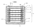
- FIG. 3 is a cross-sectional view taken along the line AB of FIG.
- FIG. 3 is a cross-sectional view taken along the line CD of FIG.
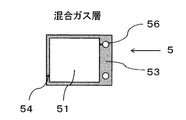
- FIG. 3 is a top view which shows the mixed gas layer of 1st Example.
- FIG. 3 shows the permeation
- FIG. 10 is a cross-sectional view taken along the line AB in FIG. 9.
- FIG. 10 is a cross-sectional view taken along the line CD of FIG. It is a perspective view which shows 3rd Embodiment of a hydrogen separator (The laminated body and piping in a container are permeate
- FIG. 14 is a cross-sectional view taken along the line AB in FIG. 13.
- FIG. 14 is a sectional view taken along line CD in FIG. 13.
- FIG. 21 is a cross-sectional view taken along the line AB of FIG. It is a perspective view which shows 5th Embodiment of a hydrogen separator (The laminated body and piping in a container are permeate
- FIG. 24 is a cross-sectional view taken along the line AB of FIG.
- FIG. 24 is a cross-sectional view taken along the line CD of FIG.
- FIG. 3 It is a top view which shows the structural member (plate-shaped member) of a mixed gas layer. It is a top view which shows another example of the structural member (plate-shaped member) of a mixed gas layer. It is a top view which shows the structural member (plate-shaped member) of the mixed gas layer used for the Example. It is a top view which shows the structural member (plate-shaped member) of the mixed gas layer of another Example. It is a perspective view which shows the hydrogen separation apparatus of Example 3 (The laminated body and piping in a container are permeate
- FIG. 32 is a cross-sectional view taken along the line AB of FIG. 31.
- FIG. 32 is a sectional view taken along line CD of FIG. 31.
- Gas chroma of gas obtained from mixed gas discharge pipe (dotted line) and permeated gas discharge pipe (solid line) when mixed gas is introduced into mixed gas flow path after increasing / decreasing pressure of mixed gas flow path at 800 kPa / min It is a graph which shows a graph measurement result. It is a graph which shows the relationship between an operation time and the hydrogen flow rate obtained from permeate gas discharge piping.
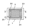
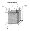
- FIG. 1 shows a first embodiment of the hydrogen separator according to the present invention.
- This 1st Embodiment is comprised from the laminated body 3 and the container 1 which includes it.
- a mixed gas introduction pipe 21 that guides the mixed gas from the outside of the container 1 to the laminate 3
- a mixed gas discharge pipe 23 that guides the remaining gas that has not permeated the hydrogen separation layer 4 from the laminate 3 to the outside of the container 1, and a permeate gas flow path
- a sweep gas introduction pipe 22 for introducing a sweep gas from the outside of the container 1 into the laminate 3
- a permeate gas discharge pipe 24 for guiding the permeate gas from the inside of the laminate 3 to the outside of the container 1, and the laminate 3
- a buffer gas introduction pipe 25 for introducing a buffer gas into the buffer space 11 between the inner wall of the container 1.
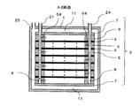
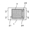
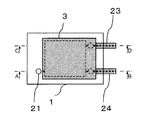
- FIG. 2 is a top view of the above hydrogen separator, and a cross section AB is shown in FIG.
- the laminate 3 is a laminate of a hydrogen separation layer 4, a mixed gas layer 5, and a permeate gas layer 6, and appropriate joining means such as diffusion joining together with end plates 7 at both ends in the lamination direction. It is integrated with.
- the mixed gas is introduced from the outside of the container 1 into the laminate 3 and distributed to the four mixed gas layers 5 in the drawing through the interlayer communication holes 8. While flowing through the hydrogen permeable portion corresponding region of the mixed gas flow path, hydrogen passes through the hydrogen separation layer 4 and flows into the hydrogen permeable portion corresponding region of the permeated gas flow path. This gas is collected through the intralayer communication channel 64 and the interlayer communication hole 8 of the permeate gas channel, and is taken out of the container 1 through the pipe 24. In this way, hydrogen can be separated from the mixed gas.
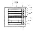
- FIG. 4 shows a cross section along line CD in FIG.
- the gas that has not permeated the hydrogen separation layer 4 is collected through the in-layer communication channel 54 and the interlayer communication hole 8 of the mixed gas channel in this cross section, and is discharged out of the container 1 through the pipe 23.
- the sweep gas is introduced into the hydrogen permeation portion corresponding region of the permeate gas flow path through the interlayer communication hole 8 of this cross section and the intralayer communication flow path 64 of the permeate gas flow path.
- the same gas as the sweep gas is introduced into the buffer space 11.
- this pressure the same as or higher than the higher pressure of the mixed gas flow path in the mixed gas layer 5 and the permeate gas flow path in the permeate gas layer 6,
- the force to spread and collapse is no longer applied.
- excellent durability can be obtained.
- the buffer gas and the sweep gas are the same gas, even if the sealing on both sides of the permeate gas layer 6 is insufficient, or even if the laminate 3 collapses during use, the mixed gas introduced And nothing other than buffer gas components.
- the container 1 can be hermetically sealed by welding to increase the airtight reliability. In a hydrogen separator that does not use a container, when the laminate collapses, not only atmospheric components are mixed into the permeated gas, but also a mixed gas containing hydrogen leaks into the atmosphere, which is dangerous.
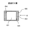
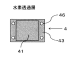
- the mixed gas layer 5, the permeate gas layer 6, and the hydrogen separation layer 4 all have through-holes 56, 66 at the four corners in the area of the seal portions 53, 63, 43 and the seal portions 53, 63, 43 around the entire periphery. , 46.
- These through holes 56, 66, and 46 constitute interlayer communication holes that communicate in the stacking direction when stacked.
- the hydrogen separation layer 4 has a hydrogen permeable part 41 at the center.
- the mixed gas layer 5 and the permeate gas layer 6 have an opening at the center, and this portion becomes a hydrogen permeation portion corresponding region 51 of the mixed gas flow channel and a hydrogen permeation portion corresponding region 61 of the permeate gas flow channel. These are regions corresponding to hydrogen permeable portions, and hydrogen permeates through the adjacent hydrogen separation layers 4.
- the sealing portions 53 and 63 of the mixed gas layer 5 and the permeating gas layer 6 are flat for sealing, and the intra-layer communication channels 54 and 64 that are not exposed on the surface of the sealing portion are provided inside the sealing portions 53 and 63. Is provided. Gas is introduced into the hydrogen permeation portion corresponding regions 51, 61 from the through holes 56 (or 66, 46) for the interlayer communication holes 8 through the intra-layer communication channels 54, 64, or from the hydrogen permeation portion corresponding regions 51, 61. Gas can be taken out to the through hole 56 (or 66, 46) for the interlayer communication hole 8.
- the width of the in-layer communication channel is 1 mm or less, preferably 0.6 mm or less. There may be a wider part, but it is preferable to provide at least one such part. When the width is wide, a sufficient pressure cannot be applied when the laminate is integrated at the seal portion of the permeate gas layer corresponding to the stacking direction of the in-layer communication channel 54 of the mixed gas layer, and leakage occurs. There is.
- the mixed gas flows from the through hole (interlayer communication hole) 66 through which the mixed gas flows in the permeate gas layer into the hydrogen permeation portion corresponding region 61 of the permeate gas layer, and the quality of the permeate gas is deteriorated.
- sufficient pressure cannot be applied when the laminate is integrated at the seal portion of the mixed gas layer corresponding to the lamination direction of the in-layer communication channel 64 of the permeate gas layer, resulting in leakage. That is, the mixed gas flows from the hydrogen permeable portion corresponding region 51 of the mixed gas layer into the through hole (interlayer communication hole) 56 through which the permeable gas flows in the mixed gas layer, and the quality of the permeable gas is deteriorated.
- the shapes of the mixed gas layer 5 and the permeate gas layer 6 do not generally need to be the same, but can be the same configuration when turned over as in this embodiment. By doing so, the types of members can be reduced, and it can be manufactured at low cost.
- FIG. 8 shows a second embodiment of the hydrogen separator according to the present invention.
- the pipe 21 for introducing the mixed gas communicates with the buffer space 11 in the container, and the interlayer communication hole 8 for introducing the mixed gas of the laminate 3 is opened in the container.
- the configuration is the same as that of the first embodiment except that the pipe provided for introducing gas between the laminate 3 and the inner wall of the container 1 is removed. This embodiment is applied when the pressure of the mixed gas channel 51 (or 54) is equal to or higher than the pressure of the permeate gas channel 61 (or 64).
- FIG. 9 is a top view of the hydrogen separator, and a cross section AB is shown in FIG.
- the mixed gas introduced into the container from the mixed gas introduction pipe 21 fills the buffer space 11.
- This mixed gas is introduced into the mixed gas flow path 51 (and 54) in the laminate 3. That is, the pressure in the buffer space 11 is the same as that of the mixed gas channel 51 (or 54).
- the buffer gas is a mixed gas to be supplied, even if the sealing on both sides of the permeate gas layer 6 is insufficient, or even if the laminate 3 collapses during use, the components of the introduced mixed gas Do not mix except.
- the container 1 can be hermetically sealed by sealing it to improve hermetic reliability.
- a hydrogen separator that does not use a container, when the laminate collapses, not only atmospheric components are mixed into the permeated gas, but also a mixed gas containing hydrogen leaks into the atmosphere, which is dangerous.
- FIG. 11 is a cross-sectional view taken along the line CD in FIG. Since the configuration of the mixed gas layer 5, the permeate gas layer 6, and the hydrogen separation layer 4 to be used is the same as that of the first embodiment, the drawing is omitted.
- FIG. 12 shows a third embodiment of the hydrogen separator according to the present invention.
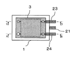
- the third embodiment there is no pipe for introducing the sweep gas. Therefore, as shown in the top view of FIG. 13, the second pipe except for some pipes at the left end of the laminate 3, interlayer communication holes, and the like is eliminated. This is the same as the embodiment.
- no sweep gas is used, and high-purity hydrogen is obtained from the permeate gas discharge pipe 24. Since a hydrogen partial pressure difference is necessary for hydrogen permeation, the pressure of the introduced mixed gas is higher than that of the permeated gas.
- FIG. 14 shows a cross section AB of FIG.
- the mixed gas introduced into the container 1 from the mixed gas introduction pipe 21 fills the buffer space 11.
- This mixed gas is introduced into the hydrogen permeable part corresponding region 51 of the mixed gas flow path in the stacked body 3 through the intra-layer communication flow path 54. That is, the pressure in the buffer space 11 is the same as that of the mixed gas channel 51 (or 54).
- the buffer gas is a mixed gas to be supplied, even if the sealing on both sides of the permeate gas layer 6 is insufficient, or even if the laminate 3 collapses during use, the components of the introduced mixed gas Do not mix except.
- the container 1 can be hermetically sealed by sealing it to improve hermetic reliability.
- a hydrogen separator that does not use a container, when the laminate collapses, not only atmospheric components are mixed into the permeated gas, but also a mixed gas containing hydrogen leaks into the atmosphere, which is dangerous.
- FIG. 15 is a cross-sectional view taken along the line CD of FIG.
- the configurations of the mixed gas layer 5, the permeate gas layer 6 and the hydrogen separation layer 4 used are shown in FIGS.
- the in-layer communication channel for introducing the sweep gas is not provided.
- FIG. 19 shows a fourth embodiment of the hydrogen separator. Further, a top view of FIG. 19 is shown in FIG. 20, and a cross section AB of FIG. 20 is shown in FIG.
- the third embodiment is the same as the third embodiment except that the upper end of the laminate 3 is integrated with the container 1. That is, a buffer space in which the buffer gas can reach only on one end surface in the stacking direction of the stacked body is provided. Also in this case, since there is no space having a higher pressure than the buffer space 11 in the laminated body 3, a force for expanding and collapsing the laminated body is not applied. As a result, excellent durability can be obtained.
- the buffer gas is a mixed gas to be supplied, even if the sealing on both sides of the permeate gas layer 6 is insufficient, or even if the laminated body 3 collapses during use, the mixed gas that is introduced No other ingredients are mixed. Furthermore, airtight reliability can be raised by sealing the container 1 by welding. In a hydrogen separator that does not use a container, when the laminate collapses, not only atmospheric components are mixed into the permeated gas, but also a mixed gas containing hydrogen leaks into the atmosphere, which is dangerous.
- the container 1 As a part of the laminated body 3 in this way, it is easy to attach a pipe connecting the flow path in the laminated body 3 and the outside of the container 1, and the hydrogen separator is strong against vibration. It becomes possible to do.
- FIG. 22 shows a fifth embodiment of the hydrogen separator according to the present invention.
- FIG. 23 is a top view of FIG. 22, and FIGS. 24 and 25 are cross sections AB and CD of FIG. A part of the hydrogen separation layer and the permeate gas layer is replaced with the pipe connection plate 71, and the pipes 23 and 24 for guiding the gas in the laminate 3 to the outside of the container 1 are connected to the surface around the pipe connection plate 71.
- the third embodiment is the same as the third embodiment. Accordingly, the same function can be obtained.
- the pipes 23 and 24 are connected to a plane perpendicular to the end face in the stacking direction of the laminate, and both ends in the stacking direction of the laminate 3 are flat, so that diffusion bonding is performed by applying pressure from both sides. Becomes easier, and the manufacturing cost can be reduced.
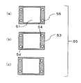
- FIG. 26 shows a plate-like member 55 as a constituent member of the mixed gas layer 5.
- the intralayer communication channel member having the intralayer communication channel 54 shown in FIG. 5 can be easily constructed by superimposing the intra-layer flow path members (a) and (c) that do not have the intra-layer communication flow path 54 on both sides of (b).
- the permeate gas layer 6 in FIG. 6 is also obtained by turning over the same plate-shaped member.
- FIG. 27 shows another example of a plate-like member 55 as a constituent member of the mixed gas layer 5.
- the mixed gas channel 51 is configured by laminating seven members (a) to (g) in this order. That is, the hydrogen permeation part corresponding region 51 is made of a soft material suitable for sealing having a fine through-hole in the hydrogen permeation part corresponding region 51.
- the mixed gas layer 5 can be constructed by combining the plate-like members 551 to 554 having different structures (a) to (g).
- the permeated gas layer 6 can also be obtained by turning over the same laminated plate members 551 to 554 of (a) to (g).
- a hydrogen separation device having a large effective membrane area per one hydrogen separation layer and capable of withstanding a large pressure difference is obtained.
- the divided parts of the hydrogen separation layer support / in-layer flow path member 552 and the hydrogen separation layer support / in-layer flow path member 554 are orthogonal to each other. It becomes a space at 553, and there is room for the thickness.
- the laminate when the laminate is integrated, no pressure is applied in the stacking direction, and the hydrogen separation layer 4 and the hydrogen separation layer supporting / sealing member 551 are not in close contact with each other. That is, they are not joined and are not bound to each other. By doing so, the laminate can be easily integrated without damaging the hydrogen separation layer 4.
- Example 1 A mixed gas layer produced by superimposing the plate-like members 55 (a) to (g) shown in FIG. 28 in this order using one pure Pd membrane having a thickness of 200 ⁇ m as a hydrogen separation layer, and the mixed gas The layers were sandwiched between the permeated gas layers formed by turning them over.
- the width in the in-plane direction of the in-layer communication channel 54 formed on the plate-shaped member (d) is 0.6 mm, and the effective membrane area for hydrogen permeation is 2.4 cm 2 .
- the plate-like member 55 of (b) and (f) as the in-layer flow path member and the plate-like member 55 of (d) as the in-layer communication flow path member are both sealed with SUS430 having a thickness of 0.5 mm. Ni having a thickness of 0.2 mm was used for the plate-like member 55 of (a), (c), (e), and (g) as a member.
- the laminated hydrogen separation layer, mixed gas layer, and permeate gas layer were sandwiched between 20 mm thick SUS430 end plates with piping, and tightened with 6 Nmm bolts with a torque of 32 Nm from both sides using a jig. This was heat treated in an atmosphere of 95% Ar-5% H 2 at 700 ° C. for 1 hour, thereby diffusion bonding to produce an integrated laminate.
- This laminated body is stored in a container so that a buffer space is formed at both end surfaces in the laminating direction, and a mixed gas introduction pipe, a sweep gas introduction pipe, and a permeate gas discharge pipe are connected between the flow path in the laminated body and the outside of the container.
- the mixed gas that did not permeate the hydrogen separation layer was led out of the container through the buffer space in the container.
- Example 1 The same laminate as that of Example 1 was assembled, and the laminate was integrated by diffusion bonding under the same conditions.
- This laminated body is stored in a container so that buffer spaces are formed at both end surfaces in the laminating direction, and all of the mixed gas introduction pipe, the sweep gas introduction pipe, the permeate gas discharge pipe, and the mixed gas discharge pipe are flow paths in the laminate. And connected outside the container. For safety, the container was sealed but filled with air at atmospheric pressure. The pressure in the container is about 200 kPa at the operating temperature of 300 ° C.
- Example 2 Using four Pd 75 Ag 25 membranes (subscript is atomic%) with a thickness of 20 ⁇ m as hydrogen separation layers, the plate members 55 (a) to (g) shown in FIG. 29 are laminated in this order. The mixed gas layer and the permeated gas layer formed by turning the mixed gas layer upside down were stacked.
- the plate-like member 55 of (b) to (f) is the same as that of FIG. 28, and the plate-like member 55 of (a) and (g) as a hydrogen separation layer supporting and sealing member has a thickness of 0.3 mm. Ni having many fine through-holes with a diameter of 0.35 mm in the hydrogen permeation portion corresponding region was used.
- the stacked hydrogen separation layer, mixed gas layer, and permeate gas layer were sandwiched between 20 mm thick end plates with SUS430 pipes, and tightened with six 8 mm diameter bolts with a torque of 32 Nm from both sides using a jig. This was heat treated in an atmosphere of 95% Ar-5% H 2 at 700 ° C. for 1 hour, thereby diffusion bonding to produce an integrated laminate.
- the effective membrane area for hydrogen permeation is 9.6 cm 2 (2.4 cm 2 per hydrogen separation layer).
- This laminate is placed in a container so that a buffer space is formed at both end faces in the stacking direction, and the sweep gas introduction pipe, permeate gas discharge pipe, and mixed gas discharge pipe are connected between the flow path in the laminate and the outside of the container. Then, the mixed gas was guided to the mixed gas flow path in the laminate through the buffer space in the container.
- a mixed gas (73.4% H 2 , 23.8% CO 2 , 2.8% CO) was introduced into the mixed gas flow path at 900 kPa. Meanwhile, the pressure of the permeating gas channel was set to atmospheric pressure (100 kPa). After 40 hours, 53 mL / min of hydrogen was obtained from the permeate gas discharge pipe. The components were examined by gas chromatography, but no impurities were detected and it was found that at least 99.99% pure hydrogen was obtained. From this, it was confirmed that according to the present invention, even when the thin hydrogen separation layer having a thickness of 20 ⁇ m was formed, the laminate did not collapse for a long time and high purity hydrogen was obtained.
- Example 3 Using a Pd 75 Ag 25 membrane with a thickness of 20 ⁇ m as eight hydrogen separation layers, the mixed gas layer produced by superimposing the seven members (a) to (g) shown in FIG. The gas layer was laminated between the permeated gas layer formed by turning it over.
- the width in the in-plane direction of the in-layer communication channel 54 formed in (d) which is the hydrogen separation layer supporting and in-layer communication channel member 554 is 0.6 mm.
- the hydrogen separation layer support and in-layer flow path member 552 (b), (f) and the hydrogen separation layer support and in-layer flow path member 554 (d) are both made of SUS430 having a thickness of 0.5 mm.
- the support member sealing member 553 (c), (e) is 0.2 mm thick Ni, and the hydrogen separation layer support / seal member 551 (a), (g) is 0. Ni having many fine through-holes having a diameter of 0.35 mm in the region corresponding to the hydrogen permeation portion at 3 mm was used.
- SUS430 having a thickness of 10 mm was used for the end plate with piping, and the piping connecting the flow path in the laminate and the outside of the container was designed to be connected to a surface perpendicular to the end surface in the stacking direction of the laminate.
- the laminated hydrogen separation layer, mixed gas layer, and permeate gas layer were sandwiched between an end plate with piping and an end plate of SUS430 having a thickness of 5 mm, and tightened with a torque of 65 Nm from both sides with six 10 mm diameter bolts using a jig. .
- the effective membrane area for hydrogen permeation is 81 cm 2 (10.1 cm 2 per hydrogen separation layer).
- This laminate was placed in a container so that buffer spaces were formed on both end faces in the lamination direction.
- the mixed gas introduction pipe was directly connected to the container wall so as to communicate with the buffer space, and the end plate was provided with a through hole communicating with the mixed gas flow path. That is, the introduced mixed gas reaches the mixed gas flow path through the mixed gas introduction pipe, the buffer space, and the through hole.
- the mixed gas discharge pipe and the permeate gas discharge pipe connected to the laminate are connected to the outside of the container.
- the size of the hydrogen separator assembled in this way was 96 cm 3 (width 64 mm ⁇ height 44 mm ⁇ depth 34 mm) excluding piping outside the apparatus.
- FIG. 30 shows a perspective view of the hydrogen separator used in Example 3
- FIG. 31 shows a top view
- FIGS. 32 and 33 show a cross section AB and a CD cross section of FIG.
- the hydrogen separator has a configuration similar to that of the fifth embodiment in that there is no pipe for introducing the sweep gas, and the pipe is connected to a plane perpendicular to the end face in the stacking direction.
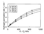
- FIG. 34 shows the relationship between the difference between the pressure (P f ) of the mixed gas channel and the pressure (P p ) of the permeate gas channel and the hydrogen flow rate obtained from the permeate gas discharge pipe at that time.
- FIG. 35 shows the result of analyzing the gas obtained from the mixed gas discharge pipe and the permeate gas discharge pipe after 30 minutes using a gas chromatograph.
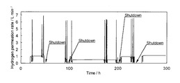
- FIG. 36 shows the relationship between the operation time in these tests and the hydrogen flow rate obtained from the permeate gas discharge pipe.
- the hydrogen separator was stopped and restarted four times in total.
- the permeate gas discharge pipe was connected to the pipe through which Ar flows, and pure Ar was introduced into the mixed gas flow path at a flow rate of 0.2 L / min and atmospheric pressure (100 kPa), and the furnace was cooled to room temperature.
- the test was continued after the time shown in FIG. 36, and the hydrogen permeation test was conducted for a total of 467 hours, and then the mixed gas (73.4% H 2 , 23.8% CO 2 , 2 .8% CO) was introduced at 300 kPa. Meanwhile, the pressure of the permeating gas channel was set to atmospheric pressure (100 kPa).
- Example 2 Comparative Example 2
- a hydrogen separator having the same configuration as in Example 3 was assembled using six hydrogen separation layers. At that time, eight bolt through holes were provided on the peripheral edge of the end plate and assembled using eight 10 mm diameter bolts.
- the hydrogen separator according to the present invention is excellent in durability and performance, and can be downsized and reduced in cost. Therefore, the fuel cell system for commercial fuel cells, household fuel cells, fuel cell vehicles, etc. In addition, it can be effectively used as a hydrogen separator in a field where various types of hydrogen are required, such as a chemical plant.
Landscapes
- Chemical & Material Sciences (AREA)
- Organic Chemistry (AREA)
- Engineering & Computer Science (AREA)
- Chemical Kinetics & Catalysis (AREA)
- Combustion & Propulsion (AREA)
- Inorganic Chemistry (AREA)
- Analytical Chemistry (AREA)
- General Chemical & Material Sciences (AREA)
- Oil, Petroleum & Natural Gas (AREA)
- Separation Using Semi-Permeable Membranes (AREA)
- Hydrogen, Water And Hydrids (AREA)
Abstract
Description
このように構成された積層型の水素分離装置は、コンパクトな装置に多数の水素透過膜を組込むことが可能となり、多くの水素を回収することが可能となる。
(1)水素を選択的に透過させる水素分離層、水素分離層の一方の面に隣接する混合ガス層であって、水素含有ガスが流れる混合ガス流路と、表面に露出する混合ガス流路の全周を囲み、水素分離層に密接するシール部とを有する混合ガス層、及び、水素分離層の他方の面に隣接する透過ガス層であって、水素分離層を透過した水素が流れる透過ガス流路と、表面に露出する透過ガス流路の全周を囲み、水素分離層に密接するシール部とを有する透過ガス層を積層し一体化して得られる積層体と、積層体を内包しバッファーガスを満たした容器を具備し、積層体と容器の内壁の間には積層体の積層方向の少なくとも一方の端面においてバッファーガスが到達しうるバッファー空間が設けられており、かつ、バッファー空間の圧力が混合ガス流路と透過ガス流路のうち高い方の圧力と等しいかそれより高い水素分離装置。
(2)上記混合ガス流路と上記透過ガス流路のうち圧力の高い方とバッファー空間が連通している上記(1)に記載の水素分離装置。
(3)上記混合ガス流路がバッファー空間と連通している上記(1)に記載の水素分離装置。
(4)水素含有ガスが上記バッファー空間を経て上記混合ガス流路に流れる上記(1)に記載の水素分離装置。
(5)上記積層体に連結し、積層体内の流路と容器外をつなぐ配管が2本である上記(1)に記載の水素分離装置。
(6)積層体内の流路と容器外をつなぐ配管が積層体の積層方向の端面に対し直角の面に連結している上記(1)に記載の水素分離装置。
(7)積層体は、混合ガス層や透過ガス層より層厚が大きい配管連結用プレートを含み、積層体内の流路と容器外をつなぐ配管が該配管連結用プレートの周囲の面に連結している上記(6)に記載の水素分離装置。
(8)上記混合ガス層及び上記透過ガス層の水素分離層と密接するシール部に設けられ、上記混合ガス層又は上記透過ガス層の水素透過部対応領域と連通し、水素透過部対応領域に対しガスを導入又は導出する層内連絡流路に、その層内方向の幅が1mm以下の部分を有する上記(1)に記載の水素分離装置。
(9)上記混合ガス層及び上記透過ガス層の少なくとも一方が複数枚の板状部材から構成されており、前記層を構成する少なくとも1枚の板状部材は上記層内連絡流路を有し、かつ、この板状部材の水素透過部対応領域を平面的には連通しないよう流路が分割されている上記(1)に記載の水素分離装置。
(10)上記水素透過部対応領域において、隣接する水素分離層と混合ガス層及び透過ガス層を構成する板状部材が密接していない上記(9)に記載の水素分離装置。
(実施例1)
厚さ200μmの純Pd膜を水素分離層として1枚用い、図28に示す(a)~(g)の板状部材55をこの順番で重ね合わせて作製された混合ガス層と、該混合ガス層を裏返して形成された透過ガス層との間に挟んで積層した。
(比較例1)
実施例1と同じ積層物を組み立て、同じ条件で拡散接合して一体化した積層体を作製した。この積層体をその積層方向の両端面においてバッファー空間が形成されるように容器に収め、混合ガス導入配管、スイープガス導入配管、透過ガス排出配管、混合ガス排出配管の全てを積層体内の流路と容器外の間で接続した。安全のため、容器は密封したが、大気圧の空気で満たした。容器内の圧力は運転温度の300℃で約200kPaとなる。
(実施例2)
厚さ20μmのPd75Ag25膜(下付添字は原子%)を水素分離層として4枚用い、図29に示す(a)~(g)の板状部材55をこの順番で重ね合わせて作製した混合ガス層と、該混合ガス層を裏返して形成した透過ガス層との間に挟んで積層した。(b)~(f)の板状部材55は図28のものと同じで、水素分離層支持兼シール部材としての(a)、(g)の板状部材55には厚さ0.3mmで水素透過部対応領域に直径0.35mmの微細な貫通孔を多数有するNiを使用した。
(実施例3)
厚さ20μmのPd75Ag25膜を水素分離層として8枚用い、図27に示す(a)~(g)の7つの部材を、この順番で重ね合わせて作製した混合ガス層と、該混合ガス層を裏返して形成した透過ガス層との間に挟んで積層した。水素分離層支持兼層内連絡流路部材554である(d)に形成された層内連絡流路54の面内方向の幅は0.6mmとなっている。
(比較例2)
水素分離層6枚を用い、実施例3と同様の構成の水素分離装置を組み立てた。その際、端板の周縁部に8ヶ所のボルト用貫通孔を設け、10mm径のボルト8本を用いて組み立てた。この場合ボルト用の貫通孔を設けるため、混合ガス層、透過ガス層及び水素分離層をより大きな端板を使用した。こうして組み立てた水素分離装置の大きさは、装置外の配管を除いて640cm3(幅100mm×高さ80mm×奥行き80mm)であり、実施例3の5倍以上であった。
11:バッファー空間
2:配管
21:混合ガス導入配管
22:スイープガス導入配管
23:混合ガス排出配管
24:透過ガス排出配管
25:バッファーガス導入配管
3:積層体
4:水素分離層
41:水素透過部
43:シール部
46:貫通孔(層間連通孔用貫通孔)
5:混合ガス層
51:混合ガス流路水素透過部対応領域
53:シール部
54:混合ガス流路層内連絡流路
55:構成部材(板状部材)
551:水素分離層支持兼シール部材
552:水素分離層支持兼層内流路部材
553:支持部材間シール部材
554:水素分離層支持兼層内連絡流路部材
56:貫通孔(層間連通孔用貫通孔)
6:透過ガス層
61:透過ガス流路水素透過部対応領域
63:シール部
64:透過ガス流路層内連絡流路
65:構成部材(板状部材)
66:貫通孔(層間連通孔用貫通孔)
7:端板
71:配管連結用プレート
8:層間連通孔
Claims (10)
- 水素を選択的に透過させる水素分離層、水素分離層の一方の面に隣接する混合ガス層であって、水素含有ガスが流れる混合ガス流路と、表面に露出する混合ガス流路の全周を囲み、水素分離層に密接するシール部とを有する混合ガス層、及び、水素分離層の他方の面に隣接する透過ガス層であって、水素分離層を透過した水素が流れる透過ガス流路と、表面に露出する透過ガス流路の全周を囲み、水素分離層に密接するシール部とを有する透過ガス層を積層し一体化して得られる積層体と、
積層体を内包しバッファーガスを満たした容器を具備し、
積層体と容器の内壁の間には積層体の積層方向の少なくとも一方の端面においてバッファーガスが到達しうるバッファー空間が設けられており、
かつ、バッファー空間の圧力が混合ガス流路と透過ガス流路のうち高い方の圧力と等しいかそれより高い水素分離装置。 - 上記混合ガス流路と上記透過ガス流路のうち圧力の高い方とバッファー空間が連通している請求項1に記載の水素分離装置。
- 上記混合ガス流路がバッファー空間と連通している請求項1に記載の水素分離装置。
- 水素含有ガスが上記バッファー空間を経て上記混合ガス流路に流れる請求項1に記載の水素分離装置。
- 上記積層体に連結し、積層体内の流路と容器外をつなぐ配管が2本である請求項1に記載の水素分離装置。
- 積層体内の流路と容器外をつなぐ配管が積層体の積層方向の端面に対し直角の面に連結している請求項1に記載の水素分離装置。
- 積層体は、混合ガス層や透過ガス層より層厚が大きい配管連結用プレートを含み、積層体内の流路と容器外をつなぐ配管が該配管連結用プレートの周囲の面に連結している請求項6に記載の水素分離装置。
- 上記混合ガス層及び上記透過ガス層の水素分離層と密接するシール部に設けられ、上記混合ガス層又は上記透過ガス層の水素透過部対応領域と連通し、水素透過部対応領域に対しガスを導入又は導出する層内連絡流路に、その層内方向の幅が1mm以下の部分を有する請求項1に記載の水素分離装置。
- 上記混合ガス層及び上記透過ガス層の少なくとも一方が複数枚の板状部材から構成されており、前記層を構成する少なくとも1枚の板状部材は上記層内連絡流路を有し、かつ、この板状部材の水素透過部対応領域を平面的には連通しないよう流路が分割されている請求項1に記載の水素分離装置。
- 上記水素透過部対応領域において、隣接する水素分離層と混合ガス層及び透過ガス層を構成する板状部材が密接していない請求項9に記載の水素分離装置。
Priority Applications (3)
| Application Number | Priority Date | Filing Date | Title |
|---|---|---|---|
| CN201180059289.9A CN103260728B (zh) | 2010-12-14 | 2011-12-13 | 氢分离装置 |
| JP2012548790A JP5831888B2 (ja) | 2010-12-14 | 2011-12-13 | 水素分離装置 |
| US13/993,937 US9132381B2 (en) | 2010-12-14 | 2011-12-13 | Hydrogen separation device |
Applications Claiming Priority (2)
| Application Number | Priority Date | Filing Date | Title |
|---|---|---|---|
| JP2010277869 | 2010-12-14 | ||
| JP2010-277869 | 2010-12-14 |
Publications (1)
| Publication Number | Publication Date |
|---|---|
| WO2012081576A1 true WO2012081576A1 (ja) | 2012-06-21 |
Family
ID=46244675
Family Applications (1)
| Application Number | Title | Priority Date | Filing Date |
|---|---|---|---|
| PCT/JP2011/078789 Ceased WO2012081576A1 (ja) | 2010-12-14 | 2011-12-13 | 水素分離装置 |
Country Status (5)
| Country | Link |
|---|---|
| US (1) | US9132381B2 (ja) |
| JP (1) | JP5831888B2 (ja) |
| CN (1) | CN103260728B (ja) |
| TW (1) | TWI523679B (ja) |
| WO (1) | WO2012081576A1 (ja) |
Cited By (2)
| Publication number | Priority date | Publication date | Assignee | Title |
|---|---|---|---|---|
| WO2026034027A1 (ja) * | 2024-08-05 | 2026-02-12 | 住友化学株式会社 | 分離膜モジュールおよび流体分離方法 |
| WO2026034025A1 (ja) * | 2024-08-07 | 2026-02-12 | 住友化学株式会社 | プレートアンドフレーム型の分離膜エレメントおよび分離装置 |
Families Citing this family (6)
| Publication number | Priority date | Publication date | Assignee | Title |
|---|---|---|---|---|
| CN105056715A (zh) * | 2015-08-20 | 2015-11-18 | 章涛 | 一种氢气分离装置 |
| US10137665B2 (en) * | 2016-01-14 | 2018-11-27 | Tokyo Ohka Kogyo Co., Ltd. | Method for manufacturing laminate, and laminate |
| CN110441101B (zh) * | 2018-05-04 | 2022-07-01 | 研能科技股份有限公司 | 气相层析设备的分离系统 |
| KR102078591B1 (ko) * | 2018-08-28 | 2020-02-19 | 한국전력공사 | 가스분리용 평판형 분리막 모듈 |
| CN110975533B (zh) * | 2019-12-27 | 2020-11-17 | 北京东方华氢科技有限公司 | 一种提纯器 |
| CN111729479A (zh) * | 2020-07-29 | 2020-10-02 | 苏州高迈新能源有限公司 | 一种钯膜组件以及提纯器 |
Citations (3)
| Publication number | Priority date | Publication date | Assignee | Title |
|---|---|---|---|---|
| JPS494158B1 (ja) * | 1968-08-05 | 1974-01-30 | ||
| JPS6427620A (en) * | 1987-07-24 | 1989-01-30 | Chiyoda Chem Eng Construct Co | Flat membrane type gas separating device |
| JP2010240637A (ja) * | 2009-03-14 | 2010-10-28 | Tokyo Gas Co Ltd | Nb膜、周期律表5A族金属合金膜を使用した水素分離システム |
Family Cites Families (20)
| Publication number | Priority date | Publication date | Assignee | Title |
|---|---|---|---|---|
| US3344586A (en) * | 1965-06-22 | 1967-10-03 | Engelhard Ind Inc | Gas separation apparatus |
| JPS494158A (ja) | 1972-04-28 | 1974-01-14 | ||
| US6419726B1 (en) * | 1999-10-21 | 2002-07-16 | Ati Properties, Inc. | Fluid separation assembly and fluid separation module |
| JP4815668B2 (ja) | 2000-05-15 | 2011-11-16 | トヨタ自動車株式会社 | 水素生成装置 |
| US6569227B2 (en) | 2001-09-27 | 2003-05-27 | Idatech, Llc | Hydrogen purification devices, components and fuel processing systems containing the same |
| JP4806867B2 (ja) | 2001-07-23 | 2011-11-02 | トヨタ自動車株式会社 | 水素抽出装置 |
| US6660069B2 (en) * | 2001-07-23 | 2003-12-09 | Toyota Jidosha Kabushiki Kaisha | Hydrogen extraction unit |
| JP4910261B2 (ja) | 2001-09-07 | 2012-04-04 | トヨタ自動車株式会社 | 積層構造の水素分離装置 |
| US8172913B2 (en) * | 2002-04-23 | 2012-05-08 | Vencill Thomas R | Array of planar membrane modules for producing hydrogen |
| DE10235419B4 (de) * | 2002-08-02 | 2005-02-10 | Daimlerchrysler Ag | Membranmodul zur Wasserstoffabtrennung und Verfahren zu dessen Herstellung |
| US6764787B2 (en) * | 2002-09-10 | 2004-07-20 | Utc Fuel Cells, Llc | One piece sleeve gas manifold for cell stack assemblies such as fuel cells |
| WO2004060539A1 (en) * | 2002-12-19 | 2004-07-22 | Exxonmobil Upstream Research Company | Membrane module for separation of fluids |
| JP4440216B2 (ja) * | 2004-02-10 | 2010-03-24 | 三菱電機株式会社 | 温度湿度交換器 |
| JP4312624B2 (ja) * | 2004-02-13 | 2009-08-12 | 三菱電機株式会社 | 温度湿度交換器 |
| JP2005288290A (ja) | 2004-03-31 | 2005-10-20 | National Institute Of Advanced Industrial & Technology | 水素分離精製装置 |
| JP4270014B2 (ja) | 2004-04-08 | 2009-05-27 | トヨタ自動車株式会社 | 水素分離膜モジュール,水素分離膜型燃料電池、および、それらの製造方法 |
| FR2873935B1 (fr) * | 2004-08-06 | 2006-11-03 | Cie D Etudes Des Technologies | Systeme etage de production d'hydrogene purifie, a partir d'un melange gazeux reactionnel comprenant un compose hydrocarbone |
| US7771519B2 (en) * | 2005-01-03 | 2010-08-10 | Air Products And Chemicals, Inc. | Liners for ion transport membrane systems |
| US7972420B2 (en) * | 2006-05-22 | 2011-07-05 | Idatech, Llc | Hydrogen-processing assemblies and hydrogen-producing systems and fuel cell systems including the same |
| KR101285568B1 (ko) * | 2011-11-01 | 2013-07-15 | 한국에너지기술연구원 | 수소분리용 다층 모듈 |
-
2011
- 2011-12-13 US US13/993,937 patent/US9132381B2/en not_active Expired - Fee Related
- 2011-12-13 TW TW100145918A patent/TWI523679B/zh not_active IP Right Cessation
- 2011-12-13 JP JP2012548790A patent/JP5831888B2/ja not_active Expired - Fee Related
- 2011-12-13 WO PCT/JP2011/078789 patent/WO2012081576A1/ja not_active Ceased
- 2011-12-13 CN CN201180059289.9A patent/CN103260728B/zh not_active Expired - Fee Related
Patent Citations (3)
| Publication number | Priority date | Publication date | Assignee | Title |
|---|---|---|---|---|
| JPS494158B1 (ja) * | 1968-08-05 | 1974-01-30 | ||
| JPS6427620A (en) * | 1987-07-24 | 1989-01-30 | Chiyoda Chem Eng Construct Co | Flat membrane type gas separating device |
| JP2010240637A (ja) * | 2009-03-14 | 2010-10-28 | Tokyo Gas Co Ltd | Nb膜、周期律表5A族金属合金膜を使用した水素分離システム |
Cited By (2)
| Publication number | Priority date | Publication date | Assignee | Title |
|---|---|---|---|---|
| WO2026034027A1 (ja) * | 2024-08-05 | 2026-02-12 | 住友化学株式会社 | 分離膜モジュールおよび流体分離方法 |
| WO2026034025A1 (ja) * | 2024-08-07 | 2026-02-12 | 住友化学株式会社 | プレートアンドフレーム型の分離膜エレメントおよび分離装置 |
Also Published As
| Publication number | Publication date |
|---|---|
| CN103260728A (zh) | 2013-08-21 |
| TW201231145A (en) | 2012-08-01 |
| TWI523679B (zh) | 2016-03-01 |
| US9132381B2 (en) | 2015-09-15 |
| US20130333569A1 (en) | 2013-12-19 |
| CN103260728B (zh) | 2015-11-25 |
| JP5831888B2 (ja) | 2015-12-09 |
| JPWO2012081576A1 (ja) | 2014-05-22 |
Similar Documents
| Publication | Publication Date | Title |
|---|---|---|
| JP5831888B2 (ja) | 水素分離装置 | |
| US8465569B2 (en) | Membrane support module for permeate separation in a fuel cell | |
| US6660069B2 (en) | Hydrogen extraction unit | |
| US8110022B2 (en) | Hydrogen purifier module and method for forming the same | |
| JP6283233B2 (ja) | 燃料電池 | |
| SE526425C2 (sv) | Membranseparationsmodul, membranseperationskonstruktion, separationsförfarande samt förfarande för att tillverka en membranseparationskonstruktion | |
| JP4181128B2 (ja) | 流体分離用の膜モジュール | |
| KR20130048026A (ko) | 수소분리용 다층 모듈 | |
| US8226750B2 (en) | Hydrogen purifier module with membrane support | |
| JP2007007565A (ja) | 水素透過膜補強構造体及びその作製方法 | |
| JP2003144859A (ja) | ガス分離装置 | |
| KR100668647B1 (ko) | 수소정제모듈 | |
| JP4512863B2 (ja) | 水素分離透過膜とその製造方法と水素生成分離装置 | |
| JP2005288290A (ja) | 水素分離精製装置 | |
| JP5212888B2 (ja) | 水素分離体及び水素分離装置 | |
| KR20230132791A (ko) | 멤브레인 부착 기술 | |
| JPH01288303A (ja) | 流体分離素子 | |
| JP2008080234A (ja) | 複合多層構造の水素透過膜とその製造方法 | |
| JP6488732B2 (ja) | 燃料電池スタック | |
| JP4514651B2 (ja) | 燃料電池セパレータのチャネル構造 | |
| JP2006021129A (ja) | 水素透過分離材およびその製造方法 | |
| WO2018020684A1 (ja) | 燃料電池 | |
| JP2007117843A (ja) | 流体透過性薄膜構造体及びその製造方法 | |
| JP2009095729A (ja) | 酸素濃縮方法 | |
| JPH06246124A (ja) | 気体分離膜モジュール |
Legal Events
| Date | Code | Title | Description |
|---|---|---|---|
| 121 | Ep: the epo has been informed by wipo that ep was designated in this application |
Ref document number: 11848067 Country of ref document: EP Kind code of ref document: A1 |
|
| ENP | Entry into the national phase |
Ref document number: 2012548790 Country of ref document: JP Kind code of ref document: A |
|
| NENP | Non-entry into the national phase |
Ref country code: DE |
|
| WWE | Wipo information: entry into national phase |
Ref document number: 13993937 Country of ref document: US |
|
| 122 | Ep: pct application non-entry in european phase |
Ref document number: 11848067 Country of ref document: EP Kind code of ref document: A1 |