WO2012081515A1 - 治療用処置装置 - Google Patents
治療用処置装置 Download PDFInfo
- Publication number
- WO2012081515A1 WO2012081515A1 PCT/JP2011/078543 JP2011078543W WO2012081515A1 WO 2012081515 A1 WO2012081515 A1 WO 2012081515A1 JP 2011078543 W JP2011078543 W JP 2011078543W WO 2012081515 A1 WO2012081515 A1 WO 2012081515A1
- Authority
- WO
- WIPO (PCT)
- Prior art keywords
- heat
- heat transfer
- frequency
- flexible substrate
- frequency electrode
- Prior art date
- Legal status (The legal status is an assumption and is not a legal conclusion. Google has not performed a legal analysis and makes no representation as to the accuracy of the status listed.)
- Ceased
Links
Images






Classifications
-
- A—HUMAN NECESSITIES
- A61—MEDICAL OR VETERINARY SCIENCE; HYGIENE
- A61B—DIAGNOSIS; SURGERY; IDENTIFICATION
- A61B18/00—Surgical instruments, devices or methods for transferring non-mechanical forms of energy to or from the body
- A61B18/04—Surgical instruments, devices or methods for transferring non-mechanical forms of energy to or from the body by heating
- A61B18/12—Surgical instruments, devices or methods for transferring non-mechanical forms of energy to or from the body by heating by passing a current through the tissue to be heated, e.g. high-frequency current
- A61B18/14—Probes or electrodes therefor
-
- A—HUMAN NECESSITIES
- A61—MEDICAL OR VETERINARY SCIENCE; HYGIENE
- A61B—DIAGNOSIS; SURGERY; IDENTIFICATION
- A61B18/00—Surgical instruments, devices or methods for transferring non-mechanical forms of energy to or from the body
- A61B18/04—Surgical instruments, devices or methods for transferring non-mechanical forms of energy to or from the body by heating
- A61B18/08—Surgical instruments, devices or methods for transferring non-mechanical forms of energy to or from the body by heating by means of electrically-heated probes
- A61B18/082—Probes or electrodes therefor
- A61B18/085—Forceps, scissors
-
- A—HUMAN NECESSITIES
- A61—MEDICAL OR VETERINARY SCIENCE; HYGIENE
- A61B—DIAGNOSIS; SURGERY; IDENTIFICATION
- A61B18/00—Surgical instruments, devices or methods for transferring non-mechanical forms of energy to or from the body
- A61B18/04—Surgical instruments, devices or methods for transferring non-mechanical forms of energy to or from the body by heating
- A61B18/12—Surgical instruments, devices or methods for transferring non-mechanical forms of energy to or from the body by heating by passing a current through the tissue to be heated, e.g. high-frequency current
- A61B18/14—Probes or electrodes therefor
- A61B18/1442—Probes having pivoting end effectors, e.g. forceps
- A61B18/1445—Probes having pivoting end effectors, e.g. forceps at the distal end of a shaft, e.g. forceps or scissors at the end of a rigid rod
-
- A—HUMAN NECESSITIES
- A61—MEDICAL OR VETERINARY SCIENCE; HYGIENE
- A61B—DIAGNOSIS; SURGERY; IDENTIFICATION
- A61B18/00—Surgical instruments, devices or methods for transferring non-mechanical forms of energy to or from the body
- A61B2018/00571—Surgical instruments, devices or methods for transferring non-mechanical forms of energy to or from the body for achieving a particular surgical effect
- A61B2018/00589—Coagulation
-
- A—HUMAN NECESSITIES
- A61—MEDICAL OR VETERINARY SCIENCE; HYGIENE
- A61B—DIAGNOSIS; SURGERY; IDENTIFICATION
- A61B18/00—Surgical instruments, devices or methods for transferring non-mechanical forms of energy to or from the body
- A61B2018/00571—Surgical instruments, devices or methods for transferring non-mechanical forms of energy to or from the body for achieving a particular surgical effect
- A61B2018/00595—Cauterization
-
- A—HUMAN NECESSITIES
- A61—MEDICAL OR VETERINARY SCIENCE; HYGIENE
- A61B—DIAGNOSIS; SURGERY; IDENTIFICATION
- A61B18/00—Surgical instruments, devices or methods for transferring non-mechanical forms of energy to or from the body
- A61B2018/00571—Surgical instruments, devices or methods for transferring non-mechanical forms of energy to or from the body for achieving a particular surgical effect
- A61B2018/00601—Cutting
-
- A—HUMAN NECESSITIES
- A61—MEDICAL OR VETERINARY SCIENCE; HYGIENE
- A61B—DIAGNOSIS; SURGERY; IDENTIFICATION
- A61B18/00—Surgical instruments, devices or methods for transferring non-mechanical forms of energy to or from the body
- A61B2018/00636—Sensing and controlling the application of energy
- A61B2018/00773—Sensed parameters
- A61B2018/00791—Temperature
-
- A—HUMAN NECESSITIES
- A61—MEDICAL OR VETERINARY SCIENCE; HYGIENE
- A61B—DIAGNOSIS; SURGERY; IDENTIFICATION
- A61B18/00—Surgical instruments, devices or methods for transferring non-mechanical forms of energy to or from the body
- A61B18/04—Surgical instruments, devices or methods for transferring non-mechanical forms of energy to or from the body by heating
- A61B18/12—Surgical instruments, devices or methods for transferring non-mechanical forms of energy to or from the body by heating by passing a current through the tissue to be heated, e.g. high-frequency current
- A61B18/14—Probes or electrodes therefor
- A61B18/1442—Probes having pivoting end effectors, e.g. forceps
- A61B2018/1452—Probes having pivoting end effectors, e.g. forceps including means for cutting
- A61B2018/1455—Probes having pivoting end effectors, e.g. forceps including means for cutting having a moving blade for cutting tissue grasped by the jaws
-
- A—HUMAN NECESSITIES
- A61—MEDICAL OR VETERINARY SCIENCE; HYGIENE
- A61B—DIAGNOSIS; SURGERY; IDENTIFICATION
- A61B2218/00—Details of surgical instruments, devices or methods for transferring non-mechanical forms of energy to or from the body
- A61B2218/001—Details of surgical instruments, devices or methods for transferring non-mechanical forms of energy to or from the body having means for irrigation and/or aspiration of substances to and/or from the surgical site
- A61B2218/002—Irrigation
Definitions
- the present invention relates to a therapeutic treatment apparatus.
- Patent Document 1 discloses the following therapeutic treatment apparatus. That is, this therapeutic treatment apparatus has an openable / closable holding part that holds a biological tissue to be treated. A high-frequency electrode for applying a high-frequency voltage and a heater member for heating the high-frequency electrode are disposed at a portion of the holding portion that contacts the living tissue. The holding unit is provided with a cutter.
- a living tissue is grasped by a holding part and a high frequency voltage is applied. Furthermore, the living tissue is anastomosed by heating the living tissue with the holding member. Moreover, it is also possible to excise in the state which joined the biological tissue edge part with the cutter with which the holding
- the lead wire for supplying power to a heater member or the like attached to a heat transfer unit that heats biological tissue such as the high-frequency electrode of the holding unit has a high temperature.
- a heat transfer unit that heats biological tissue such as the high-frequency electrode of the holding unit has a high temperature.
- the lead wire handling method needs to be considered because of the demand for downsizing of the holding part including the heat transfer part.
- an object of the present invention is to provide a therapeutic treatment apparatus in which the heat resistance and the handling method of the lead wire for supplying power to the holding unit are taken into consideration.
- a therapeutic treatment apparatus is a therapeutic treatment apparatus for heating and treating a living tissue so as to contact and transmit heat to the living tissue.
- the present invention since electric power is supplied to the holding unit using the flexible substrate, it is possible to provide a therapeutic treatment apparatus that takes into consideration the heat resistance of the lead wire that supplies power to the holding unit and the handling method.
- FIG. 1 is a schematic diagram illustrating a configuration example of a therapeutic treatment system according to the first embodiment of the present invention.
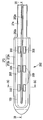
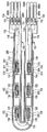
- FIG. 2A is a schematic cross-sectional view illustrating a configuration example of a shaft and a holding unit of the energy treatment device according to the first embodiment, and is a diagram illustrating a state in which the holding unit is closed.
- FIG. 2B is a schematic cross-sectional view illustrating a configuration example of the shaft and the holding unit of the energy treatment device according to the first embodiment, and is a diagram illustrating a state in which the holding unit is opened.
- FIG. 3A is a plan view illustrating an outline of a configuration example of a first holding member of the holding unit according to the first embodiment.
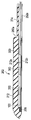
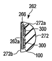
- FIG. 3B is a schematic diagram illustrating a configuration example of the first holding member of the holding unit according to the first embodiment, and is a vertical cross-sectional view taken along line 3B-3B shown in FIG. 3A.
- FIG. 3C is a schematic diagram illustrating a configuration example of the first holding member of the holding unit according to the first embodiment, and is a cross-sectional view taken along line 3C-3C illustrated in FIG. 3A.
- FIG. 4 is a diagram illustrating a configuration example of the first high-frequency electrode, the flexible substrate, the heater member, and various wirings according to the first embodiment.
- FIG. 5A is a top view illustrating an outline of a configuration example of a heater member according to each embodiment.
- FIG. 5B is a diagram schematically illustrating a configuration example of the heater member according to each embodiment, and is a cross-sectional view taken along line 5B-5B illustrated in FIG. 5A.
- FIG. 6 is a diagram illustrating a configuration example of the energy source according to the first embodiment.
- FIG. 7 is a diagram illustrating a configuration example of a first high-frequency electrode, a flexible substrate, a heater member, and various wirings according to a modification example of the first embodiment.
- FIG. 8 is a diagram illustrating a configuration example of the first high-frequency electrode, the flexible substrate, the heater member, and various wirings according to the second embodiment.
- FIG. 9 is a diagram illustrating another configuration example of the first high-frequency electrode, the flexible substrate, the heater member, and various wirings according to the second embodiment.
- FIG. 10A is a diagram illustrating a configuration example of a first high-frequency electrode, a flexible substrate, a heater member, and various wirings according to the third embodiment.
- FIG. 10B is a cross-sectional view illustrating a configuration example of the first high-frequency electrode, the flexible substrate, the heater member, and various wirings according to the third embodiment.
- the therapeutic treatment apparatus is an apparatus that causes high-frequency energy and thermal energy to act on a living tissue for use in treatment of the living tissue.
- the therapeutic treatment device 210 includes an energy treatment tool 212, an energy source 214, and a foot switch 216.
- the energy treatment tool 212 is a linear type surgical treatment tool for performing treatment by, for example, penetrating the abdominal wall.
- the energy treatment device 212 includes a handle 222, a shaft 224, and a holding portion 226.
- the holding unit 226 can be opened and closed, and is a treatment unit that holds a living tissue to be treated and performs treatment such as coagulation and incision.
- the holding part 226 is disposed at one end of the shaft 224.
- the other end of the shaft 224 is connected to the handle 222.
- the holding portion 226 side is referred to as the distal end side
- the handle 222 side is referred to as the proximal end side.
- the handle 222 is formed in a shape that is easy for an operator to grip, for example, a substantially L-shape.
- the handle 222 is connected to the energy source 214 via a cable 228.
- the shape of the energy treatment device 212 shown here is, of course, an example, and other shapes may be used as long as they have the same function.
- the shape may be a forceps or the shaft may be curved.
- a foot switch 216 having a pedal 216a is connected to the energy source 214.
- the foot switch 216 operated with a foot may be replaced with a switch operated with a hand or other switches.
- ON / OFF of the supply of energy from the energy source 214 to the energy treatment instrument 212 is switched.
- the handle 222 includes a holding portion opening / closing knob 232 and a cutter driving knob 234.
- the holding portion opening / closing knob 232 is connected to a proximal end of a sheath 244 of the shaft 224 described later.
- the sheath 244 moves along the axial direction of the shaft 224.
- the holding unit 226 opens and closes.
- the cutter driving knob 234 is provided in parallel with the holding portion opening / closing knob 232 and is a knob for moving a cutter 254 described later.
- FIGS. 2A and 2B An example of the structure of the holding part 226 and the shaft 224 is shown in FIGS. 2A and 2B.
- 2A shows a state in which the holding unit 226 is closed
- FIG. 2B shows a state in which the holding unit 226 is opened.
- the shaft 224 includes a cylindrical body 242 and a sheath 244.
- the cylindrical body 242 is fixed to the handle 222 at its proximal end.
- the sheath 244 is disposed on the outer periphery of the cylindrical body 242 so as to be slidable along the axial direction of the cylindrical body 242.
- a holding portion 226 is disposed at the distal end portion of the cylindrical body 242.
- the holding unit 226 includes a first holding member 262 and a second holding member 264. It is preferable that the first holding member 262 and the second holding member 264 each have insulation properties as a whole.
- the first holding member 262 integrally includes a first holding member main body 272 and a base portion 274 provided on the proximal end side of the first holding member main body 272.
- the second holding member 264 is integrally provided with a second holding member main body 276 and a base portion 278 provided on the base end side of the second holding member main body 276.
- the base portion 274 of the first holding member 262 is fixed to the distal end portion of the cylindrical body 242 of the shaft 224.
- the base 278 of the second holding member 264 can be rotated by a support pin 280 disposed at the tip of the cylindrical body 242 of the shaft 224 in a direction orthogonal to the axial direction of the shaft 224. It is supported. Accordingly, the second holding member 264 rotates around the axis of the support pin 280 and opens or closes with respect to the first holding member 262.
- the outer surface shapes of the first holding member 262 and the second holding member 264 are smooth curved surfaces.
- the shape is such that when the second holding member 264 is closed with respect to the first holding member 262, the combined cross section of the first holding member main body 272 and the second holding member main body 276 is substantially circular or substantially circular. It becomes elliptical.
- the cross-sectional shapes of the base portion 274 of the first holding member 262 and the base portion 278 of the second holding member 264 are also substantially circular or elliptical.
- the diameters of the first holding member main body 272 and the second holding member main body 276 are formed larger than the diameters of the base portion 274 of the first holding member 262 and the base portion 278 of the second holding member 264. ing.
- a step 282 a is formed between the first holding member main body 272 and the base 274 of the first holding member 262, and the second holding member main body 276 and the base 278 of the second holding member 264 are formed.
- a step 282b is formed between the two.
- the second holding member 264 is urged by an elastic member 280a such as a leaf spring so as to open with respect to the first holding member 262.
- an elastic member 280a such as a leaf spring
- a concave portion 246 is formed in the cylindrical body 242 along the axial direction of the cylindrical body 242.
- the recess 246 includes a first high-frequency electrode energization line 266b connected to a first high-frequency electrode 266, which will be described later, and a plurality of heater members connected to the heater member 300 that is a heat-generating member via the flexible substrate 100.
- a current carrying line 268 is provided.
- the cylindrical body 242 is connected to a heater member 300 which is a heat generating member via a second high-frequency electrode energization line 270 b connected to a second high-frequency electrode 270 described later and the flexible substrate 100.
- a plurality of heater member energization lines 269 are inserted.
- a drive rod 252 is disposed so as to be movable along the axial direction of the cylinder 242.
- a thin plate-like cutter 254 is disposed on the distal end side of the drive rod 252.
- the front end side of the cutter 254 is a free end, and a blade 254a is formed there.
- the proximal end side of the cutter 254 is fixed to the drive rod 252.
- a long groove 254 b is formed between the distal end side and the proximal end side of the cutter 254.
- the long groove 254 b passes through a movement restriction pin 256 that extends in a direction orthogonal to the axial direction of the shaft 224 and the surface direction of the cutter 254 and is fixed to the cylindrical body 242.
- the proximal end side of the drive rod 252 to which the cutter 254 is fixed is connected to the cutter drive knob 234.
- the cutter driving knob 234 When the cutter driving knob 234 is operated, the cutter 254 is moved along the axial direction of the cylindrical body 242 via the driving rod 252.
- the cutter 254 moves while being restricted by the movement restricting pin 256 and the long groove 254b.
- a movement restricting pin 256 is locked at at least three locations between one end and the other end of the long groove 254b of the cutter 254 and between the one end and the other end, and a locking portion for controlling the movement of the cutter 254. 254c is formed.
- the cutter 254 moves to the front end side, the cutter 254 is accommodated in a cutter guide groove 262a formed in a first holding member 262 and a cutter guide groove 264a formed in the second holding member 264, which will be described later.
- the fluid discharge port 242a is closed on the proximal end side of the cylindrical body 242, the fluid discharge port 244a is closed on the proximal end side of the sheath 244, and the holding portion 226 is closed ( In the state shown in FIG. 2A, the positions are matched.
- a connection cap is provided on the outer peripheral surface of the fluid discharge port 244a of the sheath 244.
- the fluids such as vapor and liquid released from the living tissue by sucking the inside of the connection base are the cutter guide grooves 262a and 264a, the inside of the cylindrical body 242, the fluid outlet 242a of the cylindrical body 242, and the fluid outlet of the sheath 244. 244a, discharged through the connection cap.
- the fluid discharge ports 242a and 244a are preferably provided in the shaft 224, but may be provided in the handle 222.
- the first holding member main body 272 and the base 274 are formed with cutter guide grooves 262a for guiding the cutter 254 described above.
- the first holding member body 272 is formed with a recess 272a and a holding surface 272b including an edge of the recess 272a.
- a first high-frequency electrode 266 made of a thin copper plate is disposed in the recess 272a. Since the first high-frequency electrode 266 has the cutter guide groove 262a, the planar shape thereof is substantially U-shaped as shown in FIG. 3A. The surface of the first high-frequency electrode 266 is in contact with the living tissue.
- the holding surface 272b comes into contact with a holding surface 276b of a second holding member 264 that faces a holding surface 272b described later.
- the first high-frequency electrode 266 does not contact a second high-frequency electrode 270 that faces the first high-frequency electrode 266 described later.
- the holding unit 226 in the closed state grips the living tissue
- the gripped living tissue is deformed according to the shape of the gap, and the first high-frequency electrode 266 and the first high-frequency electrode 266 In contact with the second high-frequency electrode 270.
- the first high-frequency electrode 266 is electrically connected to a first high-frequency electrode conducting line 266b.
- the first high-frequency electrode 266 is connected to the cable 228 via the first high-frequency electrode conducting line 266b.
- a cutter guide groove 264a is formed at a position facing the cutter guide groove 262a.
- the cutter guide groove 262 a of the first holding member 262 and the cutter guide groove 264 a of the second holding member 264 can guide the cutter 254.
- the second holding member main body 276 is provided with a second high-frequency electrode 270 having a shape symmetrical to the first high-frequency electrode 266 at a position facing the first high-frequency electrode 266.
- the second high-frequency electrode 270 is connected to the cable 228 via a second high-frequency electrode conducting line 270b.
- the first holding member main body 272 and the second holding member main body 276 further have a mechanism for heat generation in order to cauterize the living tissue in contact with the first high-frequency electrode 266 and the second high-frequency electrode 270.
- this mechanism will be described.
- the heat generating mechanism provided in the first holding member main body 272 and the heat generating mechanism provided in the second holding member main body 276 have the same form. Therefore, here, the heat generation mechanism formed in the first holding member main body 272 will be described as an example.
- the flexible substrate 100 is disposed on the surface (back surface) opposite to the surface in contact with the living tissue of the first high-frequency electrode 266.
- the flexible substrate 100 is a substrate obtained by printing wiring with copper on a substrate made of polyimide, for example.
- the flexible substrate 100 has a substantially U shape in accordance with the shape of the first high-frequency electrode 266. However, a lead portion 102 extending longer than the first high-frequency electrode 266 is formed on the base end side.
- pad portions 104 having a width wider than other portions are formed.
- Three electrodes are formed on each of the pad portions 104.
- the electrodes formed on one end are referred to as an electrode 111, an electrode 112, and an electrode 113 in order from the cutter guide groove 262a side (inner side).
- the electrodes formed on the other end are referred to as an electrode 114, an electrode 115, and an electrode 116 in order from the cutter guide groove 262a side (inner side).
- three pieces are arranged in the longitudinal direction of the first high-frequency electrode 266 in two rows at symmetrical positions across the cutter guide groove 262a.
- a hole is formed. These holes are sequentially referred to as a hole 151, a hole 152, and a hole 153 from the base side on the side where the electrode 111 is formed with respect to the cutter guide groove 262a. In addition, these holes are sequentially referred to as a hole 154, a hole 155, and a hole 156 from the base side on the side where the electrode 114 is formed with respect to the cutter guide groove 262a.
- the heater members 300 are disposed at the positions of these six holes.
- the heater member 300 will be described with reference to FIGS. 5A and 5B.
- the heater member 300 is a heat generating member that generates heat.
- the heater member 300 is formed using a substrate 311 made of alumina.
- a resistance pattern 313 that is a Pt thin film for heat generation is formed on one surface of the main surface of the substrate 311. Further, a pair of rectangular electrodes 315 connected to both ends of the resistance pattern 313 are formed on the surface of the substrate 311.
- An insulating polyimide film 317 is formed on the surface of the substrate 311 including on the resistance pattern 313 except for the portion where the electrode 315 is formed.
- a bonding metal layer 319 is formed on the entire back surface of the substrate 311.
- the electrode 315 and the bonding metal layer 319 are multilayer films made of, for example, Ti, Cu, Ni, and Au.
- the electrode 315 and the bonding metal layer 319 have stable strength against wire bonding and soldering.
- the bonding metal layer 319 is provided so that the bonding is stable when the heater member 300 is soldered to the first high-frequency electrode 266.
- the heater member 300 is fixed by soldering the surface of the bonding metal layer 319 and the back surface of the first high-frequency electrode 266, and the hole portion of the flexible substrate 100 is matched to the position of each heater member 300. Is provided.
- the heater member 300 corresponding to the hole 151 is referred to as a heater member 301.
- the heater member 300 corresponding to the hole 152 corresponds to the heater member 302, the heater member 303 corresponding to the hole 153, the heater member 304 corresponding to the hole 154, and the heater member 304 and hole 155.
- Those corresponding to the heater member 305 and those corresponding to the hole 156 will be referred to as the heater member 306, respectively.
- an electrode 121 is formed on the flexible substrate 100 at a position facing the electrode 315 disposed on the proximal end side of the heater member 301.
- an electrode 131 is formed at a position facing the electrode 315 disposed on the front end side of the heater member 301.
- electrodes 122, 123, 124, 125, and 126 are formed at positions facing the electrodes 315 disposed on the base end sides of the heater members 302, 303, 304, 305, and 306, respectively.
- Electrodes 132, 133, 134, 135, and 136 are formed at positions facing the electrodes 315 disposed on the distal ends of the heater members 302, 303, 304, 305, and 306, respectively.
- the wiring 118 is printed on the flexible substrate 100 so as to connect the electrode 111 and the electrode 121. Similarly, the electrode 112 and the electrode 122, the electrode 113 and the electrode 123, the electrode 114 and the electrode 124, the electrode 115 and the electrode 125, and the electrode 116 and the electrode 126 are connected, respectively. The wiring 118 is printed.
- wiring 118 is printed on the flexible substrate 100 so as to connect the electrode 131 and the electrode 134. Similarly, the wiring 118 is printed so that the electrode 132 and the electrode 135 may be connected, and so that the electrode 133 and the electrode 136 may be connected.
- the electrode 111 is connected to one of a plurality of heater member energization lines 268 that are general lead wires.
- the heater member energization line 268 connected to the electrode 111 is referred to as a heater member energization line 2681.
- a heater member energization line 2682 which is one of the plurality of heater member energization lines 268, is connected to the electrode 112.
- the heater member energization line 2683 is provided for the electrode 113
- the heater member energization line 2684 is provided for the electrode 114
- the heater member energization line 2585 is provided for the electrode 115
- the heater member energization line is provided for the electrode 116. 2686 are connected to each other.
- the electrode 121 of the flexible substrate 100 and the electrode 315 disposed on the proximal end side of the heater member 301 opposite to the electrode 121 are connected by a wire 351 by wire bonding.
- the electrodes 122, 123, 124, 125, 126, 131, 132, 133, 134, 135, 136 of the flexible substrate 100 and the electrodes 315 of the heater members 300 facing them are respectively wire bonded by wire bonding.
- 351 is connected.
- the heater member energization line 2681, the resistance pattern 313 of the heater member 301, the resistance pattern 313 of the heater member 304, and the heater member energization line 2684 are connected in series in this order.
- the heater member energization line 2682, the resistance pattern 313 of the heater member 302, the resistance pattern 313 of the heater member 305, and the heater member energization line 2585 are connected in series in this order.
- the heater member energization line 2683, the resistance pattern 313 of the heater member 303, the resistance pattern 313 of the heater member 306, and the heater member energization line 2686 are connected in series in this order.
- the heater member energization line 2681 and the heater member energization line 2684 to pass a current through the heater member 301 and the heater member 304.
- the proximal end side can be heated.
- the front end side of the first high-frequency electrode 266 can be heated by passing a current through the heater member 303 and the heater member 306 using the heater member energization line 2683 and the heater member energization line 2686.
- an intermediate portion of the first high-frequency electrode 266 can be heated by passing a current through the heater member 302 and the heater member 305 using the heater member energization line 2682 and the heater member energization line 2585.
- the first high-frequency electrode energization line 266b for applying a high-frequency voltage from the cable 228 to the first high-frequency electrode 266 can be connected to any portion where the first high-frequency electrode 266 is exposed.
- the size of the heater member 300 is, for example, about 3 mm in length and about 1.2 mm in width.
- the size of the first high-frequency electrode 266 is, for example, a length of about 35 mm in the longitudinal direction, a width of about 7 mm, and a cutter guide groove 262 a having a width of about 1 mm along the central axis. is there.
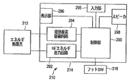
- the energy source 214 includes a control unit 290, a high frequency (HF) energy output circuit 292, a heating element driving circuit 294, an input unit 295, a display unit 296, and a speaker 298. Is arranged.
- a high-frequency energy output circuit 292, a heating element driving circuit 294, an input unit 295, a display unit 296, and a speaker 298 are connected to the control unit 290.
- the control unit 290 controls each unit of the energy source 214.
- the high frequency energy output circuit 292 is connected to the energy treatment tool 212 and drives the first high frequency electrode 266 and the second high frequency electrode 270 of the energy treatment tool 212 under the control of the control unit 290.
- the heat generating element driving circuit 294 is connected to the energy treatment device 212 and drives the heater member 300 of the energy treatment device 212 under the control of the control unit 290.
- a foot switch (SW) 216 is connected to the control unit 290. The foot switch 216 receives ON from which treatment by the energy treatment instrument 212 is performed and OFF from which treatment is stopped.
- the input unit 295 inputs various settings of the control unit 290.
- the display unit 296 displays various settings of the control unit 290.
- the speaker 298 outputs an alarm sound or the like.
- the high frequency energy output circuit 292 can output high frequency energy and detect the impedance Z. That is, the high frequency energy output circuit 292 has a sensor function of measuring the impedance Z of the living tissue between the first high frequency electrode 266 and the second high frequency electrode 270 of the energy treatment instrument 212.
- the heat generating element drive circuit 294 has a sensor function of supplying energy to the heater member 300 to cause the heater member 300 to generate heat and measuring the heat generation temperature T of the heater member 300.
- the surgeon operates the input unit 295 of the energy source 214 in advance to set the output condition of the therapeutic treatment apparatus 210.
- set power Pset [W] for high-frequency energy output, set temperature Tset [° C.] for thermal energy output, threshold values Z1 and Z2 for impedance Z of living tissue, and the like are set in advance.
- Each value may be set individually, or may be configured to select a set of setting values according to the technique.
- the holding part 226 and the shaft 224 of the energy treatment instrument 212 are inserted into the abdominal cavity through the abdominal wall, for example, with the holding part 226 closed as shown in FIG. 2A.
- the operator operates the holding unit opening / closing knob 232 of the handle 222 to grip the biological tissue to be treated, so that the first holding member 262 and the second holding member 262
- the holding member 264 is opened and closed. That is, first, the sheath 244 is moved to the proximal end side with respect to the cylindrical body 242. As a result, the second holding member 264 opens with respect to the first holding member 262 by the biasing force of the elastic member 280a.
- the living tissue is positioned between the first holding member 262 and the second holding member 264 with the holding unit 226 open.
- the sheath 244 is moved to the distal end side with respect to the cylindrical body 242.
- the sheath 244 resists the biasing force of the elastic member 280a, and the second holding member 264 closes with respect to the first holding member 262.
- the holding unit 226 holds the living tissue to be treated by the first holding member 262 and the second holding member 264.
- the living tissue to be treated comes into contact with both the first high-frequency electrode 266 provided on the first holding member 262 and the second high-frequency electrode 270 provided on the second holding member 264. Yes.
- the operator operates the foot switch 216 after holding the living tissue to be treated by the holding unit 226.
- high-frequency power of preset power Pset [W] set in advance is supplied from the energy source 214 to the first high-frequency electrode 266 and the second high-frequency electrode 270 via the cable 228.
- the supplied power is, for example, about 20 [W] to 80 [W].
- a high-frequency current flows through the living tissue to be treated gripped between the first holding member 262 and the second holding member 264.
- the living tissue generates heat, and the tissue is cauterized (denatured tissue).
- a fluid for example, a liquid such as blood and / or a gas such as water vapor
- a fluid for example, a liquid such as blood and / or a gas such as water vapor
- the holding surface 272 b of the first holding member 262 and the holding surface 276 b of the second holding member 264 protrude beyond the first high-frequency electrode 266 and the second high-frequency electrode 270.
- the holding surface 272b and the holding surface 276b function as barrier portions (dams), and keep the fluid inside the first holding member 262 and the second holding member 264.
- the fluid When the fluid is discharged from the fluid discharge port 244a of the sheath 244 and the fluid discharge port 242a of the cylindrical body 242, the fluid staying inside the first holding member 262 and the second holding member 264 is retained in the cutter guide grooves 262a and 264a, in the cylinder. It flows through the body 242 and is discharged from the fluid discharge port 242a and the fluid discharge port 244a. While the fluid is being discharged from the living tissue, the fluid continues to be discharged as described above. As a result, it is possible to prevent the thermal spread from being generated by the fluid released in a state where the temperature is increased from the living tissue, and to prevent the portion that is not the treatment target from being affected.
- the energy source 214 supplies power to the heater member 300 so that the temperature of the heater member 300 becomes a preset temperature Tset [° C.].
- the set temperature Tset is, for example, 100 [° C.] to 300 [° C.].
- the current flows from the energy source 214 to the resistance pattern 313 of the heater member 300 through the cable 228, the heater member energization line 268, the heater member energization line 269, and the wire 351 by wire bonding.
- the resistance pattern 313 generates heat due to this current.
- the heat generated in the resistance pattern 313 is transmitted to the first high-frequency electrode 266 and the second high-frequency electrode 270 through the substrate 311 and the bonding metal layer 319.
- the temperature of the first high-frequency electrode 266 and the second high-frequency electrode 270 increases, and the living tissue in contact with the first high-frequency electrode 266 and the second high-frequency electrode 270 is coagulated.
- the output of thermal energy is stopped.
- the operator operates the cutter driving knob 234.
- the cutter 254 moves in the cutter guide grooves 262a and 264a and cuts the living tissue. The treatment of the living tissue is thus completed.
- the first high-frequency electrode 266 or the second high-frequency electrode 270 functions as a heat transfer unit configured to contact the living tissue and transmit heat to the living tissue, and the holding unit 226, for example,
- the heater member 300 functions as a heat generating chip disposed in the heat transfer unit to heat the heat transfer unit.
- the flexible substrate 100 supplies power to the heat generation chip.
- the pad portion 104 functions as a lead wire connecting portion for connecting a heat generating lead wire that supplies power to the heat generating wiring.
- the input power to the heater member 300 arranged therefor is adjusted for each zone such as the distal end portion, the intermediate portion, and the proximal end portion of the first high-frequency electrode 266 or the second high-frequency electrode 270. it can. Therefore, temperature control is performed for each zone even when the living tissue to be heated is in contact with a part of the first high-frequency electrode 266 or the second high-frequency electrode 270 and the living tissue is not in contact with the other part. Temperature control can be performed with high accuracy.
- a wire bonder used for general semiconductor device manufacturing can be used for wire bonding for connecting the electrode on the flexible substrate 100 and the electrode 315 of the heater member 300.
- Manufacturing using a wire bonder is very productive and can be performed at low cost.
- the configuration of the present embodiment using the flexible substrate 100 and wiring by wire bonding is much on the first high-frequency electrode 266 and the second high-frequency electrode 270 as in the present embodiment in which the temperature can be controlled for each zone. This is particularly effective when it is necessary to route the wiring.
- the flexible substrate 100 is excellent in heat resistance because the substrate is made of polyimide and printed with copper wiring.
- the length of the lead portion 102 is increased to such an extent that it is not affected by the heat of the first high-frequency electrode 266 and the second high-frequency electrode 270, thereby connecting to the first high-frequency electrode 266.
- the heater member energization line 268 which is a lead wire to be connected and the heater member energization line 269 which is a lead wire connected to the second high frequency electrode 270 are the heat of the first high frequency electrode 266 and the second high frequency electrode 270. Since it becomes difficult to be affected, it is not necessary to increase heat resistance. Therefore, inexpensive lead wires can be used for the heater member energization line 268 and the heater member energization line 269.
- the lead portion 102 is a part of the flexible substrate 100 and is flexible and can easily handle the wiring.
- the size of the pad portion 104 can be designed regardless of the size of the first high-frequency electrode 266, a large area to be connected to the lead wire can be secured. That is, the first high-frequency electrode 266 and the second high-frequency electrode 270 can be reduced in size without considering the connection region with the lead wire.
- the first high-frequency electrode energization line 266b for applying a high-frequency voltage to the first high-frequency electrode 266 is connected to an arbitrary portion where the first high-frequency electrode 266 is exposed. It is said.
- electrodes and wiring for connecting the first high-frequency electrode energization line 266 b and the first high-frequency electrode 266 are provided on the flexible substrate 100.
- the flexible substrate 100 is connected to the first high-frequency electrode energization line 266 b in addition to the various electrodes and wirings in the flexible substrate 100 according to the first embodiment. It further includes an electrode 141, an electrode 142 for connecting to the first high-frequency electrode 266, and a wiring 143 for connecting the electrode 141 and the electrode 142.
- the first high-frequency electrode 266 and the electrode 142 are connected by a wire 144.
- the wiring 143 functions as a high-frequency wiring for supplying high-frequency power to the heat transfer section.
- the second high-frequency electrode 270 can be similarly configured.
- connection wiring to each heater member 300 on the first high-frequency electrode 266 and the lead wire portion that supplies power to the first high-frequency electrode 266 can be shared by one flexible substrate 100.
- connection wiring to each heater member 300 on the second high-frequency electrode 270 and the lead wire portion that supplies power to the second high-frequency electrode 270 can be shared by one flexible substrate 100.
- the same effect as that of the first embodiment can be obtained. That is, for example, it is not necessary to consider the heat resistance of the heater member energization line 268 and the heater member energization line 269, and the first high-frequency electrode energization line 266b and the second high-frequency electrode energization line 270b. Further, it is not necessary to consider the connection region with the lead wire, and the first high-frequency electrode 266 and the second high-frequency electrode 270 can be reduced in size.
- the first high-frequency electrode 266 and the second high-frequency electrode 270 have the same form, the case of the first high-frequency electrode 266 will be described as an example.
- the first high-frequency electrode energization line 266 b for applying a high-frequency voltage to the first high-frequency electrode 266 is on the base end side of the first high-frequency electrode 266.
- the cutter guide groove 262a is connected.
- the first high-frequency electrode energization line 266b is connected to the first high-frequency electrode energization line 266b when the first high-frequency electrode energization line 266b is disposed on the proximal end side of the first high-frequency electrode 266 and in the vicinity of the cutter guide groove 262a.
- the width of the flexible substrate 100 is narrower than that of the first high-frequency electrode 266.
- the first high-frequency electrode energization line 266b is connected to the surface of the heat transfer section where the heat generating chip is disposed, and functions as a high-frequency electrode lead wire that supplies high-frequency power to the heat transfer section.
- the flexible substrate 100 is formed in a shape that avoids a portion to which the lead wire for a high-frequency electrode is connected.
- the length of the lead portion 102 is increased to such an extent that it is not affected by the heat of the first high-frequency electrode 266, so that the heater member energization lines 2681, 2682, 2683, 2684, 2685, 2686. With respect to, it becomes unnecessary to consider heat resistance.
- the heater member energization lines 2681, 2682, 2683, 2684, 2685, and 2686 can obtain the same effects as those of the first embodiment.
- the width of the flexible substrate 100 is narrower than that of the first high-frequency electrode 266, so that a sufficient space can be secured. For this reason, the freedom degree of design raises, such as designing the 1st high frequency electrode energization line 266b thickly.
- the first high-frequency electrode energization line 266b is easily exposed to heat because it is disposed in the vicinity of the first high-frequency electrode 266, but the heat resistance may be increased accordingly. Since the first high-frequency electrode energization line 266b required by the first high-frequency electrode 266 is one, space and cost become a problem compared to the energization line for heater members that requires a plurality of lines. There is almost nothing.
- the shape of the flexible substrate 100 is not limited to the shape shown in FIG.
- a hole 157 is provided in a part of the flexible substrate 100, and the first high-frequency electrode energization line 266 b is connected to the first high-frequency electrode 266 in the hole 157. May be. In this case, the same effect as the above case can be obtained.
- first high-frequency electrode 266 and the second high-frequency electrode 270 have the same form, the case of the first high-frequency electrode 266 will be described as an example.
- heater members 301, 302, 303, 304, 305, and 306 are arranged on the first high-frequency electrode 266, as in the first embodiment.
- the first flexible substrate 160 is disposed on one side of the first high-frequency electrode 266 with the cutter guide groove 262a interposed therebetween, and the second flexible substrate 170 is disposed on the other end.
- the first flexible substrate 160 will be described with reference to a cross-sectional view shown in FIG. 10B.
- the first flexible substrate 160 has a substrate 161.
- a metal first wiring layer 162 is formed on one surface of the substrate 161.
- a first insulating layer 163 is stacked over the first wiring layer 162.
- the first terminal 164 that can be connected to the wiring layer 162 is formed.
- On the base end side of the first flexible substrate 160 there is a rectangular region where the first insulating layer 163 is not stacked. This region is exposed because the first wiring layer 162 is exposed.
- a second terminal 165 that can be connected to one wiring layer 162 is formed.
- a second wiring layer 166 is formed on the surface of the substrate 161 opposite to the surface on which the first wiring layer 162 is formed. Further, a second insulating layer 167 is stacked on the second wiring layer 166. Here, instead of the second insulating layer 167 being formed, a metal is laminated and a third terminal 168 is formed on a part of the front end side of the first flexible substrate 160. On the base end side of the first flexible substrate 160, there is a rectangular region where the second insulating layer 167 is not stacked. This region is exposed to the second wiring layer 166, so that the second wiring layer 166 is exposed. A fourth terminal 169 that can be connected to the layer 166 is formed.
- the first flexible substrate 160 is bonded to the surface to which the heater member 301 and the like of the first high-frequency electrode 266 are bonded.
- the first high-frequency electrode 266 and the third terminal 168 are bonded to each other by a conductive bonding material such as solder so as to be electrically connected.
- the first terminal 164 of the first flexible substrate 160 and the electrode 315 of the heater member 304 are electrically connected by a wire 351 by wire bonding.
- a heater member energization line 2684 is connected to the first wiring layer 162 of the second terminal 165 portion.
- the first high-frequency electrode energization line 266b is connected to the second wiring layer 166 in the fourth terminal 169 portion.
- the heater member energization line 2684 is electrically connected to the electrode 315 of the heater member 304 via the first wiring layer 162. Further, the first high-frequency electrode conducting line 266 b is electrically connected to the first high-frequency electrode 266 through the second wiring layer 166.
- a wiring layer and an insulating layer are formed on one surface of the second flexible substrate 170 on the substrate.
- a part of the tip portion of the second flexible substrate 170 is formed with a terminal 171 that can be connected to the wiring layer without being laminated with an insulating layer.
- a part of the base end portion of the second flexible substrate 170 is formed with a terminal 172 that can be connected to a wiring layer without being laminated with an insulating layer.
- the second flexible substrate 170 is joined to the first high-frequency electrode 266 on the surface opposite to the surface on which the terminals 171 and 172 are formed.
- a heater member energization line 2681 is connected to the terminal 172.
- the terminal 171 and the electrode 315 of the heater member 301 are electrically connected by a wire 351 by wire bonding. Therefore, the heater member energization line 2681 is electrically connected to the electrode 315 of the heater member 301 through the wiring layer of the second flexible substrate 170.
- a flexible substrate 190a having the same structure as the second flexible substrate 170 and having an appropriate size is joined.
- the electrode of the heater member 301 and the terminal of the flexible substrate 190a facing it are electrically connected by a wire 351 by wire bonding.
- the electrode of the heater member 302 and the terminal of the flexible substrate 190a facing the electrode are electrically connected by a wire 351 by wire bonding. Therefore, the adjacent electrodes of the heater member 301 and the heater member 302 are connected via the wiring layer of the flexible substrate 190a.
- a flexible substrate 190b is provided between the heater member 302 and the heater member 303
- a flexible substrate 190c is provided between the heater member 304 and the heater member 305
- a flexible substrate 190c is provided between the heater member 305 and the heater member 306.
- the heater members are connected to each other through these flexible substrates.
- a flexible substrate 195 having the same structure as that of the second flexible substrate 170 and having the same shape as the distal end portion of the first high-frequency electrode 266 is joined to the distal end portion of the first high-frequency electrode 266.
- the heater member 303 and the heater member 306 are connected via the wiring layer of the flexible substrate 195 in the same manner as described above.
- the heater members 301, 302, 303, 306, 305, and 304 are connected in series, and the heater member energization line 2681 and the heater member energization line 2684 are respectively connected to both ends thereof.
- the heater member energization line 2681 and the heater member energization line 2684 apply voltages to the six heater members 301, 302, 303, 304, 305, and 306 at the same time to generate the first high-frequency wave.
- the electrode 266 can be heated.
- a high-frequency voltage can be applied to the first high-frequency electrode 266 from the first high-frequency electrode conducting line 266 b through the second wiring layer 166.
- the first wiring layer 162 that functions as a heating wiring is formed on one main surface of the flexible substrate 100, and the high-frequency wiring is formed on the other main surface of the flexible substrate 100, for example.
- a second wiring layer 166 that functions as a heat transfer portion is formed, and a surface of the heat transfer portion on which the heat generating chip is disposed is opposed to a surface of the flexible substrate on which the high-frequency wiring is formed. The heat section and the high-frequency wiring are joined so as to be electrically connected.
- the heater member energization line 2684 and the first high-frequency electrode energization line 266b are connected to the same surface of the flexible substrate, for example, the wire in FIG. As in 144, it is necessary to separately provide wiring from the wiring layer connected to the first high-frequency electrode conducting line 266b to the first high-frequency electrode 266.
- the surface connecting the heater member energization line 2684 and the surface connecting the first high-frequency electrode energization line 266b are arranged on the front and back sides, so wiring is omitted. be able to.
- the lengths of the first flexible substrate 160 and the second flexible substrate 170 are increased so as not to be affected by the heat of the first high-frequency electrode 266, thereby energizing the heater member.
- the lines 2682, 2684 and the first high-frequency electrode energization line 266b it is not necessary to consider heat resistance.
- the heater member energization lines 2681 and 2684 and the first high-frequency electrode energization line 266b can achieve the same effects as those of the first embodiment, such as ease of handling.
- the present invention is not limited to the above-described embodiment as it is, and can be embodied by modifying constituent elements without departing from the scope of the invention in the implementation stage.
- various inventions can be formed by appropriately combining a plurality of components disclosed in the embodiment. For example, even if some constituent elements are deleted from all the constituent elements shown in the embodiment, the problem described in the column of problems to be solved by the invention can be solved and the effect of the invention can be obtained. The configuration in which this component is deleted can also be extracted as an invention.
- constituent elements over different embodiments may be appropriately combined. For example, the configuration of the first high-frequency electrode 266 and the configuration of the second high-frequency electrode 270 may be configured according to different embodiments.
Landscapes
- Health & Medical Sciences (AREA)
- Surgery (AREA)
- Engineering & Computer Science (AREA)
- Life Sciences & Earth Sciences (AREA)
- Biomedical Technology (AREA)
- Otolaryngology (AREA)
- Nuclear Medicine, Radiotherapy & Molecular Imaging (AREA)
- Plasma & Fusion (AREA)
- Physics & Mathematics (AREA)
- Heart & Thoracic Surgery (AREA)
- Medical Informatics (AREA)
- Molecular Biology (AREA)
- Animal Behavior & Ethology (AREA)
- General Health & Medical Sciences (AREA)
- Public Health (AREA)
- Veterinary Medicine (AREA)
- Surgical Instruments (AREA)
Abstract
治療用処置装置(210)は、生体組織を加熱して治療するための装置である。治療用処置装置(210)は、伝熱部(266,270)と、発熱チップ(300,301,302,303,304,305,306)と、フレキシブル基板(100)とを有する。伝熱部は、前記生体組織に接触し該生体組織に熱を伝えるように構成されている。発熱チップは、前記伝熱部を加熱するために、前記伝熱部に配置されている。フレキシブル基板は、一部分で前記伝熱部の前記発熱チップが配置された面に接合し、他の部分が前記伝熱部の外部まで延在する。フレキシブル基板には、前記発熱チップに電力を供給する発熱用配線(118)が形成されている。
Description
本発明は、治療用処置装置に関する。
一般に、高周波エネルギや熱エネルギを用いて生体組織を治療する治療用処置装置が知られている。例えば特許文献1には、次のような治療用処置装置が開示されている。すなわち、この治療用処置装置は、処置対象である生体組織を把持する開閉可能な保持部を有している。この保持部の生体組織と接する部分には、高周波の電圧を印加するための高周波電極と、その高周波電極を加熱するためのヒータ部材とが配設されている。また、保持部には、カッタが備えられている。このような治療用処置装置の使用においては、まず、生体組織を保持部で把持し、高周波の電圧を印加する。更に、保持部材で生体組織を加熱することで、生体組織を吻合する。また、保持部に備えられたカッタにより、生体組織端部を接合した状態で切除することも可能である。
前記した治療用処置装置において、保持部の高周波電極のような生体組織を加熱する伝熱部に取り付けられたヒータ部材等に電力を供給するリード線は、当該伝熱部が高温になるため、耐熱性を有する必要がある。また、そのリード線の取り回し方法は、伝熱部を含む保持部の小型化の要求のため、考慮が必要である。
そこで本発明は、保持部に電力を供給するリード線の、耐熱性及び取り回し方法が考慮された治療用処置装置を提供することを目的とする。
前記目的を果たすため、本発明の一態様によれば、治療用処置装置は、生体組織を加熱して治療するための治療用処置装置であって、前記生体組織に接触し熱を伝えるように構成された伝熱部と、前記伝熱部を加熱するために、前記伝熱部に配置された発熱チップと、一部分で前記伝熱部の前記発熱チップが配置された面に接合し、他の部分が前記伝熱部の外部まで延在する、前記発熱チップに電力を供給する発熱用配線が形成されたフレキシブル基板と、を具備することを特徴とする。
本発明によれば、フレキシブル基板を用いて保持部に電力を供給するので、保持部に電力を供給するリード線の耐熱性及び取り回し方法が考慮された治療用処置装置を提供できる。
[第1の実施形態]
まず、本発明の第1の実施形態について図面を参照して説明する。本実施形態に係る治療用処置装置は、生体組織の治療に用いるための、生体組織に高周波エネルギと熱エネルギとを作用させる装置である。図1に示すように、治療用処置装置210は、エネルギ処置具212と、エネルギ源214と、フットスイッチ216とを備えている。
まず、本発明の第1の実施形態について図面を参照して説明する。本実施形態に係る治療用処置装置は、生体組織の治療に用いるための、生体組織に高周波エネルギと熱エネルギとを作用させる装置である。図1に示すように、治療用処置装置210は、エネルギ処置具212と、エネルギ源214と、フットスイッチ216とを備えている。
エネルギ処置具212は、例えば腹壁を貫通させて処置を行うための、リニアタイプの外科治療用処置具である。エネルギ処置具212は、ハンドル222と、シャフト224と、保持部226とを有している。保持部226は、開閉可能であり、処置対象の生体組織を保持して、凝固、切開等の処置を行う処置部である。保持部226は、シャフト224の一端に配設されている。シャフト224の他端は、ハンドル222に接続している。ここでは説明のため、保持部226側を先端側と称し、ハンドル222側を基端側と称することにする。ハンドル222は、術者が握り易い形状、例えば略L字状に形成されている。ハンドル222は、ケーブル228を介してエネルギ源214に接続されている。なお、ここで示したエネルギ処置具212の形状は、勿論一例であり、同様の機能を有していれば、他の形状でもよい。例えば、鉗子のような形状をしていてもよいし、シャフトが湾曲していてもよい。
エネルギ源214には、ペダル216aを有するフットスイッチ216が接続されている。足で操作するフットスイッチ216は、手で操作するスイッチやその他のスイッチに置き換えてもよい。フットスイッチ216のペダル216aを術者が操作することにより、エネルギ源214からエネルギ処置具212へのエネルギの供給のON/OFFが切り換えられる。
ハンドル222は、保持部開閉ノブ232と、カッタ駆動ノブ234とを備えている。保持部開閉ノブ232は、後述するシャフト224のシース244の基端に連結されている。この保持部開閉ノブ232がハンドル222に対して近接および離隔すると、シース244がシャフト224の軸方向に沿って移動する。その結果、保持部226は、開閉動作をする。カッタ駆動ノブ234は、保持部開閉ノブ232に並設されており、後述するカッタ254を移動させるためのノブである。
保持部226及びシャフト224の構造の一例を図2A及び図2Bに示す。図2Aは保持部226が閉じた状態を示し、図2Bは保持部226が開いた状態を示す。シャフト224は、筒体242とシース244とを備えている。筒体242は、その基端部でハンドル222に固定されている。シース244は、図2A及び図2Bに示すように、筒体242の外周に、筒体242の軸方向に沿って摺動可能に配設されている。筒体242の先端部には、保持部226が配設されている。
保持部226は、第1の保持部材262と、第2の保持部材264とを備えている。第1の保持部材262および第2の保持部材264は、それぞれ全体的に絶縁性を有することが好ましい。第1の保持部材262は、第1の保持部材本体272と、この第1の保持部材本体272の基端側に設けられた基部274とを一体的に備えている。同様に、第2の保持部材264は、第2の保持部材本体276と、この第2の保持部材本体276の基端側に設けられた基部278とを一体的に備えている。第1の保持部材262の基部274は、シャフト224の筒体242の先端部に固定されている。一方、第2の保持部材264の基部278は、シャフト224の筒体242の先端部に、シャフト224の軸方向に対して直交する方向に配設されている支持ピン280によって、回動可能に支持されている。したがって、第2の保持部材264は、支持ピン280の軸回りに回動し、第1の保持部材262に対して開いたり閉じたりする。
第1の保持部材262及び第2の保持部材264の外表面形状は、滑らかな曲面である。その形状は、第2の保持部材264が第1の保持部材262に対して閉じた状態では、第1の保持部材本体272及び第2の保持部材本体276を合わせた断面が、略円形または略楕円状となる。また、閉じた状態では、第1の保持部材262の基部274及び第2の保持部材264の基部278の断面形状も、略円形または略楕円状となる。ここで、第1の保持部材本体272及び第2の保持部材本体276の径の方が、第1の保持部材262の基部274及び第2の保持部材264の基部278の径よりも大きく形成されている。すなわち、第1の保持部材本体272と第1の保持部材262の基部274との間には、段差282aが形成されており、第2の保持部材本体276と第2の保持部材264の基部278との間には、段差282bが形成されている。
第2の保持部材264は、第1の保持部材262に対して開くように、例えば板バネなどの弾性部材280aにより付勢されている。シース244を、筒体242に対して先端側にスライドさせ、シース244によって第1の保持部材262の基部274及び第2の保持部材264の基部278を覆うと、図2Aに示すように、弾性部材280aの付勢力に抗して、第1の保持部材262及び第2の保持部材264は閉じる。一方、シース244を、筒体242の基端側にスライドさせると、図2Bに示すように、弾性部材280aの付勢力によって第1の保持部材262に対して第2の保持部材264は開く。
図2A及び図2Bに示すように、筒体242には、筒体242の軸方向に沿って凹部246が形成されている。この凹部246には、後述する第1の高周波電極266に接続される第1の高周波電極用通電ライン266bと、フレキシブル基板100を介して発熱部材であるヒータ部材300に接続される複数のヒータ部材用通電ライン268とが配設されている。また、筒体242には、同様に、後述する第2の高周波電極270に接続される第2の高周波電極用通電ライン270bと、フレキシブル基板100を介して発熱部材であるヒータ部材300に接続される複数のヒータ部材用通電ライン269とが挿通されている。
筒体242の内部には、駆動ロッド252が、筒体242の軸方向に沿って移動可能に配設されている。駆動ロッド252の先端側には、薄板状のカッタ254が配設されている。カッタ254の先端側は、自由端となっており、そこには刃254aが形成されている。カッタ254の基端側は駆動ロッド252に固定されている。このカッタ254の先端側と基端側との間には、長溝254bが形成されている。この長溝254bには、シャフト224の軸方向及びカッタ254の面方向に対して直交する方向に延びており筒体242に固定されている移動規制ピン256が通っている。カッタ254が固定されている駆動ロッド252の基端側は、カッタ駆動ノブ234と接続している。カッタ駆動ノブ234を操作すると、駆動ロッド252を介してカッタ254は、筒体242の軸方向に沿って移動させられる。ここで、カッタ254は、移動規制ピン256と長溝254bとに規制されて移動する。なお、カッタ254の長溝254bの一端と、他端と、一端及び他端の間との少なくとも3箇所には、移動規制ピン256を係止し、カッタ254の移動を制御するための係止部254cが形成されている。カッタ254が先端側に移動するとき、カッタ254は、後述する第1の保持部材262に形成されたカッタ案内溝262a及び第2の保持部材264に形成されたカッタ案内溝264a内に収まる。
後述する水蒸気や組織液などの流体を放出するため、筒体242の基端側には流体放出口242aが、シース244の基端側には流体放出口244aが、保持部226が閉じた状態(図2Aの状態)において位置を一致させるように形成されている。ここでは図示しないが、シース244の流体放出口244aの外周面には、接続口金が設けられていることも好適である。接続口金内を吸引することによって生体組織から放出される蒸気や液体などの流体は、カッタ案内溝262a,264a、筒体242の内部、筒体242の流体放出口242a、シース244の流体放出口244a、接続口金を通じて排出される。なお、流体放出口242a,244aはシャフト224に設けられていることが好適であるが、ハンドル222に設けられていてもよい。
図3A、図3B及び図3Cに示すように、第1の保持部材本体272及び基部274には、前記したカッタ254を案内するためのカッタ案内溝262aが形成されている。第1の保持部材本体272には、凹部272aと、凹部272aの縁部を含む保持面272bとが形成されている。凹部272aには、例えば銅の薄板で形成された第1の高周波電極266が配設されている。第1の高周波電極266は、カッタ案内溝262aを有するので、その平面形状は、図3Aに示すように、略U字形状となっている。第1の高周波電極266の表面は、生体組織と接触する。
保持部226が閉じた際、保持面272bは、後述の保持面272bと対向する第2の保持部材264の保持面276bに当接する。一方、保持部226が閉じた際、第1の高周波電極266は、後述の第1の高周波電極266と対向する第2の高周波電極270には当接しない。閉じた状態の保持部226において、第1の高周波電極266と第2の高周波電極270との間には隙間が存在する。しかしながら、生体組織は変形しやすいので、閉じた状態の保持部226が生体組織を把持する際には、把持された生体組織は、当該隙間の形状に従って変形し、第1の高周波電極266及び第2の高周波電極270と接触する。
第1の高周波電極266には、図2A及び図2Bに示すように、第1の高周波電極用通電ライン266bが電気的に接続している。第1の高周波電極266は、この第1の高周波電極用通電ライン266bを介して、ケーブル228に接続されている。
第2の保持部材264には、カッタ案内溝262aと対向する位置に、カッタ案内溝264aが形成されている。第1の保持部材262のカッタ案内溝262a及び第2の保持部材264のカッタ案内溝264aは、カッタ254を案内することができる。また、第2の保持部材本体276には、第1の高周波電極266と対向する位置に、第1の高周波電極266と対称な形状の第2の高周波電極270が配設されている。第2の高周波電極270は、第2の高周波電極用通電ライン270bを介してケーブル228に接続されている。
第1の保持部材本体272及び第2の保持部材本体276は更に、第1の高周波電極266及び第2の高周波電極270に接した生体組織を焼灼するために、発熱のための機構を有する。次にこの機構について説明する。なお、第1の保持部材本体272に設けられた発熱機構と、第2の保持部材本体276に設けられた発熱機構は、同様の形態を持つ。そこで、ここでは第1の保持部材本体272に形成された発熱機構を例に説明する。図4に示すように、第1の高周波電極266の、生体組織と接する面と反対側の面(裏面)には、フレキシブル基板100が配設されている。このフレキシブル基板100は、例えばポリイミドで構成された基板に、銅によって配線をプリントした基板である。フレキシブル基板100は、第1の高周波電極266の形状に従った略U字形状をしている。ただし、その基端側には、第1の高周波電極266よりも長く延在するリード部102が形成されている。
フレキシブル基板100の基端側の2つの端部には、他の部分よりも幅が広いパッド部104が形成されている。パッド部104には、それぞれ、3つずつ電極が形成されている。一方の端部に形成されている電極を、カッタ案内溝262a側(内側)から順に、電極111、電極112及び電極113と称する。他方の端部に形成されている電極を、カッタ案内溝262a側(内側)から順に、電極114、電極115及び電極116と称する。
フレキシブル基板100の、第1の高周波電極266上に位置する部分には、カッタ案内溝262aを挟んで対称な位置に2列に、第1の高周波電極266の長手方向に3個ずつ並んで、孔部が形成されている。カッタ案内溝262aに対して電極111が形成されている側の、基部側から順にこれら孔部を、孔部151、孔部152及び孔部153と称する。また、カッタ案内溝262aに対して電極114が形成されている側の、基部側から順にこれら孔部を、孔部154、孔部155及び孔部156と称する。
これら6つの孔部の位置には、それぞれヒータ部材300が配設されている。ヒータ部材300について、図5A及び図5Bを参照して説明する。ヒータ部材300は、熱を発する発熱部材である。ヒータ部材300は、アルミナ製の基板311を用いて形成されている。基板311の主面の一方である表面には、発熱用のPt薄膜である抵抗パターン313が形成されている。また、基板311の表面には、抵抗パターン313の両端にそれぞれ接続している矩形の一対の電極315が形成されている。電極315が形成されている部分を除き、抵抗パターン313上を含む基板311の表面には、絶縁用のポリイミド膜317が形成されている。基板311の裏面全面には、接合用金属層319が形成されている。電極315と接合用金属層319とは、例えばTiとCuとNiとAuとからなる多層の膜である。電極315と接合用金属層319とは、ワイヤーボンディングやハンダ付けに対して安定した強度を有している。接合用金属層319は、第1の高周波電極266にヒータ部材300をハンダ付けする際に、接合が安定するように設けられている。
ヒータ部材300は、それぞれ接合用金属層319の表面と、第1の高周波電極266の裏面とをハンダ付けすることにより固定されており、各ヒータ部材300の位置に合わせてフレキシブル基板100の孔部が設けられている。このヒータ部材300について、孔部151に対応するものをヒータ部材301と称する。同様に、孔部152に対応するヒータ部材300をヒータ部材302と、孔部153に対応するものをヒータ部材303と、孔部154に対応するものをヒータ部材304と、孔部155に対応するものをヒータ部材305と、孔部156に対応するものをヒータ部材306と、それぞれ称することにする。
図4に示すように、フレキシブル基板100上には、ヒータ部材301の基端側に配置された電極315と対向する位置に、電極121が形成されている。また、ヒータ部材301の先端側に配置された電極315と対向する位置に、電極131が形成されている。同様に、ヒータ部材302、303、304、305、306の基端側に配置された電極315と対向する位置に、それぞれ、電極122、123、124、125、126が形成されている。また、ヒータ部材302、303、304、305、306の先端側に配置された電極315と対向する位置に、それぞれ、電極132、133、134、135、136が形成されている。
フレキシブル基板100上において、電極111と電極121とを接続するように、配線118がプリントされている。同様に、電極112と電極122とを、電極113と電極123とを、電極114と電極124とを、電極115と電極125とを、及び電極116と電極126とを、それぞれ接続するように、配線118がプリントされている。
また、フレキシブル基板100上において、電極131と電極134とを接続するように、配線118がプリントされている。同様に、電極132と電極135とを接続するように、及び電極133と電極136とを接続するように、それぞれ配線118がプリントされている。
電極111には、一般的なリード線である複数のヒータ部材用通電ライン268のうちの1本が接続されている。ここで、電極111に接続するヒータ部材用通電ライン268をヒータ部材用通電ライン2681と称する。同様に、電極112には、複数のヒータ部材用通電ライン268のうちの1本であるヒータ部材用通電ライン2682が接続されている。以下同様に、電極113にはヒータ部材用通電ライン2683が、電極114にはヒータ部材用通電ライン2684が、電極115にはヒータ部材用通電ライン2685が、及び電極116にはヒータ部材用通電ライン2686が、それぞれ接続されている。
フレキシブル基板100の電極121と、それと対向するヒータ部材301の基端側に配置された電極315とは、ワイヤーボンディングによるワイヤー351によって接続されている。同様に、フレキシブル基板100の電極122,123,124,125,126,131,132,133,134,135,136と、それらと対向する各ヒータ部材300の電極315とは、それぞれワイヤーボンディングによるワイヤー351によって接続されている。
以上のような接続によって、ヒータ部材用通電ライン2681と、ヒータ部材301の抵抗パターン313と、ヒータ部材304の抵抗パターン313と、ヒータ部材用通電ライン2684とが、この順に直列に接続されている。同様に、ヒータ部材用通電ライン2682と、ヒータ部材302の抵抗パターン313と、ヒータ部材305の抵抗パターン313と、ヒータ部材用通電ライン2685とが、この順に直列に接続されている。また、ヒータ部材用通電ライン2683と、ヒータ部材303の抵抗パターン313と、ヒータ部材306の抵抗パターン313と、ヒータ部材用通電ライン2686とが、この順に直列に接続されている。
したがって、ヒータ部材用通電ライン2681及びヒータ部材用通電ライン2684を用いて、ヒータ部材301及びヒータ部材304に電流を流すことによって、ヒータ部材301及びヒータ部材304が位置する第1の高周波電極266の基端側を加熱することができる。同様に、ヒータ部材用通電ライン2683及びヒータ部材用通電ライン2686を用いて、ヒータ部材303及びヒータ部材306に電流を流すことによって、第1の高周波電極266の先端側を加熱することができる。同様に、ヒータ部材用通電ライン2682及びヒータ部材用通電ライン2685を用いて、ヒータ部材302及びヒータ部材305に電流を流すことによって、第1の高周波電極266の中間部を加熱することができる。
ケーブル228から第1の高周波電極266に高周波電圧を印加するための、第1の高周波電極用通電ライン266bは、第1の高周波電極266が露出している任意の部分に接続できる。
なお、本実施形態において、ヒータ部材300のサイズは、例えば、長さが3mm程度であり、幅が1.2mm程度である。また、第1の高周波電極266のサイズは、例えば、長手方向の長さが35mm程度であり、幅が7mm程度でその中心軸に沿って幅1mm程度のカッタ案内溝262aが刻んである等である。
エネルギ源214の内部には、図6に示すように、制御部290と、高周波(HF)エネルギ出力回路292と、発熱要素駆動回路294と、入力部295と、表示部296と、スピーカ298とが配設されている。制御部290には、高周波エネルギ出力回路292と、発熱要素駆動回路294と、入力部295と、表示部296と、スピーカ298とが接続されている。制御部290は、エネルギ源214の各部を制御する。高周波エネルギ出力回路292は、エネルギ処置具212と接続しており、制御部290の制御の下、エネルギ処置具212の第1の高周波電極266及び第2の高周波電極270を駆動する。発熱要素駆動回路294は、エネルギ処置具212と接続しており、制御部290の制御の下、エネルギ処置具212のヒータ部材300を駆動する。制御部290には、フットスイッチ(SW)216が接続されており、フットスイッチ216からエネルギ処置具212による処置が行われるONと、処置が停止されるOFFとが、入力される。入力部295は、制御部290の各種設定を入力する。表示部296は、制御部290の各種設定を表示する。スピーカ298は、アラーム音などを出力する。
なお、高周波エネルギ出力回路292は、高周波エネルギを出力するとともに、インピーダンスZを検出可能である。すなわち、高周波エネルギ出力回路292は、エネルギ処置具212の第1の高周波電極266と第2の高周波電極270との間の生体組織のインピーダンスZを計測するセンサ機能を有する。また、発熱要素駆動回路294は、ヒータ部材300にエネルギを供給してヒータ部材300を発熱させるとともに、ヒータ部材300の発熱温度Tを計測するセンサ機能を有する。
次に本実施形態に係る治療用処置装置210の動作を説明する。術者は、予めエネルギ源214の入力部295を操作して、治療用処置装置210の出力条件を設定しておく。具体的には、高周波エネルギ出力の設定電力Pset[W]、熱エネルギ出力の設定温度Tset[℃]、生体組織のインピーダンスZの閾値Z1,Z2等を設定しておく。それぞれの値を個別に設定するように構成してもよいし、術式に応じた設定値のセットを選択するように構成してもよい。
エネルギ処置具212の保持部226及びシャフト224は、図2Aに示すように保持部226が閉じた状態で、例えば、腹壁を通して腹腔内に挿入される。保持部226が処置対象の生体組織に近づいたら、術者は、ハンドル222の保持部開閉ノブ232を操作して、処置対象の生体組織を把持するため、第1の保持部材262及び第2の保持部材264を開閉させる。すなわち、まず、シース244は、筒体242に対して基端側に移動させられる。その結果、第1の保持部材262に対して第2の保持部材264は、弾性部材280aの付勢力によって開く。
保持部226が開いた状態で、第1の保持部材262と第2の保持部材264との間に生体組織が位置される。この状態で、シース244は、筒体242に対して先端側に移動させられる。その結果、シース244は弾性部材280aの付勢力に抗して、第1の保持部材262に対して第2の保持部材264は閉じる。このようにして、保持部226は、第1の保持部材262と第2の保持部材264とによって、処置対象の生体組織を把持する。このとき、第1の保持部材262に設けられた第1の高周波電極266と第2の保持部材264に設けられた第2の高周波電極270との両方に、処置対象の生体組織が接触している。
術者は、保持部226によって処置対象の生体組織を把持したら、フットスイッチ216を操作する。フットスイッチ216がONに切り換えられると、エネルギ源214から、ケーブル228を介して第1の高周波電極266及び第2の高周波電極270に、予め設定した設定電力Pset[W]の高周波電力が供給される。供給される電力は、例えば、20[W]~80[W]程度である。このようにして、第1の保持部材262と第2の保持部材264との間に把持された処置対象の生体組織に、高周波電流が流れる。その結果、生体組織は発熱し、組織が焼灼(組織の変性)される。
組織の焼灼に際して、生体組織から流体(例えば血液等の液体及び/又は水蒸気等の気体)が放出される。ここで、第1の保持部材262の保持面272b、及び第2の保持部材264の保持面276bは、第1の高周波電極266及び第2の高周波電極270よりも突出している。このため、保持面272b及び保持面276bは、障壁部(ダム)として機能し、流体を第1の保持部材262及び第2の保持部材264の内側に留める。
シース244の流体放出口244a及び筒体242の流体放出口242aから吸引すると、第1の保持部材262及び第2の保持部材264の内側に留まった流体は、カッタ案内溝262a,264a内、筒体242内を流れ、流体放出口242a及び流体放出口244aから排出される。生体組織から流体が放出されている間は、上記のようにこの流体は排出され続ける。その結果、生体組織から温度が上昇した状態で放出された流体によってサーマルスプレッドが生じることを防止し、処置対象でない部分に影響を与えることを防止することができる。
高周波電力の供給を停止した後、エネルギ源214は、ヒータ部材300の温度が予め設定した温度Tset[℃]になるようにヒータ部材300に電力を供給する。ここで、設定した温度Tsetは、例えば100[℃]~300[℃]である。このとき電流は、エネルギ源214から、ケーブル228、ヒータ部材用通電ライン268及びヒータ部材用通電ライン269、並びにワイヤーボンディングによるワイヤー351を通じて、ヒータ部材300の抵抗パターン313に流入する。抵抗パターン313は、この電流によって発熱する。抵抗パターン313で発生した熱は、基板311及び接合用金属層319を介して、第1の高周波電極266及び第2の高周波電極270に伝わる。その結果、第1の高周波電極266及び第2の高周波電極270の温度は上昇し、第1の高周波電極266及び第2の高周波電極270と接触している生体組織は凝固する。
生体組織が凝固したら、熱エネルギの出力を停止する。最後に術者は、カッタ駆動ノブ234を操作する。その結果、カッタ254は、カッタ案内溝262a,264a内を移動し、生体組織を切断する。以上によって生体組織の処置が完了する。
このように、例えば第1の高周波電極266又は第2の高周波電極270は、生体組織に接触し該生体組織に熱を伝えるように構成された伝熱部として機能し、例えば保持部226は、生体組織を把持する保持部材として機能し、例えばヒータ部材300は、伝熱部を加熱するために伝熱部に配置された発熱チップとして機能し、例えばフレキシブル基板100は、発熱チップに電力を供給する発熱用配線が形成されたフレキシブル基板として機能し、例えばパッド部104は、発熱用配線に電力を供給する発熱用リード線を接続するためのリード線接続部として機能する。
本実施形態では、第1の高周波電極266又は第2の高周波電極270の先端部、中間部、基端部といったゾーン毎に、そこに配置されたヒータ部材300に対する投入電力の調整を行うことができる。このため、第1の高周波電極266又は第2の高周波電極270の一部に加熱対象である生体組織が接触し他の部分には生体組織が接触していない場合でも、ゾーン毎に温度制御をすることができるので、精度よく温度制御ができる。
ここで、フレキシブル基板100上の電極とヒータ部材300の電極315とを接続するワイヤーボンディングには、一般的な半導体装置製造に用いるワイヤーボンダーを用いることができる。ワイヤーボンダーを用いた製造は、非常に生産性が高く、低コストで行うことができる。以上のように、フレキシブル基板100とワイヤーボンディングによる配線による本実施形態の構成は、ゾーン毎に温度制御できる本実施形態のように、第1の高周波電極266及び第2の高周波電極270上に多くの配線を取り回す必要がある場合に、特に効果を奏する。
また、フレキシブル基板100は、基板がポリイミドで構成され、銅の配線がプリントされたものであるので、耐熱性に優れる。本実施形態のように、リード部102の長さを、第1の高周波電極266及び第2の高周波電極270の熱の影響を受けない程度に長くすることで、第1の高周波電極266に接続するリード線であるヒータ部材用通電ライン268、及び第2の高周波電極270に接続するリード線であるヒータ部材用通電ライン269は、第1の高周波電極266及び第2の高周波電極270の熱の影響を受けにくくなるので、耐熱性を高める必要が無くなる。このため、ヒータ部材用通電ライン268及びヒータ部材用通電ライン269に、安価なリード線を使用する事が可能となる。
また、リード部102は、フレキシブル基板100の一部であって、柔軟性に富み、配線の取り回しが容易に行える。また、第1の高周波電極266の大きさと無関係に、パッド部104の大きさを設計できるので、リード線と接続する領域を大きく確保することができる。すなわち、リード線との接続領域を考慮することなく、第1の高周波電極266及び第2の高周波電極270を小型化することができる。
[第1の実施形態の変形例]
次に、本発明の第1の実施形態の変形例について説明する。ここでは、第1の実施形態との相違点について説明し、同一の部分については同一の符号を付して、その説明は省略する。第1の実施形態においては、第1の高周波電極266に高周波電圧を印加するための第1の高周波電極用通電ライン266bを、第1の高周波電極266が露出している任意の部分に接続するとしている。これに対して本変形例では、フレキシブル基板100上に、第1の高周波電極用通電ライン266bと、第1の高周波電極266とを接続するための、電極と配線を設けている。
次に、本発明の第1の実施形態の変形例について説明する。ここでは、第1の実施形態との相違点について説明し、同一の部分については同一の符号を付して、その説明は省略する。第1の実施形態においては、第1の高周波電極266に高周波電圧を印加するための第1の高周波電極用通電ライン266bを、第1の高周波電極266が露出している任意の部分に接続するとしている。これに対して本変形例では、フレキシブル基板100上に、第1の高周波電極用通電ライン266bと、第1の高周波電極266とを接続するための、電極と配線を設けている。
図7に示すように、本変形例に係るフレキシブル基板100は、第1の実施形態に係るフレキシブル基板100における各種電極及び配線に加えて、第1の高周波電極用通電ライン266bと接続するための電極141と、第1の高周波電極266と接続するための電極142と、電極141と電極142とを接続する配線143とを更に含む。第1の高周波電極266と電極142とは、ワイヤー144によって接続されている。このように、例えば、配線143は、伝熱部に高周波の電力を供給するための高周波用配線として機能する。第2の高周波電極270についても、同様に構成することができる。
本実施形態によれば、第1の高周波電極266上の各ヒータ部材300への接続配線と、第1の高周波電極266に電力を供給するリード線部分とを、一つのフレキシブル基板100で兼用できる。同様に、第2の高周波電極270上の各ヒータ部材300への接続配線と、第2の高周波電極270に電力を供給するリード線部分とを、一つのフレキシブル基板100で兼用できる。更に、本実施形態によっても、第1の実施形態と同様の効果を得ることができる。すなわち、例えば、ヒータ部材用通電ライン268及びヒータ部材用通電ライン269、並びに第1の高周波電極用通電ライン266b及び第2の高周波電極用通電ライン270bの耐熱性を考慮する必要が無くなる。また、リード線との接続領域を考慮する必要がなく、第1の高周波電極266及び第2の高周波電極270を小型化することができる。
[第2の実施形態]
次に、本発明の第2の実施形態について説明する。ここでは、第1の実施形態との相違点について説明し、同一の部分については同一の符号を付して、その説明は省略する。また、第1の高周波電極266と第2の高周波電極270は、同様の形態を持つため、第1の高周波電極266の場合を例に挙げて説明する。本実施形態では、図8に示すように、第1の高周波電極266に高周波電圧を印加するための、第1の高周波電極用通電ライン266bが、第1の高周波電極266の基端側であり、カッタ案内溝262a付近に接続されている。
次に、本発明の第2の実施形態について説明する。ここでは、第1の実施形態との相違点について説明し、同一の部分については同一の符号を付して、その説明は省略する。また、第1の高周波電極266と第2の高周波電極270は、同様の形態を持つため、第1の高周波電極266の場合を例に挙げて説明する。本実施形態では、図8に示すように、第1の高周波電極266に高周波電圧を印加するための、第1の高周波電極用通電ライン266bが、第1の高周波電極266の基端側であり、カッタ案内溝262a付近に接続されている。
第1の高周波電極用通電ライン266bを、第1の高周波電極266の基端側であり、カッタ案内溝262a付近に配置することに伴って、第1の高周波電極用通電ライン266bが接続する部分において、フレキシブル基板100の幅は、第1の高周波電極266よりも狭くなっている。
このように、例えば第1の高周波電極用通電ライン266bは、伝熱部の発熱チップが配置された面に接続され、該伝熱部に高周波の電力を供給する高周波電極用リード線として機能し、例えばフレキシブル基板100は、前記高周波電極用リード線が接続された部分を避ける形状に形成されている。
本実施形態によっても、リード部102の長さを、第1の高周波電極266の熱の影響を受けない程度に長くすることで、ヒータ部材用通電ライン2681,2682,2683,2684,2685,2686については、耐熱性を考慮する必要が無くなる。その他、ヒータ部材用通電ライン2681,2682,2683,2684,2685,2686については、第1の実施形態と同様の効果を得ることができる。
更に、本実施形態によれば、例えば、第1の高周波電極266に、特に高電圧を印加する場合において、その高電圧に耐える強度の高いリード線を用いることができる。この際、フレキシブル基板100の幅が、第1の高周波電極266よりも狭くなっており、十分なスペースを確保できる。このため、第1の高周波電極用通電ライン266bを太く設計する等、設計の自由度が上昇する。第1の高周波電極用通電ライン266bは、第1の高周波電極266の近傍に配置されるため熱に晒されやすくなるが、その分、耐熱性を高めればよい。なお、第1の高周波電極266が必要とする第1の高周波電極用通電ライン266bは1本であるので、複数本を必要とするヒータ部材用通電ラインに比べて、スペースやコストが問題になることも殆どない。
また、フレキシブル基板100の形状は、図8に示すような形状に限らない。例えば図9に示すように、フレキシブル基板100の一部に孔157が設けられ、その孔157において、第1の高周波電極用通電ライン266bが第1の高周波電極266に接続されるように構成されてもよい。この場合も前記の場合と同様の効果が得られる。
[第3の実施形態]
次に、本発明の第3の実施形態について説明する。ここでは、第1の実施形態との相違点について説明し、同一の部分については同一の符号を付して、その説明は省略する。また、第1の高周波電極266と第2の高周波電極270は、同様の形態を持つため、第1の高周波電極266の場合を例に挙げて説明する。本実施形態では、図10Aに示すように、第1の高周波電極266上には、第1の実施形態と同様に、ヒータ部材301,302,303,304,305,306が配置されている。第1の高周波電極266の基端の、カッタ案内溝262aを挟んで一方には、第1のフレキシブル基板160が配置され、他方には、第2のフレキシブル基板170が配置されている。
次に、本発明の第3の実施形態について説明する。ここでは、第1の実施形態との相違点について説明し、同一の部分については同一の符号を付して、その説明は省略する。また、第1の高周波電極266と第2の高周波電極270は、同様の形態を持つため、第1の高周波電極266の場合を例に挙げて説明する。本実施形態では、図10Aに示すように、第1の高周波電極266上には、第1の実施形態と同様に、ヒータ部材301,302,303,304,305,306が配置されている。第1の高周波電極266の基端の、カッタ案内溝262aを挟んで一方には、第1のフレキシブル基板160が配置され、他方には、第2のフレキシブル基板170が配置されている。
第1のフレキシブル基板160について、図10Bに示す断面図を参照して説明する。第1のフレキシブル基板160は、基板161を有している。基板161の一方の面には、金属の第1の配線層162が形成されている。第1の配線層162上には、第1の絶縁層163が積層されている。ここで、第1のフレキシブル基板160の先端側には、第1の絶縁層163が積層されていない矩形の領域があり、この領域は、第1の配線層162が露出しているため第1の配線層162と接続できる第1の端子164を形成している。同様に、第1のフレキシブル基板160の基端側には、第1の絶縁層163が積層されていない矩形の領域があり、この領域は、第1の配線層162が露出しているため第1の配線層162と接続できる第2の端子165を形成している。
基板161の第1の配線層162が形成されている面と反対側の面には、第2の配線層166が形成されている。更に第2の配線層166の上には、第2の絶縁層167が積層されている。ここで、第1のフレキシブル基板160の先端側の一部には、第2の絶縁層167が形成される代わりに、金属が積層され、第3の端子168が形成されている。第1のフレキシブル基板160の基端側には、第2の絶縁層167が積層されていない矩形の領域があり、この領域は、第2の配線層166が露出しているため第2の配線層166と接続できる第4の端子169を形成している。
第1のフレキシブル基板160は、第1の高周波電極266のヒータ部材301等が接合されている面に接合されている。ここで、第1の高周波電極266と第3の端子168とが、電気的に接続されるように、対向して例えばハンダ等の導電性接合材によって接合されている。第1のフレキシブル基板160の第1の端子164と、ヒータ部材304の電極315とは、ワイヤーボンディングによるワイヤー351によって電気的に接続されている。第2の端子165部分の第1の配線層162には、ヒータ部材用通電ライン2684が接続されている。また、第4の端子169部分の第2の配線層166には、第1の高周波電極用通電ライン266bが接続されている。
以上のように、ヒータ部材用通電ライン2684は、第1の配線層162を介して、ヒータ部材304の電極315と電気的に接続している。また、第1の高周波電極用通電ライン266bは、第2の配線層166を介して第1の高周波電極266に電気的に接続されている。
第2のフレキシブル基板170の基板上の一方の面には、第1のフレキシブル基板160と同様に、配線層と絶縁層とが形成されている。そして、第2のフレキシブル基板170の先端部分の一部は、絶縁層が積層されず配線層と接続できる端子171が形成されている。同様に、第2のフレキシブル基板170の基端部分の一部は、絶縁層が積層されず配線層と接続できる端子172が形成されている。第2のフレキシブル基板170は、端子171及び端子172が形成されている面と反対側の面で、第1の高周波電極266に接合されている。端子172には、ヒータ部材用通電ライン2681が接続されている。端子171とヒータ部材301の電極315とは、ワイヤーボンディングによるワイヤー351によって電気的に接続されている。したがって、ヒータ部材用通電ライン2681は、第2のフレキシブル基板170の配線層を介して、ヒータ部材301の電極315と電気的に接続されている。
第1の高周波電極266上の、ヒータ部材301とヒータ部材302との間には、第2のフレキシブル基板170と同様の構造を有し、適切なサイズを有するフレキシブル基板190aが接合されている。ヒータ部材301の電極とそれと対向したフレキシブル基板190aの端子とは、ワイヤーボンディングによるワイヤー351によって電気的に接続されている。同様に、ヒータ部材302の電極とそれと対向したフレキシブル基板190aの端子とは、ワイヤーボンディングによるワイヤー351によって電気的に接続されている。したがって、ヒータ部材301とヒータ部材302との近接した電極は、フレキシブル基板190aの配線層を介して接続している。
同様に、ヒータ部材302とヒータ部材303との間には、フレキシブル基板190bが、ヒータ部材304とヒータ部材305との間には、フレキシブル基板190cが、ヒータ部材305とヒータ部材306との間には、フレキシブル基板190dが、それぞれ配置されている。これらフレキシブル基板を介して、ヒータ部材は、互いに接続されている。第1の高周波電極266の先端部には、第2のフレキシブル基板170と同様の構造を有し、第1の高周波電極266の先端部と形状を合わせたフレキシブル基板195が接合されている。ヒータ部材303とヒータ部材306とは、上記と同様に、フレキシブル基板195の配線層を介して接続されている。
以上によって、ヒータ部材301,302,303,306,305,304は、直列に接続されており、その両端には、それぞれヒータ部材用通電ライン2681とヒータ部材用通電ライン2684とが接続されている。本実施形態では、ヒータ部材用通電ライン2681及びヒータ部材用通電ライン2684によって、6個のヒータ部材301,302,303,304,305,306に、一斉に電圧を印加して、第1の高周波電極266を加熱することができる。また、第1の高周波電極用通電ライン266bから、第2の配線層166を介して、第1の高周波電極266に高周波電圧を印加することができる。
このように、例えばフレキシブル基板100の一方の主面には、発熱用配線として機能する第1の配線層162が形成されており、例えばフレキシブル基板100の他方の主面には、前記高周波用配線として機能する第2の配線層166が形成されており、伝熱部の発熱チップが配置された面と、前記フレキシブル基板の前記高周波用配線が形成された面とは対向しており、該伝熱部と該高周波用配線とが電気的に接続するように接合されている。
例えば第1の実施形態の変形例のように、ヒータ部材用通電ライン2684と第1の高周波電極用通電ライン266bとを、フレキシブル基板の同一面に接続するように構成すると、例えば図7におけるワイヤー144のように、第1の高周波電極用通電ライン266bと接続している配線層から、第1の高周波電極266まで、別途配線を設ける必要がある。これに対して本実施形態によれば、ヒータ部材用通電ライン2684を接続する面と、第1の高周波電極用通電ライン266bを接続する面とを表裏に配置しているので、配線を省略することができる。
その他、本実施形態によっても、第1のフレキシブル基板160及び第2のフレキシブル基板170の長さを、第1の高周波電極266の熱の影響を受けない程度に長くすることで、ヒータ部材用通電ライン2681,2684、及び第1の高周波電極用通電ライン266bについて、耐熱性を考慮する必要が無くなる。また、ヒータ部材用通電ライン2681,2684、及び第1の高周波電極用通電ライン266bについて、取り回しの容易さ等、第1の実施形態と同様の効果を得ることができる。
なお、本実施形態においても、第1の実施形態及び第2の実施形態と同様に、ヒータ部材301及びヒータ部材304、ヒータ部材302及びヒータ部材305、並びにヒータ部材303及びヒータ部材306のそれぞれに、すなわちゾーン毎に、配線を施すことで、ゾーン毎に加熱の制御を行えるように構成してもよい。
なお、本発明は上記実施形態そのままに限定されるものではなく、実施段階ではその要旨を逸脱しない範囲で構成要素を変形して具体化できる。また、上記実施形態に開示されている複数の構成要素の適宜な組み合わせにより、種々の発明を形成できる。例えば、実施形態に示される全構成要素から幾つかの構成要素を削除しても、発明が解決しようとする課題の欄で述べられた課題が解決でき、かつ、発明の効果が得られる場合には、この構成要素が削除された構成も発明として抽出され得る。さらに、異なる実施形態にわたる構成要素を適宜組み合わせてもよい。例えば、第1の高周波電極266の構成と第2の高周波電極270の構成とを、異なる実施形態による構成とすることもできる。
Claims (8)
- 生体組織を加熱して治療するための治療用処置装置であって、
前記生体組織に接触し該生体組織に熱を伝えるように構成された伝熱部と、
前記伝熱部を加熱するために、前記伝熱部に配置された発熱チップと、
一部分で前記伝熱部の前記発熱チップが配置された面に接合し、他の部分が前記伝熱部の外部まで延在する、前記発熱チップに電力を供給する発熱用配線が形成されたフレキシブル基板と、
を具備することを特徴とする治療用処置装置。 - 前記フレキシブル基板は、前記伝熱部の外部まで延在する前記他の部分に、前記発熱用配線に電力を供給する発熱用リード線を接続するためのリード線接続部を有することを特徴とする請求項1に記載の治療用処置装置。
- 前記伝熱部は、前記生体組織に高周波電圧を印加する高周波電極としても機能し、
前記フレキシブル基板には、前記伝熱部に高周波の電力を供給するための高周波用配線が更に形成されており、
前記伝熱部と、前記高周波用配線とは、電気的に接続されている、
ことを特徴とする請求項2に記載の治療用処置装置。 - 前記伝熱部は、前記生体組織に高周波電圧を印加する高周波電極としても機能し、
前記フレキシブル基板には、前記伝熱部に高周波の電力を供給するための高周波用配線が更に形成されており、
前記伝熱部と、前記高周波用配線とは、電気的に接続されている、
ことを特徴とする請求項1に記載の治療用処置装置。 - 前記フレキシブル基板の一方の主面には、前記発熱用配線が形成されており、
前記フレキシブル基板の他方の主面には、前記高周波用配線が形成されており、
前記伝熱部の前記発熱チップが配置された面と、前記フレキシブル基板の前記高周波用配線が形成された面とは対向しており、該伝熱部と該高周波用配線とが電気的に接続するように接合されている、
ことを特徴とする請求項3又は4に記載の治療用処置装置。 - 前記伝熱部は、前記生体組織に高周波電圧を印加する高周波電極としても機能し、
前記伝熱部の前記発熱チップが配置された面に接続され、該伝熱部に高周波の電力を供給する高周波電極用リード線を更に具備し、
前記フレキシブル基板は、前記伝熱部の前記発熱チップが配置された面の前記高周波電極用リード線が接続された部分を避ける形状に形成されている、
ことを特徴とする請求項1に記載の治療用処置装置。 - 前記発熱チップの電極と前記発熱用配線とは、ワイヤーボンディングによって接続されていることを特徴とする請求項1に記載の治療用処置装置。
- 前記伝熱部は、長手方向の一方の端が自由端である細長形状をしており、
前記フレキシブル基板は、前記伝熱部の長手方向の他方の端側に前記伝熱部の外部まで延在しており、
前記フレキシブル基板は、前記伝熱部の外部まで延在する部分に、前記発熱用配線に電力を供給する発熱用リード線を接続するためのリード線接続部を有する、
ことを特徴とする請求項1に記載の治療用処置装置。
Priority Applications (1)
| Application Number | Priority Date | Filing Date | Title |
|---|---|---|---|
| US13/899,625 US10022177B2 (en) | 2010-12-14 | 2013-05-22 | Medical treatment apparatus |
Applications Claiming Priority (2)
| Application Number | Priority Date | Filing Date | Title |
|---|---|---|---|
| JP2010278063A JP5631716B2 (ja) | 2010-12-14 | 2010-12-14 | 治療用処置装置 |
| JP2010-278063 | 2010-12-14 |
Related Child Applications (1)
| Application Number | Title | Priority Date | Filing Date |
|---|---|---|---|
| US13/899,625 Continuation US10022177B2 (en) | 2010-12-14 | 2013-05-22 | Medical treatment apparatus |
Publications (1)
| Publication Number | Publication Date |
|---|---|
| WO2012081515A1 true WO2012081515A1 (ja) | 2012-06-21 |
Family
ID=46244619
Family Applications (1)
| Application Number | Title | Priority Date | Filing Date |
|---|---|---|---|
| PCT/JP2011/078543 Ceased WO2012081515A1 (ja) | 2010-12-14 | 2011-12-09 | 治療用処置装置 |
Country Status (3)
| Country | Link |
|---|---|
| US (1) | US10022177B2 (ja) |
| JP (1) | JP5631716B2 (ja) |
| WO (1) | WO2012081515A1 (ja) |
Cited By (4)
| Publication number | Priority date | Publication date | Assignee | Title |
|---|---|---|---|---|
| WO2019111396A1 (ja) * | 2017-12-07 | 2019-06-13 | オリンパス株式会社 | 処置具の製造方法、及び処置具 |
| WO2020012623A1 (ja) * | 2018-07-12 | 2020-01-16 | オリンパス株式会社 | 処置具 |
| WO2020012622A1 (ja) * | 2018-07-12 | 2020-01-16 | オリンパス株式会社 | 処置具 |
| WO2025063160A1 (ja) * | 2023-09-19 | 2025-03-27 | 京セラ株式会社 | 配線構造体および電子モジュール |
Families Citing this family (18)
| Publication number | Priority date | Publication date | Assignee | Title |
|---|---|---|---|---|
| DE102011082102A1 (de) | 2011-09-02 | 2013-03-07 | Celon Ag Medical Instruments | Elektrodenanordnung und elektronisches Greifinstrument |
| US10194489B2 (en) * | 2013-03-22 | 2019-01-29 | Yoshinogawa Electric Wire & Cable Co., Ltd. | Electric heater and method for manufacturing electric heater |
| DE102013110595A1 (de) * | 2013-09-25 | 2015-04-09 | Aesculap Ag | HF-chirurgisches Instrument |
| JP6274881B2 (ja) * | 2014-01-24 | 2018-02-07 | オリンパス株式会社 | 治療用処置装置 |
| JP6245101B2 (ja) * | 2014-07-22 | 2017-12-13 | 株式会社デンソー | 輻射ヒータ装置 |
| WO2016035471A1 (ja) * | 2014-09-05 | 2016-03-10 | オリンパス株式会社 | 把持処置ユニット、把持処置具及び把持処置システム |
| WO2016063376A1 (ja) * | 2014-10-22 | 2016-04-28 | オリンパス株式会社 | 医療用処置装置 |
| CN107205769A (zh) * | 2015-02-13 | 2017-09-26 | 奥林巴斯株式会社 | 医疗用处置装置 |
| JP6458127B2 (ja) * | 2015-02-18 | 2019-01-23 | オリンパス株式会社 | 治療用エネルギ付与構造及び医療用処置装置 |
| DE112015004590T5 (de) * | 2015-02-20 | 2017-09-28 | Olympus Corporation | Behandlungsenergieanlegungsstruktur und medizinische Behandlungsvorrichtung |
| US10813684B2 (en) * | 2015-03-30 | 2020-10-27 | Ethicon Llc | Control of cutting and sealing based on tissue mapped by segmented electrode |
| GB2552925A (en) * | 2016-05-17 | 2018-02-21 | Creo Medical Ltd | Electrosurgical instrument |
| WO2018198339A1 (ja) * | 2017-04-28 | 2018-11-01 | オリンパス株式会社 | エネルギー処置具及び処置システム |
| US11160604B2 (en) * | 2017-06-28 | 2021-11-02 | Cilag Gmbh International | Surgical end effector to adjust jaw compression |
| US11648047B2 (en) | 2017-10-06 | 2023-05-16 | Vive Scientific, Llc | System and method to treat obstructive sleep apnea |
| GB2567469A (en) * | 2017-10-13 | 2019-04-17 | Creo Medical Ltd | Electrosurgical apparatus |
| WO2019167120A1 (ja) * | 2018-02-27 | 2019-09-06 | オリンパス株式会社 | 処置具及び処置具の使用方法 |
| DE102022125714A1 (de) * | 2022-10-05 | 2024-04-11 | Karl Storz Se & Co. Kg | Elektrochirurgisches Werkzeug und Verfahren zur Herstellung |
Citations (6)
| Publication number | Priority date | Publication date | Assignee | Title |
|---|---|---|---|---|
| JPS62219953A (ja) * | 1986-03-20 | 1987-09-28 | Omron Tateisi Electronics Co | リ−ドフレ−ム |
| JP2003325537A (ja) * | 2002-05-10 | 2003-11-18 | Olympus Optical Co Ltd | 医療器械 |
| JP2004160191A (ja) * | 2002-10-25 | 2004-06-10 | Olympus Corp | 発熱処置装置とその発熱動作制御方法 |
| JP2004329764A (ja) * | 2003-05-12 | 2004-11-25 | Olympus Corp | 医療器械 |
| JP2006158517A (ja) * | 2004-12-03 | 2006-06-22 | Olympus Corp | 発熱処置具 |
| JP2009247893A (ja) * | 2008-04-01 | 2009-10-29 | Olympus Medical Systems Corp | 治療用処置システム |
Family Cites Families (13)
| Publication number | Priority date | Publication date | Assignee | Title |
|---|---|---|---|---|
| US3845771A (en) * | 1973-04-24 | 1974-11-05 | W Vise | Electrosurgical glove |
| US5443463A (en) * | 1992-05-01 | 1995-08-22 | Vesta Medical, Inc. | Coagulating forceps |
| US5443470A (en) * | 1992-05-01 | 1995-08-22 | Vesta Medical, Inc. | Method and apparatus for endometrial ablation |
| US5476495A (en) * | 1993-03-16 | 1995-12-19 | Ep Technologies, Inc. | Cardiac mapping and ablation systems |
| US5505730A (en) * | 1994-06-24 | 1996-04-09 | Stuart D. Edwards | Thin layer ablation apparatus |
| US5980518A (en) * | 1995-10-27 | 1999-11-09 | Carr; William N. | Microcautery surgical tool |
| US6258086B1 (en) * | 1996-10-23 | 2001-07-10 | Oratec Interventions, Inc. | Catheter for delivery of energy to a surgical site |
| US5916213A (en) * | 1997-02-04 | 1999-06-29 | Medtronic, Inc. | Systems and methods for tissue mapping and ablation |
| US6511478B1 (en) * | 2000-06-30 | 2003-01-28 | Scimed Life Systems, Inc. | Medical probe with reduced number of temperature sensor wires |
| US7101371B2 (en) * | 2001-04-06 | 2006-09-05 | Dycus Sean T | Vessel sealer and divider |
| US20080015575A1 (en) * | 2006-07-14 | 2008-01-17 | Sherwood Services Ag | Vessel sealing instrument with pre-heated electrodes |
| US8496653B2 (en) * | 2007-04-23 | 2013-07-30 | Boston Scientific Scimed, Inc. | Thrombus removal |
| US8348947B2 (en) * | 2008-04-25 | 2013-01-08 | Olympus Medical Systems Corp. | Treatment system, and treatment method for living tissue using energy |
-
2010
- 2010-12-14 JP JP2010278063A patent/JP5631716B2/ja not_active Expired - Fee Related
-
2011
- 2011-12-09 WO PCT/JP2011/078543 patent/WO2012081515A1/ja not_active Ceased
-
2013
- 2013-05-22 US US13/899,625 patent/US10022177B2/en active Active
Patent Citations (6)
| Publication number | Priority date | Publication date | Assignee | Title |
|---|---|---|---|---|
| JPS62219953A (ja) * | 1986-03-20 | 1987-09-28 | Omron Tateisi Electronics Co | リ−ドフレ−ム |
| JP2003325537A (ja) * | 2002-05-10 | 2003-11-18 | Olympus Optical Co Ltd | 医療器械 |
| JP2004160191A (ja) * | 2002-10-25 | 2004-06-10 | Olympus Corp | 発熱処置装置とその発熱動作制御方法 |
| JP2004329764A (ja) * | 2003-05-12 | 2004-11-25 | Olympus Corp | 医療器械 |
| JP2006158517A (ja) * | 2004-12-03 | 2006-06-22 | Olympus Corp | 発熱処置具 |
| JP2009247893A (ja) * | 2008-04-01 | 2009-10-29 | Olympus Medical Systems Corp | 治療用処置システム |
Cited By (4)
| Publication number | Priority date | Publication date | Assignee | Title |
|---|---|---|---|---|
| WO2019111396A1 (ja) * | 2017-12-07 | 2019-06-13 | オリンパス株式会社 | 処置具の製造方法、及び処置具 |
| WO2020012623A1 (ja) * | 2018-07-12 | 2020-01-16 | オリンパス株式会社 | 処置具 |
| WO2020012622A1 (ja) * | 2018-07-12 | 2020-01-16 | オリンパス株式会社 | 処置具 |
| WO2025063160A1 (ja) * | 2023-09-19 | 2025-03-27 | 京セラ株式会社 | 配線構造体および電子モジュール |
Also Published As
| Publication number | Publication date |
|---|---|
| US10022177B2 (en) | 2018-07-17 |
| JP2012125339A (ja) | 2012-07-05 |
| US20130253508A1 (en) | 2013-09-26 |
| JP5631716B2 (ja) | 2014-11-26 |
Similar Documents
| Publication | Publication Date | Title |
|---|---|---|
| JP5631716B2 (ja) | 治療用処置装置 | |
| JP5931604B2 (ja) | 治療用処置装置 | |
| JP5622551B2 (ja) | 治療用処置装置及びその制御方法 | |
| CN104883993B (zh) | 治疗用处理装置 | |
| JP5814685B2 (ja) | 治療用処置装置 | |
| JP5988885B2 (ja) | 治療用処置装置 | |
| CN103124535B (zh) | 治疗用处置装置 | |
| US9504515B2 (en) | Treatment device | |
| CN106413612A (zh) | 治疗用处置装置 | |
| JP2013106909A (ja) | 治療用処置装置 | |
| WO2013021806A1 (ja) | 治療用処置装置 | |
| JP5704985B2 (ja) | 治療用処置装置 | |
| JP2012161566A (ja) | 治療用処置装置及びその制御方法 | |
| JP2012161565A (ja) | 治療用処置装置 | |
| JP2012165948A (ja) | 治療用処置装置及びその製造方法 | |
| US10314636B2 (en) | Treatment apparatus and method for controlling the same | |
| JP2012249807A (ja) | 治療用処置装置及びその制御方法 | |
| JP2012249806A (ja) | 治療用処置装置 | |
| JP6000717B2 (ja) | 治療用処置装置及びその制御方法 |
Legal Events
| Date | Code | Title | Description |
|---|---|---|---|
| 121 | Ep: the epo has been informed by wipo that ep was designated in this application |
Ref document number: 11848629 Country of ref document: EP Kind code of ref document: A1 |
|
| NENP | Non-entry into the national phase |
Ref country code: DE |
|
| 122 | Ep: pct application non-entry in european phase |
Ref document number: 11848629 Country of ref document: EP Kind code of ref document: A1 |