WO2012081080A1 - 設計支援システム - Google Patents
設計支援システム Download PDFInfo
- Publication number
- WO2012081080A1 WO2012081080A1 PCT/JP2010/072414 JP2010072414W WO2012081080A1 WO 2012081080 A1 WO2012081080 A1 WO 2012081080A1 JP 2010072414 W JP2010072414 W JP 2010072414W WO 2012081080 A1 WO2012081080 A1 WO 2012081080A1
- Authority
- WO
- WIPO (PCT)
- Prior art keywords
- name
- database
- parts
- accident
- data
- Prior art date
Links
Images


Classifications
-
- G—PHYSICS
- G06—COMPUTING; CALCULATING OR COUNTING
- G06F—ELECTRIC DIGITAL DATA PROCESSING
- G06F11/00—Error detection; Error correction; Monitoring
- G06F11/30—Monitoring
- G06F11/32—Monitoring with visual or acoustical indication of the functioning of the machine
- G06F11/324—Display of status information
-
- G—PHYSICS
- G06—COMPUTING; CALCULATING OR COUNTING
- G06F—ELECTRIC DIGITAL DATA PROCESSING
- G06F30/00—Computer-aided design [CAD]
-
- G—PHYSICS
- G06—COMPUTING; CALCULATING OR COUNTING
- G06F—ELECTRIC DIGITAL DATA PROCESSING
- G06F2111/00—Details relating to CAD techniques
- G06F2111/02—CAD in a network environment, e.g. collaborative CAD or distributed simulation
Definitions
- the present invention relates to a design support system that supports design work, and more particularly, to a design support system that presents other parts that are affected when a part of an existing product is redesigned.
- FMEA Feilure Mode and Effects Analysis
- This support apparatus is for creating an FMEA sheet.
- the FMEA sheet includes the name of the part, the function of the part, the state when the part fails (failure mode), the effect on the product due to the occurrence of the failure, the degree of influence, the cause of the failure, the failure occurrence rate, the failure
- There are items such as design management, failure detection rate, and importance ( impact level ⁇ occurrence rate ⁇ detection rate), etc.
- the storage device of the support device stores function model data composed of a function expansion unit and a parts list unit that are expressed by disassembling the function for realizing the function of the product in stages.
- function model data a function node that is an element of the function expanding unit and a component node that is an element of the component list unit are associated with each other.
- a failure mode node and a node affected by a failure are input to the function deployment unit in association with the function node.
- failure cause data associated with a component node is input to the component list portion, and design management data is associated with the failure cause data.
- the influence level is input to the influence node of the failure
- the occurrence rate is input to the failure cause data
- detection rate is input to the design management data.
- the function model data described above is displayed on the display, and data related to FMEA is created based on the function model data.
- the designer first selects a failure mode node from the function model data and inputs it to the FMEA record.
- the function node associated with the failure mode node is examined in the function model data, and the failure affected nodes associated with the function node are automatically listed. Thereafter, the designer selects the node affected by the failure from the list and adds it to the FMEA record described above.
- the component nodes associated with the function nodes described above are automatically listed. Thereafter, the designer selects a part node from the list and adds it to the FMEA record described above.
- failure cause data associated with the above-described component node is automatically listed. Thereafter, the designer selects failure cause data from the list and adds it to the FMEA record described above.
- design management data associated with the above-described component node is automatically listed. Thereafter, the designer selects design management data from the list and adds it to the FMEA record described above.
- one FMEA record including information such as the failure mode, the influence of the failure, the influence degree, the part, the cause of the failure, the occurrence rate, the design management, and the detection rate is created.
- a document creation tool for creating a design document such as a design document or a specification is used, or a 3D CAD (Computed Aided Design) for creating 3D shape data is used.
- data such as design documents and three-dimensional shape data is stored in a database, and necessary data is read from the database and displayed.
- the FMEA sheet analyzes the failure mode for each part, the relevance of the parts must be read from the FMEA sheet, which causes a burden on the designer. Moreover, even if the relevance of parts is found from the FMEA sheet by the commonality of failure modes (or functions), it is not sufficient. That is, as described above, the functional model data is associated with the failure mode and the component node via the functional node (in other words, the component node is associated with each other via the functional node). From the FMEA sheet created based on the functional model data, only the direct relationship of the parts can be read like the function.
- An object of the present invention is to provide a design support system capable of sufficiently grasping other parts that may cause a failure due to a design change of parts.
- a design support system for presenting other parts affected by a design change of a part of an existing product
- names of parts constituting the product This is data generated based on the past accident cases of the product and the part name database that stores the product, and is associated with each accident case, and at least the name of the primary part in which the failure occurred and the failure of the primary part.
- a related information database that stores data including the names of secondary parts that have been affected or estimated to have been affected, and parts that constitute a product based on the part name database and the data stored in the related information database
- Component network generation means for generating component network data covering the relevance of these components together with the names of the components, and the component network
- a component network database for storing data generated by the network generation unit; and a component network diagram display control unit for reading the data stored in the component network database and displaying a component network diagram based on the data on the screen display unit.
- a primary part in which a failure has occurred and a secondary that has been estimated to have influenced or have been affected by the failure of the primary part Based on the relationship with the part, data of the part network is generated. Then, a component network diagram based on the data is displayed on the screen display unit. As a result, it is possible to sufficiently grasp other components that may cause a failure due to the design change of the components.
- a phenomenon name database for storing a phenomenon name of a malfunction that may occur in a product part, and a name of a primary part in which a malfunction has occurred for each past accident case that has occurred in the product, Accident case document that describes the phenomenon name of the defect, the name of the secondary part that was affected or estimated to have been affected by the failure of the primary part, the degree of impact of the accident damage scale, and the countermeasure for the defect
- the phenomenon name of the failure is extracted by collating with the data stored in the phenomenon name database, and stored in the parts name database.
- the name of the primary part and the name of the secondary part are extracted by collating with the collected data, and the degree of influence and countermeasures for defects are extracted.
- Related information extracting means for generating data in which the phenomenon name, the name of the primary part, the name of the secondary part, the degree of influence, and the countermeasure of the defect are associated with each accident case, and the related information database includes the related information Stores data generated by the extraction means.
- the system includes first related information display control means for searching for an included accident case from data stored in the related information database and displaying a phenomenon name and countermeasure of the failure in the accident case on the component network diagram.
- selection means for selecting a design change part and related parts related to the design change part selected by the selection means are stored in the part network database. Obtained based on the obtained data, the importance calculation means for calculating the importance for each relevant part, and the name of the design change part selected by the selection means on the part network diagram is highlighted, and the design change Second related information display control means for highlighting the names of the related parts related to the parts in stages according to the importance calculated by the importance calculation means.
- the selection means extracts the name of the part described in the design document being displayed on the screen display unit by collating with the data stored in the part name database. This is selected as a design change part.
- the importance calculation means determines that the name of the related part is the name of the primary part and the secondary part from the data stored in the related information database.
- Accident cases included as either one of the names are searched, the sum of the impacts a of the accident cases is calculated, and based on the data stored in the parts network database, the parts related to the related parts are calculated.
- the total number b is calculated, the text vector of the accident case document in which the name of the related part is included as one of the name of the primary part and the name of the secondary part, and the design document being displayed on the screen display unit Is used to calculate the similarity c between the accident case document and the design document, and there are multiple accident case documents.
- the selection means selects a design change part on the part network diagram.
- the importance calculation means determines that the name of the related part is the name of the primary part and the secondary part from the data stored in the related information database.
- Accident cases included as either one of the names are searched, the sum of the impacts a of the accident cases is calculated, and based on the data stored in the parts network database, the parts related to the related parts are calculated.
- the total number b is calculated, and the importance level is calculated by integrating the total sum a of influences and the number of parts b.
- the present invention also provides a design support system for presenting other parts affected by a design change of a part of an existing product.
- a part name database that stores data and data generated based on past accident cases of the product, and is associated with each accident case, and at least the name of the primary part in which the failure occurred, and affects the failure of the primary part.
- Related information database for storing data including the name of the secondary part estimated to have been given or affected, and the degree of influence that is the damage scale of the accident, and stored in the part name database and the related information database Based on the data, a part network that generates part network data covering the relevance of parts together with the names of the parts that make up the product
- a workpiece generation unit a component network database for storing data generated by the component network generation unit; a selection unit for selecting a design change component on a CAD diagram displayed on a screen display; and a selection unit selected by the selection unit Importance calculation means for acquiring related parts related to the changed design parts based on data stored in the parts network database, and calculating the importance for each of the related parts; on the CAD diagram, the selection means
- Third related information display control for highlighting the design-changed part selected in step 1, and highlighting the related parts related to the design-changed part step by step according to the importance calculated by the importance calculating means. Means.
- a primary part in which a failure has occurred and a secondary that has been estimated to have influenced or have been affected by the failure of the primary part Based on the relationship with the part, data of the part network is generated. Then, when a design change part is selected on the CAD diagram displayed on the screen display unit, a related part related to the design change part is acquired based on the data of the part network, and the importance is calculated for each related part. . Then, the design-changed part is highlighted on the CAD diagram, and related parts related to the design-changed part are highlighted in stages according to the importance. As a result, it is possible to sufficiently grasp other components that may cause a failure due to the design change of the components. It is also possible to grasp the priority order of related parts to be examined.
- a phenomenon name database that stores a phenomenon name of a malfunction that may occur in a product part, and a name of a primary part in which a malfunction has occurred for each past accident case that has occurred in the product, Accident case document that describes the phenomenon name of the defect, the name of the secondary part that was affected or estimated to have been affected by the failure of the primary part, the degree of impact of the accident damage scale, and the countermeasure for the defect
- the phenomenon name of the failure is extracted by collating with the data stored in the phenomenon name database, and stored in the parts name database.
- the name of the primary part and the name of the secondary part are extracted by collating with the collected data, and the degree of influence and countermeasures for defects are extracted.
- Related information extraction means for generating data in which the name of the combined phenomenon, the name of the primary part, the name of the secondary part, the degree of influence, and the countermeasure for the malfunction are associated with each accident case, and the related information database includes the related information Stores data generated by the information extraction means.
- the name of the selected part 4th related information display that retrieves an accident case that is included as the name of the primary part from the data stored in the related information database and displays the phenomenon name and countermeasure of the failure in the accident case on the CAD diagram Control means are provided.
- the importance calculation means determines the name of the related part from the data stored in the related information database for each related part. Based on the data stored in the parts network database, the accident cases included as either the name of the primary part or the name of the secondary parts are searched, the sum total a of the degree of influence of the accident cases is calculated. Then, the total number b of the parts related to the related parts is calculated, and the importance level is calculated by integrating the sum of influences a and the number of parts b.
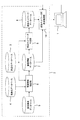
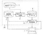
- FIG. 1 is a schematic diagram showing the overall configuration of the design support system in the present embodiment.
- the design support system includes a design work computer (input / output device) 1 and a design support device 2 connected to the computer 1.
- the computer 1 includes an input unit (in detail, a keyboard and a mouse) for a designer to input data, and a screen display unit (in detail, a display) for displaying processing results.
- design documents such as product design materials and specifications can be created using a document creation tool
- 3D shape data of all or part of the product can be created using 3D CAD.
- data such as design documents and three-dimensional shape data is stored in a database (not shown), and necessary data can be read from the database and displayed on the screen display unit.
- the design support apparatus 2 includes a part name database 3 for storing names of parts constituting the product, a phenomenon name database 4 for storing phenomenon names of defects that may occur in the product parts, and each past accident case that has occurred in the product.
- Accident case database 5 for storing the accident case documents (see FIG. 2 described later) created in the above, and information (details will be described later) are extracted for each accident case document stored in the accident case database 5, and the information is extracted.
- the related information extraction unit 6 that generates data associated with each accident case
- the related information database 7 that stores the data generated by the related information extraction unit 6, the part name database 3, and the related information database 7
- the component network generation unit 8 that generates component network data based on the data
- the component network generation unit A component network database 9 for storing data, a component network diagram display control unit 10 for displaying a component network diagram on the screen display unit of the computer 1 in accordance with a command from the computer 1 and controlling display of the component network diagram, It has.
- the accident case database 5 stores an accident case document 11 in which the title, the content of the accident, the degree of influence, and the countermeasures are described for each past accident case that has occurred in the product. More specifically, as shown in FIG. 2, for example, the accident case document 11 is provided with a title column 11a, an impact level column 11b, an accident content column 11c, and a countermeasure column 11d.
- the title column 11a describes the title
- the impact level column 11b indicates the impact level (specifically, the damage scale of the accident, for example, expressed in 5 stages from 1 to 5, with 5 being the most severe damage scale) Large).
- the accident content column 11c includes the accident content (specifically, the name of the primary part in which the malfunction occurred, the name of the phenomenon of the malfunction, and the secondary that is estimated to have affected or affected the malfunction of the primary part. A sentence including the name of the component) is described, and a countermeasure column 11d describes a countermeasure for the defect.
- FIG. 3 is a flowchart showing the processing contents of the related information extraction unit 6.
- step 120 the sentence in the accident content column 11c of the first accident case document 11 is morphologically analyzed and broken down into words.
- Morphological analysis is a process of decomposing sentences written in a natural language into words and discriminating parts of speech. Then, only nouns are extracted from the decomposed words. More specifically, for example, from the accident content column 11c of the accident example document 11 shown in FIG. 2, the nouns “fan”, “noise”, “measure”, “power”, “electric frequency”, “pump”, “Insufficient output”, “defect”, and “occurrence” are extracted. Then, the process proceeds to step 130, and the extracted all nouns and dimension to create a document vector F 1 which is as a component the number of occurrences of each noun. This document vector is for use in relevance calculation processing (see FIG. 10) described later.
- step 140 determines whether or not all nouns extracted from the accident content column 11c of the first accident case document 11 match the data stored in the phenomenon name database 4 sequentially. If they match, it is extracted as a defect phenomenon name.
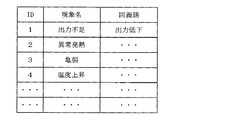
- the phenomenon name database 4 stores “insufficient output”, “insufficient strength”, “crack”, “temperature rise”, and the like as phenomenon names as shown in FIG.
- IDs and synonyms are stored corresponding to each phenomenon name.
- the ID is a value that identifies the phenomenon name and does not overlap with the others.
- a synonym “output reduction” or the like is stored for a phenomenon name “insufficient output”.
- the process proceeds to step 150, and among the nouns extracted from the accident content column 11c of the first accident case document 11, the nouns related to the nouns extracted as the trouble phenomenon names are stored in the part name database 3.
- the data is sequentially checked to determine whether or not they match, and if they match, it is extracted as the name of the primary part in which the failure occurred.
- the part name database 3 stores “fan”, “power supply”, “pump”, “electric heater”, and the like as part names as shown in FIG.
- an ID and a synonym corresponding to each part name are stored.
- the ID is a value that identifies a part name and does not overlap with others.
- a synonym “blower” or the like is stored for a part name “fan”. Then, for example, among all the nouns extracted from the accident content column 11c of the accident example document 11 shown in FIG. 2, the noun “pump” related to the noun “insufficient output” extracted as the phenomenon name of the malfunction is stored in the part name database. When the part name and synonym stored in 3 are sequentially checked, the part name “pump” stored in the part name database 3 matches, and this is extracted as the name of the primary part.
- step 160 determines whether or not the remaining nouns extracted from the accident content column 11c of the first accident case document 11 match the data stored in the part name database 3 sequentially. If they match, it is extracted as the name of the secondary part that is estimated to have affected or affected the failure of the primary part. Specifically, for example, the remaining nouns extracted from the accident content column 11c of the accident case document 11 shown in FIG.
- step 170 associated with the first of accidents document 11 are extracted from the title, the primary part of the name, failure of the phenomenon name, the secondary part of the name, degree of influence, failure of the measures, and the document vector F 1
- One record is stored in the related information database 7.
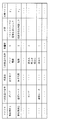
- the title “accident case 1”, the primary part name “pump”, the phenomenon name “output reduction”, the secondary part name “fan” ”And“ power source ”, the influence degree“ 5 ”, the countermeasure“ the power source of the fan and the pump are separated ”, and the document vector F 1 are associated with each other and stored in the related information database 7 (see FIG. 6).
- FIG. 6 one record is shown by one line.
- step 120 the sentence in the accident content column 11c of the second accident sentence example document 11 is decomposed into words by morphological analysis, and only nouns are extracted from the decomposed words.
- step 130 the extracted all nouns and dimension to create a document vector F 2 which was the number of occurrences of each noun components.
- step 140 all nouns are sequentially compared with the data stored in the phenomenon name database 4 to determine whether or not they match.
- step 150 determines whether or not the noun related to the noun extracted as the defect phenomenon name is matched with the data stored in the part name database 3 sequentially. Extracted as the name of the primary part. Thereafter, the process proceeds to step 160, where the remaining nouns are sequentially compared with the data stored in the part name database 3 to determine whether or not they match. If they match, the names are extracted as secondary part names. Then, the process proceeds to step 170, associated with the second of accidents document 11 are extracted from the title, the primary part of the name, failure of the phenomenon name, the secondary part of the name, degree of influence, failure of the measures, and the document vector F 2 One record is stored in the related information database 7.
- the title “Accident Case 2”, the name of the primary part “Electric heater”, the phenomenon name “Abnormal heat generation”, the name of the secondary part “Power”, the influence degree “3”, the countermeasure “Connection method” ”And the sentence vector F 2 are associated with each other and stored in the related information database 7 (see FIG. 6).
- the determination in step 180 is satisfied and the process is terminated. Even when the accident case document 11 is added to the accident case database 5, the steps 110 to 170 described above are repeated.
- FIG. 7 is a flowchart showing the processing contents of the component network generation unit 8.
- the part network data is matrix data indicating the relevance of parts as shown in FIG.
- step 220 Determine whether there is a record containing the th part name. For example, if there is a record including the second part name, the determination in step 220 is satisfied, and the process proceeds to step 230 to extract another part name included in the record. Thereafter, the process proceeds to step 240, where it is reflected in the part network data and stored in the part network database 9.
- the second component name “power” in the data of the component database 3 shown in FIG. 5 is searched as a keyword, two records are found from the data of the related information database shown in FIG.
- One record includes the component names “fan” and “pump” in addition to the component name “power”, but the relevance of this record is already reflected in the component network data.
- the other record includes a part name “electric heater” in addition to “power supply”. Therefore, as shown in FIG. 8, “1” is input at a location where the row in which the component name “power supply” is written and the column in which the component name “electric heater” is written, and the component name “electric heater” is entered. “1” is input at a location where the row in which “” is written intersects with the column in which the part name “power supply” is written.
- step 220 Determine whether there is a record containing the th part name. For example, if there is a record including the third part name, the determination in step 220 is satisfied and the process proceeds to step 230 to extract another part name included in the record. Thereafter, the process proceeds to step 240, where it is reflected in the part network data and stored in the part network database 9.
- the third part name “pump” in the data of the parts database 3 shown in FIG. 5 is searched as a keyword, two records are found from the data of the related information database shown in FIG.
- One record includes the part name “fan” and “power supply” in addition to the part name “pump”, but the relevance of this record is already reflected in the part network data.
- the other record includes part names “part A”, “part B”, and “part C” in addition to “pump”. Therefore, as shown in FIG. 8, a line where the part name “pump” is written and a column where the part names “part A”, “part B”, and “part C” are respectively written intersect with each other.
- step 220 Determine whether there is a record containing the th part name. For example, if there is a record including the fourth part name, the determination in step 220 is satisfied and the process proceeds to step 230 to extract another part name included in the record. Thereafter, the process proceeds to step 240, where it is reflected in the part network data and stored in the part network database 9.
- step 260 is satisfied, and the process ends. Even when a record is added to the related information database 7 (in other words, when an accident case document 11 is added to the accident case database 5), the steps 200 to 260 described above are repeated. It has become.
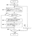
- FIG. 9 is a flowchart showing the processing contents of the component network diagram display control unit 10.
- FIG. 10 is a flowchart showing details of the calculation processing (step 360) of the importance level of related parts.
- step 300 data stored in the part network database 9 is read in accordance with a command from the computer 1, and a part network diagram based on the data is displayed on the screen display unit of the computer 1.
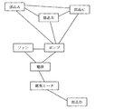
- Part network diagram display control means A specific example of the component network diagram is shown in FIG. In FIG. 11, based on the data of the part network database 9 shown in FIG. 6, the names of the parts constituting the product “fan”, “power supply”, “pump”, “electric heater”, “part A”, “parts” “B”, “Part C”, and “Part D” are displayed, and a line indicating their relevance is displayed.
- the name of the design change part is described in the design document (in other words, the design document displayed on the screen display unit of the computer 1) that the designer is referencing (or creating).
- the name of the design change part is extracted and selected from the description of the design document. Therefore, first, the process proceeds to step 310, where the text in the design document being referred to by the designer is morphologically analyzed and broken down into words, and only nouns are extracted from the broken down words. Thereafter, the process proceeds to step 320, where a document vector D is created with all extracted nouns as dimensions and the number of appearances of each noun as a component. This document vector is for use in relevance calculation processing described later.
- step 330 all nouns extracted from the design document are sequentially compared with the data stored in the part name database 3 to determine whether or not they match.
- Extract as name selection means. More specifically, for example, when all the nouns extracted from the design document 12 shown in FIG. 12 are sequentially compared with the part names and synonyms stored in the part name database 3, the parts stored in the part name database 3 will be described. The names “fan” and “power source” match, and these are extracted as the names of the design change parts.
- step 340 the name of the design change part on the part network diagram is highlighted (second related information display control means). Specifically, for example, as shown in FIG. 13, the outer frames of the names “fan” and “power supply” of the design-changed parts on the part network diagram are highlighted with double lines. Alternatively, for example, the color and shape of the outer frame may be changed and highlighted.
- step 350 related parts related to the design change part are acquired based on the data stored in the part network database 9, and the process proceeds to step 360 to calculate the importance for each related part (importance calculation means) ).
- importance calculation means for example, when “fan” and “power supply” are extracted as design change parts as described above, “pump” and “electric heater” are related parts related to “fan” and “power supply”, respectively. ”And calculate the importance of each.
- step 361 the name of the related part is determined as either one of the name of the primary part or the name of the secondary part from the data stored in the related information database 7.
- the included accident cases are searched, and the total sum a of the degree of influence of the accident cases is calculated.
- step 362 the total number b of components related to the related components is calculated based on the data stored in the component network database 9.
- the process proceeds to step 363, and the text associated with the accident case in which the name of the related part is included as either the name of the primary part or the name of the secondary part from the data stored in the related information database 7 Read vector F.
- step 364 the process proceeds to step 364, and the document vector F read in step 363 described above (specifically, the document vector in the accident content column 11c of the accident example document 11) and the text of the design document 12 created in step 320 described above.
- the similarity c between the accident case document 11 and the design document 12 is calculated (see Equation 1 below).
- Equation 1 the similarity c with the design document 12 is calculated for each accident case document, and an average c ′ thereof is calculated.
- step 365 where the sum of influences a calculated in step 361 described above, the number of parts b calculated in step 362 described above, and the similarity c calculated in step 364 described above (or similarity) To calculate the importance.
- the case of calculating the importance of the related component “pump” will be described.
- the importance may be calculated by weighting each of the above-described values a, b, c (or c ′). Also, the importance may be calculated using the number of parts b ′ obtained by subtracting the number of design-changed parts from the total number b instead of the total number b of the parts related to the related parts.
- step 370 the names of related parts on the component network diagram are highlighted step by step according to the importance calculated in step 360 described above.
- (Second related information display control means) Specifically, as shown in FIG. 13, for example, the outer frames of the names “pump” and “electric heater” of the related parts on the part network diagram are changed to five-level thickness according to the importance and are highlighted. To do.
- the outer frame of “pump” since the importance of “pump”> importance of “electric heater”, the outer frame of “pump” is thicker than the outer frame of “electric heater”.
- the outer frame of the name of the related part may be highlighted with five colors according to the importance, or may be highlighted with a five-stage shape. For example, the importance (numerical value) may be displayed near the name of the related part.
- the part network diagram display control unit 10 also has other display functions. For example, when the designer operates the input unit of the computer 1 and moves the cursor over the name of the component in the component network diagram displayed on the screen display unit of the computer 1, the component network diagram display control unit 10 Accident cases including the name of the primary part are retrieved from the data stored in the related information database 7, and the phenomenon name and countermeasure of the malfunction in the accident case are read. As shown in FIG. 14, the read phenomenon name and countermeasure are displayed on the component network diagram (first related information display control means).
- the design support apparatus 2 affects, in detail, the primary part in which a failure has occurred and the failure of the primary part based on past accident cases of the product.
- the data of the part network is generated on the basis of the relevance with the secondary part estimated to have been affected or affected.
- a component network diagram based on the data is displayed on the screen display unit of the computer 1.
- the design support apparatus 2 displays the name of a phenomenon that has occurred in a part and the countermeasure when the cursor moves over the part name in the part network diagram. Thereby, the designer can grasp
- the design support apparatus 2 highlights the name of the design-changed part on the part network diagram, and the name of the related part related to the design-changed part is stepwise according to the importance. Highlighted. Thereby, the designer can grasp the priority order of related parts to be examined without depending on the ability and experience of the designer.
- the part network diagram display control unit 10 stores the names of parts described in the design document displayed on the screen display unit of the computer 1 in the part name database 3.
- the part network diagram display control unit 10 changes the part to a design-changed part when the cursor is moved on the name of the part in the part network diagram, for example, by an operation of the input unit of the computer 1.
- the part network diagram display control unit 10 highlights the name of the design change part on the part network diagram and calculates the importance of the related part related to the design change part.
- the related component on the component network diagram has the function of highlighting the related component in stages according to the importance has been described as an example, but such a function may not be provided.
- the related information extraction unit 6 may not extract the degree of influence from the accident case document 11 and may not create the text vector F. That is, the data stored in the related information database 7 may not include the influence degree and the sentence vector F.
- the component network diagram display control unit 10 has been described by taking as an example the case where it has a function of displaying the phenomenon name and countermeasure of the failure on the component network diagram. It is not necessary to have it.
- the related information extraction unit 6 may not extract measures from the accident case document 11, and the data stored in the related information database 7 may not include the phenomenon name or measures.
- the configuration of the design support apparatus 2 including the phenomenon name database 4, the accident case database 5, and the related information extraction unit 6 has been described as an example. It is good also as a structure of 2 A of design support apparatuses which do not include the phenomenon name database 4, the accident example database 5, and the related information extraction part 6 like the modification shown by 15.
- it is data based on past accident cases of the product, and is associated with each accident case, and at least the name of the primary part in which the failure occurred, and whether or not the failure of the primary part was affected.
- Data including the name of the secondary part estimated to have been received may be generated by the computer 1 or the like and stored in the related information database 7.
- the component network diagram display control unit 10 has been described by way of example of displaying a component network diagram on the screen display unit of the computer 1, but the present invention is not limited to this. That is, for example, the design support apparatus 2 includes a screen display unit (specifically, a display) different from the screen display unit of the computer 1, and the component network diagram is displayed on the screen display unit of the design support apparatus 2. Good. Even in such a modification, the same effect as described above can be obtained.
- a second embodiment of the present invention will be described with reference to FIGS.
- a design change part is selected and highlighted on a CAD diagram displayed on a screen display unit of a computer, and related parts related to the design change part are highlighted according to importance. It is.
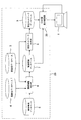
- FIG. 16 is a schematic diagram showing the overall configuration of the design support system in the present embodiment.
- the same parts as those in the first embodiment are denoted by the same reference numerals, and description thereof will be omitted as appropriate.
- the design support apparatus 2B like the design support apparatus 2 of the first embodiment, includes a part name database 3, a phenomenon name database 4, an accident case database 5, a related information extraction unit 6, A related information database 7, a component network generation unit 8, and a component network database 9 are provided.
- the design support apparatus 2B includes a CAD diagram display control unit 20 that performs display control of the CAD diagram.
- the CAD diagram display control unit 20 may be linked to a three-dimensional CAD for creating three-dimensional shape data on the computer 1, or may not be linked to a three-dimensional CAD and It is also possible to simply read the necessary CAD data from the database in accordance with the command and display it on the screen display unit of the computer 1.
- the CAD diagram display control unit 20 moves the cursor onto a part of the CAD diagram displayed on the screen display unit of the computer 1 by an operation of the input unit of the computer 1, for example,
- the part is selected as a design change part (selection means), and the part is highlighted (third related information display control means).
- the display color of the design change part “component E” on the CAD diagram is a predetermined first color (specifically, a color different from the normal display color). To highlight it.
- the CAD diagram display control unit 20 acquires related parts related to the design change parts based on the data stored in the part network database 9, and calculates the importance for each related part (importance calculating means). Specifically, first, from the data stored in the related information database 7, an accident case in which the name of the related part is included as one of the name of the primary part and the name of the secondary part is searched. Calculate the sum a of the impacts of accident cases. Based on the data stored in the parts network database 9, the total number b of parts related to the related parts is calculated. Then, the degree of importance is calculated by integrating the sum of influences a and the number of parts b.
- the importance may be calculated by weighting the above-described values a and b. Also, the importance may be calculated using the number of parts b ′ obtained by subtracting the number of design-changed parts from the total number b instead of the total number b of the parts related to the related parts.
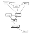
- the CAD diagram display control unit 20 highlights the related parts on the CAD diagram in stages according to the importance (third related information display control means). Specifically, as shown in FIG. 17, for example, the related components “component F” and “component G” are colored in five levels according to the importance (in detail, the normal display color and the first color described above are used). The color is different from the color, and is changed to the second to sixth colors (predetermined according to the level of importance) and highlighted. For example, the importance (numerical value) may be displayed near the related part.
- the CAD diagram display control unit 20 has other display functions in addition to the display function described above. For example, when the designer operates the input unit of the computer 1 and moves the cursor onto a part of the CAD diagram displayed on the screen display unit of the computer 1, the CAD diagram display control unit 20 indicates that the name of the component is primary. Accident cases included as part names are searched from the data stored in the related information database 7, and the phenomenon names and countermeasures of defects in the accident cases are read. Then, as shown in FIG. 17, the read phenomenon name and countermeasure are displayed on the CAD diagram (fourth related information display control means).
- the CAD diagram display control unit 20 has been described by taking an example in which the CAD diagram display control unit 20 has a function of displaying the phenomenon name and countermeasure of the failure on the CAD diagram.
- the CAD diagram display control unit 20 has such a function.
- the related information extraction unit 6 may not extract measures from the accident case document 11, and the data stored in the related information database 7 may not include the phenomenon name or measures.
- the configuration of the design support apparatus 2B including the phenomenon name database 4, the accident case database 5, and the related information extraction unit 6 has been described as an example.
- the present invention is not limited to this.
- FIG. 1 it is data based on past accident cases of the product, and is associated with each accident case, and at least the name of the primary part in which the failure occurred, and whether or not the failure of the primary part was affected.
- Data including the name of the secondary part estimated to have been received may be generated by the computer 1 or the like and stored in the related information database 7.
Landscapes
- Engineering & Computer Science (AREA)
- Theoretical Computer Science (AREA)
- Physics & Mathematics (AREA)
- General Engineering & Computer Science (AREA)
- General Physics & Mathematics (AREA)
- Evolutionary Computation (AREA)
- Geometry (AREA)
- Computer Hardware Design (AREA)
- Quality & Reliability (AREA)
- Management, Administration, Business Operations System, And Electronic Commerce (AREA)
- Information Retrieval, Db Structures And Fs Structures Therefor (AREA)
- Architecture (AREA)
- Software Systems (AREA)
Abstract
Description

そして、ステップ365に進み、前述のステップ361で演算された影響度の総和aと、前述のステップ362で演算された部品数bと、前述のステップ364で演算された類似度c(又は類似度の平均c’)とを積算して重要度を演算する。
なお、CAD図表示制御部20は、コンピュータ1上で3次元形状データを作成する3次元CADと連携するものであってもよいし、あるいは、3次元CADとは連携せず、コンピュータ1からの指令に応じてデータベースから必要なCADデータを読込んでコンピュータ1の画面表示部に表示させるだけのものであってもよい。
3 部品名データベース
4 現象名データベース
5 事故事例データベース
6 関連情報抽出部(関連情報抽出手段)
7 関連情報データベース
8 部品ネットワーク生成部(部品ネットワーク生成手段)
9 部品ネットワークデータベースと、
10 部品ネットワーク図表示制御部(部品ネットワーク図表示制御手段、第1の関連情報表示制御手段、選択手段、重要度演算手段、第2の関連情報表示制御手段)
11 事故事例ドキュメント
12 設計ドキュメント
20 CAD図表示制御部(選択手段、重要度演算手段、第3の関連情報表示制御手段、第4の関連情報表示制御手段)
Claims (12)
- 既存の製品の部品を設計変更する場合にその影響を受ける他の部品を提示する設計支援システムにおいて、
製品を構成する部品の名称を格納する部品名データベースと、
製品の過去の事故事例に基づいて生成されたデータであって、事故事例毎に関連付けられ、少なくとも、不具合が生じた一次部品の名称、及びその一次部品の不具合に影響を与えたか若しくは影響を受けたと推定された二次部品の名称を含むデータを格納する関連情報データベースと、
前記部品名データベース及び前記関連情報データベースに格納されたデータに基づき、製品を構成する部品の名称とともにそれら部品の関連性を網羅した部品ネットワークのデータを生成する部品ネットワーク生成手段と、
前記部品ネットワーク生成手段で生成されたデータを格納する部品ネットワークデータベースと、
前記部品ネットワークデータベースに格納されたデータを読込み、そのデータによる部品ネットワーク図を画面表示部に表示させる部品ネットワーク図表示制御手段とを備えたことを特徴とする設計支援システム。 - 請求項1記載の設計支援システムにおいて、
製品の部品に起こりうる不具合の現象名を格納する現象名データベースと、
製品に起きた過去の事故事例毎に、不具合が生じた一次部品の名称、その不具合の現象名、一次部品の不具合に影響を与えたか若しくは影響を受けたと推定された二次部品の名称、事故の被害規模である影響度、及び不具合の対策が記載された事故事例ドキュメントを格納する事故事例データベースと、
前記事故事例データベースに格納された事故事例ドキュメント毎に、前記現象名データベースに格納されたデータと照合して不具合の現象名を抽出するとともに、前記部品名データベースに格納されたデータと照合して一次部品の名称及び二次部品の名称を抽出し、さらに影響度及び不具合の対策を抽出し、それら不具合の現象名、一次部品の名称、二次部品の名称、影響度、及び不具合の対策を事故事例毎に関連付けたデータを生成する関連情報抽出手段とを備え、
前記関連情報データベースは、前記関連情報抽出手段で生成されたデータを格納することを特徴とする設計支援システム。 - 請求項2記載の設計支援システムにおいて、
前記部品ネットワーク図上で表示された部品の名称のうちのいずれか一つが選択された場合に、その選択された部品の名称が一次部品の名称として含まれた事故事例を前記関連情報データベースに格納されたデータから検索し、その事故事例における不具合の現象名及び対策を、前記部品ネットワーク図上で表示させる第1の関連情報表示制御手段を備えたことを特徴とする設計支援システム。 - 請求項2又は3記載の設計支援システムにおいて、
設計変更部品を選択する選択手段と、
前記選択手段で選択された設計変更部品に関連する関連部品を、前記部品ネットワークデータベースに格納されたデータに基づいて取得し、前記関連部品毎に重要度を演算する重要度演算手段と、
前記部品ネットワーク図上、前記選択手段で選択された設計変更部品の名称を強調表示させ、その設計変更部品に関連する前記関連部品の名称を前記重要度演算手段で演算された重要度に応じて段階的に強調表示させる第2の関連情報表示制御手段とを備えたことを特徴とする設計支援システム。 - 請求項4記載の設計支援システムにおいて、
前記選択手段は、前記画面表示部に表示中の設計ドキュメントに記載された部品の名称を、前記部品名データベースに格納されたデータと照合して抽出し、これを設計変更部品として選択することを特徴とする設計支援システム。 - 請求項5記載の設計支援システムにおいて、
前記重要度演算手段は、
前記関連部品毎に、
前記関連情報データベースに格納されたデータから、前記関連部品の名称が一次部品の名称及び二次部品の名称のうちのいずれか一方として含まれた事故事例を検索し、その事故事例の影響度の総和aを演算し、
前記部品ネットワークデータベースに格納されたデータに基づき、前記関連部品に関連する部品の総数bを演算し、
前記関連部品の名称が一次部品の名称及び二次部品の名称のうちのいずれか一方として含まれた事故事例ドキュメントの文章ベクトルと、前記画面表示部に表示中の設計ドキュメントの文章ベクトルとを用いて、事故事例ドキュメントと設計ドキュメントとの類似度cを演算し、事故事例ドキュメントが複数あって複数の類似度cが得られる場合には類似度の平均c’を演算し、
影響度の総和a、部品数b、及び類似度c若しくは類似度の平均c’を積算して重要度を演算することを特徴とする設計支援システム。 - 請求項4記載の設計支援システムにおいて、
前記選択手段は、前記部品ネットワーク図上で設計変更部品を選択することを特徴とする設計支援システム。 - 請求項7記載の設計支援システムにおいて、
前記重要度演算手段は、
前記関連部品毎に、
前記関連情報データベースに格納されたデータから前記関連部品の名称が一次部品の名称及び二次部品の名称のうちのいずれか一方として含まれた事故事例を検索し、その事故事例の影響度の総和aを演算し、
前記部品ネットワークデータベースに格納されたデータに基づき、前記関連部品に関連する部品の総数bを演算し、
影響度の総和a及び部品数bを積算して重要度を演算することを特徴とする設計支援システム。 - 既存の製品の部品を設計変更する場合にその影響を受ける他の部品を提示する設計支援システムにおいて、
製品を構成する部品の名称を格納する部品名データベースと、
製品の過去の事故事例に基づいて生成されたデータであって、事故事例毎に関連付けられ、少なくとも、不具合が生じた一次部品の名称、その一次部品の不具合に影響を与えたか若しくは影響を受けたと推定された二次部品の名称、及び事故の被害規模である影響度を含むデータを格納する関連情報データベースと、
前記部品名データベース及び前記関連情報データベースに格納されたデータに基づき、製品を構成する部品の名称とともにそれら部品の関連性を網羅した部品ネットワークのデータを生成する部品ネットワーク生成手段と、
前記部品ネットワーク生成手段で生成されたデータを格納する部品ネットワークデータベースと、
画面表示部に表示されたCAD図上で設計変更部品を選択する選択手段と、
前記選択手段で選択された設計変更部品に関連する関連部品を、前記部品ネットワークデータベースに格納されたデータに基づいて取得し、前記関連部品毎に重要度を演算する重要度演算手段と、
前記CAD図上、前記選択手段で選択された設計変更部品を強調表示させ、その設計変更部品に関連する前記関連部品を前記重要度演算手段で演算された重要度に応じて段階的に強調表示させる第3の関連情報表示制御手段とを備えたことを特徴とする設計支援システム。 - 請求項9記載の設計支援システムにおいて、
製品の部品に起こりうる不具合の現象名を格納する現象名データベースと、
製品に起きた過去の事故事例毎に、不具合が生じた一次部品の名称、その不具合の現象名、一次部品の不具合に影響を与えたか若しくは影響を受けたと推定された二次部品の名称、事故の被害規模である影響度、及び不具合の対策が記載された事故事例ドキュメントを格納する事故事例データベースと、
前記事故事例データベースに格納された事故事例ドキュメント毎に、前記現象名データベースに格納されたデータと照合して不具合の現象名を抽出するとともに、前記部品名データベースに格納されたデータと照合して一次部品の名称及び二次部品の名称を抽出し、さらに影響度及び不具合の対策を抽出し、それら不具合の現象名、一次部品の名称、二次部品の名称、影響度、及び不具合の対策を事故事例毎に関連付けたデータを生成する関連情報抽出手段とを備え、
前記関連情報データベースは、前記関連情報抽出手段で生成されたデータを格納することを特徴とする設計支援システム。 - 請求項10記載の設計支援システムにおいて、
前記CAD図上で表示された設計変更部品の名称及び関連部品の名称のうちのいずれか一方が選択された場合に、その選択された部品の名称が一次部品の名称として含まれた事故事例を前記関連情報データベースに格納されたデータから検索し、その事故事例における不具合の現象名及び対策を、前記CAD図上で表示させる第4の関連情報表示制御手段を備えたことを特徴とする設計支援システム。 - 請求項9~11のいずれか1項記載の設計支援システムにおいて、
前記重要度演算手段は、
前記関連部品毎に、
前記関連情報データベースに格納されたデータから前記関連部品の名称が一次部品の名称及び二次部品の名称のうちのいずれか一方として含まれた事故事例を検索し、その事故事例の影響度の総和aを演算し、
前記部品ネットワークデータベースに格納されたデータに基づき、前記関連部品に関連する部品の総数bを演算し、
影響度の総和a及び部品数bを積算して重要度を演算することを特徴とする設計支援システム。
Priority Applications (3)
| Application Number | Priority Date | Filing Date | Title |
|---|---|---|---|
| US13/993,565 US9146827B2 (en) | 2010-12-13 | 2010-12-13 | Support system |
| PCT/JP2010/072414 WO2012081080A1 (ja) | 2010-12-13 | 2010-12-13 | 設計支援システム |
| JP2012548561A JP5602247B2 (ja) | 2010-12-13 | 2010-12-13 | 設計支援システム |
Applications Claiming Priority (1)
| Application Number | Priority Date | Filing Date | Title |
|---|---|---|---|
| PCT/JP2010/072414 WO2012081080A1 (ja) | 2010-12-13 | 2010-12-13 | 設計支援システム |
Publications (1)
| Publication Number | Publication Date |
|---|---|
| WO2012081080A1 true WO2012081080A1 (ja) | 2012-06-21 |
Family
ID=46244209
Family Applications (1)
| Application Number | Title | Priority Date | Filing Date |
|---|---|---|---|
| PCT/JP2010/072414 WO2012081080A1 (ja) | 2010-12-13 | 2010-12-13 | 設計支援システム |
Country Status (3)
| Country | Link |
|---|---|
| US (1) | US9146827B2 (ja) |
| JP (1) | JP5602247B2 (ja) |
| WO (1) | WO2012081080A1 (ja) |
Cited By (10)
| Publication number | Priority date | Publication date | Assignee | Title |
|---|---|---|---|---|
| US20150149553A1 (en) * | 2013-11-28 | 2015-05-28 | International Business Machines Corporation | Apparatus and method for processing information and program for the same |
| JP2016095723A (ja) * | 2014-11-14 | 2016-05-26 | 富士通株式会社 | 対応情報生成プログラム、対応情報生成装置及び対応情報生成方法 |
| WO2016167057A1 (ja) * | 2015-04-16 | 2016-10-20 | 株式会社日立製作所 | 不具合情報活用支援装置及び不具合情報活用支援方法 |
| CN108427542A (zh) * | 2017-02-14 | 2018-08-21 | 富士施乐株式会社 | 设计支持系统和设计支持方法 |
| JP2019095978A (ja) * | 2017-11-21 | 2019-06-20 | 富士ゼロックス株式会社 | 設計支援システム、設計支援装置、及び、設計支援プログラム |
| JP2019121210A (ja) * | 2018-01-09 | 2019-07-22 | 鹿島建設株式会社 | 安全情報提供システム |
| JP2020119128A (ja) * | 2019-01-22 | 2020-08-06 | 株式会社三菱総合研究所 | 情報処理装置、情報処理方法及びプログラム |
| JP2020154897A (ja) * | 2019-03-20 | 2020-09-24 | 株式会社日立ビルシステム | 不具合情報抽出装置及び方法並びにプログラム |
| JP2020160869A (ja) * | 2019-03-27 | 2020-10-01 | 三菱ロジスネクスト株式会社 | 作業機械に対するサービスに係る文書作成システム |
| US10943033B2 (en) | 2017-09-20 | 2021-03-09 | Kabushiki Kaisha Toshiba | Information retrieval apparatus, information retrieval method, and computer program product |
Families Citing this family (4)
| Publication number | Priority date | Publication date | Assignee | Title |
|---|---|---|---|---|
| US10078619B2 (en) * | 2014-12-16 | 2018-09-18 | International Business Machines Corporation | Dynamic association of application workload tiers to infrastructure elements in a cloud computing environment |
| WO2016117103A1 (ja) * | 2015-01-23 | 2016-07-28 | 株式会社 日立ハイテクノロジーズ | 半導体測定装置、或いは半導体検査装置に用いられるレシピ作成装置 |
| JP6705845B2 (ja) * | 2018-02-08 | 2020-06-03 | ファナック株式会社 | 障害部位特定装置、障害部位特定方法及び障害部位特定プログラム |
| US11886776B2 (en) * | 2018-05-08 | 2024-01-30 | Autodesk, Inc. | Techniques for generating graph-based representations of complex mechanical assemblies |
Citations (4)
| Publication number | Priority date | Publication date | Assignee | Title |
|---|---|---|---|---|
| JP2005107773A (ja) * | 2003-09-30 | 2005-04-21 | Hitachi Ltd | 不良影響度評価方法および設計支援システム |
| JP2008084242A (ja) * | 2006-09-29 | 2008-04-10 | Omron Corp | データベース作成装置およびデータベース活用支援装置 |
| JP2008102758A (ja) * | 2006-10-19 | 2008-05-01 | Omron Corp | Fmeaシートの作成方法およびfmeaシート自動作成装置 |
| JP2008209988A (ja) * | 2007-02-23 | 2008-09-11 | Omron Corp | Fmeaシート作成装置 |
Family Cites Families (7)
| Publication number | Priority date | Publication date | Assignee | Title |
|---|---|---|---|---|
| JP2000293552A (ja) * | 1999-04-01 | 2000-10-20 | Nec Corp | ハードウェア設計管理装置 |
| US6847916B1 (en) * | 2000-06-12 | 2005-01-25 | I/O Controls Corporation | Method and system for monitoring, controlling, and locating portable devices performing remote diagnostic analysis of control network |
| US6751661B1 (en) * | 2000-06-22 | 2004-06-15 | Applied Systems Intelligence, Inc. | Method and system for providing intelligent network management |
| JP2003162504A (ja) * | 2001-11-26 | 2003-06-06 | Hitachi Ltd | 障害分析支援システム |
| US7092771B2 (en) * | 2002-11-14 | 2006-08-15 | Rockwell Automation Technologies, Inc. | Industrial control and monitoring method and system |
| JP2007323219A (ja) | 2006-05-31 | 2007-12-13 | Hitachi Ltd | Fmea支援装置、その装置、そのプログラム及びその媒体 |
| US8612372B2 (en) * | 2008-08-29 | 2013-12-17 | International Business Machines Corporation | Detection rule-generating facility |
-
2010
- 2010-12-13 US US13/993,565 patent/US9146827B2/en not_active Expired - Fee Related
- 2010-12-13 JP JP2012548561A patent/JP5602247B2/ja not_active Expired - Fee Related
- 2010-12-13 WO PCT/JP2010/072414 patent/WO2012081080A1/ja active Application Filing
Patent Citations (4)
| Publication number | Priority date | Publication date | Assignee | Title |
|---|---|---|---|---|
| JP2005107773A (ja) * | 2003-09-30 | 2005-04-21 | Hitachi Ltd | 不良影響度評価方法および設計支援システム |
| JP2008084242A (ja) * | 2006-09-29 | 2008-04-10 | Omron Corp | データベース作成装置およびデータベース活用支援装置 |
| JP2008102758A (ja) * | 2006-10-19 | 2008-05-01 | Omron Corp | Fmeaシートの作成方法およびfmeaシート自動作成装置 |
| JP2008209988A (ja) * | 2007-02-23 | 2008-09-11 | Omron Corp | Fmeaシート作成装置 |
Cited By (21)
| Publication number | Priority date | Publication date | Assignee | Title |
|---|---|---|---|---|
| US10122811B2 (en) | 2013-11-28 | 2018-11-06 | International Business Machines Corporation | Method for determining identities between users |
| JP2015106178A (ja) * | 2013-11-28 | 2015-06-08 | インターナショナル・ビジネス・マシーンズ・コーポレーションInternational Business Machines Corporation | 情報処理装置、情報処理方法、及び、プログラム |
| US20170085660A1 (en) * | 2013-11-28 | 2017-03-23 | International Business Machines Corporation | Apparatus and method for processing information and program for the same |
| US9800678B2 (en) | 2013-11-28 | 2017-10-24 | International Business Machines Corporation | Apparatus and method for processing information and program for the same |
| US9819755B2 (en) | 2013-11-28 | 2017-11-14 | International Business Machines Corporation | Apparatus and method for processing information and program for the same |
| US20170366631A1 (en) * | 2013-11-28 | 2017-12-21 | International Business Machines Corporation | Apparatus and method for processing information and program for the same |
| US20170366632A1 (en) * | 2013-11-28 | 2017-12-21 | International Business Machines Corporation | Apparatus and method for processing information and program for the same |
| US10129350B2 (en) | 2013-11-28 | 2018-11-13 | International Business Machines Corporation | Apparatus for determining identities between users |
| US20150149553A1 (en) * | 2013-11-28 | 2015-05-28 | International Business Machines Corporation | Apparatus and method for processing information and program for the same |
| JP2016095723A (ja) * | 2014-11-14 | 2016-05-26 | 富士通株式会社 | 対応情報生成プログラム、対応情報生成装置及び対応情報生成方法 |
| WO2016167057A1 (ja) * | 2015-04-16 | 2016-10-20 | 株式会社日立製作所 | 不具合情報活用支援装置及び不具合情報活用支援方法 |
| JP2018132882A (ja) * | 2017-02-14 | 2018-08-23 | 富士ゼロックス株式会社 | 設計支援システムおよびプログラム |
| CN108427542A (zh) * | 2017-02-14 | 2018-08-21 | 富士施乐株式会社 | 设计支持系统和设计支持方法 |
| US10943033B2 (en) | 2017-09-20 | 2021-03-09 | Kabushiki Kaisha Toshiba | Information retrieval apparatus, information retrieval method, and computer program product |
| JP2019095978A (ja) * | 2017-11-21 | 2019-06-20 | 富士ゼロックス株式会社 | 設計支援システム、設計支援装置、及び、設計支援プログラム |
| JP7003596B2 (ja) | 2017-11-21 | 2022-02-04 | 富士フイルムビジネスイノベーション株式会社 | 設計支援システム、設計支援装置、及び、設計支援プログラム |
| JP2019121210A (ja) * | 2018-01-09 | 2019-07-22 | 鹿島建設株式会社 | 安全情報提供システム |
| JP2020119128A (ja) * | 2019-01-22 | 2020-08-06 | 株式会社三菱総合研究所 | 情報処理装置、情報処理方法及びプログラム |
| JP2020154897A (ja) * | 2019-03-20 | 2020-09-24 | 株式会社日立ビルシステム | 不具合情報抽出装置及び方法並びにプログラム |
| JP7164473B2 (ja) | 2019-03-20 | 2022-11-01 | 株式会社日立ビルシステム | 不具合情報抽出装置及び方法並びにプログラム |
| JP2020160869A (ja) * | 2019-03-27 | 2020-10-01 | 三菱ロジスネクスト株式会社 | 作業機械に対するサービスに係る文書作成システム |
Also Published As
| Publication number | Publication date |
|---|---|
| US20130339810A1 (en) | 2013-12-19 |
| US9146827B2 (en) | 2015-09-29 |
| JPWO2012081080A1 (ja) | 2014-05-22 |
| JP5602247B2 (ja) | 2014-10-08 |
Similar Documents
| Publication | Publication Date | Title |
|---|---|---|
| JP5602247B2 (ja) | 設計支援システム | |
| US11029814B1 (en) | Visualization of a machine learning confidence score and rationale | |
| US10073827B2 (en) | Method and system to generate a process flow diagram | |
| US8533140B2 (en) | Method and system for design check knowledge construction | |
| WO2010038540A1 (ja) | テキストセグメントを有する文書から用語を抽出するためのシステム | |
| JP5834883B2 (ja) | 因果関係要約方法、因果関係要約装置及び因果関係要約プログラム | |
| US20120150920A1 (en) | Method and system for linking textual concepts and physical concepts | |
| EP2362333A1 (en) | System for requirement identification and analysis based on capability model structure | |
| JP6542612B2 (ja) | テストシナリオ生成支援装置およびテストシナリオ生成支援方法 | |
| EP3667544B1 (en) | Designing a structural product | |
| US20080126920A1 (en) | Method for creating FMEA sheet and device for automatically creating FMEA sheet | |
| US20130159209A1 (en) | Product information | |
| US8996357B2 (en) | Method for generating diagrams, and information processing apparatus for same | |
| JP5334901B2 (ja) | チェックリスト自動生成装置、チェックリスト自動生成方法およびチェックリスト自動生成プログラム | |
| JP6135866B2 (ja) | 同表記異義語識別装置、方法及びプログラム | |
| JP7343348B2 (ja) | プログラミング支援装置及びプログラミング支援方法 | |
| WO2022054329A1 (ja) | 使用環境に基づく故障要因優先順位算出装置および方法 | |
| US20120310910A1 (en) | Method of Data Fusion and Providing Information in a Computer System | |
| JP5172308B2 (ja) | テキスト整形規則獲得装置、構造判定装置、それらのプログラム | |
| JP7531748B2 (ja) | 学習装置、管理シート作成支援装置、プログラム、学習方法及び管理シート作成支援方法 | |
| US20090299997A1 (en) | Grouping work support processing method and apparatus | |
| JP2009087009A (ja) | 文検索装置,文検索プログラム,文検索方法 | |
| JP5245481B2 (ja) | 評価手順生成方法,装置及びプログラム | |
| JP5455060B2 (ja) | データベース、類推エンジン及び類推システム | |
| English et al. | Striking a balance: Human and computer contributions to learning through semantic analysis |
Legal Events
| Date | Code | Title | Description |
|---|---|---|---|
| 121 | Ep: the epo has been informed by wipo that ep was designated in this application |
Ref document number: 10860876 Country of ref document: EP Kind code of ref document: A1 |
|
| ENP | Entry into the national phase |
Ref document number: 2012548561 Country of ref document: JP Kind code of ref document: A |
|
| NENP | Non-entry into the national phase |
Ref country code: DE |
|
| WWE | Wipo information: entry into national phase |
Ref document number: 13993565 Country of ref document: US |
|
| 122 | Ep: pct application non-entry in european phase |
Ref document number: 10860876 Country of ref document: EP Kind code of ref document: A1 |