WO2012077155A1 - 並列差動符号化回路 - Google Patents
並列差動符号化回路 Download PDFInfo
- Publication number
- WO2012077155A1 WO2012077155A1 PCT/JP2010/007085 JP2010007085W WO2012077155A1 WO 2012077155 A1 WO2012077155 A1 WO 2012077155A1 JP 2010007085 W JP2010007085 W JP 2010007085W WO 2012077155 A1 WO2012077155 A1 WO 2012077155A1
- Authority
- WO
- WIPO (PCT)
- Prior art keywords
- differential encoding
- parallel
- circuit
- encoding circuit
- output data
- Prior art date
Links
Images


Classifications
-
- H—ELECTRICITY
- H04—ELECTRIC COMMUNICATION TECHNIQUE
- H04L—TRANSMISSION OF DIGITAL INFORMATION, e.g. TELEGRAPHIC COMMUNICATION
- H04L27/00—Modulated-carrier systems
- H04L27/18—Phase-modulated carrier systems, i.e. using phase-shift keying
- H04L27/20—Modulator circuits; Transmitter circuits
- H04L27/2032—Modulator circuits; Transmitter circuits for discrete phase modulation, e.g. in which the phase of the carrier is modulated in a nominally instantaneous manner
- H04L27/2053—Modulator circuits; Transmitter circuits for discrete phase modulation, e.g. in which the phase of the carrier is modulated in a nominally instantaneous manner using more than one carrier, e.g. carriers with different phases
- H04L27/206—Modulator circuits; Transmitter circuits for discrete phase modulation, e.g. in which the phase of the carrier is modulated in a nominally instantaneous manner using more than one carrier, e.g. carriers with different phases using a pair of orthogonal carriers, e.g. quadrature carriers
- H04L27/2067—Modulator circuits; Transmitter circuits for discrete phase modulation, e.g. in which the phase of the carrier is modulated in a nominally instantaneous manner using more than one carrier, e.g. carriers with different phases using a pair of orthogonal carriers, e.g. quadrature carriers with more than two phase states
- H04L27/2071—Modulator circuits; Transmitter circuits for discrete phase modulation, e.g. in which the phase of the carrier is modulated in a nominally instantaneous manner using more than one carrier, e.g. carriers with different phases using a pair of orthogonal carriers, e.g. quadrature carriers with more than two phase states in which the data are represented by the carrier phase, e.g. systems with differential coding
-
- H—ELECTRICITY
- H03—ELECTRONIC CIRCUITRY
- H03M—CODING; DECODING; CODE CONVERSION IN GENERAL
- H03M7/00—Conversion of a code where information is represented by a given sequence or number of digits to a code where the same, similar or subset of information is represented by a different sequence or number of digits
-
- H—ELECTRICITY
- H04—ELECTRIC COMMUNICATION TECHNIQUE
- H04B—TRANSMISSION
- H04B10/00—Transmission systems employing electromagnetic waves other than radio-waves, e.g. infrared, visible or ultraviolet light, or employing corpuscular radiation, e.g. quantum communication
- H04B10/50—Transmitters
- H04B10/516—Details of coding or modulation
- H04B10/548—Phase or frequency modulation
- H04B10/556—Digital modulation, e.g. differential phase shift keying [DPSK] or frequency shift keying [FSK]
- H04B10/5561—Digital phase modulation
-
- H—ELECTRICITY
- H04—ELECTRIC COMMUNICATION TECHNIQUE
- H04L—TRANSMISSION OF DIGITAL INFORMATION, e.g. TELEGRAPHIC COMMUNICATION
- H04L25/00—Baseband systems
- H04L25/38—Synchronous or start-stop systems, e.g. for Baudot code
- H04L25/40—Transmitting circuits; Receiving circuits
- H04L25/49—Transmitting circuits; Receiving circuits using code conversion at the transmitter; using predistortion; using insertion of idle bits for obtaining a desired frequency spectrum; using three or more amplitude levels ; Baseband coding techniques specific to data transmission systems
-
- H—ELECTRICITY
- H04—ELECTRIC COMMUNICATION TECHNIQUE
- H04L—TRANSMISSION OF DIGITAL INFORMATION, e.g. TELEGRAPHIC COMMUNICATION
- H04L27/00—Modulated-carrier systems
- H04L27/18—Phase-modulated carrier systems, i.e. using phase-shift keying
- H04L27/20—Modulator circuits; Transmitter circuits
- H04L27/2096—Arrangements for directly or externally modulating an optical carrier
Definitions
- the present invention relates to a parallel differential encoding circuit used in a communication apparatus such as an optical fiber transmission apparatus and a radio transceiver.
- phase modulation techniques such as Differential Quadrature Phase Shift Keying (DQPSK) and digital coherent technologies such as Dual-Polarized Quadrature Phase Shift Keying (DP-QPSK) are methods for realizing ultra-high speed and large capacity signal transmission in optical communication systems.
- DQPSK Differential Quadrature Phase Shift Keying
- DP-QPSK Dual-Polarized Quadrature Phase Shift Keying
- Apol-DPSK Alternate ⁇ ⁇ ⁇ ⁇ Polarization Differential Phase Shift keying
- a detector using a delay interferometer that detects a phase difference between symbols before and after transmission is used as a receiver.
- the transmitter requires a circuit called a differential encoding circuit or precoder that assigns transmission data to a phase difference in advance.
- the phase of the received light is detected by the local light of the receiver, but the absolute phase on the transmission side is unknown and data cannot be restored.
- differential encoding that can restore data even when the initial phase is unknown may be used.
- the differential encoding process is realized by a high-speed digital circuit, but in order to calculate the phase difference, the optical signal phase information output immediately before must be held by the delay element. For this reason, a feedback path that operates at the symbol rate exists in the differential encoding circuit. In optical communication, since the bit rates are 40 Gbps and 100 Gbps, the feedback path is required to operate at several tens of GHz, and there is a problem that implementation becomes very difficult.
- Patent Document 1 discloses a circuit creation technique that reduces the operation speed of a digital circuit by enabling differential coding circuits to be developed in parallel and enables digital circuit mounting in a general LSI process. .
- the present invention has been made to solve such a problem, and an object thereof is to obtain a parallel differential encoding circuit suitable for a long-distance transmission format.
- a parallel differential encoding circuit is a parallel differential encoding circuit that generates parallel output data by differentially encoding parallel input data, and has n (2 ⁇ n, n is an integer) rows.
- a first differential encoding circuit that differentially encodes parallel input data and generates parallel output data of n (2 ⁇ n, n is an integer) rows; and n (2 ⁇ n, n is an integer) rows
- a second differential encoding circuit that differentially encodes parallel input data to generate parallel output data of n (2 ⁇ n, n is an integer) rows, and parallel output data of the first differential encoding circuit
- a multiplexing circuit for alternately multiplexing and outputting the parallel output data of the second differential encoding circuit.
- FIG. 1 is a configuration diagram showing a parallel differential encoding circuit according to the present embodiment.
- the parallel differential encoding circuit of this embodiment includes a first differential encoding circuit 1, a second differential encoding circuit 2, and a multiplexing circuit 3.
- the first differential encoding circuit 1 and the second differential encoding circuit 2 are DPSK differential encoding circuits, respectively.
- the first differential encoding circuit 1 calculates from two rows of parallel input data I1 and I2 and outputs two rows of parallel output data O1 and O2.
- the first differential encoding circuit 1 includes exclusive OR circuits 1a and 1b and a delay element 1c, and delays the parallel output data O2 from the exclusive OR circuit 1b by the delay element 1c.
- the logical OR circuit 1a has a feedback path for performing an exclusive OR operation with the parallel input data I1.
- the configuration of the second differential encoding circuit 2 is the same as that of the first differential encoding circuit 1, and is calculated from two rows of parallel input data I3 and I4, and two rows of parallel output data O3 and O4 are obtained. Output.
- the second differential encoding circuit 2 is also composed of exclusive OR circuits 2a and 2b and a delay element 2c, and delays the parallel output data O4 from the exclusive OR circuit 2b by the delay element 2c.
- the exclusive OR circuit 2a has a feedback path for performing an exclusive OR operation with the parallel input data I3.
- the multiplexing circuit 3 is a 4: 1 MUX that time-multiplexes four parallel output signals, and outputs the parallel output data O1, O3, O2, and O4 to the serial output SO in the order of four times the speed.
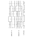
- FIG. 2 is a timing chart for explaining the relationship between transmission data and optical phase in a general DPSK system
- FIG. 3 is a timing chart for explaining the operation of the first embodiment.
- transmission data is assigned to a phase difference between transmission light phases modulated by a phase modulator.
- the data sequence after one-symbol differential encoding is “01001101101001111100” with respect to the transmission data sequence “01101011011101000010”.
- the phase modulator converts “0” to no phase “0” and “1” to phase “ ⁇ ”
- the transmitted optical phase sequence becomes “00 ⁇ 00 ⁇ 0 ⁇ 0 ⁇ 00 ⁇ 00”.
- the phase difference is detected by delay detection in the receiver, if the preceding and following symbols are “00” and “ ⁇ ”, the detected phase is “0”, and if “0 ⁇ ” and “ ⁇ 0”, the detected phase is “ ⁇ " Therefore, in the example of FIG. 2, the detection phase after delay detection is “0 ⁇ 0 ⁇ 0 ⁇ 0 ⁇ 0 ⁇ 0000 ⁇ 0”. When this is converted into an electrical signal and the data is restored, “01101011011101000010” equal to the original transmission data sequence is obtained.
- FIG. 4 shows a sequence when the multiplexed output shown in FIG. 3 is modulated by the phase modulator and the phase difference is detected by the 2-symbol delay detector.
- the original transmission data sequence can be restored by time-separating this and returning it to “1000”, “10100”, “1101”, and “00100”. Note that illustration of the phase modulator, the 2-symbol delay detector, and the time-division-separated configuration is omitted.
- differential encoding circuit corresponding to the DPSK method can be realized by a method other than the exclusive OR and delay element connecting method shown in the first embodiment, and the effect of the first embodiment is only the configuration shown in FIG. It is not limited to.
- the parallel differential encoding circuit is a parallel differential encoding circuit that generates parallel output data by differentially encoding parallel input data, and includes n (2 A first differential encoding circuit that differentially encodes parallel input data of ⁇ n and n are integers to generate parallel output data of n (2 ⁇ n, n is an integer) rows, and n (2 A second differential encoding circuit that differentially encodes parallel input data of ⁇ n and n are integers, and generates parallel output data of n (2 ⁇ n, n is an integer) rows; Since it has a multiplexing circuit that alternately multiplexes and outputs the parallel output data of the differential encoding circuit and the parallel output data of the second differential encoding circuit, differential encoding corresponding to 2-symbol delay detection is performed. This can be realized, and the optical signal transmission distance can be extended by the APol-DPSK method.
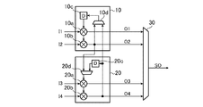
- FIG. FIG. 5 is a configuration diagram of the parallel differential encoding circuit according to the second embodiment.
- the parallel differential encoding circuit according to the second embodiment includes a first differential encoding circuit 10, a second differential encoding circuit 20, and a multiplexing circuit 30.
- the first differential encoding circuit 10 and the second differential encoding circuit 20 are configured by exclusive OR circuits 10a and 10b, a delay element 10c, and exclusive OR circuits 20a and 20a, respectively.
- the configurations of the exclusive OR circuits 10a and 10b, the delay element 10c, the exclusive OR circuits 20a and 20b, and the delay element 20c are the same as those of the exclusive OR circuits 1a and 1b and the delay element 1c of the first embodiment. This is the same as the exclusive OR circuits 2a, 2b and 2c.
- the selection circuit 10d includes parallel output data O4 of the exclusive OR circuit 20b in the second differential encoding circuit 20, and parallel output data O2 of the exclusive OR circuit 10b in the first differential encoding circuit 10. This is a circuit for selecting and supplying the selected output to the delay element 10c.
- the selection circuit 20d performs exclusive processing on the data obtained by delaying the parallel output data O4 of the exclusive OR circuit 20b in the second differential encoding circuit 20 by the delay element 20c and the first differential encoding circuit 10. This is a circuit for selecting the parallel output data O2 of the logical OR circuit 10b and supplying the selected output to the exclusive OR circuit 20a.
- the multiplexing circuit 30 is a 4: 1 MUX that time-multiplexes four parallel output signals, and the parallel output data O1, O3, and O2 at four times the speed. , O4 are output to the serial output SO in this order.
- the selection circuit 10d in the first differential encoding circuit 10 selects the parallel output data O4 side, and the selection circuit 20d in the second differential encoding circuit 20 is in parallel.
- the output data O2 side it is possible to output a signal subjected to 1-symbol delay differential encoding as the serial output SO after being multiplexed by the multiplexing circuit 30.
- the selection circuit 10d selects the parallel output data O2 side, and the selection circuit 20d selects the parallel output data O4 side (the output data side of the delay element 20c).
- An encoding circuit configuration can be obtained.
- the output data of the n-th row of the second differential encoding circuit and the n-th row of the first differential encoding circuit are obtained by delaying the first selection circuit for selecting output data, the n-th row output data of the first differential encoding circuit, and the n-th row output data of the second differential encoding circuit And a second selection circuit for selecting data, and the first differential encoding circuit delays the output of the first selection circuit to differentially encode the input data of the first row,
- the APol-DPSK method using the 2-symbol delay differential encoding and the 1-symbol delay difference are used.
- the same LSI and FPG Share of the circuit at an internal it is possible to achieve reduction and suppression of the power consumption of the circuit scale.
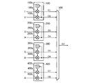
- FIG. 6 is a configuration diagram illustrating the parallel differential encoding circuit according to the third embodiment.
- the parallel differential encoding circuit of the third embodiment includes a first differential encoding circuit 100, a second differential encoding circuit 200, a third differential encoding circuit 300, and a fourth differential encoding.
- a circuit 400 is provided.
- the first differential encoding circuit 100 to the fourth differential encoding circuit 400 are the same as the first differential encoding circuit 1 and the second differential encoding circuit 2 in the first embodiment, respectively.
- a differential encoding circuit for DPSK which calculates from two rows of parallel input data I1 to I8 and outputs two rows of parallel output data O1 to O8.
- the first differential encoding circuit 100 includes exclusive OR circuits 100a and 100b and a delay element 100c
- the second differential encoding circuit 200 includes the exclusive OR circuits 200a and 200b and a delay
- the third differential encoding circuit 300 includes the exclusive OR circuits 300a and 300b and the delay element 300c
- the fourth differential encoding circuit 400 includes the exclusive OR circuit 400a. , 400b and a delay element 400c.
- the multiplexing circuit 500 is an 8: 1 MUX that time-multiplexes eight parallel output signals, and outputs the serial output SO in the order of O1, O3, O5, O7, O2, O4, O6, and O8 at eight times the speed. Output.
- the first differential encoding circuit 100 to the fourth differential encoding circuit 400 operate from two rows of parallel input data I1 and I2, I3 and I4, I5 and I6, and I7 and I8, respectively.
- the parallel output data O1 and O2, O3 and O4, O5 and O6, and O7 and O8 are output.
- the multiplexing circuit 500 outputs the serial output SO in the order of O1, O3, O5, O7, O2, O4, O6, and O8.
- a 4-symbol differentially encoded signal that is decoded into transmission data by the 4-symbol delay detector is output to the serial output SO.
- the parallel differential encoding circuit is a parallel differential encoding circuit that generates parallel output data by differentially encoding parallel input data, and includes n (2 A first differential encoding circuit that differentially encodes parallel input data of ⁇ n and n are integers to generate parallel output data of n (2 ⁇ n, n is an integer) rows, and n (2 A second differential encoding circuit that differentially encodes parallel input data of ⁇ n and n are integers to generate parallel output data of n (2 ⁇ n, n is an integer) rows, and n (2 A third differential encoding circuit that differentially encodes parallel input data of ⁇ n and n are integers to generate parallel output data of n (2 ⁇ n, n is an integer) rows, and n (2 ⁇ n, n is an integer) fourth differential code for differentially encoding parallel input data of n rows and generating parallel output data of n (2 ⁇ n, n is an integer) rows Circuit, parallel output
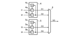
- FIG. 7 is a configuration diagram showing the parallel differential encoding circuit according to the fourth embodiment corresponding to the 2-symbol delay.
- the parallel differential encoding circuit according to the fourth embodiment includes a first differential encoding circuit 4, a second differential encoding circuit 5, and a multiplexing circuit 6.
- the first differential encoding circuit 4 is a DQPSK differential encoding circuit, which calculates from two rows and two sets of parallel input data I1 (I1I, I1Q) and I2 (I2I, I2Q), A set of parallel output data O1 (O1I, O1Q), O2 (O2I, O2Q) is output.
- the first differential encoding circuit 4 is composed of logic circuits 4a and 4b and a delay element 4c, and delays two sets of parallel output data O2 (O2I and O2Q) by the delay element 4c, thereby providing two sets of parallel inputs. It has a feedback path for performing differential encoding operation with data I1 (I1I, I1Q).
- the second differential encoding circuit 5 is a DQPSK differential encoding circuit, which calculates from two rows and two sets of parallel input data I3 (I3I, I3Q) and I4 (I4I, I4Q), A set of parallel output data O3 (O3I, O3Q), O4 (O4I, O4Q) is output.
- the second differential encoding circuit 5 includes logic circuits 5a, 5b and a delay element 5c, and delays two sets of parallel output data O4 (O4I, O4Q). Delayed by the element 5c, has a feedback path for performing differential encoding operation with two sets of parallel input data I3 (I3I, I3Q).
- the multiplexing circuit 6 is a 4: 1 MUX for time-multiplexing four parallel output signals, and two sets of serial output SOs in the order of O1I, O1Q, O3I, O3Q, O2I, O2Q, O4I, O4Q at a quadruple speed. (SOI, SOQ).
- FIG. 8 shows details of the logic circuits 4a, 4b, 5a, and 5b.
- the illustrated logic circuit is composed of an AND circuit and an OR circuit.
- DQPSK digital quadrature phase modulation
- two sets of input signals II and IQ are input as feedback signals DI and DQ from two sets of delay elements or adjacent output signals, and phase modulation for DQPSK is performed.
- the output data OI and OQ for outputting to the positive phase component and the quadrature component of the device are calculated.
- serial outputs SOI and SOQ generated in FIG. 7 are 2-symbol differentially encoded signals as in the first embodiment, and the original transmission data sequence is decoded by the 2-symbol delay detector used in the DQPSK decoder. it can.
- differential encoding circuit corresponding to the DQPSK system can be realized by a method other than the circuit connection method shown in the fourth embodiment, and the effect of the fourth embodiment is not limited to the configuration shown in FIG. .
- the parallel differential encoding circuit according to the fourth embodiment is a parallel differential encoding circuit that generates parallel output data by differentially encoding parallel input data, and includes 2 bits. N (2 ⁇ n, n is an integer) rows of parallel input data differentially encoded to generate n (2 ⁇ n, n is an integer) rows of parallel output data.
- the first differential encoding circuit and n (2 ⁇ n, n is an integer) rows of parallel input data having 2 bits as a set are differentially encoded to form 2 bits as a set of n (2 ⁇ n, n is an integer) the second differential encoding circuit for generating parallel output data of rows, the parallel output data of the first differential encoding circuit and the parallel output data of the second differential encoding circuit alternately.
- a multiplexing circuit that multiplexes and outputs is provided, so that differential encoding corresponding to 2-symbol delay detection can be realized. , It is possible transmission distance stretching of the optical signal by APol-DQPSK scheme.
- the parallel differential encoding circuit relates to a configuration for supporting a long-distance transmission format that requires 2-bit delay detection, such as the Apol-DPSK method and the Apol-DQPSK method. It is suitable for use in communication devices such as optical fiber transmission devices and wireless transceivers.
Landscapes
- Engineering & Computer Science (AREA)
- Computer Networks & Wireless Communication (AREA)
- Signal Processing (AREA)
- Physics & Mathematics (AREA)
- Electromagnetism (AREA)
- Theoretical Computer Science (AREA)
- Digital Transmission Methods That Use Modulated Carrier Waves (AREA)
- Dc Digital Transmission (AREA)
Abstract
第1の差動符号化回路1は、n行の並列入力データを差動符号化してn行の並列出力データを生成する。第2の差動符号化回路2は、n行の並列入力データを差動符号化してn行の並列出力データを生成する。多重化回路3は、第1の差動符号化回路1の並列出力データと第2の差動符号化回路2の並列出力データを交互に多重して出力する。
Description
この発明は、光ファイバ伝送装置、無線送受信機などの通信装置に使用される、並列差動符号化回路に関するものである。
近年、光通信システムにおいて、超高速大容量の信号伝送を実現する方式としてDifferential Quadrature Phase Shift Keying(DQPSK)等の位相変調技術やDual-Polarized Quadrature Phase Shift Keying(DP-QPSK)等のデジタルコヒーレント技術が積極的に研究されている。また伝送距離の更なる延伸化を目指し、伝送する交互のシンボルに異なる直交偏波を用いるAlternate Polarization Differential Phase Shift keying(Apol-DPSK)といった方式も検討されている。
光DPSK、DQSPK方式では、受信機に、伝送する前後のシンボル間位相差を検出する遅延干渉計を利用した検波器を使用する。このため、送信機にて、予め送信データを位相差に割り当てる差動符号化回路またはプリコーダと呼ばれる回路が必要となる。また、デジタルコヒーレント方式においては、受信機が持つローカル光にて受信光の位相を検出するが、送信側での絶対位相が不明であり、データが復元できない。これを解消するため初期位相が不明でもデータ復元できる差動符号化を利用することもある。
例えば、従来のAlternate Polarization Differential Phase Shift keying(Apol-DPSK)方式では、1シンボル毎に直交する偏波を使用することにより、自己位相変調といった非線形効果による信号劣化への耐性を強めている。このシステムにおける受信機では1シンボルおきに受信される同一偏波の光信号を遅延干渉させてデータを抽出する必要がある。このため、通常のDPSK方式では前後1シンボル間の光信号位相差にデータを割り当てる差動符号化を実施するのに対し、Apol-DPSK方式では2シンボル間での差動符号化回路を使用する必要がある。
差動符号化処理は高速デジタル回路で実現されるが、位相差を演算するために直前に出力した光信号位相の情報を遅延素子にて保持しなければならない。このため、差動符号化回路中にシンボルレートで動作するフィードバックパスが存在することになる。光通信ではビットレートが40Gbps、100Gbpsと超高速であるため、このフィードバックパスは数十GHzで動作することが求められ、実装が非常に困難になるという問題があった。
この問題に対応するために、高速動作する様々な差動符号化回路が考案されている。例えば、特許文献1では差動符号化回路を並列展開することで、デジタル回路の動作速度を低減し、一般的なLSIプロセスでのデジタル回路実装を可能にするという回路作成技術が開示されている。
しかしながら、上記特許文献1に記載されたような並列差動符号化回路では、差動符号化処理されたデータが多重後1シンボル毎に出力される。このため、Apol-DPSK方式、Apol-DQPSK方式のような2ビット遅延検波を必要とする長距離伝送用フォーマットには対応できないという問題点があった。
この発明は、かかる問題を解決するためになされたもので、長距離伝送用フォーマットに適した並列差動符号化回路を得ることを目的としている。
この発明に係る並列差動符号化回路は、並列入力データを差動符号化して、並列出力データを生成する並列差動符号化回路であって、n(2≦n、nは整数)行の並列入力データを差動符号化して、n(2≦n、nは整数)行の並列出力データを生成する第1の差動符号化回路と、n(2≦n、nは整数)行の並列入力データを差動符号化して、n(2≦n、nは整数)行の並列出力データを生成する第2の差動符号化回路と、第1の差動符号化回路の並列出力データと第2の差動符号化回路の並列出力データを交互に多重して出力する多重化回路を備えたものである。
これにより、長距離伝送用フォーマットに適した並列差動符号化回路を得ることができる。
以下、この発明をより詳細に説明するために、この発明を実施するための形態について、添付の図面に従って説明する。
実施の形態1.
図1は、本実施の形態による並列差動符号化回路を示す構成図である。
本実施の形態の並列差動符号化回路は、第1の差動符号化回路1、第2の差動符号化回路2、多重化回路3を備えている。第1の差動符号化回路1および第2の差動符号化回路2は、それぞれDPSK用差動符号化回路である。第1の差動符号化回路1は、2行の並列入力データI1,I2から演算して、2行の並列出力データO1,O2を出力する。第1の差動符号化回路1は、排他的論理和回路1a,1bと遅延素子1cとから構成され、排他的論理和回路1bからの並列出力データO2を遅延素子1cにて遅延させ、排他的論理和回路1aで、並列入力データI1との排他的論理和演算を行うフィードバックパスを持つ。第2の差動符号化回路2の構成も第1の差動符号化回路1と同様であり、2行の並列入力データI3、I4から演算して、2行の並列出力データO3,O4を出力する。第2の差動符号化回路2においても、排他的論理和回路2a,2bと遅延素子2cとから構成され、排他的論理和回路2bからの並列出力データO4を遅延素子2cにて遅延させ、排他的論理和回路2aで、並列入力データI3との排他的論理和演算を行うフィードバックパスを持つ。多重化回路3は、4系統の並列出力信号を時間多重する4:1MUXであり、4倍の速度で並列出力データO1,O3,O2,O4の順にシリアル出力SOに出力する。
図2は一般的なDPSK方式における送信データ並びに光位相との関係を説明するタイミングチャートであり、図3は実施の形態1の動作を説明するためのタイミングチャートである。
DPSK方式では送信データを位相変調器にて変調する送信光位相の位相差に割り当てる。例えば図2では送信データの‘0’を位相変化なし、‘1’を位相反転とみなすと、送信データ系列“01101011011101000010”に対して、1シンボル差動符号化後のデータ系列は“01001101101001111100”となる。位相変調器で‘0’を位相‘0’なし、‘1’を位相‘π’へ変換すると送信光位相系列は“00π00ππ0ππ0π00πππππ00”となる。受信機では遅延検波により位相差が検出されることから、もし前後シンボルが“00”、“ππ”ならば検出位相は“0”、もし“0π”、“π0”ならば検出位相は“π”となる。このことから、図2の例では遅延検波後検出位相は“0ππ0π0ππ0πππ0π0000π0”となる。これを電気信号に変換し、データを復元すると、元の送信データ系列と等しい“01101011011101000010”が得られる。
DPSK方式では送信データを位相変調器にて変調する送信光位相の位相差に割り当てる。例えば図2では送信データの‘0’を位相変化なし、‘1’を位相反転とみなすと、送信データ系列“01101011011101000010”に対して、1シンボル差動符号化後のデータ系列は“01001101101001111100”となる。位相変調器で‘0’を位相‘0’なし、‘1’を位相‘π’へ変換すると送信光位相系列は“00π00ππ0ππ0π00πππππ00”となる。受信機では遅延検波により位相差が検出されることから、もし前後シンボルが“00”、“ππ”ならば検出位相は“0”、もし“0π”、“π0”ならば検出位相は“π”となる。このことから、図2の例では遅延検波後検出位相は“0ππ0π0ππ0πππ0π0000π0”となる。これを電気信号に変換し、データを復元すると、元の送信データ系列と等しい“01101011011101000010”が得られる。
図1において、例えば送信データ系列“00101010001100000010”を先頭から順に繰り返し並列入力データI1,I2,I3,I4に“01000”、“10110”、“11101”、“00100”として入力するとする。この時、差動符号化回路で演算された結果の並列データ出力O1,O2,O3,O4は、図3に示す通りそれぞれ“00010”、“10100”、“10101”、“10001”となる。このデータが多重化回路3にて多重化され、シリアル出力SOから“01110000011010000101”の順に出力される。
図3にて示される多重化出力を位相変調器にて変調し、2シンボル遅延検波器にて位相差を検出した場合の系列を図4に示す。これを時分割分離して、“1000”、“10100”、“1101”、“00100”と戻すことで、元の送信データ系列を復元できる。なお、位相変調器や2シンボル遅延検波器および時分割分離する構成についてはその図示を省略している。
また、DPSK方式に対応した差動符号化回路は本実施の形態1に示した排他的論理和と遅延素子の接続方法以外でも実現でき、本実施の形態1の効果は図1に示す構成だけに限られるものではない。
以上説明したように、この実施の形態1の並列差動符号化回路においては、並列入力データを差動符号化して、並列出力データを生成する並列差動符号化回路であって、n(2≦n、nは整数)行の並列入力データを差動符号化して、n(2≦n、nは整数)行の並列出力データを生成する第1の差動符号化回路と、n(2≦n、nは整数)行の並列入力データを差動符号化して、n(2≦n、nは整数)行の並列出力データを生成する第2の差動符号化回路と、第1の差動符号化回路の並列出力データと第2の差動符号化回路の並列出力データを交互に多重して出力する多重化回路を備えたので、2シンボル遅延検波に対応した差動符号化を実現することができ、APol-DPSK方式による光信号の伝送距離延伸化が可能となる。
実施の形態2.
図5は、実施の形態2における並列差動符号化回路の構成図である。
実施の形態2の並列差動符号化回路は、第1の差動符号化回路10、第2の差動符号化回路20、多重化回路30を備えている。第1の差動符号化回路10および第2の差動符号化回路20は、実施の形態1と同様に、それぞれ排他的論理和回路10a,10b、遅延素子10cおよび排他的論理和回路20a,20b、遅延素子20cを備えていると共に、選択回路10dおよび20dをそれぞれ備えている。ここで、排他的論理和回路10a,10b、遅延素子10cと排他的論理和回路20a,20b、遅延素子20cの構成は、実施の形態1の排他的論理和回路1a,1b、遅延素子1cと排他的論理和回路2a,2b、2cと同様である。
選択回路10dは、第2の差動符号化回路20における排他的論理和回路20bの並列出力データO4と、第1の差動符号化回路10における排他的論理和回路10bの並列出力データO2とを選択し、その選択出力を遅延素子10cに与えるための回路である。また、選択回路20dは、第2の差動符号化回路20における排他的論理和回路20bの並列出力データO4を遅延素子20cで遅延させたデータと、第1の差動符号化回路10における排他的論理和回路10bの並列出力データO2とを選択し、その選択出力を排他的論理和回路20aに与えるための回路である。また、多重化回路30は、実施の形態1の多重化回路3と同様に、4系統の並列出力信号を時間多重する4:1MUXであり、4倍の速度で並列出力データO1,O3,O2,O4の順にシリアル出力SOに出力する。
このように構成された実施の形態2では、第1の差動符号化回路10における選択回路10dが並列出力データO4側を選択し、第2の差動符号化回路20における選択回路20dが並列出力データO2側を選択することにより、多重化回路30で多重した後のシリアル出力SOとして1シンボル遅延差動符号化された信号を出力することができる。なお、選択回路10dが並列出力データO2側を選択し、選択回路20dが並列出力データO4側(遅延素子20cの出力データ側)を選択することにより実施の形態1と同等の2シンボル遅延差動符号化回路構成を得ることができる。
以上説明したように、この実施の形態2の並列差動符号化回路では、第2の差動符号化回路のn行目の出力データと、第1の差動符号化回路のn行目の出力データとを選択する第1の選択回路と、第1の差動符号化回路のn行目の出力データと、第2の差動符号化回路のn行目の出力データを遅延させた出力データとを選択する第2の選択回路とを備え、第1の差動符号化回路では、第1の選択回路の出力を遅延させて1行目の入力データと差動符号化し、第2の差動符号化回路では、第2の選択回路の出力を1行目の入力データと差動符号化するようにしたので、2シンボル遅延差動符号化を用いるAPol-DPSK方式並びに1シンボル遅延差動符号化を用いる通常のDPSK方式の両方に対応が可能であり、同一のLSIやFPGA内にて回路を共有化して、回路規模の削減並びに消費電力の抑制を達成することができる。
実施の形態3.
図6は、実施の形態3の並列差動符号化回路を示す構成図である。
実施の形態3の並列差動符号化回路は、第1の差動符号化回路100、第2の差動符号化回路200、第3の差動符号化回路300、第4の差動符号化回路400を備えている。これら第1の差動符号化回路100~第4の差動符号化回路400は、それぞれ実施の形態1における第1の差動符号化回路1や第2の差動符号化回路2と同様のDPSK用差動符号化回路であり、2行の並列入力データI1~I8から演算して、2行の並列出力データO1~O8を出力する。即ち、第1の差動符号化回路100は、排他的論理和回路100a,100bと遅延素子100cで構成され、第2の差動符号化回路200は、排他的論理和回路200a,200bと遅延素子200cで構成され、第3の差動符号化回路300は、排他的論理和回路300a,300bと遅延素子300cで構成され、第4の差動符号化回路400は、排他的論理和回路400a,400bと遅延素子400cで構成されている。また、多重化回路500は、8系統の並列出力信号を時間多重する8:1MUXであり、8倍の速度でO1,O3,O5,O7,O2,O4,O6,O8の順にシリアル出力SOに出力する。
次に、実施の形態3の動作について説明する。
第1の差動符号化回路100~第4の差動符号化回路400は、それぞれ2行の並列入力データI1とI2、I3とI4、I5とI6、I7とI8から演算して、2行の並列出力データO1とO2、O3とO4、O5とO6、O7とO8を出力する。多重化回路500は、O1,O3,O5,O7,O2,O4,O6,O8の順にシリアル出力SOに出力する。これにより、シリアル出力SOには、4シンボル遅延検波器で送信データに復号される、4シンボル差動符号化信号が出力される。
第1の差動符号化回路100~第4の差動符号化回路400は、それぞれ2行の並列入力データI1とI2、I3とI4、I5とI6、I7とI8から演算して、2行の並列出力データO1とO2、O3とO4、O5とO6、O7とO8を出力する。多重化回路500は、O1,O3,O5,O7,O2,O4,O6,O8の順にシリアル出力SOに出力する。これにより、シリアル出力SOには、4シンボル遅延検波器で送信データに復号される、4シンボル差動符号化信号が出力される。
以上説明したように、実施の形態3の並列差動符号化回路によれば、並列入力データを差動符号化して、並列出力データを生成する並列差動符号化回路であって、n(2≦n、nは整数)行の並列入力データを差動符号化して、n(2≦n、nは整数)行の並列出力データを生成する第1の差動符号化回路と、n(2≦n、nは整数)行の並列入力データを差動符号化して、n(2≦n、nは整数)行の並列出力データを生成する第2の差動符号化回路と、n(2≦n、nは整数)行の並列入力データを差動符号化して、n(2≦n、nは整数)行の並列出力データを生成する第3の差動符号化回路と、n(2≦n、nは整数)行の並列入力データを差動符号化して、n(2≦n、nは整数)行の並列出力データを生成する第4の差動符号化回路と、第1の差動符号化回路の並列出力データと第2の差動符号化回路の並列出力データと第3の差動符号化回路の並列出力データと第4の差動符号化回路の並列出力データを交互に多重して出力する多重化回路を備えたので、4つの差動符号化回路の出力を多重化出力することから、4シンボル差動符号化信号を作成することができ、例えば、受信機において4シンボル離れた信号同士による遅延検波を行う、雑音を抑制することが可能な伝送方式を用いることが可能で、伝送距離を伸ばすことができるといった効果がある。
実施の形態4.
図7は、2シンボル遅延に対応した実施の形態4の並列差動符号化回路を示す構成図である。
実施の形態4の並列差動符号化回路は、第1の差動符号化回路4と第2の差動符号化回路5と、多重化回路6とを備えている。第1の差動符号化回路4は、DQPSK用差動符号化回路であり、2行2組の並列入力データI1(I1I,I1Q)、I2(I2I,I2Q)から演算して、2行2組の並列出力データO1(O1I,O1Q)、O2(O2I,O2Q)を出力する。第1の差動符号化回路4は、論理回路4a,4bと遅延素子4cとから構成され、2組の並列出力データO2(O2I,O2Q)を遅延素子4cにて遅延させ、2組並列入力データI1(I1I,I1Q)との差動符号化演算を行うフィードバックパスを持つ。
第2の差動符号化回路5は、DQPSK用差動符号化回路であり、2行2組の並列入力データI3(I3I,I3Q)、I4(I4I,I4Q)から演算して、2行2組の並列出力データO3(O3I,O3Q)、O4(O4I,O4Q)を出力する。第2の差動符号化回路5も、第1の差動符号化回路4と同様に論理回路5a,5bと遅延素子5cから構成され、2組の並列出力データO4(O4I,O4Q)を遅延素子5cにて遅延させ、2組の並列入力データI3(I3I,I3Q)との差動符号化演算を行うフィードバックパスを持つ。多重化回路6は、4系統の並列出力信号を時間多重する4:1MUXであり、4倍の速度でO1I,O1Q、O3I,O3Q、O2I,O2Q、O4I,O4Qの順に2組のシリアル出力SO(SOI,SOQ)に出力する。
図8に論理回路4a,4b、5a,5bの詳細を示す。
図示の論理回路はAND回路とOR回路とからなり、DQPSK方式では2組の入力信号II,IQを2組の遅延素子からのフィードバック信号DI,DQまたは隣接出力信号を入力として、DQPSK用位相変調器の正相成分、直交成分に出力するための出力データOI,OQを演算する。
図示の論理回路はAND回路とOR回路とからなり、DQPSK方式では2組の入力信号II,IQを2組の遅延素子からのフィードバック信号DI,DQまたは隣接出力信号を入力として、DQPSK用位相変調器の正相成分、直交成分に出力するための出力データOI,OQを演算する。
図7にて生成されたシリアル出力SOI,SOQは、実施の形態1と同様に2シンボル差動符号化信号となり、DQPSKデコーダで使用される2シンボル遅延検波器にて元の送信データ系列を復号できる。
また、DQPSK方式に対応した差動符号化回路は本実施の形態4に示した回路の接続方法以外でも実現でき、本実施の形態4の効果は図7に示す構成だけに限られるものではない。
以上説明したように、この実施の形態4の並列差動符号化回路によれば、並列入力データを差動符号化して、並列出力データを生成する並列差動符号化回路であって、2ビットを組とするn(2≦n、nは整数)行の並列入力データを差動符号化して、2ビットを組とするn(2≦n、nは整数)行の並列出力データを生成する第1の差動符号化回路と、2ビットを組とするn(2≦n、nは整数)行の並列入力データを差動符号化して、2ビットを組とするn(2≦n、nは整数)行の並列出力データを生成する第2の差動符号化回路と、第1の差動符号化回路の並列出力データと第2の差動符号化回路の並列出力データを交互に多重して出力する多重化回路を備えたので、2シンボル遅延検波に対応した差動符号化を実現することができ、APol-DQPSK方式による光信号の伝送距離延伸化が可能となる。
なお、本願発明はその発明の範囲内において、各実施の形態の自由な組み合わせ、あるいは各実施の形態の任意の構成要素の変形、もしくは各実施の形態において任意の構成要素の省略が可能である。
以上のように、この発明に係る並列差動符号化回路は、Apol-DPSK方式、Apol-DQPSK方式のような2ビット遅延検波を必要とする長距離伝送用フォーマットには対応するための構成に関するものであり、光ファイバ伝送装置や無線送受信機などの通信装置に用いるのに適している。
1,4,10,100 第1の差動符号化回路、2,5,20,200 第2の差動符号化回路、3,6,30 多重化回路、10d,20d 選択回路、300 第3の差動符号化回路、400 第4の差動符号化回路、500 多重化回路。
Claims (4)
- 並列入力データを差動符号化して、並列出力データを生成する並列差動符号化回路であって、
n(2≦n、nは整数)行の並列入力データを差動符号化して、n(2≦n、nは整数)行の並列出力データを生成する第1の差動符号化回路と、
n(2≦n、nは整数)行の並列入力データを差動符号化して、n(2≦n、nは整数)行の並列出力データを生成する第2の差動符号化回路と、
前記第1の差動符号化回路の並列出力データと前記第2の差動符号化回路の並列出力データを交互に多重して出力する多重化回路を備えることを特徴とした並列差動符号化回路。 - 第2の差動符号化回路のn行目の出力データと、第1の差動符号化回路のn行目の出力データとを選択する第1の選択回路と、
前記第1の差動符号化回路のn行目の出力データと、前記第2の差動符号化回路のn行目の出力データを遅延させた出力データとを選択する第2の選択回路とを備え、
前記第1の差動符号化回路では、前記第1の選択回路の出力を遅延させて1行目の入力データと差動符号化し、
前記第2の差動符号化回路では、前記第2の選択回路の出力を1行目の入力データと差動符号化することを特徴とする請求項1記載の並列差動符号化回路。 - 並列入力データを差動符号化して、並列出力データを生成する並列差動符号化回路であって、
n(2≦n、nは整数)行の並列入力データを差動符号化して、n(2≦n、nは整数)行の並列出力データを生成する第1の差動符号化回路と、
n(2≦n、nは整数)行の並列入力データを差動符号化して、n(2≦n、nは整数)行の並列出力データを生成する第2の差動符号化回路と、
n(2≦n、nは整数)行の並列入力データを差動符号化して、n(2≦n、nは整数)行の並列出力データを生成する第3の差動符号化回路と、
n(2≦n、nは整数)行の並列入力データを差動符号化して、n(2≦n、nは整数)行の並列出力データを生成する第4の差動符号化回路と、
前記第1の差動符号化回路の並列出力データと前記第2の差動符号化回路の並列出力データと前記第3の差動符号化回路の並列出力データと前記第4の差動符号化回路の並列出力データを交互に多重して出力する多重化回路を備えることを特徴とする並列差動符号化回路。 - 並列入力データを差動符号化して、並列出力データを生成する並列差動符号化回路であって、
2ビットを組とするn(2≦n、nは整数)行の並列入力データを差動符号化して、2ビットを組とするn(2≦n、nは整数)行の並列出力データを生成する第1の差動符号化回路と、
2ビットを組とするn(2≦n、nは整数)行の並列入力データを差動符号化して、2ビットを組とするn(2≦n、nは整数)行の並列出力データを生成する第2の差動符号化回路と、
前記第1の差動符号化回路の並列出力データと前記第2の差動符号化回路の並列出力データを交互に多重して出力する多重化回路を備えることを特徴とした並列差動符号化回路。
Priority Applications (5)
| Application Number | Priority Date | Filing Date | Title |
|---|---|---|---|
| EP10860522.1A EP2651086A4 (en) | 2010-12-06 | 2010-12-06 | Parallel difference-encoding circuits |
| CN201080070541.1A CN103229474B (zh) | 2010-12-06 | 2010-12-06 | 并行差分编码电路 |
| JP2012547595A JP5279959B2 (ja) | 2010-12-06 | 2010-12-06 | 並列差動符号化回路 |
| PCT/JP2010/007085 WO2012077155A1 (ja) | 2010-12-06 | 2010-12-06 | 並列差動符号化回路 |
| US13/823,158 US8717205B2 (en) | 2010-12-06 | 2010-12-06 | Parallel differential encoding circuits |
Applications Claiming Priority (1)
| Application Number | Priority Date | Filing Date | Title |
|---|---|---|---|
| PCT/JP2010/007085 WO2012077155A1 (ja) | 2010-12-06 | 2010-12-06 | 並列差動符号化回路 |
Publications (1)
| Publication Number | Publication Date |
|---|---|
| WO2012077155A1 true WO2012077155A1 (ja) | 2012-06-14 |
Family
ID=46206679
Family Applications (1)
| Application Number | Title | Priority Date | Filing Date |
|---|---|---|---|
| PCT/JP2010/007085 WO2012077155A1 (ja) | 2010-12-06 | 2010-12-06 | 並列差動符号化回路 |
Country Status (5)
| Country | Link |
|---|---|
| US (1) | US8717205B2 (ja) |
| EP (1) | EP2651086A4 (ja) |
| JP (1) | JP5279959B2 (ja) |
| CN (1) | CN103229474B (ja) |
| WO (1) | WO2012077155A1 (ja) |
Families Citing this family (1)
| Publication number | Priority date | Publication date | Assignee | Title |
|---|---|---|---|---|
| JP7367280B2 (ja) * | 2019-07-14 | 2023-10-24 | ヴァレンス セミコンダクター リミテッド | 8b10b pam4エンコーディング |
Citations (3)
| Publication number | Priority date | Publication date | Assignee | Title |
|---|---|---|---|---|
| JPH11122205A (ja) * | 1997-10-14 | 1999-04-30 | Nec Corp | 符号変換機能を備えた2値信号多重装置及び符号変換機能を備えた2値信号分離装置 |
| JP2007067904A (ja) * | 2005-08-31 | 2007-03-15 | Mitsubishi Electric Corp | パラレルプリコーダ回路 |
| JP2007074167A (ja) * | 2005-09-05 | 2007-03-22 | Mitsubishi Electric Corp | パラレルプリコーダ回路 |
Family Cites Families (6)
| Publication number | Priority date | Publication date | Assignee | Title |
|---|---|---|---|---|
| JPH0311235A (ja) | 1989-06-08 | 1991-01-18 | Matsushita Electric Ind Co Ltd | 加熱装置 |
| US5233630A (en) * | 1991-05-03 | 1993-08-03 | Qualcomm Incorporated | Method and apparatus for resolving phase ambiguities in trellis coded modulated data |
| JP3474794B2 (ja) * | 1999-02-03 | 2003-12-08 | 日本電信電話株式会社 | 符号変換回路及び符号変換多重化回路 |
| GB2383705B (en) * | 2001-11-30 | 2005-03-30 | Marconi Optical Components Ltd | Optical coding system |
| WO2007001090A1 (ja) * | 2005-06-28 | 2007-01-04 | Nec Corporation | Dpsk変復調方法、これを用いた光通信装置および光通信システム |
| CN101478347B (zh) * | 2009-01-08 | 2011-04-13 | 上海交通大学 | 无反馈回路的光差分正交移相键控调制器的预编码器 |
-
2010
- 2010-12-06 US US13/823,158 patent/US8717205B2/en not_active Expired - Fee Related
- 2010-12-06 WO PCT/JP2010/007085 patent/WO2012077155A1/ja active Application Filing
- 2010-12-06 CN CN201080070541.1A patent/CN103229474B/zh not_active Expired - Fee Related
- 2010-12-06 JP JP2012547595A patent/JP5279959B2/ja not_active Expired - Fee Related
- 2010-12-06 EP EP10860522.1A patent/EP2651086A4/en not_active Withdrawn
Patent Citations (4)
| Publication number | Priority date | Publication date | Assignee | Title |
|---|---|---|---|---|
| JPH11122205A (ja) * | 1997-10-14 | 1999-04-30 | Nec Corp | 符号変換機能を備えた2値信号多重装置及び符号変換機能を備えた2値信号分離装置 |
| JP3011235B2 (ja) | 1997-10-14 | 2000-02-21 | 日本電気株式会社 | 符号変換機能を備えた2値信号多重装置及び符号変換機能を備えた2値信号分離装置 |
| JP2007067904A (ja) * | 2005-08-31 | 2007-03-15 | Mitsubishi Electric Corp | パラレルプリコーダ回路 |
| JP2007074167A (ja) * | 2005-09-05 | 2007-03-22 | Mitsubishi Electric Corp | パラレルプリコーダ回路 |
Non-Patent Citations (1)
| Title |
|---|
| See also references of EP2651086A4 |
Also Published As
| Publication number | Publication date |
|---|---|
| JP5279959B2 (ja) | 2013-09-04 |
| US20130181853A1 (en) | 2013-07-18 |
| EP2651086A1 (en) | 2013-10-16 |
| JPWO2012077155A1 (ja) | 2014-05-19 |
| EP2651086A4 (en) | 2017-08-02 |
| CN103229474B (zh) | 2015-08-26 |
| CN103229474A (zh) | 2013-07-31 |
| US8717205B2 (en) | 2014-05-06 |
Similar Documents
| Publication | Publication Date | Title |
|---|---|---|
| US10250333B2 (en) | Optical communication system and optical transmitter | |
| CN104969524B (zh) | 光传输系统、相位补偿方法以及光接收装置 | |
| US8594508B2 (en) | Optical transmission system | |
| US7643760B1 (en) | Direct detection differential polarization-phase-shift keying for high spectral efficiency optical communication | |
| JP5213991B2 (ja) | パルス振幅変調による光差分可変マルチレベル位相シフトキーイング(odvmpsk/pam)信号の生成及び検出のための方法及び装置 | |
| JPWO2008038337A1 (ja) | 光電界受信器および光伝送システム | |
| JP6120945B2 (ja) | 光伝送装置および光伝送方法 | |
| JPWO2011099589A1 (ja) | 位相偏差・搬送波周波数偏差補償装置および位相偏差・搬送波周波数偏差補償方法 | |
| JP4927617B2 (ja) | データ伝送装置および伝送符号の生成方法 | |
| JP6415787B2 (ja) | 光伝送方法及び光伝送システム | |
| US10651944B2 (en) | Optical transmitter, optical receiver, optical data transmission system, optical transmission method, and optical reception method | |
| JP5279959B2 (ja) | 並列差動符号化回路 | |
| JP5049198B2 (ja) | 光伝送システム | |
| WO2019048028A1 (en) | OPTICAL TRANSMITTER AND TRANSMISSION METHOD | |
| WO2017002178A1 (ja) | 光送信装置、光受信装置、光伝送システムおよび光伝送方法 | |
| US9621298B2 (en) | Method of optical data transmission using polarization division multiplexing and QPSK | |
| JP2021166364A (ja) | 信号処理装置 | |
| JP5116567B2 (ja) | 光受信装置 | |
| JP2014007562A (ja) | 光送受信システム及び光伝送方法 | |
| US11677475B2 (en) | Encoding and decoding communications traffic in a pulse amplitude modulation format and optical apparatus for same | |
| JP2012156749A (ja) | 光受信器 | |
| EP2252024B1 (en) | Swap tolerant coding and decoding circuits and methods | |
| JP4701949B2 (ja) | 位相情報発生装置、位相情報発生方法、送信機および受信機 | |
| Nordin et al. | Coherent Optical Communication Systems in Digital Signal Processing | |
| JP2005184103A (ja) | 変調方法および装置ならびに復調方法および装置 |
Legal Events
| Date | Code | Title | Description |
|---|---|---|---|
| 121 | Ep: the epo has been informed by wipo that ep was designated in this application |
Ref document number: 10860522 Country of ref document: EP Kind code of ref document: A1 |
|
| WWE | Wipo information: entry into national phase |
Ref document number: 2012547595 Country of ref document: JP |
|
| WWE | Wipo information: entry into national phase |
Ref document number: 13823158 Country of ref document: US |
|
| NENP | Non-entry into the national phase |
Ref country code: DE |