WO2012073465A1 - 静電誘導型変換素子 - Google Patents
静電誘導型変換素子 Download PDFInfo
- Publication number
- WO2012073465A1 WO2012073465A1 PCT/JP2011/006569 JP2011006569W WO2012073465A1 WO 2012073465 A1 WO2012073465 A1 WO 2012073465A1 JP 2011006569 W JP2011006569 W JP 2011006569W WO 2012073465 A1 WO2012073465 A1 WO 2012073465A1
- Authority
- WO
- WIPO (PCT)
- Prior art keywords
- ferroelectric
- conversion element
- electrostatic induction
- induction conversion
- electret
- Prior art date
- Legal status (The legal status is an assumption and is not a legal conclusion. Google has not performed a legal analysis and makes no representation as to the accuracy of the status listed.)
- Ceased
Links
Images

Classifications
-
- H—ELECTRICITY
- H01—ELECTRIC ELEMENTS
- H01G—CAPACITORS; CAPACITORS, RECTIFIERS, DETECTORS, SWITCHING DEVICES, LIGHT-SENSITIVE OR TEMPERATURE-SENSITIVE DEVICES OF THE ELECTROLYTIC TYPE
- H01G7/00—Capacitors in which the capacitance is varied by non-mechanical means; Processes of their manufacture
- H01G7/06—Capacitors in which the capacitance is varied by non-mechanical means; Processes of their manufacture having a dielectric selected for the variation of its permittivity with applied voltage, i.e. ferroelectric capacitors
-
- H—ELECTRICITY
- H01—ELECTRIC ELEMENTS
- H01G—CAPACITORS; CAPACITORS, RECTIFIERS, DETECTORS, SWITCHING DEVICES, LIGHT-SENSITIVE OR TEMPERATURE-SENSITIVE DEVICES OF THE ELECTROLYTIC TYPE
- H01G7/00—Capacitors in which the capacitance is varied by non-mechanical means; Processes of their manufacture
- H01G7/02—Electrets, i.e. having a permanently-polarised dielectric
- H01G7/025—Electrets, i.e. having a permanently-polarised dielectric having an inorganic dielectric
- H01G7/026—Electrets, i.e. having a permanently-polarised dielectric having an inorganic dielectric with ceramic dielectric
-
- H—ELECTRICITY
- H02—GENERATION; CONVERSION OR DISTRIBUTION OF ELECTRIC POWER
- H02N—ELECTRIC MACHINES NOT OTHERWISE PROVIDED FOR
- H02N1/00—Electrostatic generators or motors using a solid moving electrostatic charge carrier
- H02N1/06—Influence generators
- H02N1/08—Influence generators with conductive charge carrier, i.e. capacitor machines
Definitions
- the present invention relates to an electrostatic induction conversion element that converts electrical energy and kinetic energy.
- fluorine-based resins such as polytetrafluoroethylene, Teflon (registered trademark), and Cytop (registered trademark) are mainly used as dielectrics used in electrets (Patent Documents 1 to 4).
- the resin material has a problem in heat resistance and cannot be applied to a use environment at a temperature higher than the heat resistant temperature of the resin material (for example, 150 ° C. or higher).
- the higher the surface charge density after charging and the lower the dielectric constant the better.
- these resin materials have a low dielectric constant, the surface charge density cannot be increased so much.
- the surface charge density of the fluorine-based resin material is generally about 0.005 ⁇ C / cm 2 , and even a high one is about 0.15 ⁇ C / cm 2 .
- Patent Document 5 discloses a mechano-electric conversion element using a dielectric polarization plate made of a ferroelectric substance as an electret material having good heat resistance and high surface charge density as compared with a polymer material ( An electrostatic induction conversion element) is disclosed.
- Patent Document 6 uses, in an electrostatic device for power generation, a structure that avoids the influence of air on the electret, and uses a polled ferroelectric as the electret material in claim 4 and paragraph [0066], and It is described that the amount of power generation is large.
- a ferroelectric For the surface charge density of a ferroelectric material, its remanent polarization value is one measure.
- a ferroelectric has a large remanent polarization value and is considered to be 10 ⁇ C / cm 2 or more. Therefore, it is considered that a significantly higher electromechanical conversion efficiency can be achieved as compared with a polymer material.
- Patent Document 5 and Patent Document 6 sufficient electromechanical conversion efficiency is not yet obtained.
- the present invention has been made in view of the above circumstances, and an object thereof is to provide an electrostatic induction conversion element having high mechanical-electrical conversion efficiency.
- the electrostatic induction type conversion element of the present invention is an electrostatic induction type conversion element that converts electric energy and kinetic energy, and has a main surface made of a conductor and a dielectric formed on the main surface.
- the dielectric polarization body is made of a ferroelectric material having crystal orientation (may contain inevitable impurities).
- orientation rate F measured by the Lottgering method being 80% or more.
- the orientation rate F is represented by the following formula.
- F (%) (P ⁇ P0) / (1 ⁇ P0) ⁇ 100 (i)
- P is the ratio of the total reflection intensity from the orientation plane to the total reflection intensity.
- P is the sum ⁇ I (00l) of the reflection intensity I (00l) from the (00l) plane and the sum ⁇ I (hkl) of the reflection intensity I (hkl) from each crystal plane (hkl). ( ⁇ I (00l) / ⁇ I (hkl) ⁇ ).
- P I (001) / [I (001) + I (100) + I (101) + I (110) + I (111)].
- P0 is P of a sample having a completely random orientation.
- F 0%
- F 100%.
- the polarization direction of the ferroelectric is preferably substantially uniform, and the polarization direction is preferably the thickness direction of the ferroelectric.
- “the polarization direction is substantially uniform” means that the directions of the polarization axes are 80% or more.
- the ferroelectric is preferably a single crystal. Further, it is preferable that the remanent polarization value of the ferroelectric is 10 ⁇ C / cm 2 or more and the relative dielectric constant is 400 or less.
- the crystal structure of the ferroelectric is preferably a perovskite structure, a bismuth layered structure, or a tungsten bronze structure, and the ferroelectric is mainly composed of a perovskite oxide that does not contain lead. preferable.
- a perovskite oxide a bismuth-containing perovskite oxide is preferable.
- ferroelectric material As a preferable aspect of the ferroelectric material, a ferroelectric film formed on the base material can be cited.
- the electrostatic induction conversion element of the present invention uses an electret material made of a ferroelectric material having crystal orientation (may contain inevitable impurities) as the dielectric polarization body.
- the ferroelectric material having a large remanent polarization value is further oriented to form a dielectric polarization material, thereby not only having a very large surface charge density but also reducing the dielectric constant and increasing the dielectric constant.
- Mechanical-electrical conversion characteristics can be achieved.
- an electrostatic induction conversion element having higher heat resistance and higher mechanical-electric conversion efficiency than a resin material is provided. Can be provided.
- FIG. 1 is a schematic cross-sectional view of an electrostatic induction conversion element according to an embodiment of the present invention.
- the scales of the constituent elements of each part are appropriately changed and shown.
- the electrostatic induction conversion element 1 is composed of a lower electrode (base material) 21 and a ferroelectric material having crystal orientation formed on the lower electrode 21 (including inevitable impurities). It may be arranged so as to oppose the electret (dielectric polarization body) 10 and the surface 10s of the electret 10 via a gap space having a separation distance g, and the facing area A of the surface 10s of the electret 10 changes. And a counter electrode (electrode) 22 that moves relatively.
- the electret 10 has a large number of charges near the surface 10 s, and the lower electrode 21 and the counter electrode 22 are electrically connected to the load 30.
- the electrostatic induction conversion element 1 is an electrostatic induction conversion element that converts electric energy and kinetic energy, and induced charges are generated in the counter electrode 22 by an electrostatic field formed by the electret 10 having a large number of charges on the surface 10s. Is electrostatically induced, and the electret 10 and the counter electrode 22 move relative to each other so as to change the counter area A with the counter electrode 22, whereby an alternating current can be generated in the external circuit (load 30).
- the relative motion is not particularly limited as long as the facing area A changes, and a motion that causes an area change efficiently, such as a linear motion or a rotational motion, can be selected.
- the direction of the relative motion is preferably a direction in which the surface of the counter electrode 22 (the surface facing the electret 10) is parallel to the surface 10s of the electret 10 because a more efficient area change occurs.
- the lower electrode 21 is not particularly limited as long as one main surface (surface) is a base material made of a conductor that does not impair the crystal orientation of the electret 10 formed on the main surface.
- the electret 10 is a ferroelectric film formed on the lower electrode 21, the counter electrode 22 preferably has good lattice matching with the ferroelectric film to be formed may be a conductor. If it does not restrict
- the thicknesses of the lower electrode 21 and the counter electrode 22 are not particularly limited, and may be a minimum thickness for having sufficient conductivity for taking out electric charges generated by electrostatic induction.
- the thickness can be determined by the conductivity of the electrode material and the overall size of the electrostatic induction conversion element 1, and is preferably 50 to 10,000 nm, for example.
- Each electrode may have a multilayer structure.
- the ferroelectric constituting the electret 10 is not particularly limited as long as it is a ferroelectric having crystal orientation, and even if it is an organic ferroelectric, it is an inorganic ferroelectric. It doesn't matter. Since higher mechanical-electrical conversion efficiency can be obtained, it is preferable to use a ferroelectric having a high remanent polarization value. Further, from the viewpoint of heat resistance, an inorganic ferroelectric is preferable, and a ferroelectric having a higher Curie temperature is preferable.
- the mechanical-electric conversion characteristic (maximum power generation output P max ) of the electret 10 is defined by the following formula (1).
- ⁇ is the surface charge density of the electret
- n is the number of poles, that is, the number of electrets
- a (t) is the area of the conductor facing the electret (function of time)
- f is the frequency of the reciprocating motion of the conductor
- d is the thickness of the electret.
- G is the distance between the electret and the conductor
- ⁇ is the dielectric constant of the electret material.
- the electret 10 having higher mechanical-electrical conversion characteristics is a ferroelectric having a high surface charge density ⁇ , a large thickness, and a small relative dielectric constant.
- the surface charge density ⁇ can be estimated from the magnitude of the remanent polarization value. Therefore, it is preferable that the electret 10 is mainly composed of an inorganic ferroelectric that can give a large remanent polarization value.
- Examples of the crystal structure of an inorganic ferroelectric material that can provide a large remanent polarization value (excellent ferroelectricity) include a perovskite structure, a bismuth layered structure, and a tungsten bronze structure. Among these, a perovskite structure is preferable.
- the electret 10 has a ferroelectric polarization axis direction that is substantially uniform and that the direction is nearly parallel to the thickness direction.
- the electret 10 of this embodiment has crystal orientation. Therefore, the electret 10 that provides a large remanent polarization value can be obtained by controlling the crystal orientation so that the directions of the polarization axes of the ferroelectric material are substantially parallel to the thickness direction. In such a configuration, a single crystal or an epitaxial film is more preferable.
- perovskite type oxides having excellent ferroelectricity lead-based perovskite type oxides are known, but from the viewpoint of environmental impact, those based on perovskite type oxides not containing lead are preferred, and bismuth The containing perovskite oxide is more preferable.
- perovskite-type oxides include lead titanate, lead zirconate titanate (PZT), lead zirconate, lead lanthanum titanate, lead lanthanum zirconate titanate, lead zirconium titanate titanate niobate.
- Lead-containing compounds such as lead zirconium titanate nickel niobate and lead zirconium niobate titanate, and mixed crystals thereof;
- barium titanate (BTO) barium titanate
- strontium barium titanate bismuth sodium titanate
- bismuth potassium titanate sodium niobate
- potassium niobate potassium niobate
- lithium niobate etc.
- PX perovskite oxides
- A is an A-site element having an average ionic valence other than Pb and bivalent
- B is a B-site element having an average ionic valence of 3
- C is B having an average ionic valence greater than 3
- B and C are each one or more kinds of metal elements
- O is oxygen
- B and C have different compositions, 0.6 ⁇ x ⁇ 1.0, x-0 .2 ⁇ y ⁇ x
- the ratio of the total number of moles of the A-site element and the total number of moles of the B-site element to the number of moles of oxygen atoms is typically 1: 3, but within the range where a perovskite structure can be taken May deviate from 1: 3.
- the electret 10 is a ferroelectric whose composition is designed so that the relative dielectric constant becomes smaller in the structure having excellent ferroelectricity.
- a perovskite oxide such as PZT
- the remanent polarization value is 10 ⁇ C / cm 2 or more and the relative dielectric constant is 400 or less.
- a certain ferroelectric material is preferable.
- a suitable value of the thickness d of the electret 10 varies depending on the application of the electrostatic induction conversion element.
- Main applications of the electrostatic induction conversion element 1 include power generation elements, sensors such as microphones, pressure sensors, acceleration sensors, seismometers, and application elements thereof.
- the electret 10 is preferably thicker. It is preferable that the thickness of the electret 10 is designed in consideration of the required power generation amount and size depending on the application. Since the electrostatic induction conversion element of this embodiment has high mechanical-electrical conversion efficiency, it can achieve the same amount of power generation with a relatively thin film thickness as compared with conventional electret materials.
- the electret 10 is preferably a ferroelectric film formed on the lower electrode 21.
- the method for forming the ferroelectric film is not particularly limited, but it is preferable to use a vapor phase film forming method capable of making the polarization direction substantially uniform without performing polarization treatment.
- An example of such a film forming method is a sputtering method using plasma. The polarization process will be described below.
- the electret 10 has a large number of charges near the surface 10s.
- the electret 10 is a ferroelectric having crystal orientation. Therefore, in order to cause a large number of charges to exist in the vicinity of the surface 10, the ferroelectric may be polarized. By applying the polarization treatment, a large number of charges can be present in the vicinity of the surface 10s, and the electret 10 can be obtained.
- the polarization method of the electret 10 is not particularly limited, and examples thereof include a corona discharge treatment that is a general method. From the viewpoint of preventing characteristic deterioration due to depolarization, the coercive electric field value of the ferroelectric material constituting the electret 10 is preferably higher. Although it has been described that the Curie temperature of the ferroelectric material constituting the electret 10 is preferably higher at the portion described regarding the heat resistance, the Curie temperature is preferably higher from the viewpoint of characteristic deterioration due to depolarization.
- the ferroelectric film formed by the sputtering method depends on the composition of the film, but the direction of the polarization axis is substantially the same without special polarization treatment. There is a tendency to become a ferroelectric film having such a crystal orientation.
- lead zirconate titanate (Pb (Zr, Ti) O 3 : PZT) having high ferroelectricity has a substantially uniform spontaneous polarization axis in the as-depo state after sputtering film formation.
- Film c-axis alignment film ⁇ 001> orientation
- a high electric field is generated in the gap space such that the magnitude of the electric field is kV / mm or more
- discharge from the counter electrode 22 may cause the surface 10s of the electret 10 to be charged.
- surface charge is generated on the surface 10s of the electret 10, and the high polarization characteristics of the ferroelectric substance cannot be used effectively. Therefore, in such a case, it is preferable to perform a surface charge removal process.
- the surface 10s of the polarized electret 10 is covered with an insulating coating film, the gap space between the counter electrode 22 and the electret 10s is evacuated, or an insulating gas or an insulating fluid is used.
- an insulating gas or an insulating fluid is used.
- Examples of the insulating coat film include polymer films such as polytetrafluoroethylene (PTFE) and inorganic insulating films such as SiO 2 .
- Examples of the insulating gas include nitrogen gas and sulfur hexafluoride gas, and examples of the insulating fluid include silicon oil.
- the electrostatic induction conversion element 1 is configured as described above.
- the manufacturing method will not be specifically limited.
- a method of forming the ferroelectric (electret before polarization treatment) 10 on the lower electrode 20 a suitable method may be used as appropriate depending on the mode of the ferroelectric 10.
- the ferroelectric 10 when the ferroelectric 10 is a bulk body (single crystal or ceramic), the ferroelectric 10 may be attached to one main surface of the lower electrode 21. At this time, it is preferable that the sticking surface of the ferroelectric 10 is polished and flattened.
- the ferroelectric 10 When the ferroelectric 10 is a film, it can be formed by a normal thin film forming technique such as the sputtering method described above. According to the thin film formation technique, the orientation can be controlled relatively easily, and the advantages relating to the polarization treatment in the film formation by the sputtering method are as described above.
- the electrostatic induction conversion element 1 As the electrostatic induction conversion element 1, the amount of power generation increases as the thickness of the ferroelectric 10 increases, but there is a limit to the film thickness that can be achieved by a normal thin film formation technique. is there. Therefore, when the ferroelectric 10 is formed to have a thick film exceeding, for example, 10 ⁇ m, it is preferable to form the film by a screen printing method, an aerosol deposition method (AD method), a hydrothermal synthesis method, or the like.
- AD method aerosol deposition method
- hydrothermal synthesis method a hydrothermal synthesis method
- Table 1 estimates the power generation amount of the electrostatic induction power generation element when the electret 10 is formed using various ferroelectrics by substituting the surface charge density and the dielectric constant into the above formula (1). The value is shown.
- the power generation amount is obtained as an electret 10 made of a fluorine-based polymer (Cytop (registered trademark), manufactured by Asahi Glass Co., Ltd.) having the same d, n, A, f, and g values in the formula (1). It is shown as a relative power generation amount when the generated power amount is the reference value (1).
- the composition of the ferroelectrics in Table 1 is as follows: PbTTi ceramics and c-PZT are Pb (Ti 0.5 , Zr 0.5 ) O 3 , c-BFO-BTO is (Bi 0.8 , Ba 0.2). ) (Fe 0.8 , Ti 0.2 ) O 3 , BFO-BTO ceramics were (Bi 0.7 , Ba 0.3 ) (Fe 0.7 , Ti 0.3 ) O 3 .
- the notation c- means c-axis orientation.
- the electrostatic induction conversion element 1 uses an electret material made of a ferroelectric material having crystal orientation (may contain inevitable impurities) as the dielectric polarization body (electret) 10. According to such a configuration, the ferroelectric material having a large remanent polarization value is further oriented to form a dielectric polarization material, thereby not only having a very large surface charge density but also reducing the dielectric constant and increasing the dielectric constant. Mechanical-electrical conversion characteristics (power generation characteristics) can be achieved. Further, in the configuration using an inorganic material such as a perovskite oxide as the ferroelectric, the electrostatic induction conversion element 1 having higher heat resistance and higher mechanical-electrical conversion efficiency than the resin material. It can be.
- the electret 10 may have a plurality of strips, and the lower electrode 21 and the counter electrode 22 may be provided in a corresponding number.
- the plurality of lower electrodes 21 and the electret 10 may be formed on the surface thereof on the substrate.
- the electrostatic induction conversion element of the present invention can be preferably used as a power generation element, a sensor such as a microphone, a pressure sensor, an acceleration sensor, or a seismometer, and its application element.
Landscapes
- Engineering & Computer Science (AREA)
- Power Engineering (AREA)
- Chemical & Material Sciences (AREA)
- Microelectronics & Electronic Packaging (AREA)
- Ceramic Engineering (AREA)
- Inorganic Chemistry (AREA)
- Electrostatic, Electromagnetic, Magneto- Strictive, And Variable-Resistance Transducers (AREA)
Abstract
【課題】機械―電気変換効率の高い静電誘導型変換素子を提供する。 【解決手段】電気エネルギーと運動エネルギーとを変換する静電誘導型変換素子(1)は、一主面が導体からなる基材(21)と、該主面上に形成された誘電分極体(10)と、誘電分極体(10)の表面(10s)と対向配置され、表面(10s)との対向面積が変化するように誘電分極体(10)と相対運動する電極(22)とを備え、誘電分極体(10)は結晶配向性を有する強誘電体からなる。
Description
本発明は、電気エネルギーと運動エネルギーとを変換する静電誘導型変換素子に関する。
誘電体を帯電させて半永久的に静電場を発生させることを可能としたエレクトレットを用いて、静電誘導により運動エネルギーと電気エネルギーとを変換する静電誘導型変換素子が提案されている。
現在、エレクトレットに用いられる誘電体としては、ポリテトラフルオロエチレンやテフロン(登録商標)、サイトップ(登録商標)等のフッ素系樹脂が主に用いられている(特許文献1~4)。
しかしながら、樹脂材料は耐熱性に問題があり、樹脂材料の耐熱温度以上(例えば150℃以上)の温度での使用環境に適用することができない。また、エレクトレット材としては、帯電後の表面電荷密度が高いほど、また、誘電率が低いほど好ましいが、これらの樹脂材料は、誘電率は低いものの、表面電荷密度はあまり高くすることができない。現在までの報告では、フッ素系樹脂材料の表面電荷密度は、一般に0.005μC/cm2程度、高いものでも0.15μC/cm2程度である。
これに対し、特許文献5には、高分子材料に比して耐熱性が良好で、且つ、表面電荷密度の高いエレクトレット材として、強誘電体からなる誘電分極板を用いた機械電気変換素子(静電誘導型変換素子)が開示されている。また、特許文献6には、発電用途の静電機器において、エレクトレットの空気による影響を回避する構造において、請求項4及び段落[0066]に、エレクトレット材としてポーリングした強誘電体を用いること、そしてその発電量が大きいことが記載されている。
強誘電体の表面電荷密度は、その残留分極値がひとつの目安となる。一般に、強誘電体は残留分極値が大きく、10μC/cm2以上であると考えられるため、高分子材料に比して格段に大きな機械電気変換効率を達成可能と考えられる。しかしながら、特許文献5及び特許文献6では、未だ充分な機械電気変換効率が得られていない。
本発明は上記事情に鑑みてなされたものであり、機械-電気変換効率の高い静電誘導型変換素子を提供することを目的とするものである。
本発明の静電誘導型変換素子は、電気エネルギーと運動エネルギーとを変換する静電誘導型変換素子であって、一主面が導体からなる基材と、該主面上に形成された誘電分極体と、該誘電分極体の前記主面と反対側の表面と対向配置され、前記表面との対向面積が変化するように前記誘電分極体と相対運動する電極とを備え、
前記誘電分極体が結晶配向性を有する強誘電体からなる(不可避不純物を含んでもよい)ことを特徴とするものである。
ここで、結晶配向性を有するとは、Lotgerling法により測定される配向率Fが、80%以上であることと定義する。
配向率Fは、下記式で表される。
F(%)=(P-P0)/(1-P0)×100・・・(i)
式(i)中、Pは、配向面からの反射強度の合計と全反射強度の合計の比である。(001)配向の場合、Pは、(00l)面からの反射強度I(00l)の合計ΣI(00l)と、各結晶面(hkl)からの反射強度I(hkl)の合計ΣI(hkl)との比({ΣI(00l)/ΣI(hkl)})である。例えば、ペロブスカイト結晶において(001)配向の場合、P=I(001)/[I(001)+I(100)+I(101)+I(110)+I(111)]である。
P0は、完全にランダムな配向をしている試料のPである。
完全にランダムな配向をしている場合(P=P0)にはF=0%であり、完全に配向をしている場合(P=1)にはF=100%である。
前記強誘電体の分極方向は略一様であることが好ましく、該分極方向は、前記強誘電体の厚み方向であることが好ましい。ここで、「分極方向が略一様である」とは、分極軸の向きが80%以上揃っていることを意味するものとする。
本発明の静電誘導型変換素子において、前記強誘電体が、単結晶であることが好ましい。また、強誘電体の残留分極値が10μC/cm2以上であり、比誘電率が400以下であることが好ましい。
また、本発明の静電誘導型変換素子の好ましい態様としては、前記電極が、前記表面と平行な方向に相対運動する態様が挙げられる。
前記強誘電体の結晶構造は、ペロブスカイト構造、ビスマス層状構造、タングステンブロンズ構造のいずれかであることが好ましく、前記強誘電体としては、鉛を含まないペロブスカイト型酸化物を主成分とすることが好ましい。かかるペロブスカイト型酸化物としては、ビスマス含有ペロブスカイト型酸化物が好ましい。
前記強誘電体の好ましい態様としては、前記基材上に成膜された強誘電体膜が挙げられる。
本発明の静電誘導型変換素子は、誘電分極体として、結晶配向性を有する強誘電体からなる(不可避不純物を含んでもよい)エレクトレット材を用いている。かかる構成によれば、残留分極値の大きい強誘電体を、更に、配向させて誘電分極体とすることにより、非常に大きな表面電荷密度を有するのみならず、誘電率を減少させて、より大きな機械―電気変換特性を達成することができる。また、強誘電体として、ペロブスカイト型酸化物等の無機材料を用いた構成では、樹脂材料に比して高い耐熱性を有し、且つ、機械-電気変換効率の高い静電誘導型変換素子を提供することができる。
図1を参照して、本発明の静電誘導型変換素子について説明する。図1は、本発明の一実施形態の静電誘導型変換素子の概略断面図である。視認しやすくするために各部の構成要素の縮尺は適宜変更して示してある。
図1に示されるように、静電誘導型変換素子1は、下部電極(基材)21と、下部電極21上に形成された、結晶配向性を有する強誘電体からなる(不可避不純物を含んでもよい。)エレクトレット(誘電分極体)10と、エレクトレット10の表面10sと離間距離gを有するギャップ空間を介して対向配置され、且つ、エレクトレット10の表面10sとの対向面積Aが変化するように相対運動する対向電極(電極)22とを備えている。エレクトレット10は、表面10s付近に電荷が多数存在しており、下部電極21と対向電極22は、負荷30に電気的に接続されている。
静電誘導型変換素子1は、電気エネルギーと運動エネルギーとを変換する静電誘導型変換素子であり、表面10sに電荷が多数存在するエレクトレット10により形成される静電場によって対向電極22に誘導電荷が静電誘導され、対向電極22との対向面積Aを変化させるように、エレクトレット10と対向電極22とが相対運動することによって、外部回路(負荷30)に交流電流を発生させることができる。
相対運動は、対向面積Aが変化する運動であれば特に制限されず、直線運動や回転運動等、効率良く面積変化を生じる運動を選択することができる。相対運動の方向は、より効率の良い面積変化を生じることからエレクトレット10の表面10sに対して対向電極22の表面(エレクトレット10との対向面)が平行となる方向であることが好ましい。
下部電極21としては、一主面(表面)が、該主面に形成されるエレクトレット10の結晶配向性を損なわない導体からなる基材であれば特に制限されない。下部電極21としては、Au,Pt,Ir,Al,Ta,Cr,Fe,Ni,Ti,Cu,IrO2,RuO2,LaNiO3,及びSrRuO3等の金属又は金属酸化物、及びこれらの組合せが挙げられる。エレクトレット10が下部電極21上に成膜された強誘電体膜である場合は、成膜する強誘電体膜と格子整合性が良好なものであることが好ましい
対向電極22としては、導体であれば特に制限されず、通常電極として使用される金属等を適宜用いることができる。対向電極22としては、Au,Pt,Ir,Al,Ta,Cr,Fe,Ni,Ti,Cu,IrO2,RuO2,LaNiO3,及びSrRuO3等の金属又は金属酸化物、及びこれらの組合せが挙げられる。
下部電極21と対向電極22の厚みは特に制限なく、静電誘導により発生した電荷を取り出すに充分な導電性を有するための最低の厚みがあればよい。その厚みは電極材料の導電率や静電誘導型変換素子1全体の大きさによって決めることができ、例えば、50~10000nmであることが好ましい。また、各電極は多層構造であってもよい。
静電誘導型変換素子1において、エレクトレット10を構成する強誘電体は、結晶配向性を有する強誘電体であれば特に制限されず、有機強誘電体であっても無機強誘電体であっても構わない。より高い機械―電気変換効率が得られることから、強誘電体としては、残留分極値の高い強誘電体を用いることが好ましい。また、耐熱性の観点からは、無機強誘電体であることが好ましく、更にキュリー温度の高い強誘電体であることが好ましい。
エレクトレット10の機械―電気変換特性(最大発電出力Pmax)は、下記式(1)により定義される。
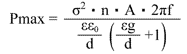
(σ はエレクトレットの表面電荷密度、n は極数すなわちエレクトレットの数、A(t)はエレクトレットと対向する導体の面積(時間の関数)、f は導体の往復運動の周波数、d はエレクトレットの厚み、g はエレクトレットと導体との距離、ε はエレクトレット材料の比誘電率である。)
上記式(1)より、より高い機械―電気変換特性が得られるエレクトレット10としては、表面電荷密度σが高く、厚みが厚く、比誘電率の小さい強誘電体であることが好ましい。
強誘電体において、表面電荷密度σは、残留分極値の大きさにより見積もることができる。従って、エレクトレット10は、大きな残留分極値を与えうる無機強誘電体を主成分とすることが好ましい。
大きな残留分極値を与えうる(強誘電性の優れた)無機強誘電体の結晶構造としては、結晶構造が、ペロブスカイト構造、ビスマス層状構造、タングステンブロンズ構造が挙げられ、中でもペロブスカイト構造が好ましい。
また、より大きな残留分極値を与えるためには、エレクトレット10は、強誘電体の分極軸の向きが略一様であり、且つ、その向きが厚み方向に対して平行に近いものであることが好ましい。本実施形態のエレクトレット10は結晶配向性を有している。従って、強誘電体の分極軸の向きが厚み方向に対して略平行に揃うように結晶配向性を制御した構成とすることにより、大きな残留分極値を与えるエレクトレット10とすることができる。かかる構成の場合、単結晶又はエピタキシャル膜であることがより好ましい。
強誘電性の優れたペロブスカイト型酸化物としては、鉛系ペロブスカイト型酸化物が知られているが、環境負荷の観点から、鉛を含まないペロブスカイト型酸化物を主成分とするものが好ましく、ビスマス含有ペロブスカイト型酸化物がより好ましい。
ペロブスカイト型酸化物の具体例としては、鉛系では、チタン酸鉛、チタン酸ジルコン酸鉛(PZT)、ジルコニウム酸鉛、チタン酸鉛ランタン、ジルコン酸チタン酸鉛ランタン、マグネシウムニオブ酸ジルコニウムチタン酸鉛、ニッケルニオブ酸ジルコニウムチタン酸鉛、亜鉛ニオブ酸ジルコニウムチタン酸鉛等の鉛含有化合物、及びこれらの混晶系;
非鉛系では、チタン酸バリウム(BTO)、チタン酸ストロンチウムバリウム、チタン酸ビスマスナトリウム、チタン酸ビスマスカリウム、ニオブ酸ナトリウム、ニオブ酸カリウム、ニオブ酸リチウム等、及びこれらの混晶系、BiFeO3(BFO)等下記一般式(PX)で表される組成を有するペロブスカイト型酸化物(不可避不純物を含んでもよい)等が挙げられる。
(Bix,A1-x)(By,C1-y)O3・・・(PX)
(式(PX)中、AはPb以外の平均イオン価数が2価のAサイト元素、Bは平均イオン価数が3価のBサイト元素,Cは平均イオン価数が3価より大きいBサイト元素であり、A,BおよびCは各々1種又は複数種の金属元素である。Oは酸素。B及びCは互いに異なる組成である。0.6≦x≦1.0、x-0.2≦y≦x。Aサイト元素の総モル数及びBサイト元素の総モル数の、酸素原子のモル数に対する比は、それぞれ1:3が標準であるが、ペロブスカイト構造を取り得る範囲内で1:3からずれてもよい。)
一方、残留分極値が高くても、比誘電率が大きくなるとその機械―電気変換効率は小さくなる。従って、エレクトレット10としては、強誘電性の優れる構成のうち、より比誘電率が小さくなるように組成設計された強誘電体とすることが好ましい。例えば、PZT等のペロブスカイト型酸化物においては、MPB近傍組成(Zr:Ti=52:48)をはずすことにより、残留分極値が10μC/cm2以上であり、且つ、比誘電率が400以下である強誘電体とすることができ、好ましい。
エレクトレット10の厚みdの好適な値は、静電誘導型変換素子の用途によって異なる。静電誘導型変換素子1の主な用途としては、発電素子や、マイクロフォン,圧力センサ,加速度センサ,地震計等のセンサ及びその応用素子が挙げられる。発電量を大きくする観点からは、上記したように、エレクトレット10の厚みは、厚い方が好ましい。用途に応じ、求められる発電量及び大きさを考慮し、エレクトレット10の厚みは設計されることが好ましい。本実施形態の静電誘導型変換素子は、機械―電気変換効率が高いため、従来のエレクトレット材料に比して、比較的薄い膜厚にて同等の発電量を達成することができる。
小型化の観点からは、エレクトレット10は、下部電極21上に形成された強誘電体膜であることが好ましい。強誘電体膜の成膜方法は特に制限されないが、分極処理をしなくても分極方向を略一様にすることが可能な気相成膜方法を用いることが好ましい。かかる成膜方法としては、プラズマを用いたスパッタ法が挙げられる。分極処理については以下に述べる。
上記したように、エレクトレット10は、表面10s付近に電荷が多数存在している。本実施形態において、エレクトレット10は結晶配向性を有する強誘電体である。従って、表面10付近に電荷を多数存在させるには、強誘電体を分極させればよい。分極処理を施すことにより、表面10s付近に電荷を多数存在させることができ、エレクトレット10とすることができる。
エレクトレット10の分極方法としては、特に制限されず、一般的な方法であるコロナ放電処理等を挙げることができる。脱分極による特性劣化を防止する観点からは、エレクトレット10を構成する強誘電体の抗電界値は高い方が好ましい。耐熱性について述べた箇所において、エレクトレット10を構成する強誘電体のキュリー温度は高い方が好ましいことを述べたが、脱分極による特性劣化の観点からも、キュリー温度は高い方が好ましい。
エレクトレット10として強誘電体膜を用いる構成においては、スパッタ法により成膜した強誘電体膜は、その膜の組成にもよるが、特段分極処理を施さずとも、分極軸の方向が自ずと略一様になった結晶配向性を有する強誘電体膜となる傾向がある。例えば、高い強誘電性を有するチタン酸ジルコン酸鉛(Pb(Zr,Ti)O3:PZT)は、スパッタ成膜後のas-depo状態において、自発分極軸が上向きに略一様に揃った膜(c軸配向膜<001>配向))となる。かかる成膜方法を用いることにより、分極処理を必要とせず、簡易なプロセスにて、高い表面電荷密度を有し、更に、誘電率の比較的小さいエレクトレット10を得ることができる。
強誘電体からなるエレクトレット10において、強誘電性の高い構成とすればするほど、自発分極の値が大きくなり、エレクトレット10の表面10sと対向電極22との間のギャップ空間に高い電界を生じる。ギャップ空間に電界の大きさがkV/mm以上となるような高電界が生じる場合は、対向電極22から放電を生じてエレクトレット10の表面10sが帯電することがある。その場合、エレクトレット10の表面10sに、表面帯電電荷を生じることになり、強誘電体の高い分極特性を有効に利用することができなくなる。従って、このような場合は、表面帯電電荷の除去処理を行うことが好ましい。
表面帯電電荷の除去処理としては、分極したエレクトレット10の表面10sを絶縁コート膜で覆う処理や、対向電極22とエレクトレット10sとの間のギャップ空間を真空化する処理や、絶縁ガスや絶縁流体を満たす処理等が挙げられる。
かかる絶縁コート膜としては、ポリテトラフルオロエチレン(PTFE)等のポリマー膜や、SiO2等の無機絶縁膜が挙げられる。また、絶縁ガスとしては、窒素ガス、六フッ化硫黄ガス等が挙げられ、絶縁流体としては、シリコンオイル等が挙げられる。
静電誘導型変換素子1は、以上のように構成されている。
静電誘導型変換素子1は、上記構成を有していればその製造方法は特に限定されない。下部電極20上への強誘電体(分極処理前のエレクトレット)10の形成方法としては、強誘電体10の態様によって適宜好適な方法を用いればよい。
例えば、強誘電体10がバルク体(単結晶又はセラミックス)の場合には、下部電極21の一主面に、強誘電体10を貼付すればよい。この際、強誘電体10の貼付面は研磨されて平坦化されているようにすることが好ましい。
また、強誘電体10が膜である場合には、上記したスパッタ法等の通常の薄膜形成技術により成膜することができる。薄膜形成技術によれば、比較的容易に配向制御が可能であり、スパッタ法による成膜における分極処理に関する利点は既に述べたとおりである。
一方、上述のように、静電誘導型変換素子1としては、強誘電体10の膜厚は厚い方がその発電量は大きくなるが、通常の薄膜形成技術によって可能な膜厚には限界がある。従って、強誘電体10を、例えば10μmを超えるような厚膜とする場合には、スクリーン印刷法やエアロゾルデポジション法(AD法)、水熱合成法等により成膜することが好ましい。
表1は、種々の強誘電体を用いてエレクトレット10を形成した場合の、静電誘導型発電素子の発電量を、表面電荷密度及び誘電率の値を上記式(1)に代入して見積もった値を示したものである。表1において、発電量は、式(1)において、d,n,A,f,g値を共通とし、フッ素系ポリマー(サイトップ(登録商標),旭硝子社製)からなるエレクトレット10として得られた発電量を基準値(1)とした場合の相対発電量として示してある。
また、表1の強誘電体の組成は、PZTセラミクス及びc-PZTはPb(Ti0.5,Zr0.5)O3,c-BFO-BTOは(Bi0.8,Ba0.2)(Fe0.8,Ti0.2)O3,BFO-BTOセラミクスは(Bi0.7,Ba0.3)(Fe0.7,Ti0.3)O3とした。c-との表記はc軸配向を意味する。
表1に示されるように、無配向のPZTセラミクスやBFO-BTOセラミクス,及びPVDF(ポリフッ化ビニリデン)についてはサイトップの発電量を大きく下回る発電量しか得られなかったが、各種c軸配向強誘電体膜及び強誘電体単結晶(3軸配向)については、サイトップに比して1桁から2桁程度大きい発電量が見積もられた。

静電誘導型変換素子1は、誘電分極体(エレクトレット)10として、結晶配向性を有する強誘電体からなる(不可避不純物を含んでもよい)エレクトレット材を用いている。かかる構成によれば、残留分極値の大きい強誘電体を、更に、配向させて誘電分極体とすることにより、非常に大きな表面電荷密度を有するのみならず、誘電率を減少させて、より大きな機械―電気変換特性(発電特性)を達成することができる。また、強誘電体として、ペロブスカイト型酸化物等の無機材料を用いた構成では、樹脂材料に比して高い耐熱性を有し、且つ、機械-電気変換効率の高い静電誘導型変換素子1とすることができる。
「設計変更」
本発明は上記実施の形態に限定されるものではなく、発明の要旨を変更しない限りにおいて、種々変更することが可能である。
例えば、静電誘導型変換素子の態様として、エレクトレット10が複数の細片状であり、下部電極21及び対向電極22もそれに対応した数備えられた構成としてもよい。かかる構成では、基板上に複数の下部電極21及びその表面にエレクトレット10が形成された態様とすればよい。
本発明の静電誘導型変換素子は、発電素子や、マイクロフォン,圧力センサ,加速度センサ,地震計等のセンサ及びその応用素子として好ましく利用できる。
Claims (10)
- 電気エネルギーと運動エネルギーとを変換する静電誘導型変換素子であって、
一主面が導体からなる基材と、
該主面上に形成された誘電分極体と、
該誘電分極体の前記主面と反対側の表面と対向配置され、前記表面との対向面積が変化するように前記誘電分極体と相対運動する電極とを備え、
前記誘電分極体が結晶配向性を有する強誘電体からなる(不可避不純物を含んでもよい)ことを特徴とする静電誘導型変換素子。 - 前記強誘電体の分極方向が略一様であることを特徴とする請求項1に記載の静電誘導型変換素子。
- 前記分極方向が、前記強誘電体の厚み方向であることを特徴とする請求項2に記載の静電誘導型変換素子。
- 前記強誘電体が、単結晶であることを特徴とする請求項1~3のいずれかに記載の静電誘導型変換素子。
- 前記強誘電体の厚み方向の残留分極値が10μC/cm2以上であり、比誘電率が400以下であることを特徴とする請求項1~4のいずれかに記載の静電誘導型変換素子。
- 前記電極が前記表面と平行な方向に相対運動することを特徴とする請求項1~5のいずれかに記載の静電誘導型変換素子。
- 前記強誘電体の結晶構造がペロブスカイト構造、ビスマス層状構造、タングステンブロンズ構造のいずれかであることを特徴とする請求項1~6のいずれかに記載の静電誘導型変換素子。
- 前記強誘電体が、鉛を含まないペロブスカイト型酸化物を主成分とすることを特徴とする請求項1~7に記載の静電誘導型変換素子。
- 前記強誘電体が、ビスマス含有ペロブスカイト型酸化物を主成分とすることを特徴とする請求項8に記載の静電誘導型変換素子。
- 前記強誘電体が、前記基材上に成膜された強誘電体膜であることを特徴とする請求項1~9のいずれかに記載の静電誘導型変換素子。
Applications Claiming Priority (2)
| Application Number | Priority Date | Filing Date | Title |
|---|---|---|---|
| JP2010-269990 | 2010-12-03 | ||
| JP2010269990A JP5702125B2 (ja) | 2010-12-03 | 2010-12-03 | 静電誘導型変換素子 |
Publications (1)
| Publication Number | Publication Date |
|---|---|
| WO2012073465A1 true WO2012073465A1 (ja) | 2012-06-07 |
Family
ID=46171439
Family Applications (1)
| Application Number | Title | Priority Date | Filing Date |
|---|---|---|---|
| PCT/JP2011/006569 Ceased WO2012073465A1 (ja) | 2010-12-03 | 2011-11-25 | 静電誘導型変換素子 |
Country Status (2)
| Country | Link |
|---|---|
| JP (1) | JP5702125B2 (ja) |
| WO (1) | WO2012073465A1 (ja) |
Cited By (4)
| Publication number | Priority date | Publication date | Assignee | Title |
|---|---|---|---|---|
| JP2017518512A (ja) * | 2014-04-18 | 2017-07-06 | 北京納米能源与系統研究所 | 静電誘起によるセンサ、発電機、センシング方法及び発電方法 |
| JP2018088778A (ja) * | 2016-11-29 | 2018-06-07 | 国立大学法人 東京大学 | 振動発電デバイス |
| JP2021097083A (ja) * | 2019-12-13 | 2021-06-24 | 株式会社デンソー | エレクトレット |
| US11558694B2 (en) | 2019-12-13 | 2023-01-17 | Denso Corporation | Electret |
Families Citing this family (3)
| Publication number | Priority date | Publication date | Assignee | Title |
|---|---|---|---|---|
| JP6232047B2 (ja) | 2013-03-19 | 2017-11-22 | 仙台スマートマシーンズ株式会社 | 静電誘導型の振動発電装置及びその製造方法 |
| JP7297280B2 (ja) * | 2018-08-29 | 2023-06-26 | 国立大学法人千葉大学 | 振動発電器及びエレクトレット |
| JP2022038899A (ja) * | 2020-08-27 | 2022-03-10 | 国立大学法人東北大学 | 発電素子 |
Citations (6)
| Publication number | Priority date | Publication date | Assignee | Title |
|---|---|---|---|---|
| JPH02219478A (ja) * | 1989-02-17 | 1990-09-03 | Seiko Epson Corp | エレクトレット発電機 |
| JPH08264020A (ja) * | 1995-03-27 | 1996-10-11 | Tokuyama Corp | 強誘電性材料 |
| JP2003146660A (ja) * | 2001-11-13 | 2003-05-21 | Fuji Electric Co Ltd | 強誘電体および誘電体薄膜コンデンサ、圧電素子 |
| JP2005144594A (ja) * | 2003-11-14 | 2005-06-09 | Ricoh Co Ltd | アクチュエータ装置、アクチュエータ、液滴吐出装置、液滴吐出ヘッド |
| JP2009224740A (ja) * | 2008-03-19 | 2009-10-01 | Fujifilm Corp | 積層構造体とそれを用いたデバイス、デバイスの製造方法,液体吐出装置 |
| JP2010175475A (ja) * | 2009-01-30 | 2010-08-12 | Sumitomo Electric Ind Ltd | 車輪速センサ及び車載センサ |
-
2010
- 2010-12-03 JP JP2010269990A patent/JP5702125B2/ja not_active Expired - Fee Related
-
2011
- 2011-11-25 WO PCT/JP2011/006569 patent/WO2012073465A1/ja not_active Ceased
Patent Citations (6)
| Publication number | Priority date | Publication date | Assignee | Title |
|---|---|---|---|---|
| JPH02219478A (ja) * | 1989-02-17 | 1990-09-03 | Seiko Epson Corp | エレクトレット発電機 |
| JPH08264020A (ja) * | 1995-03-27 | 1996-10-11 | Tokuyama Corp | 強誘電性材料 |
| JP2003146660A (ja) * | 2001-11-13 | 2003-05-21 | Fuji Electric Co Ltd | 強誘電体および誘電体薄膜コンデンサ、圧電素子 |
| JP2005144594A (ja) * | 2003-11-14 | 2005-06-09 | Ricoh Co Ltd | アクチュエータ装置、アクチュエータ、液滴吐出装置、液滴吐出ヘッド |
| JP2009224740A (ja) * | 2008-03-19 | 2009-10-01 | Fujifilm Corp | 積層構造体とそれを用いたデバイス、デバイスの製造方法,液体吐出装置 |
| JP2010175475A (ja) * | 2009-01-30 | 2010-08-12 | Sumitomo Electric Ind Ltd | 車輪速センサ及び車載センサ |
Cited By (9)
| Publication number | Priority date | Publication date | Assignee | Title |
|---|---|---|---|---|
| JP2017518512A (ja) * | 2014-04-18 | 2017-07-06 | 北京納米能源与系統研究所 | 静電誘起によるセンサ、発電機、センシング方法及び発電方法 |
| JP2018088778A (ja) * | 2016-11-29 | 2018-06-07 | 国立大学法人 東京大学 | 振動発電デバイス |
| CN110050409A (zh) * | 2016-11-29 | 2019-07-23 | 国立大学法人东京大学 | 振动发电装置 |
| CN110050409B (zh) * | 2016-11-29 | 2020-08-25 | 国立大学法人东京大学 | 振动发电装置 |
| US11081977B2 (en) | 2016-11-29 | 2021-08-03 | The University Of Tokyo | Vibrational energy harvester device |
| JP2021097083A (ja) * | 2019-12-13 | 2021-06-24 | 株式会社デンソー | エレクトレット |
| US11558694B2 (en) | 2019-12-13 | 2023-01-17 | Denso Corporation | Electret |
| JP7426647B2 (ja) | 2019-12-13 | 2024-02-02 | 株式会社デンソー | エレクトレット |
| US11915883B2 (en) | 2019-12-13 | 2024-02-27 | Denso Corporation | Electret |
Also Published As
| Publication number | Publication date |
|---|---|
| JP2012120388A (ja) | 2012-06-21 |
| JP5702125B2 (ja) | 2015-04-15 |
Similar Documents
| Publication | Publication Date | Title |
|---|---|---|
| JP5702125B2 (ja) | 静電誘導型変換素子 | |
| JP5864168B2 (ja) | 圧電材料、圧電素子、液体吐出ヘッド、超音波モータおよび塵埃除去装置 | |
| Niu et al. | Integration-friendly, chemically stoichiometric BiFeO3 films with a piezoelectric performance challenging that of PZT | |
| Choi et al. | Preparation and characterization of piezoelectric ceramic–polymer composite thick films by aerosol deposition for sensor application | |
| WO2012105187A1 (ja) | 静電容量変化型発電素子 | |
| CN112993143B (zh) | 驻极体 | |
| CN101981718A (zh) | 压电薄膜及其制造方法、角速度传感器、利用角速度传感器进行的角速度的测定方法、压电发电元件及使用压电发电元件的发电方法 | |
| US9780295B2 (en) | Lead-free piezoelectric material | |
| CN102640315B (zh) | 压电体膜、喷墨头、使用喷墨头形成图像的方法、角速度传感器、使用角速度传感器测定角速度的方法、压电发电元件以及使用压电发电元件的发电方法 | |
| US9620703B2 (en) | Piezoelectric thin-film element, piezoelectric sensor and vibration generator | |
| CN102844901B (zh) | 压电体膜、喷墨头、使用喷墨头形成图像的方法、角速度传感器、使用角速度传感器测定角速度的方法、压电发电元件以及使用压电发电元件的发电方法 | |
| CN102844900B (zh) | 喷墨头、使用喷墨头形成图像的方法、角速度传感器、使用角速度传感器测定角速度的方法、压电发电元件以及使用压电发电元件的发电方法 | |
| WO2024070849A1 (ja) | 無鉛圧電組成物、及び圧電素子 | |
| TW202505987A (zh) | 壓電積層體、壓電積層體的製造方法、及壓電元件 | |
| CN102859736B (zh) | 压电体膜、喷墨头、使用喷墨头形成图像的方法、角速度传感器、使用角速度传感器测定角速度的方法、压电发电元件以及使用压电发电元件的发电方法 | |
| JP5869439B2 (ja) | ウルツァイト型複合酸化物及びそれを備えた圧電素子 | |
| JP7707434B2 (ja) | 無鉛圧電組成物、及び圧電素子 | |
| JP2021097212A (ja) | エレクトレット | |
| KR101188331B1 (ko) | 압전 소자 | |
| JP7558290B2 (ja) | 圧電膜付き基板及び圧電素子 | |
| JP2021158206A (ja) | 圧電薄膜、圧電薄膜素子及び圧電トランデューサ | |
| US12464950B2 (en) | Electromechanical responsive film, stacked arrangement and methods of forming the same | |
| Kumar et al. | Nanocrystalline PNS-PZT-based energy harvester for strategic applications | |
| TW202439963A (zh) | 壓電積層體、壓電積層體的製造方法、及壓電元件 | |
| JP2025021632A (ja) | 無鉛圧電組成物、及び圧電素子 |
Legal Events
| Date | Code | Title | Description |
|---|---|---|---|
| 121 | Ep: the epo has been informed by wipo that ep was designated in this application |
Ref document number: 11844242 Country of ref document: EP Kind code of ref document: A1 |
|
| NENP | Non-entry into the national phase |
Ref country code: DE |
|
| 122 | Ep: pct application non-entry in european phase |
Ref document number: 11844242 Country of ref document: EP Kind code of ref document: A1 |