WO2012063633A1 - 露光方法及び露光位置の確認方法 - Google Patents
露光方法及び露光位置の確認方法 Download PDFInfo
- Publication number
- WO2012063633A1 WO2012063633A1 PCT/JP2011/074456 JP2011074456W WO2012063633A1 WO 2012063633 A1 WO2012063633 A1 WO 2012063633A1 JP 2011074456 W JP2011074456 W JP 2011074456W WO 2012063633 A1 WO2012063633 A1 WO 2012063633A1
- Authority
- WO
- WIPO (PCT)
- Prior art keywords
- exposure
- mask
- region
- light
- photochromic
- Prior art date
- Legal status (The legal status is an assumption and is not a legal conclusion. Google has not performed a legal analysis and makes no representation as to the accuracy of the status listed.)
- Ceased
Links
Images







Classifications
-
- G—PHYSICS
- G03—PHOTOGRAPHY; CINEMATOGRAPHY; ANALOGOUS TECHNIQUES USING WAVES OTHER THAN OPTICAL WAVES; ELECTROGRAPHY; HOLOGRAPHY
- G03F—PHOTOMECHANICAL PRODUCTION OF TEXTURED OR PATTERNED SURFACES, e.g. FOR PRINTING, FOR PROCESSING OF SEMICONDUCTOR DEVICES; MATERIALS THEREFOR; ORIGINALS THEREFOR; APPARATUS SPECIALLY ADAPTED THEREFOR
- G03F9/00—Registration or positioning of originals, masks, frames, photographic sheets or textured or patterned surfaces, e.g. automatically
-
- G—PHYSICS
- G03—PHOTOGRAPHY; CINEMATOGRAPHY; ANALOGOUS TECHNIQUES USING WAVES OTHER THAN OPTICAL WAVES; ELECTROGRAPHY; HOLOGRAPHY
- G03F—PHOTOMECHANICAL PRODUCTION OF TEXTURED OR PATTERNED SURFACES, e.g. FOR PRINTING, FOR PROCESSING OF SEMICONDUCTOR DEVICES; MATERIALS THEREFOR; ORIGINALS THEREFOR; APPARATUS SPECIALLY ADAPTED THEREFOR
- G03F7/00—Photomechanical, e.g. photolithographic, production of textured or patterned surfaces, e.g. printing surfaces; Materials therefor, e.g. comprising photoresists; Apparatus specially adapted therefor
- G03F7/20—Exposure; Apparatus therefor
-
- G—PHYSICS
- G03—PHOTOGRAPHY; CINEMATOGRAPHY; ANALOGOUS TECHNIQUES USING WAVES OTHER THAN OPTICAL WAVES; ELECTROGRAPHY; HOLOGRAPHY
- G03F—PHOTOMECHANICAL PRODUCTION OF TEXTURED OR PATTERNED SURFACES, e.g. FOR PRINTING, FOR PROCESSING OF SEMICONDUCTOR DEVICES; MATERIALS THEREFOR; ORIGINALS THEREFOR; APPARATUS SPECIALLY ADAPTED THEREFOR
- G03F7/00—Photomechanical, e.g. photolithographic, production of textured or patterned surfaces, e.g. printing surfaces; Materials therefor, e.g. comprising photoresists; Apparatus specially adapted therefor
- G03F7/70—Microphotolithographic exposure; Apparatus therefor
- G03F7/70691—Handling of masks or workpieces
- G03F7/70791—Large workpieces, e.g. glass substrates for flat panel displays or solar panels
Definitions
- the present invention relates to an exposure method such as a glass substrate and a polarizing film used in a display device such as a liquid crystal display and a method for confirming an exposure position.
- the present invention relates to an exposure method for easily confirming an exposure position and a method for confirming an exposure position when exposing the exposure pattern forming region simultaneously or successively.
- an exposure target member such as a glass substrate or film on which a material film such as an alignment material film is formed on the surface is exposed.
- photo-alignment is performed in a predetermined direction.
- the exposure light emitted from the exposure light source through a predetermined optical system is irradiated through the pattern of the light transmission region of the mask.
- the exposure target member is a glass substrate, for example, glass
- the substrate is placed on a movable stage, and is transported to the exposure light irradiation region by moving the stage. Then, the alignment material film formed on the glass substrate is photo-aligned by exposure corresponding to the mask pattern to form a predetermined exposure region.
- the exposure target member is a flexible member such as a film
- exposure by a roll-to-roll method as shown in FIG. 6 is performed, for example. That is, as shown in FIG.
- the film to be exposed is wound and conveyed in a roll shape between each process until the film is processed into a film as a product.
- a film roll is coaxially attached to the supply-side roller 80, and the film is sequentially wound from the leading end by the winding-side roller 81.
- the exposure apparatus 10 is passed through, for example, exposure light is applied to the alignment material film formed on the surface of the film. Continuous irradiation is performed to expose a predetermined exposure area of the film along the moving direction of the film.
- the film is stretched around, for example, a transport roller 9 and is transported between the devices by the rotation of the transport roller.
- an exposure target member 2 such as a glass substrate or a polarizing film used in this display device.
- an alignment film for example, a region corresponding to one pixel or one picture element is divided into, for example, two in the width direction, and an alignment film having a different alignment direction is formed for each divided region. Accordingly, display light having two types of pretilt angles can be transmitted in an area corresponding to the same pixel or picture element, and the viewing angle of the display device can be widened. It can be used as display light for the right eye and left eye. In this way, an exposure apparatus that divides an exposure target region and aligns the alignment films formed in different directions is called an alignment division method.
- FIG. 7 shows, as an example, a conventional exposure apparatus of a type in which exposure light sources 11 that emit exposure light are arranged to face each other corresponding to one mask 12 and irradiate exposure light from different directions.
- FIG. 7 shows, as an example, a conventional exposure apparatus of a type in which exposure light sources 11 that emit exposure light are arranged to face each other corresponding to one mask 12 and irradiate exposure light from different directions.
- the alignment division type exposure apparatus one alignment region is divided, and the alignment material film is aligned in different directions by irradiating each division region with exposure light from different directions. Can do.
- FIG. 8A is a view showing, as an example, the arrangement of exposure target members and masks when a conventional alignment division type exposure apparatus is used
- FIG. 8B is a mask used in this alignment division type exposure apparatus. It is a figure which shows as an example.
- a plurality of glass substrates or polarizing films are manufactured from one exposure target member 2, and a plurality of (for example, 3 rows ⁇ 3 columns) are formed on the substrate.
- An alignment material film 21 is formed in the exposure pattern formation region.
- the mask 12 is provided in such a size as to cover a region to be a plurality of (for example, 2 rows ⁇ 3 columns) glass substrates or polarizing films. As shown in FIG.
- the pattern forming portion 125 of the mask 12 is provided with a plurality of light transmission region patterns 125a extending in one direction in parallel with each other. A region corresponding to a plurality of glass substrates or polarizing films is exposed simultaneously. Each pattern 125a is formed to be spaced from each other at intervals corresponding to pixels or picture elements, and each pattern 125a is formed to have a width corresponding to half of one pixel or half of one pixel. Yes. As shown in FIG. 8A, in this exposure apparatus, after exposing a region of one pixel or half of one picture element, irradiation of exposure light is temporarily stopped, and an unexposed portion of the exposure target member 2 is exposed.
- alignment films 21a having different alignment directions can be formed so as to be adjacent to each other (FIG. 9A).
- the oblique lines in the alignment film 21a indicate the alignment directions of the alignment film 21a.
- FIG. 11A is a view showing the arrangement of exposure target members and masks when another alignment division type exposure apparatus is used.
- this exposure apparatus two masks 12 are provided for each region to be a glass substrate or a polarizing film. That is, as shown in FIG. 11A, each mask 12 is provided with a size that covers a region that becomes one glass substrate or a polarizing film in the column direction.
- a plurality of mask patterns 125a are formed with a width corresponding to half of one pixel or half of one picture element, and are separated from each other at intervals corresponding to one pixel or one picture element.
- the mask 12 is arranged so that the pattern formed by one mask 121 is adjacent to the pattern formed by the other mask 122, and is different from the exposure light source 11 provided corresponding to each mask 12.
- the exposure light having an angle is emitted, and the exposure light is transmitted through the respective masks 12 from different directions.
- the exposure target member 2 is continuously supplied to the irradiation region of the exposure light and continuously exposed to form a pattern in a strip shape along the moving direction of the exposure target member 2.
- alignment films 21a having different alignment directions can be formed adjacent to each other (FIG. 11B).
- FIG. 12 is a diagram showing the arrangement of exposure target members and masks when still another orientation division type exposure apparatus is used. Also in this exposure apparatus, the exposure target member 2 is continuously supplied into the exposure apparatus. Two masks 12 are arranged on each of the upstream side and the downstream side in the moving direction of the exposure target member 2. As described above, the arrangement in which a plurality of masks 12 are arranged on the upstream side and the downstream side in the moving direction of the exposure target member 2 cannot make the size of the mask 12 larger than the area to be a glass substrate or a polarizing film. This is suitable when the exposure target member 2 is a member such as a film that undulates during conveyance.
- FIG. 13 shows a modification of the exposure apparatus shown in FIG.
- masks 121 and 122 and masks 123 and 124 are arranged on the upstream side and the downstream side in the moving direction of the exposure target member 2, respectively, and are arranged apart from each other.
- the film 2 is exposed in the exposure areas A and C with the upstream masks 121 and 122, and the area B between the exposure areas A and C is exposed with the mask 123 on the downstream side, and the area D adjacent to the exposure area C Is exposed by a mask 124.
- segmentation can be accurately formed in the substantially whole surface of the area
- the alignment film 21a is formed by exposure at most twice (in the case of step exposure as shown in FIG. 8) in an area that becomes a glass substrate or a polarizing film for a single display device.
- Patent Document 1 discloses a technique in which exposure is performed while shifting one mask 12 on which a periodic pattern is formed by shifting the pattern interval, and the exposure light is divided several times by dividing the irradiation energy. It is disclosed that the joint formed at the boundary between adjacent patterns can be made inconspicuous by irradiation.
- Patent Document 1 In the technique of Patent Document 1, it is necessary to perform exposure at least as many times as the number of patterns on one exposure target member 2, and productivity is extremely low.
- the exposure target member 2 and the alignment film are usually formed of a material having a very high light transmittance, for example, due to a shift of the mask position, FIG. 9B, FIG. 11C, and FIG. As shown in FIG. 12 (c), it is difficult to visually recognize when the adjacent exposure regions are overlapped and exposed and when an unexposed portion remains. Therefore, it is not possible to confirm the overlap of the exposed areas or the presence or absence of the unexposed areas until the glass substrate or the polarizing film is assembled into a liquid crystal display to be modularized and the liquid crystal is actually driven. In addition, when there is a poorly exposed region, there is a problem that the entire modularized display device is wasted.
- the present invention has been made in view of such problems, and when exposing an exposure pattern forming region in a plurality of times, or when exposing a plurality of exposure pattern forming regions simultaneously or continuously, It is an object of the present invention to provide an exposure method and an exposure position confirmation method in which the exposure position can be easily confirmed.
- An exposure method irradiates an exposure target member having an exposure pattern formation region and at least a part of a non-pattern formation region around the exposure pattern formation region through a mask.
- a photochromic material that changes color by irradiation of the exposure light is applied to an area on the extension of the exposure pattern in the non-pattern formation region
- a photochromic member that changes color by irradiation of the exposure light and when irradiating the exposure target member with the exposure light transmitted through the mask, in addition to the exposure pattern forming region, the light It is characterized by irradiating the color-changing material or the light-coloring member to change the color.
- the degree of color change of the photochromic material or the photochromic member varies depending on, for example, the number of exposure light irradiations and / or the irradiation time.
- a plurality of the exposure pattern forming areas are formed on the exposure target member, and the non-pattern forming areas are formed between the exposure pattern forming areas.
- the photochromic material or the photochromic member is applied to a non-pattern forming region between the exposure pattern forming regions to be exposed.
- the photochromic material or the photochromic member is applied to a non-pattern forming region between the pattern forming regions arranged in the moving direction of the exposure target member.
- the method for confirming the exposure position according to the present invention is a method for confirming the exposure position in the exposure target member exposed by the above-described exposure method, wherein the photochromic material or the photochromic member changed in color by irradiation with the exposure light.
- the exposure position in the exposure pattern formation region is confirmed by the color change.
- the exposure method according to the present invention uses an exposure target member having an exposure pattern formation region and a non-pattern formation region in at least a part of its periphery, and extends the exposure pattern in the non-pattern formation region of the exposure target member.
- a photochromic material that changes color by irradiation of exposure light is applied to a certain area, or a photochromic member that changes color by irradiation of exposure light is applied, and the exposure light transmitted through the mask is irradiated to the exposure target member.
- the photochromic material or photochromic member is also irradiated to change the color. Therefore, the exposure position in the exposure pattern forming region can be easily confirmed by the color change of the photochromic material or the photochromic member.
- the exposure position confirmation method according to the present invention is easy to confirm the exposure position.
- the overlapping of exposure positions can be achieved without actually assembling a glass substrate or a polarizing film on a display device such as a liquid crystal display and actually driving the liquid crystal.
- a display device such as a liquid crystal display and actually driving the liquid crystal.
- the presence or absence of exposure failure such as an unexposed area can be confirmed, and the display device is not wasted.
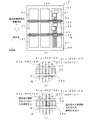
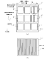
- FIG. 1 is a diagram showing an exposure method according to the first embodiment of the present invention
- (b) is an enlarged view of part A in FIG. 1 (a)
- (c) is a case where overlapping exposure positions and unexposed areas occur.
- FIG. It is a figure which shows a mask as an example. It is a figure which shows as an example the control apparatus which controls the position of an alignment mark formation part, and a mask position.
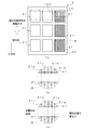
- (A) is a diagram showing an exposure method according to the second embodiment of the present invention, (b) is an enlarged view of part B of FIG. 4 (a), and (c) is a case where overlapping exposure positions and unexposed areas occur.
- FIG. 1 In the exposure apparatus which concerns on 2nd Embodiment of this invention, it is a figure which shows correction
- (A) is a figure which shows as an example the arrangement
- FIG. 4C is a schematic diagram showing an alignment film when an overlap of exposure positions and an unexposed area occur.
- FIG. 4C is a schematic diagram showing an alignment film when an overlap of exposure positions and an unexposed area occur. It is a figure which shows the modification of the exposure apparatus of FIG.
- FIG. 1A is a view showing an exposure method according to the first embodiment of the present invention
- FIG. 1B is an enlarged view of a portion A in FIG. 1A
- FIG. It is the A section enlarged view which shows the case where an exposure area
- FIG. 2 is a diagram showing an example of a mask in the present embodiment. As shown in FIG.
- an alignment material film 21 is formed in an exposure pattern forming region of 3 rows ⁇ 3 columns on the surface of the exposure target member 2, and the mask 12 is
- the light transmitting region pattern 125a of the mask 12 is provided in a size that covers the region where the alignment material film 21 of 2 rows ⁇ 3 columns is formed, and a plurality of patterns 125a extend in the row direction of the exposure pattern formation region.
- the books are formed so as to be parallel to each other. Then, the alignment material film 21 of 2 rows ⁇ 3 columns is simultaneously exposed by the mask 12.
- a photochromic material that changes color by irradiation of exposure light is applied to an area on the extension of an exposure pattern in a non-pattern formation area, or a photochromic member that changes color by irradiation of exposure light is attached to light.
- the light changing region 22 is also irradiated to change the color.
- the photochromic region 22 is formed in a non-pattern forming region between rows of the alignment material film 21 arranged in three columns.
- the photochromic region 22 is formed in a region between the alignment material films 21 that are simultaneously exposed by at least one pattern 125a, and the color is changed by irradiation of the exposure light transmitted through the pattern 125a to confirm the exposure position.
- FIG. 1A shows the case where the alignment film 21a is formed only in the region of one pixel or one pixel in the column direction among the exposure regions exposed by the mask 12.
- the exposure light source 11 that emits exposure light, the mask 12, and the exposure light emitted from the exposure light source 11 are masked 12 as in the conventional exposure apparatus shown in FIGS.
- the exposure light emitted from is irradiated to the exposure target member 2 of the glass substrate or film on which the alignment material film 21 is formed through the mask 12, and the alignment material film 21 is photo-aligned corresponding to the mask pattern.
- the alignment film 21a is formed.
- the glass substrate is placed on a movable transfer device such as a transfer stage and transferred, and the alignment material film 21 in the pattern formation region is arranged at the exposure light irradiation position. In the exposure, the conveyance is stopped.
- the exposure target member is a film
- the film 2 supplied from the supply-side roller 80 is wound while maintaining the tension state of the film by the take-up roller 81 by the roll-to-roll method, as in the conventional case.
- the alignment material film 21 in the pattern formation region is formed at the exposure light irradiation position, and the conveyance is stopped during the exposure.
- one or more film transport rollers 9 are disposed between the two rollers 80 and 81, and each of the transport rollers 9 is driven by a motor, for example. .
- a motor for example.
- the configuration is the same as that of the present embodiment except for the configuration of the transport device.
- the exposure light source 11 is a light source that emits ultraviolet light, for example, a mercury lamp, a xenon lamp, an excimer lamp, an ultraviolet LED, or the like, and a light source that emits continuous light or pulsed laser light is used.
- an optical system such as a collimator lens and / or a reflecting mirror is disposed on the optical path of the exposure light emitted from the exposure light source 11, for example, exposure pattern formation on the glass substrate 20 to be exposed.
- the alignment material film 21 formed in the use region is configured to be irradiated with exposure light with a predetermined light amount.
- the exposure light source 11 can adjust the emission direction of the exposure light by, for example, a control device (not shown), and can thereby adjust the incident angle of the exposure light with respect to the exposure target member 2.
- the mask 12 includes, for example, a frame 120 and a pattern forming portion 125 at the center thereof, and a pattern 125 a of a predetermined light transmission region is formed in the pattern forming portion 125. That is, in the pattern forming portion 125, an opening that transmits exposure light is formed corresponding to the pattern shape formed on the film 2, or a light transmissive member is installed.
- This pattern 125a is composed of a plurality of light transmission regions extending in the row direction of the exposure pattern forming region, for example, as in the conventional mask, and each pattern 125a is mutually spaced at intervals corresponding to pixels or picture elements.
- the patterns 125a are spaced apart from each other and have a width corresponding to half the width of one pixel or half of one picture element. Then, the mask pattern is exposed to the alignment material film 21 on the surface of the exposure target member 2 by the transmitted light of the pattern 125a. As described above, in this embodiment, the alignment material film 21 of 2 rows ⁇ 3 columns is simultaneously exposed by one mask 12.
- the mask 12 is provided with a viewing window 12a for a line CCD having a width of about 300 ⁇ m and a length of about 250 mm at a position different from the pattern 125a, and the longitudinal direction of the viewing window 12a.
- a linear light shielding pattern 12b having a width of, for example, about 15 ⁇ m is provided in the middle of the light.
- a line CCD 15 for detecting the mask position is provided under the mask 12.
- the position of the light shielding pattern 12b can be detected by the line CCD 15 and used for position adjustment of the mask 12.
- the positions and shapes of the viewing window 12a and the light shielding pattern 12b in the present embodiment are examples, and the present invention is not limited by these positions and shapes.
- a plurality of slits that intersect with each other may be provided instead of the light shielding pattern 12b. Further, as long as the position adjustment of the mask 12 can be performed with high accuracy, these configurations may not be provided.
- the mask 12 is configured such that, for example, a portion of the frame 120 is supported by a mask stage 17 (see FIG. 7), and the entire mask 12 can be moved by the movement of the mask stage 17.
- the mask stage 17 is connected to a control device 30 as shown in FIG. 3, for example, and the position thereof is controlled, for example, in the horizontal direction (row direction of the glass substrate 20 or row direction of the glass substrate 20) under the control of the control device 30. And in the row direction). Thereby, the exposure position of the alignment material film 21 by the mask 12 can be adjusted in the horizontal direction.
- the mask stage 17 is movable in the vertical direction, for example, and is configured to be adjusted so that the alignment material film 21 on the glass substrate 20 is exposed with a predetermined size.
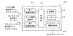
- FIG. 3 shows an example of the configuration of the control device 30 that controls the mask position.
- the control device 30 is connected to, for example, a mask stage driving unit and a motor control unit provided on a roller 81 on the film winding side.
- the control device 30 detects the position of the first image processing unit 31 connected to the mask CCD 15 for detecting the mask position provided below the mask 12 and the alignment mark 2a described later in the modification of the second embodiment.
- a second image processing unit 32 connected to the line CCD 14, a motor drive control unit 33, a calculation unit 34, a memory 35, a mask stage drive control unit 36, and a control unit 37 are provided.
- the first image processing unit 31 performs image processing of the light shielding pattern 12b of the mask 12 picked up by the mask CCD for detecting the mask position, and detects the position of the light shielding pattern 12b in the column direction of the exposure pattern forming area.
- the second image processing unit 32 performs image processing of the alignment mark 2a picked up by the alignment mark detection line CCD 14, and detects the position of the alignment mark 2a in the column direction of the exposure pattern forming region.
- the motor drive control unit 33 controls the rotation speed when the motor of the roll 81 on the winding side is driven or stopped, or is driven.
- the calculation unit 34 calculates the displacement or meandering amount of each detection target based on the mask position detected by each line CCD, or the mask position and the position of the alignment mark 2a. That is, the calculation unit 34 calculates the deviation from the position where the mask 12 should be set, based on the detection result of the first image processing unit 31.
- the calculation unit 34 determines the relative value between the two to be set based on the detection results of the first image processing unit 31 and the second image processing unit 32. The deviation from the distance to be set is calculated based on the positional relationship and the actual relative positional relationship between the two.
- the memory 35 stores the detection results of the first image processing unit 31 and the second image processing unit 32 and the calculation result of the calculation unit 34.
- the mask stage drive control unit 36 controls the drive of the mask stage 17, and can adjust the mask position by controlling the movement direction and the movement amount of the mask stage 17, for example.
- the control unit 37 controls the first and second image processing units 31 and 32, the motor drive control unit 33, the calculation unit 34, the memory 35, and the mask stage drive control unit 36.
- the exposure apparatus 1 adjusts the position of the mask 12, for example, in the column direction of the exposure pattern formation region, or the motor provided on the roller 81 on the take-up side when the exposure target member 2 is a film. It is comprised so that rotation speed etc. of this can be controlled.
- the glass substrate 20 to be exposed is supplied to, for example, the slit coater 4 before being supplied to the exposure apparatus 10, and the slit coater 4 has a photo-alignment property in a predetermined region on the surface of the glass substrate 20.
- the material is applied in the form of a film.
- the glass substrate 20 to which the material is applied is supplied to, for example, the drying device 5, and the photo-alignment material is dried or baked by the drying device 5. Thereby, an alignment material film 21 is formed in a predetermined region on the surface of the glass substrate 20.
- the slit coater 4 is configured such that the photochromic region 22 can be formed by applying a photochromic material to the non-pattern forming region between the rows of the alignment material films 21 arranged in three columns, for example. Yes.
- the photochromic material is applied by another application device different from the slit coater 4 that applies the photo-alignment material.
- the photochromic region 22 is formed by pasting a photochromic member that changes color by exposure light exposure, the photochromic member is pasted by, for example, a pasting device before being supplied to the exposure apparatus.
- a photochromic material constituting the photochromic region 22 for example, a general photochromic material can be used. Examples of the photochromic material include azobenzene and diarylethene. Then, a liquid or paste-like material containing these components is applied to the non-pattern forming region between the alignment material films.
- a photochromic region 22 is formed of a photochromic member, a tape or sheet-like member such as a UV label that changes color by irradiation with exposure light such as ultraviolet light can be used as the photochromic member.
- a tape or sheet-like member such as a UV label that changes color by irradiation with exposure light such as ultraviolet light can be used as the photochromic member.
- the non-pattern forming region by forming the photo-discoloring region 22 that changes color by exposure light exposure, an unexposed region in the pattern forming region can be confirmed.
- the photochromic region 22 is formed in a region between the alignment material films 21 that are simultaneously exposed by at least one pattern 125a, and therefore corresponds to a region where the photochromic region 22 is not discolored. It can be determined that the alignment material film 21 in the pattern forming region to be unexposed.
- the photochromic material and the photochromic member it is preferable to use materials having different degrees of discoloration depending on the number of exposure light irradiations and / or the irradiation time. That is, when exposure light is irradiated to the photochromic region 22 a plurality of times, it can be visually recognized that the degree of color change is different, so that the overlapping of exposure positions, the number of exposures, and the like can be determined.
- the operation of the exposure apparatus of this embodiment will be described.
- an alignment material film 21 is formed, and a photochromic material that becomes the photochromic region 22 is applied, or a photochromic member is formed. Affixed. That is, the glass substrate 20 is supplied to the slit coater 4 in a state where no exposure material film is applied on the surface, and a material to be the alignment material film 21 is applied by the slit coater 4.
- the slit coater 4 applies the material to be the alignment material film 21 in three rows in the row direction by conveying the glass substrate 20, and intermittently repeats this three times to thereby apply the material application region. Are formed in three rows in the row direction.
- the slit coater 4 is configured to be able to apply a liquid or paste-like photochromic material
- the slit coater 4 is provided with a photochromic material in a non-pattern forming region between rows of alignment film materials arranged in three columns. Also apply.
- the coating device for the photochromic material is provided separately from the slit coater 4, the coating device is used to coat the photochromic material in the non-pattern forming region between the rows of the alignment film materials arranged in three columns. . Thereby, a liquid or paste-like alignment film material and a photochromic material are applied to the surface of the glass substrate 20.
- the glass substrate 20 coated with a predetermined exposure material is transported to the drying device 5, and the liquid or paste-like exposure material on the surface is dried. Thereby, an alignment material film 21 and a photochromic region 22 made of a photochromic material are formed on the surface of the glass substrate 20. That is, on the glass substrate 20, an exposure pattern forming region made of the alignment material film 21 is formed in 3 rows ⁇ 3 columns, and in the non-pattern forming region between the rows of the alignment material films 21 arranged in 3 columns, the photochromic color is changed. A photochromic region 22 made of a material is formed.
- the photochromic material may be applied after the alignment film material is dried by the drying device 5 when the photochromic material does not need to be dried and when the photochromic property changes due to drying.
- the photochromic region 22 is formed by a photochromic member that changes color by irradiation with exposure light
- a tape or sheet-like UV is formed in the non-pattern forming region between the alignment film material rows before being supplied to the exposure apparatus. Affix a member such as a label.
- the glass substrate 20 on the surface of which the exposure pattern forming region composed of the alignment material film 21 of 3 rows ⁇ 3 columns and the photochromic region 22 between the rows is formed is placed on a transport device such as a transport stage, for example. It is supplied into the exposure apparatus 1.
- the glass substrate 20 is disposed below the mask 12 by the conveyance by the conveyance device.
- the mask 12 is formed to have a size covering a region where the alignment material film 21 of 2 rows ⁇ 3 columns is formed, and 2 rows ⁇ 3 columns on the glass substrate 20 below the mask.
- the alignment material film 21 is disposed.
- the glass substrate 20 When the glass substrate 20 is transported to a predetermined position, exposure light is emitted from the exposure light source 11, and the exposure light is transmitted through the pattern 125 a of the mask 12 shown in FIG. 2 to irradiate the alignment material film 21 on the glass substrate. , Expose this.
- a photochromic region 22 is formed in a region between the alignment material films 21 that are simultaneously exposed by one pattern, and the transmitted light of the pattern 125a is also irradiated to this photochromic region.
- the alignment material film 21 is photo-aligned in the irradiation region of the exposure light, and the alignment film 21a having a specific alignment direction according to the irradiation angle of the exposure light is formed.
- the photochromic material or the photochromic member in the photochromic region 22 exhibits a specific color change, for example, depending on the exposure time of the exposure light when irradiated with the exposure light.
- the photochromic region 22 is composed of a colored photochromic material or a photochromic member, and the color becomes lighter as the exposure light irradiation time is longer.
- the photochromic region 22 is composed of a colorless photochromic material or a photochromic member, and exhibits a specific color when exposed to exposure light. The longer the exposure light irradiation time, the darker the color.
- the material or member constituting the photochromic region 22 preferably has the latter color change characteristic.
- the irradiation of exposure light is temporarily stopped. Then, for example, by moving the mask stage 17, the mask 12 is moved in the column direction as shown in FIG.
- the patterns 125a of the mask 12 are separated from each other at intervals corresponding to pixels or picture elements, and the width of each pattern 125a corresponds to half of one pixel or half of one picture element. It is formed with a width. Therefore, the alignment film 21a corresponding to the width of one pixel or half of one pixel is formed by the first exposure, and each alignment film 21a is separated by one pixel half or one pixel half. ing.
- the mask 12 is moved in the column direction by a distance corresponding to half of one pixel or half of one picture element.
- the exposure light source 11 is adjusted so that, for example, the exposure light is emitted from a direction different from the first emission direction.
- the alignment film may be formed so that the alignment direction of the alignment film formed by the first exposure differs from the alignment direction of the alignment film formed by the second exposure. Therefore, as described above, in addition to the aspect in which the emission direction of the exposure light is changed, for example, in each of the first exposure and the second exposure, the exposure light applied to the alignment material film 21 is exposure light having different polarization directions. In this way, alignment films having different alignment directions can be formed. For example, an alignment film similar to that of this embodiment can be obtained without changing the emission direction of exposure light.
- the emission of the exposure light from the exposure light source 11 is resumed, and the exposure light is transmitted through the pattern 125a of the mask 12 shown in FIG.
- the alignment material film 21 is exposed.
- the transmitted light of the pattern 125a is also irradiated to the photochromic region 22 formed in the region between the alignment material films 21 exposed simultaneously by one pattern.
- region adjacent to the alignment film 21a formed by the 1st exposure is exposed, and the alignment film 21a orientated in the direction different from the 1st exposure is obtained. It is formed.
- the photochromic region 22 between the rows of the exposure pattern forming region also changes color at a position corresponding to the alignment film 21a formed in the exposure pattern forming region.
- the mask 12 is moved between the first exposure and the second exposure.
- the irradiation position of the exposure light transmitted through the pattern 125a of the mask 12 is also shifted. End up. Therefore, as shown in FIG. 1C, overlapping exposure positions and / or unexposed areas occur.
- the exposure target member 2 such as the glass substrate 20 and the alignment film 21a are formed of a material having a very high light transmittance, for example, a mask position shift or the like occurs, and FIG. 9B and FIG. )
- the overlap of exposure positions and / or unexposed areas as shown in FIG. 12C are difficult to visually recognize.
- the exposure target member 2 such as a glass substrate or a polarizing film is assembled into a liquid crystal display, modularized, and the exposure position overlaps or until the liquid crystal is actually driven.
- the photochromic region 22 is formed in the non-pattern forming region between the rows of the exposure pattern forming region, and when the exposure light is irradiated to the exposure target member 2, the exposure pattern forming region.
- the photo-discoloring region 22 is also irradiated to change the color so as to correspond to the alignment film 21a formed in the exposure pattern forming region.
- the exposure positions overlap when the exposure positions overlap, the number of times of exposure light irradiation and / or the irradiation time increases in the overlapping exposed portions, and the degree of discoloration increases.
- the light-discolored region 22 does not change color in the unexposed part.
- the presence or absence of exposure failure can be easily determined by discoloration. Therefore, exposure failure can be confirmed before the exposure target member 2 is assembled to the display device, and the display device is not wasted.
- the photochromic region 22 is formed in a region between the alignment material films 21 that are simultaneously exposed by at least one pattern 125a. It only has to be. That is, for the alignment material film 21 in the third region of the third row from the top of the alignment material film 21 shown in FIG. 1A, there is no other alignment material film 21 that is simultaneously exposed by the mask 12.
- the photochromic region 22 is formed in a region on the extension of the exposure pattern in the exposure pattern forming region, and the exposure light is also applied to the photochromic region 22 during the exposure pattern forming region exposure. It is only necessary to change the color by irradiating and confirm the presence or absence of exposure failure.
- the upper or lower non-pattern formation region in FIG. 1A corresponds to, for example, each of the alignment material films 21.
- FIG. 4A is a view showing an exposure method according to the second embodiment
- FIG. 4B is an enlarged view of a portion B in FIG. 4A
- FIG. 4C is an exposure position overlap and unexposed. It is a B section enlarged view showing a case where a region has occurred.
- the configuration other than the number of masks and the point of continuous exposure is the same as in the first embodiment.
- the photochromic region 22 is formed so as to correspond to the exposure pattern forming region, and the photochromic region 22 is formed. Is exposed in correspondence with the exposure position of the alignment material film 21. As a result, when no exposure failure occurs, the photochromic member 22 is uniformly discolored as shown in FIG. However, for example, if even one of the plurality of masks 12 is displaced, an overlap of exposure positions and / or an unexposed area occurs as shown in FIG. End up.
- the photochromic region 22 is formed in the non-pattern formation region between the rows of the exposure pattern formation region, and when the exposure light is irradiated to the exposure target member, the exposure pattern formation region
- the photochromic region 22 is also irradiated to change the color so as to correspond to the alignment film 21a formed in the exposure pattern forming region, so that the presence or absence of exposure failure is easily determined by the color change of the photochromic region 22. can do. Therefore, exposure failure can be confirmed before the exposure target member 2 is assembled to the display device, and the display device is not wasted.
- the arrangement of the mask and the exposure pattern formation region is an example, and the photochromic region 22 is formed so as to correspond to the exposure pattern formation region, and the exposure pattern formation region is exposed.
- the present invention can be applied to various modes as long as it can be configured to irradiate the light-changing region 22 with the exposure light to change the color of the light-changing region 22 and thereby check whether there is exposure failure.
- the effect of the present invention can be obtained by forming the photochromic region 22 in the region between the rows of the exposure pattern forming region.
- the exposure target member 2 is a film and is exposed by continuous exposure
- the film may meander in a direction perpendicular to the moving direction. Therefore, even if the mask 12 is arranged at a predetermined position, if the film meanders, the exposure position overlaps or an unexposed area occurs.
- an alignment laser marker 13 for forming a meandering detection alignment mark 2a is provided on the side of the film.
- a line CCD 14 for detecting an alignment mark is provided at a position corresponding to each mask in the movement direction.
- the alignment laser marker 13 includes a laser light source that irradiates, for example, an Nd: YAG laser or ultraviolet light, and emits pulsed laser light from a pulse light source such as a xenon flash lamp, for example, within 25 mm from the edge of the film.
- a pulse light source such as a xenon flash lamp
- alignment marks 2a having a width of about 20 ⁇ m and a length of about 15 mm are intermittently formed on the side portions.
- the alignment laser marker 13 forms a continuous alignment mark 2a.
- the line CCD 14 detects the position of the alignment mark 2a in a direction crossing the moving direction of the film at a position corresponding to the viewing window 12a of the mask 12, for example. For example, when the film meanders in the width direction while moving, the alignment mark 2a is also shifted in the width direction of the film by the same meandering amount. However, the alignment mark detection line CCD 14 is shifted in the width direction by meandering. The position of the alignment mark 2a deviated to is detected.
- the line CCD 14 is connected to a control device 30 as shown in FIG. 3, for example. Then, the detected position of the alignment mark 2 a in the film width direction is transmitted to the control device 30.
- the control device 30 is configured to adjust the position of each mask 12 based on the position of the alignment mark 2 a transmitted from the line CCD 14. Thereby, the exposure apparatus according to the present modification can adjust the position of the mask 12 by the meandering amount of the alignment mark 2a.
- the exposure apparatus operates as follows. First, the film on which the alignment mark 2a is formed on the side portion meanders in the width direction perpendicular to the moving direction while being conveyed.
- a line CCD 15 is arranged at a position corresponding to the mask viewing window 12a and the light shielding pattern 12b so as to extend in the width direction of the film.
- the line CCD 15 is a light shielding pattern provided in the middle of the viewing window 12a of the mask 12.
- the position of 12b is detected as the position of the mask 12.
- an alignment mark detection line CCD 14 is provided at a position corresponding to the viewing window 12a (and the light shielding pattern 12b) of the mask 12 in the moving direction of the film, and the alignment mark 2a formed on the side of the film. Is detected. Signals of the mask position and the alignment mark position detected by these line CCDs 14 and 15 are transmitted to the control device 30, and each image processing unit (first image processing unit 31, second image processing unit 32), calculation unit. 34, the mask position can be adjusted with reference to the position of the alignment mark 2a by driving the mask stage 17 under the control of the mask stage drive controller 36.
- a photochromic material that changes color by irradiation of exposure light is applied to an area on the extension of the exposure pattern in the non-pattern forming area of the exposure target member, or a photochromic member that changes color by irradiation of exposure light. Attaching and irradiating the photochromic material or photochromic member with exposure light to discolor it, so that the exposure position in the exposure pattern forming area can be easily confirmed, especially exposure made of a material with high light transmittance This is useful for exposing the target member.
Landscapes
- Physics & Mathematics (AREA)
- General Physics & Mathematics (AREA)
- Life Sciences & Earth Sciences (AREA)
- Sustainable Development (AREA)
- Exposure And Positioning Against Photoresist Photosensitive Materials (AREA)
- Liquid Crystal (AREA)
- Exposure Of Semiconductors, Excluding Electron Or Ion Beam Exposure (AREA)
Abstract
露光対象部材(2)は、露光パターン形成用領域及びその周囲の少なくとも一部の非パターン形成領域を備えている。この露光対象部材(2)の非パターン形成領域における露光パターンの延長上にある領域に露光光の照射により変色する光変色材料を塗布するか、又は露光光の照射により変色する光変色部材を貼付し、マスクに透過させた露光光を露光対象部材に照射する際に、露光パターン形成用領域の他に、光変色材料又は光変色部材からなる光変色領域(22)にも照射してこれを変色させる。そして、この光変色領域(22)の変色により、露光パターン形成領域における露光位置を確認し、露光不良の有無を判定する。これにより、露光パターン形成用領域を複数回に分けて露光する場合、又は複数の露光パターン形成用領域を同時若しくは連続的に露光する場合に、露光位置の確認が容易である。
Description
本発明は、液晶ディスプレイ等の表示装置に使用されるガラス基板及び偏光フィルム等の露光方法及び露光位置の確認方法に関し、特に、露光パターン形成用領域を複数回に分けて露光する場合、又は複数の露光パターン形成用領域を同時若しくは連続的に露光する場合に、露光位置の確認が容易な露光方法及び露光位置の確認方法に関する。
従来、液晶ディスプレイ等のガラス基板又はフィルム基材上に例えば配向膜等を形成する場合には、表面上に配向材料膜等の材料膜が形成されたガラス基板又はフィルム等の露光対象部材を露光装置に供給し、配向材料膜を露光することにより、所定の方向に光配向させることが行われている。
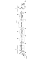
この露光装置においては、露光光源から所定の光学系を介して出射された露光光は、マスクの光透過領域のパターンを透過して照射され、露光対象部材が例えばガラス基板の場合には、ガラス基板は、移動可能なステージ上に載置され、ステージを移動させることにより、露光光の照射領域に搬送される。そして、ガラス基板上に形成された配向材料膜を、マスクのパターンに対応させて露光することにより光配向させて、所定の露光領域を形成することが行われている。又は、露光対象部材がフィルム等の柔軟性を有する部材の場合においては、例えば図6に示すようなロールトゥロール方式による露光が行われている。即ち、図6に示すように、露光対象のフィルムは、フィルム基材から製品としてのフィルムに加工されるまでの各工程間をロール状に巻き取られて搬送される。そして、露光装置10に供給される際には、供給側のローラ80にフィルムのロールが同軸的に取り付けられ、フィルムは先端部から巻き取り側ローラ81により順次巻き取られていく。そして、図6に示すように、供給側のローラ80から巻き取り側のローラ81に至るまでの間に、露光装置10を通過させ、フィルムの表面に形成された例えば配向材料膜に露光光を連続的に照射して、フィルムの所定の露光領域をフィルムの移動方向に沿って露光する。フィルムは、例えば搬送ローラ9等に張架され、搬送ローラの回転により各装置間を搬送される。
近時、3D(Three Dimensional)液晶ディスプレイ等の表示装置が、ますます注目を浴びるようになってきているが、この表示装置に使用されるガラス基板又は偏光フィルム等の露光対象部材2の表面に配向膜を形成する場合には、例えば1画素又は1絵素に対応する領域を例えばその幅方向に2分割し、分割領域ごとに配向方向が異なる配向膜を形成することが行われている。これにより、同一の画素又は絵素に対応する領域において、2種類のプレチルト角を有する表示光を透過させることができ、表示装置の視野角を広げたり、2種類の表示光を、夫々、例えば右目用及び左目用の表示光として使用することができる。このように、露光対象領域を分割して、夫々に形成する配向膜を異なる方向に配向させる露光装置は、配向分割方式と称されている。
図7は、露光光を出射する露光光源11が1個のマスク12に対応して1対ずつ向かい合わせて配置され、互いに異なる方向から露光光を照射する型式の従来の露光装置を一例として示す図である。このように、配向分割方式の露光装置においては、1の露光領域を分割して、夫々の分割領域に対して露光光を異なる方向から照射することにより、配向材料膜を異なる方向に配向させることができる。
図8(a)は従来の配向分割方式の露光装置を使用した場合における露光対象部材及びマスクの配置を一例として示す図、図8(b)はこの配向分割方式の露光装置で使用されるマスクを一例として示す図である。図8(a)に示すように、1枚の露光対象部材2からは、複数枚のガラス基板又は偏光フィルム等が製造され、基材上には、複数の(例えば3行×3列の)露光パターン形成用領域に配向材料膜21が形成されている。マスク12は、複数枚の(例えば2行×3列の)ガラス基板又は偏光フィルム等となる領域を覆う大きさで設けられている。図8(b)に示すように、マスク12のパターン形成部125には、1方向に延びる複数本の光透過領域のパターン125aが互いに平行に設けられており、このパターン125aの透過光により、複数枚のガラス基板又は偏光フィルム等に対応する領域を同時に露光する。各パターン125aは、画素又は絵素に対応する間隔で互いに離隔して形成されており、各パターン125aの幅は、1画素の半分又は1絵素の半分の幅に対応する幅で形成されている。図8(a)に示すように、この露光装置においては、1画素又は1絵素の半分の領域を露光した後、露光光の照射を一旦停止し、露光対象部材2の未露光の部分に露光光が照射されるようにマスク12を移動させた後、再度、異なる照射角度から露光光を照射して露光する。これにより、配向方向が異なる配向膜21aを互いに隣接するように形成することができる(図9(a))。なお、図面の配向膜21aにおける斜線は、夫々配向膜21aの配向方向を示す。なお、1枚の露光対象部材2から複数個のガラス基板又は偏光フィルム等を製造する場合には、配向膜21aを形成する領域は、露光対象部材2の幅方向及び/又は長さ方向に並ぶように配置されている(図10)。各露光パターン形成用領域間の領域は、材料膜が形成されないか、又は露光されない非パターン形成領域である。
図11(a)は他の配向分割方式の露光装置を使用した場合における露光対象部材及びマスクの配置を示す図である。この露光装置においては、マスク12は1枚のガラス基板又は偏光フィルム等となる領域に対して2個ずつ設けられている。即ち、図11(a)に示すように、各マスク12は、1のガラス基板又は偏光フィルム等となる領域を列方向に覆う大きさで設けられている。そして、各マスクのパターン125aは、1画素の半分又は1絵素の半分の幅に対応する幅で複数本形成されており、1画素又は1絵素に対応する間隔で互いに離隔している。マスク12は、一方のマスク121により形成されるパターンが他方のマスク122により形成されるパターンと互いに隣接するように配置されており、各マスク12に対応して設けられた露光光源11から互いに異なる角度の露光光を出射し、各マスク12に夫々異なる方向から露光光を透過させる。そして、露光光の照射領域に露光対象部材2を連続的に供給して連続露光することにより、露光対象部材2の移動方向に沿ってパターンを帯状に形成する。これにより、上記の場合と同様に、配向方向が異なる配向膜21aを互いに隣接するように形成することができる(図11(b))。
図12は、更に他の配向分割方式の露光装置を使用した場合における露光対象部材及びマスクの配置を示す図である。この露光装置においても、露光対象部材2は露光装置内に連続的に供給される。マスク12は露光対象部材2の移動方向の上流側及び下流側に夫々2個ずつ配置されている。このように、露光対象部材2の移動方向の上流側及び下流側に夫々マスク12を複数個配置するような配置は、マスク12の大きさをガラス基板又は偏光フィルム等となる領域よりも大きくできない場合、又は露光対象部材2が搬送中に波打ちを生じるフィルム等の部材である場合に好適である。即ち、各マスク12の位置をフィルム等の波打ちに応じて調整できるように構成することにより、波打ちによる露光位置のずれの影響を低減できる。図13は図12に示す露光装置の変形例である。図13に示すように、この露光装置においては、露光対象部材2の移動方向の上流側及び下流側に夫々マスク121,122及びマスク123,124が配置されており、互いに離隔して配置された上流側のマスク121,122によりフィルム2を露光領域A及びCにて露光し、下流側にて、露光領域A及びC間の領域Bをマスク123により露光し、露光領域Cに隣接する領域Dをマスク124により露光する。これにより、露光対象部材2のガラス基板又は偏光フィルム等となる領域のほぼ全面に配向分割したパターンを精度良く形成することができる。
上記従来の露光装置においては、1枚の表示装置用のガラス基板又は偏光フィルム等となる領域に配向膜21aを最大でも2回(図8に示すようなステップ露光の場合)の露光により形成することができる。一方、例えば、特許文献1には、周期的なパターンが形成された1枚のマスク12をパターンの間隔ずつずらしながら露光する技術が開示されており、照射エネルギーを分割して露光光を複数回照射することにより、隣接するパターン同士の境界に形成されるつなぎ目を目立たなくできることが開示されている。
しかしながら、上記従来技術には、以下のような問題点がある。特許文献1の技術は、1枚の露光対象部材2に対して、少なくともパターンの本数の回数の露光を行う必要があり、生産性が極めて低い。
また、露光対象部材2及び配向膜は、通常、光の透過率が非常に高い材料により形成されているため、例えばマスク位置のずれ等により、図9(b)、図11(c)及び図12(c)に示すように、隣接する露光領域が重なって露光されている場合及び未露光の部分が残っている場合においては、その視認が困難である。よって、ガラス基板又は偏光フィルム等を液晶ディスプレイに組み立ててモジュール化し、液晶を実際に駆動させるまで、露光領域の重なり又は未露光領域の有無を確認することができない。そして、露光不良の領域が存在した場合、モジュール化した表示装置の全体が無駄になってしまうという問題点がある。
本発明はかかる問題点に鑑みてなされたものであって、露光パターン形成用領域を複数回に分けて露光する場合、又は複数の露光パターン形成用領域を同時若しくは連続的に露光する場合に、露光位置の確認が容易な露光方法及び露光位置の確認方法を提供することを目的とする。
本発明に係る露光方法は、露光パターン形成用領域及びその周囲の少なくとも一部の非パターン形成領域を備えた露光対象部材に対して、露光光源から出射した露光光をマスクを介して照射することにより、前記露光パターン形成用領域に前記マスク上のマスクパターンを露光する露光方法において、前記非パターン形成領域における露光パターンの延長上にある領域に前記露光光の照射により変色する光変色材料を塗布するか、又は前記露光光の照射により変色する光変色部材を貼付し、前記マスクに透過させた露光光を前記露光対象部材に照射する際に、前記露光パターン形成用領域の他に、前記光変色材料又は前記光変色部材にも照射してこれを変色させることを特徴とする。
前記光変色材料又は光変色部材は、例えば前記露光光の照射回数及び/又は照射時間により、変色の度合いが異なることが好ましい。
上述の露光方法において、例えば前記露光対象部材には、前記露光パターン形成用領域が複数形成されており、この露光パターン形成用領域間に前記非パターン形成領域が形成されている。
例えば前記露光対象部材の2以上の露光パターン形成用領域を同時露光する際には、露光対象の露光パターン形成用領域間の非パターン形成領域に前記光変色材料又は前記光変色部材を施工する。
又は、上述の露光方法は、例えば前記露光光を前記マスクに連続的に透過させながら前記露光対象部材を1方向に移動させて前記露光対象部材の移動方向に並ぶ複数の露光パターン形成用領域を連続的に露光する露光方法であって、前記露光対象部材の移動方向に並ぶ前記パターン形成用領域間の非パターン形成領域に前記光変色材料又は前記光変色部材を施工するものである。
本発明に係る露光位置の確認方法は、上述の露光方法により露光された露光対象部材における露光位置の確認方法であって、前記露光光の照射により変色させた前記光変色材料又は光変色部材の変色により、前記露光パターン形成領域における露光位置を確認することを特徴とする。
本発明に係る露光方法は、露光パターン形成用領域及びその周囲の少なくとも一部に非パターン形成領域を備えた露光対象部材を使用し、露光対象部材の非パターン形成領域における露光パターンの延長上にある領域に露光光の照射により変色する光変色材料を塗布するか、又は露光光の照射により変色する光変色部材を貼付し、マスクに透過させた露光光を露光対象部材に照射する際に、露光パターン形成用領域の他に、光変色材料又は光変色部材にも照射してこれを変色させる。よって、光変色材料又は光変色部材の変色により、露光パターン形成用領域における露光位置を容易に確認することができる。
よって、本発明に係る露光位置の確認方法は、露光位置の確認が容易である。
また、本発明に係る露光方法及び露光領域の確認方法によれば、実際にガラス基板又は偏光フィルム等を液晶ディスプレイ等の表示装置に組み立てて液晶を実際に駆動させなくても、露光位置の重なり又は未露光領域等の露光不良の有無を確認することができ、表示装置を無駄にすることがない。
以下、添付の図面を参照して本発明の実施形態について具体的に説明する。第1実施形態は、露光対象部材2の2以上の露光パターン形成用領域を同時露光する場合である。図1(a)は本発明の第1実施形態に係る露光方法を示す図、図1(b)は図1(a)のA部拡大図、図1(c)は露光位置の重なり及び未露光領域が発生した場合を示すA部拡大図である。図2は、本実施形態におけるマスクを一例として示す図である。図1(a)に示すように、本実施形態においては、露光対象部材2の表面には、3行×3列の露光パターン形成用領域に配向材料膜21が形成されており、マスク12は、2行×3列の配向材料膜21が形成された領域を覆う大きさで設けられており、マスク12の光透過領域のパターン125aは、露光パターン形成用領域の行方向に延びるように複数本が互いに平行となるように形成されている。そして、このマスク12により、2行×3列の配向材料膜21を同時露光する。本発明は、非パターン形成用領域における露光パターンの延長上にある領域に露光光の照射により変色する光変色材料を塗布するか、又は露光光の照射により変色する光変色部材を貼付して光変色領域22を形成し、露光光を露光対象部材に照射する際に、露光パターン形成用領域の他に、光変色領域22にも照射してこれを変色させるものである。本実施形態においては、光変色領域22は3列に並ぶ配向材料膜21の行間の非パターン形成用領域に形成されている。即ち、この光変色領域22は、少なくとも1のパターン125aにより同時に露光される配向材料膜21間の領域に形成されており、パターン125aを透過した露光光の照射により変色させて、露光位置の確認に使用する。なお、図1(a)においては、マスク12により露光される露光領域のうち、列方向の1画素又は1絵素の領域のみに配向膜21aが形成された場合を図示してある。
本実施形態に係る露光装置1は、図6乃至図8に示す従来の露光装置と同様に、露光光を出射する露光光源11と、マスク12と、露光光源11から出射した露光光をマスク12を介してフィルム2に照射する光学系と、フィルム2を搬送する例えば搬送ローラ等のフィルム搬送部と、を有しており、例えばコリメータレンズ及び/又は反射鏡等の光学系により、露光光源11から出射した露光光を、マスク12を介して、表面に配向材料膜21が形成されたガラス基板又はフィルムの露光対象部材2に照射し、マスクパターンに対応させて配向材料膜21を光配向させて配向膜21aを形成する。なお、露光対象部材2がガラス基板の場合には、搬送ステージ等の可動の搬送装置にガラス基板を載置して搬送して露光光の照射位置にパターン形成用領域の配向材料膜21を配置し、露光の際は、搬送を停止する。又は、露光対象部材がフィルムの場合には、従来と同様に、ロールトゥロール方式により、供給側のローラ80から供給したフィルム2を巻き取り側のローラ81によりフィルムの緊張状態を維持しながら巻き取る間に、露光光の照射位置にパターン形成用領域の配向材料膜21を形成し、露光の際は、搬送を停止する。フィルム用の搬送装置としては、例えば、上記2個のローラ80,81間にもフィルム搬送用の搬送ローラ9が1以上配置されており、各搬送ローラ9等は、例えばモータにより駆動されている。本実施形態においては、露光対象部材2がガラス基板である場合について説明するが、露光対象部材2がフィルムの場合においても、搬送装置の構成以外については、本実施形態と同様である。
露光光源11は、例えば紫外光を出射する光源であり、例えば水銀ランプ、キセノンランプ、エキシマランプ及び紫外LED等であって、連続光又はパルスレーザ光を出射する光源が使用される。本実施形態においては、露光光源11から出射した露光光の光路上には、例えばコリメータレンズ及び/又は反射鏡等の光学系が配置されており、例えば露光対象のガラス基板20上の露光パターン形成用領域に形成された配向材料膜21に所定の光量で露光光が照射されるように構成されている。露光光源11は、例えば図示しない制御装置により、露光光の出射方向を調整することができ、これにより、露光対象部材2に対する露光光の入射角を調整可能に構成されている。
マスク12は、図2に示すように、例えば枠体120とその中央のパターン形成部125により構成されており、パターン形成部125には、所定の光透過領域のパターン125aが形成されている。即ち、パターン形成部125には、フィルム2に形成するパターン形状に対応して、露光光を透過する開口が形成されているか、又は光透過性の部材が設置されている。このパターン125aは、例えば従来のマスクと同様に、露光パターン形成用領域の行方向に延びる複数本の光透過領域により構成されており、各パターン125aは、画素又は絵素に対応する間隔で互いに離隔しており、各パターン125aの幅は、1画素の半分又は1絵素の半分の幅に対応する幅で形成されている。そして、パターン125aの透過光により露光対象部材2の表面の配向材料膜21にマスクパターンを露光する。上述の如く、本実施形態においては、1個のマスク12により、2行×3列の配向材料膜21を同時露光する。
本実施形態においては、マスク12には、パターン125aとは異なる位置に例えば幅が300μm程度、長さが250mm程度のラインCCD用の覗き窓12aが設けられており、この覗き窓12aの長手方向の中間に露光光を遮光する例えば幅が15μm程度のライン状の遮光パターン12bが設けられている。そして、マスク12の下方には、例えばマスク位置検出用のラインCCD15が設けられており、ラインCCD15により遮光パターン12bの位置を検出し、マスク12の位置調整に使用できる。なお、本実施形態における覗き窓12a及び遮光パターン12bの位置及び形状は、一例であり、これらの位置及び形状により本発明が限定されるものではない。例えば遮光パターン12bの代わりに、互いに(例えばN型に)交差する複数本のスリットが設けられていてもよい。また、マスク12の位置調整を精度よく行うことができる限り、これらの構成は設けられていなくてもよい。
マスク12は、例えば枠体120の部分がマスクステージ17(図7参照)により支持されており、マスクステージ17の移動によりマスク12の全体が移動可能に構成されている。マスクステージ17は、例えば図3に示すような制御装置30に接続されており、制御装置30による制御により、その位置を、例えば水平方向(ガラス基板20の列方向、又はガラス基板20の列方向及び行方向)に移動可能に構成されている。これにより、マスク12による配向材料膜21の露光位置を水平方向に調整することができる。マスクステージ17は、例えば鉛直方向にも移動可能であり、これにより、ガラス基板20上の配向材料膜21が所定の大きさで露光されるように調整可能に構成されている。
図3はマスク位置を制御する制御装置30の構成を一例として示す図である。図3に示すように、制御装置30は、例えばマスクステージ駆動部及びフィルムの巻き取り側のローラ81に設けられたモータの制御部に接続されている。制御装置30は、マスク12の下方に設けられたマスク位置検出用のラインCCD15に接続された第1画像処理部31と、第2実施形態の変形例において後述するアライメントマーク2aの位置検出用のラインCCD14に接続された第2画像処理部32と、モータ駆動制御部33と、演算部34と、メモリ35と、マスクステージ駆動制御部36と、制御部37とを備えている。
第1画像処理部31は、マスク位置検出用のラインCCD15により撮像されたマスク12の遮光パターン12bの画像処理を行い、露光パターン形成用領域の列方向における遮光パターン12bの位置を検出する。第2画像処理部32は、アライメントマーク検出用のラインCCD14により撮像されたアライメントマーク2aの画像処理を行い、露光パターン形成用領域の列方向におけるアライメントマーク2aの位置を検出する。モータ駆動制御部33は、例えば露光対象部材2がフィルムの場合に、巻き取り側のロール81のモータの駆動若しくは停止、又は駆動されている際の回転速度を制御する。演算部34は、各ラインCCDにより検出されたマスク位置、又はマスク位置及びアライメントマーク2aの位置により、各検出対象の変位又は蛇行量を演算する。即ち、演算部34は、第1画像処理部31の検出結果により、マスク12の設定すべき位置からのずれを演算する。また、露光対象部材2にアライメントマーク2aが形成されている場合には、演算部34は、第1画像処理部31及び第2画像処理部32の検出結果により、設定すべき両者間の相対的位置関係と実際の両者間の相対的位置関係とにより、設定すべき両者間の距離からのずれを演算する。メモリ35は、例えば第1画像処理部31及び第2画像処理部32の検出結果並びに演算部34の演算結果を記憶する。
マスクステージ駆動制御部36は、マスクステージ17の駆動を制御するものであり、例えばマスクステージ17の移動方向及び移動量を制御することにより、マスク位置を調整できる。制御部37は、これらの第1及び第2画像処理部31,32、モータ駆動制御部33、演算部34、メモリ35及びマスクステージ駆動制御部36を制御する。これにより、露光装置1は、例えばマスク12の位置を、例えば露光パターン形成用領域の列方向に調整したり、露光対象部材2がフィルムの場合に、巻き取り側のローラ81に設けられたモータの回転速度等を制御できるように構成されている。
本実施形態においては、露光対象のガラス基板20は、露光装置10に供給される前に、例えばスリットコーター4に供給され、スリットコーター4にてガラス基板20の表面の所定の領域に光配向性の材料が膜状に塗布されている。そして、材料が塗布されたガラス基板20は、例えば乾燥装置5に供給され、光配向性の材料が乾燥装置5にて乾燥又は焼成される。これにより、ガラス基板20の表面の所定の領域には、配向材料膜21が形成されている。
また、本実施形態においては、スリットコーター4は、例えば3列に並ぶ配向材料膜21の行間の非パターン形成用領域に光変色材料も塗布して光変色領域22を形成できるように構成されている。又は、光変色材料は、光配向性の材料を塗布するスリットコーター4とは異なる他の塗布装置により塗布されている。なお、光変色領域22を露光光の照射により変色する光変色部材の貼付により形成する場合においては、光変色部材は、露光装置に供給される前に、例えば貼付装置等により貼付される。
本実施形態において、光変色領域22を構成する光変色材料としては、例えば一般的なフォトクロミズム材料を使用することができる。フォトクロミズム材料としては、例えばアゾベンゼン、ジアリールエテン等を挙げることができる。そして、これらの成分を含有する液状又はペースト状の材料を配向材料膜間の非パターン形成領域に塗布する。光変色領域22を光変色部材により形成する場合においては、光変色部材としては、例えば紫外光等の露光光の照射により変色するUVラベル等のテープ又はシート状の部材を使用することができる。非パターン形成領域において、露光光の照射により変色する光変色領域22を形成することにより、パターン形成用領域における未露光の領域を確認することができる。即ち、本実施形態においては、光変色領域22は、少なくとも1のパターン125aにより同時に露光される配向材料膜21間の領域に形成されているため、光変色領域22の変色していない領域に対応するパターン形成用領域の配向材料膜21は未露光であると判定できる。
光変色材料及び光変色部材としては、露光光の照射回数及び/又は照射時間により、変色の度合いが異なるものを使用することが好ましい。即ち、光変色領域22に露光光を複数回照射した場合に、その変色の度合いが異なることを視認できることにより、露光位置の重なり及び露光回数等を判定できる。
次に、本実施形態の露光装置の動作について説明する。先ず、露光対象のガラス基板20は、露光装置1に供給される前に、配向材料膜21が形成され、また、光変色領域22となる光変色材料が塗布されるか、又は光変色部材が貼付される。即ち、ガラス基板20は、表面に露光材料膜が施工されていない状態で、スリットコーター4に供給され、スリットコーター4により、配向材料膜21となる材料が塗布される。本実施形態においては、スリットコーター4は、配向材料膜21となる材料をガラス基板20の搬送により列方向に3列塗布していき、これを間欠的に3回繰り返すことにより、材料の塗布領域を行方向に3行形成する。また、スリットコーター4が液状又はペースト状の光変色材料を塗布可能に構成されている場合には、スリットコーター4は、3列に並ぶ配向膜材料の行間の非パターン形成用領域に光変色材料も塗布する。
又は、光変色材料用の塗布装置がスリットコーター4とは別に設けられている場合には、この塗布装置により3列に並ぶ配向膜材料の行間の非パターン形成用領域に光変色材料を塗布する。これにより、ガラス基板20の表面には、液状又はペースト状の配向膜材料及び光変色材料が塗布される。
所定の露光材料が塗布されたガラス基板20は、乾燥装置5に搬送され、表面の液状又はペースト状の露光材料が乾燥される。これにより、ガラス基板20の表面には、配向材料膜21、及び光変色材料からなる光変色領域22が形成される。即ち、ガラス基板20上には、配向材料膜21からなる露光パターン形成用領域が3行×3列形成され、3列に並ぶ配向材料膜21の行間の非パターン形成用領域には、光変色材料からなる光変色領域22が形成される。なお、光変色材料は、乾燥する必要がない場合及び乾燥により光変色特性が変化する場合には、乾燥装置5による配向膜材料の乾燥後に塗布してもよい。なお、光変色領域22を露光光の照射により変色する光変色部材により形成する場合においては、露光装置に供給する前に、配向膜材料の行間の非パターン形成用領域にテープ又はシート状のUVラベル等の部材を貼付する。
そして、表面に3行×3列の配向材料膜21からなる露光パターン形成用領域及びその行間の光変色領域22が形成されたガラス基板20は、例えば搬送ステージ等の搬送装置に載置され、露光装置1内に供給されていく。搬送装置による搬送により、ガラス基板20は、マスク12の下方に配置される。本実施形態においては、マスク12は、2行×3列の配向材料膜21が形成された領域を覆う大きさで形成されており、このマスクの下方にガラス基板20上の2行×3列の配向材料膜21が配置される。
ガラス基板20が所定の位置まで搬送されたら、露光光源11から露光光を出射し、図2に示すマスク12のパターン125aに露光光を透過させて、ガラス基板上の配向材料膜21に照射し、これを露光する。本実施形態においては、1パターンにより同時に露光される配向材料膜21間の領域には、光変色領域22が形成されており、この光変色領域にもパターン125aの透過光を照射する。これにより、配向材料膜21は、露光光の照射領域において光配向し、露光光の照射角度に応じて特定の配向方向を有する配向膜21aが形成される。また、光変色領域22の光変色材料又は光変色部材は、露光光の照射により、例えば露光光の照射時間に応じて、特定の変色を呈する。例えば、光変色領域22は、有色の光変色材料又は光変色部材により構成されており、露光光の照射時間が長いほどその色が薄くなる。又は、光変色領域22は、無色の光変色材料又は光変色部材により構成されており、露光光の照射により特定の色を呈するようになり、露光光の照射時間が長いほど色が濃くなる。なお、露光領域の確認を容易にするためには、光変色領域22を構成する材料又は部材は、後者の変色特性を有することが好ましい。
本実施形態においては、上記露光が所定時間行われたら、一旦、露光光の照射を停止する。そして、例えばマスクステージ17を移動させることにより、図1(a)に示すように、マスク12を列方向に移動させる。本実施形態においては、マスク12のパターン125aは、画素又は絵素に対応する間隔で互いに離隔しており、各パターン125aの幅は、1画素の半分又は1絵素の半分の幅に対応する幅で形成されている。よって、1回目の露光により、1画素の半分又は1絵素の半分の幅に対応する配向膜21aが形成され、各配向膜21a間は、1画素の半分又は1絵素の半分ずつ離隔している。よって、マスク12を、1画素の半分又は1絵素の半分に対応する距離だけ列方向に移動させる。また、露光光源11については、例えば、露光光を1回目の出射方向に対して異なる方向から出射するように、調整する。なお、本実施形態においては、1回目の露光により形成される配向膜の配向方向と2回目の露光により形成される配向膜の配向方向とが異なるように、配向膜を形成すればよい。よって、上記のように、露光光の出射方向を変更する態様の他、例えば1回目と2回目の各露光において、配向材料膜21に照射する露光光を相互に偏光方向が異なる露光光とすることによっても、相互に配向方向が異なる配向膜を形成することができ、例えば露光光の出射方向を変更することなく本実施形態と同様の配向膜を得ることができる。
マスク12の移動及び露光光の出射角度の調整が終了したら、露光光源11からの露光光の出射を再開し、図2に示すマスク12のパターン125aに露光光を透過させて、ガラス基板上の配向材料膜21を露光する。このとき、1パターンにより同時に露光される配向材料膜21間の領域に形成された光変色領域22にもパターン125aの透過光を照射する。これにより、図1(b)に示すように、1回目の露光により形成された配向膜21aに隣接する未露光の領域が露光され、1回目の露光とは異なる方向に配向した配向膜21aが形成される。そして、露光パターン形成用領域の行間の光変色領域22も、露光パターン形成用領域に形成された配向膜21aに対応する位置で変色する。
本実施形態においては、1回目の露光と2回目の露光との間で、マスク12を移動させるが、この位置がずれた場合、マスク12のパターン125aを透過した露光光の照射位置もずれてしまう。よって、図1(c)に示すように、露光位置の重なり及び/又は未露光の領域が発生してしまう。ガラス基板20等の露光対象部材2及び配向膜21aは、光の透過率が非常に高い材料により形成されているため、例えばマスク位置のずれ等が生じて図9(b)、図11(c)及び図12(c)に示すような露光位置の重なり及び/又は未露光の領域が発生した場合においても、その視認が困難である。従来の露光方法においては、このような露光不良が生じても、ガラス基板又は偏光フィルム等の露光対象部材2を液晶ディスプレイに組み立ててモジュール化し、液晶を実際に駆動させるまで、露光位置の重なり又は未露光領域の有無を確認することができず、モジュール化した表示装置の全体が無駄になってしまうという問題点があった。しかしながら、本実施形態においては、露光パターン形成用領域の行間の非パターン形成領域に光変色領域22が形成されており、露光光を露光対象部材2に照射する際に、露光パターン形成用領域の他に、光変色領域22にも照射して、これを露光パターン形成用領域に形成された配向膜21aに対応するように変色させる。よって、例えば露光位置の重なりが生じた場合においては、重なって露光された部分は、露光光の照射回数及び/又は照射時間が多くなり、変色の度合いが大きくなる。また、未露光の部分については、光変色領域22が変色しない。このように、本実施形態においては、露光不良の有無を変色により容易に判定することができる。よって、露光対象部材2を表示装置に組み立てる前に露光不良を確認でき、表示装置を無駄にすることがない。
なお、本実施形態のように、複数の露光パターン形成用領域を同時露光する場合には、光変色領域22は、少なくとも1のパターン125aにより同時に露光される配向材料膜21間の領域に形成されていればよい。即ち、図1(a)に示す配向材料膜21の上から3行目の3領域の配向材料膜21については、夫々、マスク12により同時に露光する他の配向材料膜21が存在しない。しかし、本発明においては、露光パターン形成用領域における露光パターンの延長上にある領域に光変色領域22を形成し、露光パターン形成用領域の露光の際に、露光光を光変色領域22にも照射してこれを変色させ、これにより、露光不良の有無を確認できればよい。よって、例えば、図1(a)の上から3行目の配向材料膜21については、例えば配向材料膜21の夫々に対応するように、図1(a)における上方又は下方の非パターン形成領域に光変色領域22を形成し、各配向材料膜21と同時に露光することにより、露光不良の有無を判定することができる。
次に、本発明の第2実施形態に係る露光装置について説明する。第1実施形態においては、1個のマスクにより複数の露光パターン形成用領域を同時露光する工程を、マスクの移動を挟んで2度繰り返すステップ露光について説明したが、本実施形態においては、複数個のマスク12(121乃至124)を使用し、各マスク12に連続的に露光光を透過させて、露光パターン形成用領域を連続露光する場合について説明する。図4(a)は本第2実施形態に係る露光方法を示す図、図4(b)は図4(a)のB部拡大図、図4(c)は露光位置の重なり及び未露光の領域が発生した場合を示すB部拡大図である。
本実施形態においても、マスクの個数及び連続露光する点以外の構成については第1実施形態と同様であり、露光パターン形成用領域に対応するように光変色領域22を形成し、光変色領域22を配向材料膜21の露光位置に対応させて露光する。これにより、露光不良が発生しなかった場合には、図4(b)に示すように、光変色部材22は均等に変色する。しかし、例えば、複数個のマスク12のうち、1つでもその位置がずれていた場合には、図4(c)に示すように、露光位置の重なり及び/又は未露光の領域が発生してしまう。しかし、本実施形態においても、露光パターン形成用領域の行間の非パターン形成領域に光変色領域22が形成されており、露光光を露光対象部材に照射する際に、露光パターン形成用領域の他に、光変色領域22にも照射して、これを露光パターン形成用領域に形成された配向膜21aに対応するように変色させるため、露光不良の有無を光変色領域22の変色により容易に判定することができる。よって、露光対象部材2を表示装置に組み立てる前に露光不良を確認でき、表示装置を無駄にすることがない。
以上述べた実施形態の露光方法において、マスク及び露光パターン形成用領域の配置は一例であり、露光パターン形成用領域に対応するように光変色領域22を形成し、露光パターン形成用領域の露光の際に、露光光を光変色領域22にも照射してこれを変色させ、これにより、露光不良の有無を確認できるように構成できれば、本発明は種々の態様に適用することができる。例えば、図11及び図13に示すような従来の露光方法において、露光パターン形成用領域の行間の領域に光変色領域22を形成すれば、本発明の効果を得ることができる。
次に、本実施形態の変形例として、露光対象部材2がフィルムである場合について説明する。露光対象部材2がフィルムであり、これを特に連続露光により露光する場合においては、フィルムは、その移動方向に垂直の方向に蛇行する場合がある。よって、マスク12が所定の位置に配置されていても、フィルムが蛇行した場合には、露光位置の重なり又は未露光の領域が発生してしまう。
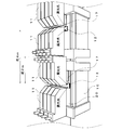
本変形例においては、このフィルムの蛇行を解消するために、図5に示すように、フィルムの側部に蛇行検出用のアライメントマーク2aを形成するアライメント用レーザマーカ13が設けられており、フィルムの移動方向における各マスクに対応する位置には、例えばアライメントマーク検出用のラインCCD14が設けられている。
アライメント用レーザマーカ13は、例えばNd:YAGレーザ又は紫外光等を照射するレーザ光源を備えており、例えばキセノンフラッシュランプ等のパルス光源によりパルスレーザ光を出射してフィルムの縁部から例えば25mm以内の側部に、例えば幅が20μm、長さが15mm程度のアライメントマーク2aを断続的に形成する。又は、アライメント用レーザマーカ13は、連続したアライメントマーク2aを形成する。
ラインCCD14は、例えばマスク12の覗き窓12aに対応する位置にて、フィルムの移動方向に交差する方向におけるアライメントマーク2aの位置を検出する。例えば、フィルムが移動する間にその幅方向に蛇行した場合、それに伴って、アライメントマーク2aも同一の蛇行量だけフィルムの幅方向にずれるが、アライメントマーク検出用のラインCCD14は、蛇行により幅方向にずれたアライメントマーク2aの位置を検出する。
ラインCCD14は、例えば図3に示すような制御装置30に接続されている。そして、検出したアライメントマーク2aのフィルム幅方向における位置を制御装置30に送信する。制御装置30は、ラインCCD14から送信されたアライメントマーク2aの位置に基づいて、各マスク12の位置を調整するように構成されている。これにより、本変形例に係る露光装置は、アライメントマーク2aの蛇行量によりマスク12の位置を調整することができる。
即ち、マスク12の位置を調整する際には、露光装置は以下のように動作する。先ず、側部にアライメントマーク2aが形成されたフィルムは、搬送されてくる間に、その移動方向に垂直の幅方向に蛇行する。マスクの覗き窓12a及び遮光パターン12bに対応する位置には、フィルムの幅方向に延びるようにラインCCD15が配置されており、ラインCCD15は、マスク12の覗き窓12aの中間に設けられた遮光パターン12bの位置をマスク12の位置として検出する。また、フィルムの移動方向におけるマスク12の覗き窓12a(及び遮光パターン12b)に対応する位置には、アライメントマーク検出用のラインCCD14が設けられており、フィルムの側部に形成されたアライメントマーク2aを検出する。これらのラインCCD14,15により検出された夫々マスク位置,アライメントマーク位置の信号は、制御装置30に送信され、各画像処理部(第1画像処理部31,第2画像処理部32)、演算部34及び制御部37等による処理を受けた後、マスクステージ駆動制御部36による制御により、マスクステージ17が駆動されることにより、アライメントマーク2aの位置を基準としてマスク位置を調整することができる。即ち、本変形例においては、アライメントマーク2aの位置を基準としてマスク位置を補正することにより、フィルムに蛇行が生じた場合においても、マスク12の位置を調整することにより、露光位置の重なり及び未露光領域の発生を防止することができる。
しかし、仮に、上記のような露光不良が発生した場合においても、光変色領域22の変色により露光不良の有無を容易に確認することができ、露光対象部材2を表示装置に組み立てる前に露光不良を確認でき、表示装置を無駄にすることもない。
本発明においては、露光対象部材の非パターン形成領域における露光パターンの延長上にある領域に露光光の照射により変色する光変色材料を塗布するか、又は露光光の照射により変色する光変色部材を貼付し、露光光を光変色材料又は光変色部材にも照射してこれを変色させるので、露光パターン形成用領域における露光位置を容易に確認でき、特に、光の透過率が高い材料からなる露光対象部材の露光に有益である。
1,10:露光装置、12:マスク、12a:覗き窓、12b:遮光パターン、120:枠体、121:(第1の)マスク、122:(第2の)マスク、123:(第3の)マスク、124:(第4の)マスク、125:パターン形成部、125a:(マスク)パターン、13:アライメント用レーザマーカ、14:(アライメントマーク検出用)ラインCCD、17:マスクステージ、2:露光対象部材、2a:アライメントマーク、20:ガラス基板、21:配向材料膜、22:光変色領域、30:制御装置、31:第1画像処理部、32:第2画像処理部、33:モータ駆動制御部、34:演算部、35:メモリ、36:マスクステージ駆動制御部、37:制御部
Claims (6)
- 露光パターン形成用領域及びその周囲の少なくとも一部の非パターン形成領域を備えた露光対象部材に対して、露光光源から出射した露光光をマスクを介して照射することにより、前記露光パターン形成用領域に前記マスク上のマスクパターンを露光する露光方法において、
前記非パターン形成領域における露光パターンの延長上にある領域に前記露光光の照射により変色する光変色材料を塗布するか、又は前記露光光の照射により変色する光変色部材を貼付し、前記マスクに透過させた露光光を前記露光対象部材に照射する際に、前記露光パターン形成用領域の他に、前記光変色材料又は前記光変色部材にも照射してこれを変色させることを特徴とする露光方法。 - 前記光変色材料又は光変色部材は、前記露光光の照射回数及び/又は照射時間により、変色の度合いが異なることを特徴とする請求項1に記載の露光方法。
- 前記露光対象部材には、前記露光パターン形成用領域が複数形成されており、この露光パターン形成用領域間に前記非パターン形成領域が形成されていることを特徴とする請求項1又は2に記載の露光方法。
- 前記露光対象部材の2以上の露光パターン形成用領域を同時露光する際に、露光対象の露光パターン形成用領域間の非パターン形成領域に前記光変色材料又は前記光変色部材を施工することを特徴とする請求項3に記載の露光方法。
- 前記露光光を前記マスクに連続的に透過させながら前記露光対象部材を1方向に移動させて前記露光対象部材の移動方向に並ぶ複数の露光パターン形成用領域を連続的に露光する露光方法であって、前記露光対象部材の移動方向に並ぶ前記パターン形成用領域間の非パターン形成領域に前記光変色材料又は前記光変色部材を施工することを特徴とする請求項3に記載の露光方法。
- 前記請求項1乃至5のいずれかの露光方法により露光された露光対象部材における露光位置の確認方法であって、前記露光光の照射により変色させた前記光変色材料又は光変色部材の変色により、前記露光パターン形成領域における露光位置を確認することを特徴とする露光位置の確認方法。
Applications Claiming Priority (2)
| Application Number | Priority Date | Filing Date | Title |
|---|---|---|---|
| JP2010253113A JP5688637B2 (ja) | 2010-11-11 | 2010-11-11 | 露光方法及び露光位置の確認方法 |
| JP2010-253113 | 2010-11-11 |
Publications (1)
| Publication Number | Publication Date |
|---|---|
| WO2012063633A1 true WO2012063633A1 (ja) | 2012-05-18 |
Family
ID=46050785
Family Applications (1)
| Application Number | Title | Priority Date | Filing Date |
|---|---|---|---|
| PCT/JP2011/074456 Ceased WO2012063633A1 (ja) | 2010-11-11 | 2011-10-24 | 露光方法及び露光位置の確認方法 |
Country Status (3)
| Country | Link |
|---|---|
| JP (1) | JP5688637B2 (ja) |
| TW (1) | TW201227179A (ja) |
| WO (1) | WO2012063633A1 (ja) |
Cited By (2)
| Publication number | Priority date | Publication date | Assignee | Title |
|---|---|---|---|---|
| WO2017145975A1 (ja) * | 2016-02-22 | 2017-08-31 | 株式会社ブイ・テクノロジー | 偏光光照射装置 |
| CN108604030A (zh) * | 2016-02-22 | 2018-09-28 | 株式会社 V 技术 | 偏振光照射装置 |
Citations (6)
| Publication number | Priority date | Publication date | Assignee | Title |
|---|---|---|---|---|
| JPH01295261A (ja) * | 1988-02-22 | 1989-11-28 | Nippon Seiko Kk | 露光装置の位置合わせ方法及び装置 |
| JP2000214596A (ja) * | 1999-01-26 | 2000-08-04 | Dainippon Printing Co Ltd | 露光装置および感光性レジスト |
| JP2001060008A (ja) * | 1999-08-23 | 2001-03-06 | Sumitomo Metal Mining Co Ltd | 露光方法およびこれを用いた電子部品の製造方法 |
| JP2002148824A (ja) * | 2000-11-07 | 2002-05-22 | Matsushita Electric Ind Co Ltd | パターン形成方法及びプラズマディスプレイ表示装置 |
| JP2002162629A (ja) * | 2000-11-27 | 2002-06-07 | Fujitsu Ltd | 液晶表示装置用基板及びその製造方法及びそれを備えた液晶表示装置 |
| JP2007010851A (ja) * | 2005-06-29 | 2007-01-18 | Fujifilm Holdings Corp | 基板製造方法および露光装置 |
-
2010
- 2010-11-11 JP JP2010253113A patent/JP5688637B2/ja not_active Expired - Fee Related
-
2011
- 2011-10-24 WO PCT/JP2011/074456 patent/WO2012063633A1/ja not_active Ceased
- 2011-11-04 TW TW100140365A patent/TW201227179A/zh unknown
Patent Citations (6)
| Publication number | Priority date | Publication date | Assignee | Title |
|---|---|---|---|---|
| JPH01295261A (ja) * | 1988-02-22 | 1989-11-28 | Nippon Seiko Kk | 露光装置の位置合わせ方法及び装置 |
| JP2000214596A (ja) * | 1999-01-26 | 2000-08-04 | Dainippon Printing Co Ltd | 露光装置および感光性レジスト |
| JP2001060008A (ja) * | 1999-08-23 | 2001-03-06 | Sumitomo Metal Mining Co Ltd | 露光方法およびこれを用いた電子部品の製造方法 |
| JP2002148824A (ja) * | 2000-11-07 | 2002-05-22 | Matsushita Electric Ind Co Ltd | パターン形成方法及びプラズマディスプレイ表示装置 |
| JP2002162629A (ja) * | 2000-11-27 | 2002-06-07 | Fujitsu Ltd | 液晶表示装置用基板及びその製造方法及びそれを備えた液晶表示装置 |
| JP2007010851A (ja) * | 2005-06-29 | 2007-01-18 | Fujifilm Holdings Corp | 基板製造方法および露光装置 |
Cited By (2)
| Publication number | Priority date | Publication date | Assignee | Title |
|---|---|---|---|---|
| WO2017145975A1 (ja) * | 2016-02-22 | 2017-08-31 | 株式会社ブイ・テクノロジー | 偏光光照射装置 |
| CN108604030A (zh) * | 2016-02-22 | 2018-09-28 | 株式会社 V 技术 | 偏振光照射装置 |
Also Published As
| Publication number | Publication date |
|---|---|
| JP2012103562A (ja) | 2012-05-31 |
| JP5688637B2 (ja) | 2015-03-25 |
| TW201227179A (en) | 2012-07-01 |
Similar Documents
| Publication | Publication Date | Title |
|---|---|---|
| JP5424271B2 (ja) | 露光装置 | |
| WO2007141852A1 (ja) | 露光方法および露光装置 | |
| JP5685756B2 (ja) | フィルム露光方法 | |
| JP5688637B2 (ja) | 露光方法及び露光位置の確認方法 | |
| JP4304165B2 (ja) | 露光方法および露光装置 | |
| TWI550367B (zh) | 膜片曝光裝置以及膜片曝光方法 | |
| JP5678334B2 (ja) | 露光装置 | |
| JP5895422B2 (ja) | 露光装置 | |
| JP5817564B2 (ja) | 露光装置 | |
| TWI536115B (zh) | 膜片之曝光裝置 | |
| KR20190086884A (ko) | 패턴 성형 장치 | |
| JP2013064872A (ja) | 露光装置 | |
| JP4738887B2 (ja) | 露光装置 |
Legal Events
| Date | Code | Title | Description |
|---|---|---|---|
| 121 | Ep: the epo has been informed by wipo that ep was designated in this application |
Ref document number: 11839099 Country of ref document: EP Kind code of ref document: A1 |
|
| NENP | Non-entry into the national phase |
Ref country code: DE |
|
| 122 | Ep: pct application non-entry in european phase |
Ref document number: 11839099 Country of ref document: EP Kind code of ref document: A1 |