WO2012063531A1 - Dispositif de communication sans fil et système de communication sans fil - Google Patents
Dispositif de communication sans fil et système de communication sans fil Download PDFInfo
- Publication number
- WO2012063531A1 WO2012063531A1 PCT/JP2011/067434 JP2011067434W WO2012063531A1 WO 2012063531 A1 WO2012063531 A1 WO 2012063531A1 JP 2011067434 W JP2011067434 W JP 2011067434W WO 2012063531 A1 WO2012063531 A1 WO 2012063531A1
- Authority
- WO
- WIPO (PCT)
- Prior art keywords
- wireless communication
- control
- control data
- external device
- unit
- Prior art date
Links
Images


Classifications
-
- H—ELECTRICITY
- H04—ELECTRIC COMMUNICATION TECHNIQUE
- H04W—WIRELESS COMMUNICATION NETWORKS
- H04W4/00—Services specially adapted for wireless communication networks; Facilities therefor
- H04W4/80—Services using short range communication, e.g. near-field communication [NFC], radio-frequency identification [RFID] or low energy communication
-
- A—HUMAN NECESSITIES
- A61—MEDICAL OR VETERINARY SCIENCE; HYGIENE
- A61B—DIAGNOSIS; SURGERY; IDENTIFICATION
- A61B1/00—Instruments for performing medical examinations of the interior of cavities or tubes of the body by visual or photographical inspection, e.g. endoscopes; Illuminating arrangements therefor
- A61B1/00002—Operational features of endoscopes
- A61B1/00011—Operational features of endoscopes characterised by signal transmission
- A61B1/00016—Operational features of endoscopes characterised by signal transmission using wireless means
-
- G—PHYSICS
- G08—SIGNALLING
- G08C—TRANSMISSION SYSTEMS FOR MEASURED VALUES, CONTROL OR SIMILAR SIGNALS
- G08C17/00—Arrangements for transmitting signals characterised by the use of a wireless electrical link
- G08C17/02—Arrangements for transmitting signals characterised by the use of a wireless electrical link using a radio link
-
- A—HUMAN NECESSITIES
- A61—MEDICAL OR VETERINARY SCIENCE; HYGIENE
- A61B—DIAGNOSIS; SURGERY; IDENTIFICATION
- A61B17/00—Surgical instruments, devices or methods, e.g. tourniquets
- A61B2017/00017—Electrical control of surgical instruments
- A61B2017/00221—Electrical control of surgical instruments with wireless transmission of data, e.g. by infrared radiation or radiowaves
-
- A—HUMAN NECESSITIES
- A61—MEDICAL OR VETERINARY SCIENCE; HYGIENE
- A61B—DIAGNOSIS; SURGERY; IDENTIFICATION
- A61B17/00—Surgical instruments, devices or methods, e.g. tourniquets
- A61B2017/00017—Electrical control of surgical instruments
- A61B2017/00225—Systems for controlling multiple different instruments, e.g. microsurgical systems
Definitions
- the present invention relates to a wireless communication device and a wireless communication system that perform wireless communication of control data for remotely controlling an external device.
- Priority is claimed on Japanese Patent Application No. 2010-251969, filed Nov. 10, 2010, the content of which is incorporated herein by reference.
- a surgical system which is configured of a plurality of medical device groups on which a medical device according to the purpose is mounted on a cart. Medical devices are freely arranged according to the contents of the operation.
- remote control a remote controller
- Many remote controls transmit control data to medical devices by infrared communication. Since the communication distance of infrared communication is short, transmission of control data by infrared communication causes a problem that control data can not be transmitted when the medical device is disposed in a wide range.
- Patent Document 1 discloses a method of increasing the amount of infrared light by means of an infrared adapter and transmitting control data to medical devices distant from each other.
- this method does not solve the problem associated with infrared communication that communication can not be performed if the communication partner is not at a communicable position, and thus there remains a problem that control data can not be transmitted depending on the arrangement of medical devices and doctors. .
- Patent Document 2 discloses the use of a remote control using a radio (radio wave) having a long communication distance.
- a radio radio wave
- Patent Document 3 discloses a method of preventing a collision by performing detection before transmission when communicating between remote controls.
- this method does not consider the occurrence of radio communication or electromagnetic noise other than communication between remote controls, and is an effective method when the generated radio communication or electromagnetic noise is small, but radio communication or electromagnetic noise
- this method is used for a surgical system which often causes the occurrence of other radio communication or electromagnetic noise immediately after the start of transmission, the control data may not be transmitted properly.
- JP 2003-245286 A Japanese Patent Publication No. 2008-519501 Japanese Patent Application Laid-Open No. 7-147697
- image data such as endoscopic images are often communicated wirelessly (radio waves) and displayed on monitors of other medical device groups.
- a device such as an electric knife that generates electromagnetic noise during operation is often used. That is, the medical device group is distributed over a wide range, and there are many cases where a device using radio waves or a device generating radio waves is used.
- the present invention provides a wireless communication apparatus and a wireless communication system capable of favorably communicating control data.
- the wireless communication apparatus is close to a control terminal and a wireless communication unit for performing wireless communication using radio waves belonging to a predetermined radio wave band between the first external device and the second external device.
- a proximity communication unit performing communication and control data indicating an instruction for the first external device received from the control terminal via the proximity communication unit are transmitted to the first external device via the wireless communication unit.
- a control unit that transmits data, in which the control data is transmitted to the first external device while the first external device or the wireless communication unit sequentially transmits data to the second external device.
- a control unit that adjusts transmission timing of the control data or the data.
- a wireless communication unit performing wireless communication using radio waves belonging to a predetermined radio wave band with an external device
- a proximity communication unit performing proximity communication between the control terminal and A control unit for transmitting control data indicating an instruction to the external device, received from the control terminal via the proximity communication unit, to the external device via the wireless communication unit, the predetermined frequency band
- a controller configured to adjust the transmission timing of the control data or to change the operation state of the device based on the operation state of the device emitting a radio wave belonging to
- the control unit is configured to transmit the control data while the first external device or the wireless communication unit sequentially transmits image data to the second external device.
- the transmission timing of the control data may be adjusted to a timing different from the predetermined wireless transmission period of the image data.
- the wireless communication unit has a function of performing wireless communication of image data with the first external device, and using the function, the control data is transmitted to the first external device. It may be sent to the device.
- the control unit may adjust the transmission timing of the control data to a timing at which it is determined that the generation of electromagnetic noise by the equipment is small.
- the external device includes the devices individually having a priority
- the control data indicates ID information assigned to each of the devices and an operation of the devices.
- a storage unit storing equipment information in which the ID information and the priority are associated with each other, the control unit including the ID information included in the control data and the equipment information.
- the priority of the equipment to be controlled is identified based on that, the equipment whose operation state is to be changed is determined based on the identified priority and the priority of each equipment indicated by the equipment information, and the operation of the equipment An instruction to change the state may be sent to the device.
- the wireless communication unit has a function of performing wireless communication of image data with the external device, and the control data may be transmitted to the external device using the function. Good.
- a first wireless communication unit for performing wireless communication using radio waves belonging to a predetermined radio wave band between a first external device and a second external device, and a control terminal And control data indicating an instruction to the first external device received from the control terminal via the first proximity communication unit.
- Control unit configured to transmit data to the first external device via the wireless communication unit, while the first external device or the wireless communication unit sequentially transmits data to the second external device
- a wireless communication device having a first control unit that adjusts transmission timing of the control data or the data when transmitting the control data to the first external device; a generation unit that generates the control data; Proximity with the wireless communication device Performing a wireless communication using radio waves belonging to the predetermined radio wave band between the control terminal having a second proximity communication unit for performing communication, the second external device, and the wireless communication device; And a second control unit that performs control based on the control data received from the wireless communication apparatus via the second wireless communication unit.
- proximity communication is performed between a control terminal and a first wireless communication unit that performs wireless communication using a radio wave belonging to a predetermined radio wave band with an external device.
- Control data indicating an instruction to the external device which is received from the control terminal via the first proximity communication unit and the first proximity communication unit, is transmitted to the external device via the first wireless communication unit.
- the control unit to adjust the transmission timing of the control data or change the operating condition of the device based on the operating condition of the device emitting the radio wave belonging to the predetermined frequency band;
- a wireless communication apparatus having a first control unit to transmit to the control unit; a generation unit generating the control data; and a second proximity communication unit performing proximity communication with the wireless communication apparatus Terminal, wireless A second wireless communication unit performing wireless communication using a radio wave belonging to the predetermined radio wave band with the receiving apparatus; and the control received from the wireless communication apparatus via the second wireless communication unit And a second control unit that performs control based on data.
- the control data includes ID information assigned to each of the devices to be controlled, and instruction information for instructing the operation of the devices, and the control terminal displays an image.
- the control data may be generated using the ID information read from
- the control data includes ID information assigned to each of the devices to be controlled, and instruction information for instructing the operation of the devices, and the control terminal displays an image.
- the control data may be generated using the ID information read from
- the wireless communication apparatus when the wireless communication apparatus transmits control data from the control terminal, it adjusts the transmission timing of data such as control data or image data, or releases an electric wave belonging to a predetermined frequency band.
- data such as control data or image data
- the wireless communication apparatus By transmitting an instruction to change the operation state to the equipment, it becomes possible to transmit the control data at a timing when no radio wave affecting the transmission of the control data is generated, so the control data can be communicated favorably. be able to.
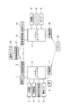
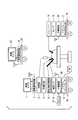
- FIG. 1 shows the configuration of the remote control system according to the present embodiment.
- the cart 10 includes an image monitor 1 for displaying endoscopic images and various control screens, a wireless communication device 2 for communicating image data and control data, an endoscope 3, an insufflation device 4, an ultrasonic processing device 5, An electric knife 6, a relay unit 7, a system controller 8 and a foot switch 9 are mounted. These devices on the cart 10 constitute an external device in the wireless communication system of the present invention.
- the cart 18 includes an image monitor 11 for displaying endoscopic images and various control screens, a wireless communication device 12 for communicating image data and control data, an endoscope 13, a shaver 14, a pump 15, a relay device 16, and a system A controller 17 is mounted. These devices on the cart 18 constitute an external device (first external device) in the wireless communication system of the present invention.
- the remote control 19 for remote control of each medical device is in the vicinity of the cart 18, and the signal from the remote control 19 is in a state of being transmitted only to the relay device 16 by infrared communication.
- the remote control 19 is in the vicinity of the cart 18 in FIG. 1, when the remote control 19 is in the vicinity of the cart 10, the signal from the remote control 19 is transmitted only to the relay device 7 on the cart 10.
- An image monitor 20 and a wireless communication device 21 are mounted on the cart 22, and the image monitor 20 displays an image received by the wireless communication device 21.
- These devices on the cart 22 constitute an external device (second external device) in the wireless communication system of the present invention.
- a patient 23 is placed on a patient bed 24 and a probe from a medical device such as an endoscope is attached.
- an endoscope, an insufflation apparatus, an ultrasonic processing apparatus, an electric scalpel, a shaver, and a pump are known medical apparatuses, and in the present embodiment, they are described as articles having known functions. Further explanation is omitted.
- the foot switch 9 is connected to the system controller 8 and controls the output of the ultrasonic processor 5 or the electric knife 6. By switching the operation state of the foot switch 9, the remote control 19 can switch which of the ultrasonic processing device 5 and the electric knife 6 is to be controlled.
- the wireless communication device the relay device, the system controller, and the remote control will be described later.
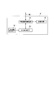
- FIG. 2 shows the connection relationship of each medical device that the remote control system has.
- each device (equipment) mounted on the cart 10 is connected to the system controller 8, and the system controller 8 grasps the operation state of each device.
- each device (equipment) mounted on the cart 18 is connected to the system controller 17, and the system controller 17 grasps the operation state of each device.
- FIG. 2 shows a state in which the signal output from the remote control 19 is transmitted only to the relay device 16.
- the relay device 7 grasps the operation state of each device mounted on the cart 10 based on the information from the system controller 8 and also uses the relay device 16 by wireless communication via the wireless communication device 2 and the wireless communication device 12. The information exchange is carried out, and the operation state of each device mounted on the cart 18 is also grasped.
- the relay device 16 grasps the operation state of each device mounted on the cart 18 based on the information from the system controller 17, and by wireless communication via the wireless communication device 2 and the wireless communication device 12. The information exchange with the relay device 7 is performed, and the operation state of each device mounted on the cart 10 is also grasped. The method of grasping the operation state of each device by these relay devices will be described in detail later with reference to FIGS. 5 to 11.
- the wireless communication device 2 of the cart 10, the wireless communication device 12 of the cart 18, and the wireless communication device 21 of the cart 22 perform wireless communication belonging to a predetermined radio wave band (frequency band). These wireless communication devices have an image communication function, and in FIG. 2, the wireless communication device 2 of the cart 10 and the wireless communication device 21 of the cart 22 perform wireless communication of image data. Also, the wireless communication device 2 of the cart 10 and the wireless communication device 12 of the cart 18 perform wireless communication of control data for controlling the operation of each device using an image communication function.
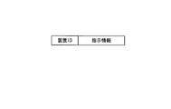
- FIG. 3 shows the structure of control data (control instruction) transmitted from the remote control 19.
- the control data includes an apparatus ID (ID information) indicating an ID of an apparatus to be controlled and instruction information indicating an instruction content (control content) for the apparatus to be controlled.
- ID information an apparatus ID
- instruction information indicating an instruction content (control content) for the apparatus to be controlled.
- FIG. 4 shows the configuration of the remote control 19.
- the remote control 19 includes an infrared light emitting element 27, a visible light receiving element 28, a communication interface circuit 30, a control button 26, a display element 25, a storage circuit 31, and a remote control control circuit 29.
- the infrared light emitting element 27 transmits control data by infrared communication. Since infrared rays are used, the communication between the remote control 19 and the relay devices 7 and 16 is not easily affected by the electromagnetic noise generated by the electric knife 6 or the like. In the embodiment of the present invention, an example is shown in which the remote control 19 performs infrared communication, but the communication performed by the remote control 19 may be close proximity communication (short distance communication) in which communication can be performed only in the vicinity of the relay device. Instead of infrared light, ultrasonic waves may be used.
- the visible light receiving element 28 receives the device ID of each device by optical communication through the image monitor. The reception of the device ID by the optical communication will be described in detail later with reference to FIG.
- the communication interface circuit 30 communicates using the infrared light emitting element 27 and the visible light receiving element 28.
- the control button 26 receives an operation input for instructing the operation of the remote control 19.
- the display element 25 displays the operation state of the remote control 19.
- the storage circuit 31 stores the device ID received by optical communication.
- the remote control control circuit 29 controls the overall operation of the remote control 19.
- the remote control circuit 29 interprets the instruction content to generate instruction information, and displays the result on the display element 25.
- the control data is generated by adding the device ID stored in the storage circuit 31 to the instruction information.
- the control data is transmitted by infrared light via the communication interface circuit 30 and the infrared light emitting element 27, and is received by a nearby relay device.
- FIG. 5 shows the configuration of the relay device 16.
- the relay device 16 includes an infrared light receiving element 32, an infrared interface circuit 33, a relay device control circuit 34, and a storage circuit 35.
- the infrared light receiving element 32 receives control data from the remote control 19 by infrared communication.
- the infrared interface circuit 33 processes the signal from the infrared light receiving element 32 and transmits it to the relay device control circuit 34.
- the relay device control circuit 34 controls the entire relay device 16.
- the storage circuit 35 includes a system state table indicating a list of the state of each device (equipment) on the cart 10 and the state of each device (machine) on the cart 18, and control data waiting for transmission to the relay device.
- a control data transmission waiting table indicating a list is stored.
- the relay device 7 is connected to the system controller 17 via the relay device input / output signal 36 from the relay device control circuit 34.
- the configuration of the relay device 7 is also the same as that of the relay device 16.
- the relay device 16 When the relay device 16 receives control data from the remote control 19, the relay device 16 notifies a system controller to which a device to be controlled is connected based on the device ID in the control data.
- the system controller having received the control command appropriately controls the target apparatus based on the control command.
- control instruction is an instruction for the shaver 14
- the relay device 16 directly controls the control instruction based on the received control data.
- the control command is a command to the insufflation device 4
- the insufflation device 4 is connected to the system controller 8 of the cart 10 on which the relay device 7 is placed.
- the control data is transmitted to the relay device 7 by communication, and the relay device 7 notifies the system controller 8 of a control command.
- FIG. 6 is an example of a system status table.
- the system status table is performed by grasping the operation status of the device on the cart in which the relay device in the remote control system is mounted, determination as to whether or not to transmit control data from the remote control 19 by wireless communication, and wireless communication Is a table used for determining the start timing of the
- the type of the device mounted on each cart, the device ID, the operation state, and the presence or absence of the electromagnetic noise generated during the device operation are recorded.
- the electric knife 6 mounted on the cart 10 is registered as device ID: SG-001, operating state: operating, electromagnetic noise generated at the time of device operation: present. This indicates that wireless communication of control data from the remote control 19 can not be performed because electromagnetic noise occurs when the electric knife 6 is in operation.
- FIG. 7 is an example of a control data transmission waiting table used by the relay device.
- the control data transmission waiting table is a table in which among control data received from the remote control 19, control data to be transmitted by wireless communication to a relay device of another cart is summarized.
- the ID of the relay device to be the transmission destination the type of the device to be controlled, the device ID, the control content, and the reception time based on the reception of control data are recorded.
- FIG. 7 shows an example in which an instruction to change the connection destination of the foot switch from the current electric knife 6 to the ultrasonic processing device 5 and an instruction to change the flow rate of the insufflation device 4 are registered. .
- the image of the endoscope 3 is in communication with the wireless communication device 21 connected to the image monitor 20 via the wireless communication device 2 and the wireless communication device 21, and the remote controller 19 is shown in FIG.
- the control contents (change of connection destination of foot switch, change of flow rate of insufflation device) are instructed to the relay device 16 and the electric knife 6 is in operation at first and then stopped as an example.
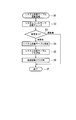
- FIG. 8 shows how control data is wirelessly transmitted in the above procedure.
- the electric knife 6 is in operation until time t6 and then stops.
- the wireless communication device 2 periodically transmits the image of the endoscope 3. For example, when one frame is composed of 60 images, the transfer cycle is 16.7 ms, and in the figure, the period from time t1 to t5 is 16.7 ms.
- a period of time t4 to t5 is a blanking period in which image data is not transmitted, and control data is wirelessly communicated using this period.
- the contents of the wireless communication may not be transmitted accurately. Since image data is transmitted continuously, it is acceptable even if the screen is disturbed by the influence of electromagnetic noise, but since errors in control data may cause serious problems, electromagnetic noise is generated. The wireless communication of control data is not performed during the period.
- control data indicating a control command (change in flow rate of the insufflation device) from the remote control 19 is transmitted to the relay device 16 in a period from time t2 to t3.
- the control data received by the relay device 16 is added to the control data transmission waiting table.
- new control is performed after control data indicating a change instruction of the connection destination of the foot switch instructed previously. Data is added.
- the relay device 16 controls the transmission timing of control data so that the wireless communication device 21 transmits control data in the blanking period after the electric knife 6 is stopped.
- FIGS. 9 to 11 are common to the relay device 7 and the relay device 16. Also, the processing shown in FIGS. 9 to 11 is performed by software under the control of the OS, and after the processing is completed, another software under the control of the OS is executed.
- FIG. 9 shows the system state table update process (S1).
- the relay device In the system status table update process (S1), the relay device periodically monitors the status of each device connected to the system controller via the system controller to which the relay device is connected, and updates the system status table. It is a process.
- the relay device control circuit 34 In the system state table update process (S1), the relay device control circuit 34 first checks the state of each device via the system controller (S2). Subsequently, the relay device control circuit 34 compares the contents of the system state table stored in the storage circuit 35 with the state of each device notified from the system controller (S3). If there is no change in the state of each device, the system state table update process (S1) ends (S7). If there is a change in the status of each device, the relay device control circuit 34 updates the system status table (S4), turns the system status table flag ON (S5), and turns the transmission activation flag ON (S6). The state table update process (S1) is ended (S7).
- the system state table flag is a flag indicating that the system state table has been updated
- the transmission activation flag is a flag that requests activation of the wireless transmission process (S8) described below.
- FIG. 10 shows the wireless transmission process (S8).
- the wireless transmission process (S8) is a process of transmitting the contents of the system state table and the control data transmission waiting table. If the transmission activation flag is ON, the wireless transmission process (S8) is activated, and if the system state table flag is ON, the system state table updated by the system state table update process (S1) is transmitted, and control data transmission is awaited. When the table flag is ON, the contents of the control data transmission waiting table are transmitted.
- the relay device control circuit 34 checks the system state table by the transmission environment check (S9), and determines whether transmission is possible. When the device registered as electromagnetic noise: Yes is operating, the relay device control circuit 34 determines that transmission is not possible and repeats the transmission environment check (S9). If the device registered as electromagnetic noise: present is not operating, the relay device control circuit 34 checks the system state table flag (S10). When the system status table flag is ON, the relay device control circuit 34 executes the system status table transmission process (S11) and the system status table flag OFF process (S12), and then checks the control data transmission wait table flag (S13). Run. When the system state table flag is OFF, the relay device control circuit 34 executes the control data transmission waiting table flag check (S13) as it is.
- the system state table updated by the system state table update process (S1) is transmitted.
- the relay device control circuit 34 outputs the system state table to the wireless communication device via the system controller, and the wireless communication device uses the next blanking period to perform another wireless communication Send the system status table to the device.
- the system status table received by the other wireless communication device is output to the relay device via the system controller.
- the relay device control circuit 34 updates the system state table stored in the storage circuit 35.
- the relay device control circuit 34 turns off the system state table flag (S12).
- the relay device control circuit 34 checks the control data transmission waiting table flag. When the control data transmission waiting table flag is ON, the relay device control circuit 34 executes control data transmission waiting table transmission processing (S14) and control data transmission waiting table flag OFF processing (S15), and thereafter, the transmission activation flag OFF processing Execute (S16).
- the relay device control circuit 34 In the control data transmission waiting table transmission process (S14), the relay device control circuit 34 outputs control data to the wireless communication device via the system controller, and the wireless communication device uses the next blanking period to transmit another wireless signal. Send control data to the communication device. After the control data transmission waiting table transmission processing (S14), the relay device control circuit 34 turns off the control data transmission waiting table flag and the transmission activation flag (S15, S16), and ends the wireless transmission processing (S8).
- the relay device control circuit 34 executes the transmission start flag OFF processing (S16) as it is. After the transmission activation flag OFF process (S16), the wireless transmission process (S8) ends (S17).
- FIG. 11 shows remote control data reception processing (S18).
- the remote control data reception process (S18) is a process performed when the control data from the remote control 19 is received.
- the relay device control circuit 34 starts remote control data reception processing (S18).
- the relay device control circuit 34 first receives control data (S19), and then performs wireless transmission execution determination (S20).
- the relay device control circuit 34 executes the device position determination (S24), and otherwise executes the update of the control data transmission waiting table (S21). It should be noted that the determination as to which relay device the communication from the remote control 19 has reached determines whether the operation status of all the relay devices in the system status table shown in FIG. 6 is "remote control connected". By doing.
- the relay device control circuit 34 determines the device to be controlled from the device ID in the control data. When the device to be controlled is in the same cart as itself, the relay device control circuit 34 executes control command notification (S25) to the system controller and ends remote control data reception processing (S18) (S26), otherwise In this case, the remote control data reception process (S18) is immediately ended (S26).
- the relay device control circuit 34 adds the control data received from the remote controller 19 to the control data transmission waiting table stored in the storage circuit 35. At this time, for control data that is control data for the same device and for which control content (for example, flow rate change of the insufflation device) is duplicated, only the latest control data is stored in the control data transmission wait table based on the acceptance time It is put.
- the relay device control circuit 34 After updating the control data transmission waiting table (S21), the relay device control circuit 34 turns on the control data transmission waiting table flag (S22), turns on the transmission activation flag (S23), and performs remote control data reception processing (S18). End (S26).
- the control command is notified to the system controller to which the device to be controlled is connected without performing wireless transmission. It will be.
- FIG. 12 shows a case where a screen for initial setting processing is displayed on the image monitor 20.
- the name of the device that performs remote control with the remote control 19 is shown for each cart, and the device ID of each device is transferred to the remote control 19 by visible light communication on the side thereof.
- An ID communication point 37 is disposed.
- the ID communication point 37 has a function of notifying the device ID by a change in brightness (flashing), and notifies the remote controller 19 of the device ID through the visible light receiving element 28 of the remote controller 19.
- Each device ID is collected by the relay device of each cart via the system controller and stored as part of the system status table. At the time of initialization, data of the device ID is extracted from the desired relay device.
- the display of the screen for initial setting processing can be performed by the image monitor 1 and the image monitor 11, in the present description, the case where the screen created by the system controller 8 is displayed on the image monitor 20 is taken as an example.
- the system controller 8 uses the device ID stored in the system status table of the relay device 7 to create a screen for initial setting processing.
- the created screen is displayed on the image monitor 20 via the wireless communication device 2 and the wireless communication device 21.
- a method used in the present embodiment to blink a part during monitoring and to transmit information by visible light communication due to a change in the blinking interval is known and thus detailed description will be omitted.
- the relay apparatus wirelessly transmits control data received from the remote control 19 by infrared communication using the wireless communication apparatus on its cart.
- Communication of control data can be favorably performed by transmitting control data at a good timing of a wireless communication condition without generation of electromagnetic noise.
- a control command is surely notified to a remote non-control device group A remote control system can be provided.
- the function of the relay device is mainly different from that of the first embodiment.
- the relay device of the present embodiment has a wireless communication function, and wireless communication is performed between the relay devices.
- the priority order is assigned to each medical device, and the processing in the relay device changes according to the priority order of the medical devices in operation at the time of receiving control data from the remote control 19.
- FIG. 13 shows the configuration of the remote control system according to the present embodiment.
- the configurations of the relay device and the cart 18 are different.
- the configuration of the cart 18 is a configuration in which the image monitor 11, the wireless communication device 12, and the endoscope 13 are deleted from the configuration shown in FIG.
- the wireless communication device since there is no wireless communication device 12 in the cart 18, the wireless communication device can not be used to transmit control data between relay devices as in the first embodiment. Therefore, the relay device 38 and the relay device 39 of the present system are equipped with a wireless communication function, and wireless communication is directly performed between the relay devices.
- FIG. 14 shows the configuration of the relay device 38 mounted on the cart 10.
- the wireless communication circuit 44 is connected to the relay device control circuit 42, and the antenna 46 is connected to the wireless communication circuit 44.
- the infrared light receiving element 40, the infrared interface circuit 41, the relay device control circuit 42, and the storage circuit 43 are the same as those described in the first embodiment, and thus the description thereof is omitted.
- the relay device 39 also has the same configuration. With the above configuration, wireless communication can be performed between the relay device 38 and the relay device 39.
- priority is assigned to each medical device in the remote control system. If a control instruction to a high priority device is issued from the remote control 19 during operation of a low priority device, wireless communication between relay devices is required, but the low priority device in operation is noisy. When it occurs and interferes with wireless communication, the operation state of a device with a lower priority is changed to create a wireless communicable condition, and wireless communication is performed between relay devices. If the priority order is the same, the device operating first becomes the priority, so the change of the operation state is not performed.
- FIG. 15 shows an example of the system status table of this embodiment.
- the priority of each device is added to the system state table described in the first embodiment.
- the priority of the system controller is the top priority 1, and so on, and so on, such as an electric knife: 2, an ultrasonic processing device: 3.
- the relay device of the present embodiment is not a control target by the remote control 19, priority is not assigned.
- the instruction to the system controller having the priority of 1 includes an instruction for various emergency processes (emergency stop etc.).
- the wireless signal accompanying the operation of the wireless communication device does not become noise, so the system status table The item of noise was "no".
- the wireless signal accompanying the operation of the wireless communication device is noise for wireless communication between the relay devices, the item of noise in the system state table is "presence".
- control data will be described with reference to FIG.
- the case where the remote controller 19 transmits control data for the shaver 14 to the relay device 38 will be described as an example using the configuration shown in FIG.
- the wireless communication device 2 is transmitting image data to the wireless communication device 21 and the operation state of the other devices is in the state shown in FIG.
- FIG. 16 is a timing chart of communication of control data in the above state.
- the relay device control circuit 42 of the relay device 38 determines the priority of the control target device corresponding to the device ID in the control data and the noise during operation of the system state table Compare the priority of the device generating the In this description, since control data is transmitted to the shaver 14, the priority "2" of the shaver 14 and the priority "7" of the wireless communication device 2 in operation are compared.
- the relay device 38 When the relay device 38 receives control data from the remote control 19 at the timing shown (time t2 to t3), the priority of the shaver 14 is higher than the priority of the wireless communication device 2, so the relay device control circuit of the relay device 38. 42 notifies the system controller 8 of an operation stop instruction of the wireless communication apparatus 2.
- the system controller 8 having received the notification stops the operation of the wireless communication device 2 (time t4). Thereby, the wireless communication of the image data which is originally performed until time t7 is stopped at time t4.
- the relay device control circuit 42 transmits control data to the relay device 39 via the wireless communication circuit 44 and the antenna 46 (time t5 to t6).
- the relay device control circuit 42 of the relay device 39 notifies the system controller 17 of a control command based on the received control data.
- the system controller 17 controls the shaver 14 based on the notified control command.
- the operation of the wireless communication device 2 is resumed (after time t8).
- control data from the remote control 19 is transmitted to the shaver 14 via the relay device 38 and the relay device 39.
- the initial setting process of the remote control 19 in the present embodiment is performed using data from a removable USB memory attached to the remote control 19.
- the setting of the device ID of each medical device in the remote control system to the USB memory is performed by attaching the USB memory to the relay device. Since a method of setting information via a USB memory is known, detailed description will be omitted.
- the relay apparatus when the relay apparatus wirelessly transmits control data received from the remote control 19 by infrared communication using its own wireless communication apparatus, the relay apparatus may not transmit other wireless communication or electromagnetic noise. Communication of control data can be favorably performed by transmitting the control data at a good timing of the wireless communication condition, which does not occur.
- control data to the device with high priority is transmitted from the remote control 19 and the relay device that receives the control data from the remote control 19 operates the device that generates a large amount of noise along with the operation If the priority of the device is lower than the priority of the medical device receiving the control command, it is possible to stop the active device to reduce noise before transmitting control data. For this reason, control data to a medical device with a high priority can be transmitted quickly and reliably.
- the present invention can be widely applied to a wireless communication device and a wireless communication system that perform wireless communication of control data for remotely controlling an external device. According to the present invention, communication of control data can be favorably performed in a wireless communication apparatus and a wireless communication system.
Abstract
La présente invention concerne un dispositif de communication sans fil comprenant : une unité de communication sans fil servant à exécuter des communications sans fil entre un premier dispositif externe et un deuxième dispositif externe en utilisant des ondes électromagnétiques d'une bande d'ondes électromagnétiques spécifiée ; une unité de communication de proximité servant à exécuter des communications de proximité avec un terminal de commande ; et un contrôleur servant à émettre des données de commande qui sont reçues du terminal de commande par l'intermédiaire de l'unité de communication de proximité et qui indiquent une instruction destinée au premier dispositif externe, ledit contrôleur ajustant les données de commande ou la chronologie d'émission des données de commande lorsque les données de commande sont envoyées au premier dispositif externe pendant que le premier dispositif externe ou l'unité de communication sans fil est en train d'envoyer séquentiellement des données au deuxième dispositif externe.
Priority Applications (3)
| Application Number | Priority Date | Filing Date | Title |
|---|---|---|---|
| CN201180053639.0A CN103202033B (zh) | 2010-11-10 | 2011-07-29 | 无线通信装置以及无线通信系统 |
| EP11840054.8A EP2627103B1 (fr) | 2010-11-10 | 2011-07-29 | Dispositif de communication sans fil et système de communication sans fil |
| US13/888,703 US9055394B2 (en) | 2010-11-10 | 2013-05-07 | Wireless communication device and wireless communication system |
Applications Claiming Priority (2)
| Application Number | Priority Date | Filing Date | Title |
|---|---|---|---|
| JP2010251969A JP5675283B2 (ja) | 2010-11-10 | 2010-11-10 | 無線通信装置 |
| JP2010-251969 | 2010-11-10 |
Related Child Applications (1)
| Application Number | Title | Priority Date | Filing Date |
|---|---|---|---|
| US13/888,703 Continuation US9055394B2 (en) | 2010-11-10 | 2013-05-07 | Wireless communication device and wireless communication system |
Publications (1)
| Publication Number | Publication Date |
|---|---|
| WO2012063531A1 true WO2012063531A1 (fr) | 2012-05-18 |
Family
ID=46050689
Family Applications (1)
| Application Number | Title | Priority Date | Filing Date |
|---|---|---|---|
| PCT/JP2011/067434 WO2012063531A1 (fr) | 2010-11-10 | 2011-07-29 | Dispositif de communication sans fil et système de communication sans fil |
Country Status (5)
| Country | Link |
|---|---|
| US (1) | US9055394B2 (fr) |
| EP (1) | EP2627103B1 (fr) |
| JP (1) | JP5675283B2 (fr) |
| CN (1) | CN103202033B (fr) |
| WO (1) | WO2012063531A1 (fr) |
Cited By (1)
| Publication number | Priority date | Publication date | Assignee | Title |
|---|---|---|---|---|
| JP2019520907A (ja) * | 2016-06-30 | 2019-07-25 | フレゼニウス メディカル ケア ドイッチェランド ゲゼルシャフト ミット ベシュレンクテル ハフツング | 複数の透析装置の専用遠隔制御 |
Families Citing this family (6)
| Publication number | Priority date | Publication date | Assignee | Title |
|---|---|---|---|---|
| JP6423172B2 (ja) * | 2014-05-22 | 2018-11-14 | オリンパス株式会社 | 無線内視鏡システム、表示装置、及びプログラム |
| CN114098599A (zh) * | 2015-09-17 | 2022-03-01 | 恩达马斯特有限公司 | 内窥镜系统 |
| TWI613623B (zh) * | 2015-11-06 | 2018-02-01 | 財團法人資訊工業策進會 | 智慧遙控器、電子裝置控制系統以及電子裝置控制方法 |
| CN105320043A (zh) * | 2015-11-30 | 2016-02-10 | 深圳市鹏瑞智能技术应用研究院 | 一种远程控制方法、终端及系统 |
| JP7051408B2 (ja) | 2017-12-07 | 2022-04-11 | ソニー・オリンパスメディカルソリューションズ株式会社 | 医療用内視鏡装置、および医療用観察システム |
| EP3876239A1 (fr) | 2020-03-03 | 2021-09-08 | W & H Dentalwerk Bürmoos GmbH | Procédé de transmission sans fil de données dans un système médical ou dentaire ainsi qu'un tel système médical ou dentaire |
Citations (5)
| Publication number | Priority date | Publication date | Assignee | Title |
|---|---|---|---|---|
| JPH07147697A (ja) | 1993-11-25 | 1995-06-06 | Hitachi Ltd | リモコン装置 |
| JP2003245286A (ja) | 2002-02-22 | 2003-09-02 | Olympus Optical Co Ltd | 内視鏡手術システム |
| JP2008519501A (ja) | 2004-11-01 | 2008-06-05 | ストライカー・コーポレーション | 中央ユニットへの無線制御の安全な送信 |
| JP2008301249A (ja) * | 2007-05-31 | 2008-12-11 | Toshiba Corp | 映像処理装置及び映像処理方法 |
| JP2010074204A (ja) * | 2008-09-16 | 2010-04-02 | Hitachi Ltd | 無線映像送信装置、無線映像受信装置、無線通信システム、及びそれに用いられるcecメッセージ伝送方法 |
Family Cites Families (4)
| Publication number | Priority date | Publication date | Assignee | Title |
|---|---|---|---|---|
| JP3454136B2 (ja) * | 1998-02-23 | 2003-10-06 | ソニー株式会社 | 無線伝送方法 |
| JP2002232978A (ja) * | 2001-02-07 | 2002-08-16 | Hitachi Ltd | ネットワーク上の機器を制御するためのリモコン装置、変換器、及び制御システム |
| JP4176011B2 (ja) * | 2001-07-10 | 2008-11-05 | シャープ株式会社 | Avデータ送信装置、avデータ受信装置、avデータ表示・再生装置 |
| JP5067893B2 (ja) * | 2009-03-12 | 2012-11-07 | 日本電信電話株式会社 | 機器操作システムおよび方法 |
-
2010
- 2010-11-10 JP JP2010251969A patent/JP5675283B2/ja not_active Expired - Fee Related
-
2011
- 2011-07-29 CN CN201180053639.0A patent/CN103202033B/zh active Active
- 2011-07-29 EP EP11840054.8A patent/EP2627103B1/fr not_active Not-in-force
- 2011-07-29 WO PCT/JP2011/067434 patent/WO2012063531A1/fr active Application Filing
-
2013
- 2013-05-07 US US13/888,703 patent/US9055394B2/en active Active
Patent Citations (5)
| Publication number | Priority date | Publication date | Assignee | Title |
|---|---|---|---|---|
| JPH07147697A (ja) | 1993-11-25 | 1995-06-06 | Hitachi Ltd | リモコン装置 |
| JP2003245286A (ja) | 2002-02-22 | 2003-09-02 | Olympus Optical Co Ltd | 内視鏡手術システム |
| JP2008519501A (ja) | 2004-11-01 | 2008-06-05 | ストライカー・コーポレーション | 中央ユニットへの無線制御の安全な送信 |
| JP2008301249A (ja) * | 2007-05-31 | 2008-12-11 | Toshiba Corp | 映像処理装置及び映像処理方法 |
| JP2010074204A (ja) * | 2008-09-16 | 2010-04-02 | Hitachi Ltd | 無線映像送信装置、無線映像受信装置、無線通信システム、及びそれに用いられるcecメッセージ伝送方法 |
Non-Patent Citations (1)
| Title |
|---|
| See also references of EP2627103A4 |
Cited By (1)
| Publication number | Priority date | Publication date | Assignee | Title |
|---|---|---|---|---|
| JP2019520907A (ja) * | 2016-06-30 | 2019-07-25 | フレゼニウス メディカル ケア ドイッチェランド ゲゼルシャフト ミット ベシュレンクテル ハフツング | 複数の透析装置の専用遠隔制御 |
Also Published As
| Publication number | Publication date |
|---|---|
| CN103202033B (zh) | 2016-10-19 |
| EP2627103B1 (fr) | 2015-02-18 |
| CN103202033A (zh) | 2013-07-10 |
| JP5675283B2 (ja) | 2015-02-25 |
| JP2012105073A (ja) | 2012-05-31 |
| US9055394B2 (en) | 2015-06-09 |
| EP2627103A4 (fr) | 2014-01-08 |
| EP2627103A1 (fr) | 2013-08-14 |
| US20130244580A1 (en) | 2013-09-19 |
Similar Documents
| Publication | Publication Date | Title |
|---|---|---|
| WO2012063531A1 (fr) | Dispositif de communication sans fil et système de communication sans fil | |
| JP5542246B1 (ja) | 医療用制御システム | |
| JP4643510B2 (ja) | 手術システム制御装置及び手術機器のタイムアウト値設定方法 | |
| US8380126B1 (en) | Reliable communications for wireless devices | |
| JP2007527166A (ja) | 無線医療監視方法及び関連のシステム並びに患者監視装置 | |
| WO2013035384A1 (fr) | Système de transmission vidéo sans fil et dispositif de transmission | |
| JP2008263308A (ja) | リモートコントローラ、電子機器および遠隔操作システム | |
| JP2009207872A (ja) | 医療制御装置及び該システム | |
| JP6935824B2 (ja) | 要看介護者監視システム | |
| JP5893804B2 (ja) | 無線画像伝送システム及び無線画像伝送方法 | |
| JP2013109212A (ja) | カメラシステム、通信装置及びその制御方法、並びにプログラム | |
| JP5816524B2 (ja) | ワイヤレス内視鏡システム | |
| EP2921101B1 (fr) | Dispositif de terminal et système de télémétrie | |
| JP2013183948A (ja) | 医療画像送信システム、送信装置及び受信装置 | |
| WO2017141441A1 (fr) | Système de commande sans fil | |
| JP2003256030A (ja) | 制御システム | |
| WO2020067339A1 (fr) | Dispositif de commande à distance et système de commande à distance | |
| JP6429974B2 (ja) | X線撮像装置 | |
| TW201545721A (zh) | 具有遠端操控裝置之x光機設備 |
Legal Events
| Date | Code | Title | Description |
|---|---|---|---|
| 121 | Ep: the epo has been informed by wipo that ep was designated in this application |
Ref document number: 11840054 Country of ref document: EP Kind code of ref document: A1 |
|
| WWE | Wipo information: entry into national phase |
Ref document number: 2011840054 Country of ref document: EP |
|
| NENP | Non-entry into the national phase |
Ref country code: DE |