WO2012060269A1 - 画像処理方法、画像処理装置及び撮像装置 - Google Patents
画像処理方法、画像処理装置及び撮像装置 Download PDFInfo
- Publication number
- WO2012060269A1 WO2012060269A1 PCT/JP2011/074750 JP2011074750W WO2012060269A1 WO 2012060269 A1 WO2012060269 A1 WO 2012060269A1 JP 2011074750 W JP2011074750 W JP 2011074750W WO 2012060269 A1 WO2012060269 A1 WO 2012060269A1
- Authority
- WO
- WIPO (PCT)
- Prior art keywords
- coordinates
- virtual projection
- reference plane
- projection plane
- coordinate system
- Prior art date
- Legal status (The legal status is an assumption and is not a legal conclusion. Google has not performed a legal analysis and makes no representation as to the accuracy of the status listed.)
- Ceased
Links
Images






Classifications
-
- G—PHYSICS
- G06—COMPUTING OR CALCULATING; COUNTING
- G06T—IMAGE DATA PROCESSING OR GENERATION, IN GENERAL
- G06T5/00—Image enhancement or restoration
- G06T5/80—Geometric correction
-
- H—ELECTRICITY
- H04—ELECTRIC COMMUNICATION TECHNIQUE
- H04N—PICTORIAL COMMUNICATION, e.g. TELEVISION
- H04N23/00—Cameras or camera modules comprising electronic image sensors; Control thereof
- H04N23/80—Camera processing pipelines; Components thereof
- H04N23/81—Camera processing pipelines; Components thereof for suppressing or minimising disturbance in the image signal generation
-
- H—ELECTRICITY
- H04—ELECTRIC COMMUNICATION TECHNIQUE
- H04N—PICTORIAL COMMUNICATION, e.g. TELEVISION
- H04N23/00—Cameras or camera modules comprising electronic image sensors; Control thereof
- H04N23/60—Control of cameras or camera modules
- H04N23/698—Control of cameras or camera modules for achieving an enlarged field of view, e.g. panoramic image capture
-
- H—ELECTRICITY
- H04—ELECTRIC COMMUNICATION TECHNIQUE
- H04N—PICTORIAL COMMUNICATION, e.g. TELEVISION
- H04N25/00—Circuitry of solid-state image sensors [SSIS]; Control thereof
- H04N25/60—Noise processing, e.g. detecting, correcting, reducing or removing noise
- H04N25/61—Noise processing, e.g. detecting, correcting, reducing or removing noise the noise originating only from the lens unit, e.g. flare, shading, vignetting or "cos4"
Definitions
- the present invention relates to an image processing method, an image processing apparatus, and an imaging apparatus that perform distortion correction processing on an image captured by an imaging device via an optical system including a condenser lens.
- Patent Document 1 discloses a correction method of the prior art that corrects distortion generated in a captured image captured using a lens with a short focal length using a lens correction parameter.
- Patent Document 2 it is necessary to use an external information processing device to calculate the optical distortion correction parameter for each lens position from the wide end to the tele end of the optical zoom mechanism by using an interpolation operation.
- the optical distortion correction parameter for the discrete lens position within the range to perform the optical zoom the lens position at the time of zooming is limited to the lens position having the optical distortion correction parameter.
- the optical zoom between the positions is connected by electronic zoom.
- Patent Document 1 when a captured image obtained by a lens is linearly corrected, an image is enlarged in the peripheral portion as compared with the central portion, so that the image is deformed and is difficult to see. Corrections to prevent this include cylindrical distortion correction and spherical distortion correction.
- the processing time becomes long, the circuit scale increases, and the cost increases. There was a problem that increased.
- Patent Document 1 since the input image is corrected using the correction parameters, there is a possibility that the resolution is lowered when the image on the end side deviating from the center of the input image is cut out. Yes, the viewpoint conversion such as panning and tilting is insufficient.
- distortion correction parameters are set so as to correspond to changes in the optical parameters of the optical zoom and the diaphragm, and are not intended for viewpoint conversion, and are not compatible with real-time display.
- a new process is added each time a process such as zoom, pan, or tilt is added based on an instruction to change the shooting area by the user.
- Image processing is required, and when the image processing apparatus is implemented as hardware, the processing time becomes long, the circuit scale increases, and the cost may increase.
- the present invention provides an image processing method, an image processing apparatus, and an imaging apparatus capable of obtaining an output image with high visibility while reducing processing time with a relatively small circuit.
- the purpose is to provide.
- Have Reference plane system coordinates x d y d z d with respect to the reference plane are set, and z d coordinates in a direction perpendicular to the reference plane with respect to x d coordinates and y d coordinates
- a two-dimensional LUT to be used can be selected from a plurality of two-dimensional LUTs corresponding to a plurality of differently shaped virtual projection planes, The image processing method according to any one of claims 1 to 3, wherein the selected two-dimensional LUT is used in the second step.
- An image processing apparatus for obtaining image data that has been subjected to distortion correction processing using a plurality of pixel data obtained by receiving an image sensor having a plurality of pixels via an optical system, A coordinate in the world coordinate system of each pixel of the virtual projection plane is calculated based on a reference plane that is set in position and size and always has a fixed positional relationship with the virtual projection plane, and the calculated coordinates are An image processing unit that converts to a camera coordinate system using a distortion correction coefficient, calculates image data of the virtual projection plane based on the coordinates converted to the camera coordinate system and the plurality of pixel data; Reference plane system coordinates x d y d z d with respect to the reference plane are set, and z d coordinates in a direction perpendicular to the reference plane with respect to x d coordinates and y d coordinates on the reference plane are stored. A storage unit that stores a two-dimensional LUT based on the shape of the virtual projection plane, The image processing apparatus, wherein the image processing unit calculates coordinate
- the storage unit stores a plurality of two-dimensional LUTs corresponding to a plurality of differently shaped virtual projection planes
- the image processing unit calculates coordinates in the world coordinate system of each pixel of the virtual projection plane based on a two-dimensional LUT selected from the plurality of two-dimensional LUTs.
- An imaging device having a plurality of pixels; A setting unit for setting the position and size in the world coordinate system of the reference plane that is always in a fixed positional relationship with the virtual projection plane; Calculate coordinates in the world coordinate system of each pixel of the virtual projection plane based on the reference plane set by the setting unit, and convert the calculated coordinates into a camera coordinate system using a distortion correction coefficient of the optical system.
- An image processing unit that calculates image data on the virtual projection plane based on coordinates converted into the camera coordinate system and pixel data obtained from the plurality of pixels, and reference plane system coordinates based on the reference plane x d y d z d is set, and a two-dimensional LUT based on the shape of the virtual projection plane storing z d coordinates in a direction perpendicular to the reference plane with respect to x d coordinates and y d coordinates on the reference plane is obtained.
- a storage unit for storing, The image processing unit calculates coordinates in a world coordinate system of each pixel of the virtual projection plane based on the two-dimensional LUT.
- the storage unit stores a plurality of two-dimensional LUTs corresponding to a plurality of differently shaped virtual projection planes
- the image processing unit calculates coordinates in the world coordinate system of each pixel of the virtual projection plane based on the two-dimensional LUT selected by the setting unit from the plurality of two-dimensional LUTs.
- the imaging device according to any one of 9 to 11.
- a virtual projection of a set free shape is calculated by calculating coordinates in the world coordinate system of each pixel of the virtual projection surface using a two-dimensional LUT corresponding to the virtual projection surface of a free shape.
- a surface can be used.
- FIG. 1 It is a schematic diagram explaining the distortion correction which concerns on this embodiment. It is a figure which shows the shape of the virtual projection surface VP shown in FIG. 1, (a) is a front view, (b) is a top view, (c) is a side view. It is a figure which shows the example which moved the position of the virtual projection surface VP. It is a block diagram which shows schematic structure of an imaging device. It is a figure which shows the control flow of this embodiment. It is a schematic diagram explaining the reference plane DP. It is a schematic diagram which shows the relationship between virtual projection surface VP and reference plane DP. It is a figure explaining the coordinate of the virtual projection surface VP.
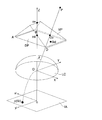
- FIG. 1 is a schematic diagram for explaining distortion correction according to the present embodiment.
- X, Y, and Z are world coordinate systems, and the origin O is the lens center.
- Z includes the optical axis, and the XY plane includes the lens center plane LC passing through the lens center O.
- Point P is an object point of the object in the world coordinate system XYZ.
- ⁇ is an incident angle with respect to the optical axis (coincident with the Z axis).
- x i and y i are camera coordinate systems, and the x i y i plane corresponds to the image sensor surface IA.
- o is the center of the image and is the intersection of the optical axis Z and the image sensor surface.
- the point p is a point on the image sensor surface in the camera coordinate system (corresponding to an imaging point), and the object point P is a camera using a distortion correction coefficient based on a parameter based on lens characteristics (hereinafter referred to as “lens parameter”). It is converted to the coordinate system.
- the VP is a virtual projection plane, which is a free-form surface.
- the virtual projection plane VP is set on the opposite side of the imaging element (and imaging element surface IA) with respect to the lens position (lens center plane LC) of the optical system.
- the reference plane DP can be changed in shape, size, and position in the world coordinate system based on an instruction from the user to the operation unit 130 (see FIG. 3).
- DP is a two-dimensional reference plane, and always has a fixed positional relationship with the virtual projection plane VP, and the positional relationship is reflected in a two-dimensional LUT described later.
- the size of the virtual projection plane VP is changed along with the size change of the reference plane DP, and the position of the virtual projection plane VP is changed along with the position change of the reference plane DP.
- x d, y d, z d is the reference plane coordinate system
- x d y d plane corresponds to the reference plane DP
- z d axis is the axis perpendicular to the reference plane.
- the center of the reference plane DP and the virtual projection plane VP coincides with the optical axis Z, and the reference plane DP is parallel to the XY plane of the world coordinate system. It is.
- position change means not only the case where the reference plane DP and the virtual projection plane VP are translated on the XY plane (corresponding to a translation vector), but also an angle change (also referred to as a posture change) to the rotation vector. This concept also includes
- “Cylindrical distortion correction” is to perform distortion correction using a virtual projection plane VP having a shape obtained by cutting a cylinder along a plane parallel to the axial direction.
- the virtual projection plane VP is an x d coordinate (or a reference plane DP). If the y d coordinate) can be specified, the z d coordinate can be specified.
- Trihedral mirror distortion correction is a shape in which three planes are continuous, a main mirror portion parallel to a reference plane DP arranged in the center, and two sides connected to this at a predetermined angle on both sides of the main mirror portion. Distortion correction is performed using a virtual projection plane VP having a shape including a side mirror.
- the virtual projection plane VP can specify the z d coordinate if the x d coordinate (or y d coordinate) of the reference plane DP can be specified.
- Spherical distortion correction is a shape in which the inner surface of a sphere is cut out into a rectangle.
- the virtual projection plane VP can specify the z d coordinate if the distance from the center of the reference plane DP can be specified.
- Free-form correction is a distortion correction method performed using a free-form virtual projection plane VP.
- a free shape is a shape other than a curved surface (cylinder, sphere) or a plane (trihedral mirror, mere plane) that can be expressed by an elementary function.
- the virtual projection plane VP is a shape in which the z d coordinate can be specified by specifying both the x d coordinate and the y d coordinate instead of one.
- a “free curved surface” is a shape that is a free shape and is configured by a curved surface other than a curved surface (cylinder, sphere) that can be expressed by an elementary function.
- FIG. 2 is a diagram showing the shape of the virtual projection plane VP shown in FIG. 2A is a front view, FIG. 2B is a top view, and FIG. 2C is a side view.
- the reference plane DP is not shown.
- the free shape shown in FIG. 2 is such a shape that the triangular prism is cut as a virtual projection plane VP by a plane that is not parallel to the bottom surface.
- the shape of the virtual projection plane VP can be changed by setting the lengths l X , l Y1 , l Y2 and l Z shown in FIG. As the shape is changed, a two-dimensional LUT describing a free shape described later is recalculated and updated.
- the shape of the virtual projection plane is not limited to this, and the shape of the inner surface of a hemisphere or a crown that is notched at a plane intersecting the sphere or the shape of the inner surface of the sphere cut into a rectangle may be used. Good. Moreover, the shape which connected the some surface like the shape of a triple mirror which consists of three continuous panels may be sufficient, or the shape which cut
- the virtual projection plane VP has a predetermined shape and size, and the center ov of the virtual projection plane VP and the center od of the reference plane DP are located on the Z axis.
- Gv is a point where the object point P is projected onto the virtual projection plane VP, and is an intersection of the object point P and a straight line passing through the lens center O and the virtual projection plane VP.
- Gd is a point where Gv is projected onto the reference plane DP.
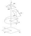
- FIG. 3 shows an example in which the positions of the reference plane DP and the virtual projection plane VP are moved based on the input of the operation unit 130 described later.
- the virtual projection plane VP0 and the reference plane DP0 indicate before movement, and the virtual projection plane VP1 and the reference plane DP1 indicate after movement. In the figure, they are rotated on the XZ plane in the world coordinate system.
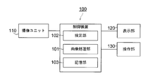
- FIG. 4 is a block diagram illustrating a schematic configuration of the imaging apparatus.
- the imaging apparatus includes an imaging unit 110, a control device 100, a display unit 120, and an operation unit 130.
- the imaging unit 110 includes a short-focus lens, an imaging element, and the like.
- examples of the lens include a wide-angle lens and a fisheye lens.
- the control device 100 includes an image processing unit 101, a setting unit 102, and a storage unit 103.
- the setting unit 102 sets the shape, position, and size of the reference plane DP based on an input instruction to the operation unit 130.
- the image processing unit 101 calculates the coordinates of the world coordinate system of each pixel of the virtual projection plane VP based on the setting of the shape, position, and size of the reference plane DP and the two-dimensional LUT corresponding to the shape of the virtual projection plane VP.
- a conversion table of the calculated coordinates into the camera coordinate system is created, and pixel data captured by the imaging unit 110 is processed using the conversion table to generate image data to be displayed on the display unit 120.
- the storage unit 103 stores a distortion correction coefficient calculated based on the lens parameters of the lens and a two-dimensional LUT based on the shape of the virtual projection plane VP. Also, the position and size of the reference plane DP and the created conversion table are stored. Furthermore, in addition to the virtual projection surface having the shape shown in FIG. 2 and the like, when using a plurality of virtual projection surfaces having different shapes such as other virtual projection surfaces (FIG. 11 and the like) described later, It is also possible to store a plurality of two-dimensional LUTs corresponding to this. In this case, the setting unit may select a two-dimensional LUT to be used from among a plurality of two-dimensional LUTs according to the type of use or a user input instruction to the operation unit 130. Examples of types of applications include surveillance cameras and in-vehicle back monitors.
- the display unit 120 includes a display screen such as a liquid crystal display, and sequentially displays the image data created by the image processing unit 101 based on the pixel data captured by the imaging unit 110 on the display screen.
- the operation unit 130 includes a keyboard, a mouse, or a touch panel arranged so as to be superimposed on the liquid crystal display of the display unit, and accepts user input operations.
- FIG. 5 is a diagram showing a control flow of the present embodiment.
- the set distortion correction conditions are input.
- the distortion correction condition (including viewpoint conversion) is set by setting the position and size of the reference plane DP in the world coordinate system by the setting unit 102 in accordance with an input instruction to the operation unit 130 by the user as described above.
- an image signal is input from the imaging unit 110, and an input image is obtained at a frame rate of 60 fps, for example.
- FIG. 6 is a schematic diagram illustrating the reference plane DP.
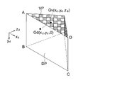
- FIG. 7 is a schematic diagram showing the positional relationship between the virtual projection plane VP and the reference plane DP.
- the reference plane DP is located on the x d y d plane of the reference plane coordinate system (x d y d z d ), and the virtual projection plane VP is vertically projected using the x d y d plane as a projection plane.
- the region of the reference plane DP is set so as to include the region of the projection view. As shown in FIG. 6, point A (0, 0, 0), point B (0, 495, 0), point C (655, 495, 0), point D of the reference plane DP in the reference plane coordinate system.
- a plane surrounded by (655, 0, 0) is divided into 656 ⁇ 496 pixel pixels Gd (total number of pixels: 325,000) at equal intervals.
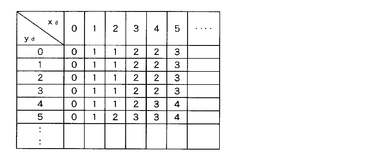
- Table 1 is an example of a two-dimensional LUT that outputs a zd coordinate in response to an input of a coordinate x d and a coordinate y d .
- the coordinates (x d , y) of the corresponding pixel Gv on the virtual projection plane VP with reference to the two-dimensional LUT for deriving z d by referring to the coordinates of x d , y d as shown in Table 1 from all the pixels Gd d , z d ) is calculated. Note that the total number of pixels is merely an example, and other values may be set.
- Pixel Gd on the reference plane DP as shown in FIG. 7, both the x d and y d matches since a relation obtained by projecting the pixel Gv on the virtual projection plane VP to the reference plane DP.
- the two-dimensional LUT stores coordinates z d with respect to the coordinates x d and y d based on the shape of the virtual projection plane VP, and the coordinates z d of the pixel Gv based on the coordinates x d and y d of the pixel Gd. Is calculated, the position of the coordinates (x d , y d , z d ) of the pixel Gv can be derived. This is performed for all the pixels Gd. The above is step S13.
- step S14 the coordinates of the pixel Gv calculated in step S13 are converted from the reference plane coordinate system (x d , y d , z d ) to the world coordinate system (X, Y, Z). This is performed based on setting information for changing the position of the reference plane DP.
- step S15 the distortion correction coefficient determined based on the lens parameters of the imaging unit 110 stored in the storage unit 103 is read.
- step S16 an LUT is generated that uses the coordinates of the virtual projection plane VP set using the distortion correction coefficient acquired in step S15 to convert the world coordinate system to the camera coordinate system (w2c conversion).
- the LUT is generated based on the coordinates of each pixel Gv in the world coordinate system and the distortion correction coefficient acquired in step S15, and the pixel Gi (x ′, y ′) in the corresponding camera coordinate system on the image sensor surface IA. This is done by calculating FIG. 8 is a schematic diagram showing the relationship between the image height h and the incident angle ⁇ .
- the image height (distance from the optical axis Z) of the subject (object point P) on the image sensor surface IA is determined by the incident angle ⁇ and the distortion correction coefficient.
- pi is the imaging position of the object point P on the image sensor surface IA when there is no distortion correction, and the imaging position after distortion correction is Gi.
- the coordinates of each pixel on the virtual projection plane are converted from the reference coordinate system to the camera coordinate system via the world coordinate system. That is, based on the lens data, coordinate conversion was performed to apply to which coordinate position of the camera coordinate the position of the reference coordinate system corresponds. At this time, distortion correction and viewpoint conversion such as rotation, translation, enlargement, reduction, etc. are performed together with the calculation of the position of the virtual projection plane VP.
- step S21 image generation is performed on the input image input in step S12 using the LUT referenced in step S21.
- image generation method there is a four-point interpolation as described below.
- the pixel of the image sensor to be referred to is determined from the coordinates (x i ′, y i ′) of the camera coordinate system of the pixel Gi shown in FIGS. Coordinates (x i, y i) of each pixel of the image sensor during the x i in, y i is an integer, step S16 of the LUT generation process pixels used in Gi (x i ', y i ') of x i ′ and y i ′ are not limited to integers and can take real values having a fractional part.
- the pixel data of the pixel of the corresponding image sensor is used as the virtual projection plane. It can be used as pixel data of an output image corresponding to the pixel Gv (X, Y, Z) on the VP.
- x i ′ and y i ′ are not integers and x i ′ and y i ′ do not match x i and y i , four-point interpolation is performed as pixel data of the output image corresponding to the pixel Gv.
- step S22 output processing is performed based on the generated image.
- an output process in the demosaic process, an output image can be obtained by calculating BGR data of each pixel from a signal of a peripheral pixel.
- the demosaic process is, for example, an image sensor composed of pixels arranged in a Bayer array, so that each pixel has only color information for one color, and interpolation processing is performed from information on neighboring pixels to obtain the color for three colors. It is to calculate color information.
- step S23 the generated output image is output to the display unit 120, for example, at a frame rate of 30 fps or 60 fps, and the process ends.
- This control flow is an example in which the virtual projection plane VP has a fixed shape and one type of two-dimensional LUT corresponding to the virtual projection plane VP is used.
- the present invention is not limited to this, and a plurality of different types corresponding to the type of application are used as a modification.
- a virtual projection plane VP having a shape may be used.
- a two-dimensional LUT to be used is selected from a plurality of two-dimensional LUTs corresponding to each of the plurality of virtual projection planes in step S11, and the control of step S13 is performed using the selected two-dimensional LUT.
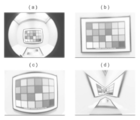
- FIG. 9 shows an example of an input image and an output image after distortion correction processing.
- FIG. 9A shows an input image.
- FIG. 9B is an example of an output image obtained in the setting of the planar virtual projection plane VP (equivalent to the reference plane DP in FIG. 1).
- FIG. 9C is an example of an output image obtained in setting the cylindrical virtual projection plane VP.
- FIG. 9D is an example of an output image obtained in setting the free-form virtual projection plane VP as shown in FIGS.
- the display range near the lower side (near side) is wide, and it is possible to recognize an area outside the display range on the planar or cylindrical virtual projection plane VP. It becomes.
- FIG. 10 is a diagram for explaining the correspondence between the reference plane DP and the two-dimensional LUT lattice point data according to another embodiment.
- z d coordinate data of the virtual projection plane VP related to each lattice point gp is stored in the two-dimensional LUT.
- the grid points gp are arranged so as to jump out at a predetermined cycle with respect to the pixel Gd.
- the grid point gp at the point A (0, 0, 0) on the reference plane DP is used as a reference. They are arranged with a period of 32 pixels in each of the x d and y d directions.
- the area covered by the block has a size equal to or larger than the reference plane DP.
- the size of the reference plane DP is not an integral multiple of the period 32 pixels of the lattice point gp, the area (672 ⁇ 512 pixels) covered by the block is larger than the size of the reference plane DP (656 ⁇ 496 pixels). It is also bigger.
- the z d coordinate of the pixel Gv on the virtual projection plane VP is obtained by referring to the two-dimensional LUT of the lattice point gp.
- the zd coordinate of the lattice point gp at the block 4 corner is obtained by referring to the two-dimensional LUT, and the z d coordinate of the obtained lattice point gp is linearly interpolated to obtain the pixel Find the z d coordinate of Gd.
- the z d coordinate of the virtual projection plane VP corresponding to the lattice points gp1, gp2, gp3, and gp4 at the four corners is obtained with reference to the two-dimensional LUT, and the z
- the z d coordinate of the pixel Gv on the virtual projection plane VP corresponding to the pixel Gd1 can be obtained.
- the data size of the two-dimensional LUT can be reduced by providing the two-dimensional LUT for all the pixels on the reference plane DP and using the thinned-out thinned data in the form of lattice points.
- FIG. 11A is a front view
- FIG. 11B is a top view
- FIG. 11C is a side view
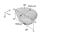
- FIG. 12 is a schematic diagram showing the relationship between the virtual projection plane VP and the reference plane DP.
- the virtual projection plane VP shown in the figure is a shape formed by a free-form surface.
- a free-form surface is a curved surface other than a curved surface (cylinder, sphere) that can be expressed by an elementary function.
- the bowl is cut into half vertical. Even for a complicated shape formed by such a free-form surface, the coordinates on the virtual projection plane VP can be specified by the two-dimensional LUT.
- FIG. 13 is an example of an output image obtained in the setting of the bowl-shaped virtual projection plane VP shown in FIGS.
- the bowl-shaped virtual projection plane VP shown as an example of the free shape the display range in the lower vicinity (near side) is wide, and the planar or cylindrical virtual projection plane VP is out of the display range. It becomes possible to recognize the area.
- Control apparatus 101 Image processing part 102 Setting part 103 Storage part 110 Imaging unit 120 Display part 130 Operation part VP Virtual projection plane DP Reference plane Gd Pixel on reference plane GV Pixel on virtual projection plane LC Lens center plane IA Image sensor surface O Lens center o Image center Gd Pixel on reference plane GV Pixel on virtual projection plane
Landscapes
- Engineering & Computer Science (AREA)
- Physics & Mathematics (AREA)
- Multimedia (AREA)
- Signal Processing (AREA)
- General Physics & Mathematics (AREA)
- Theoretical Computer Science (AREA)
- Image Processing (AREA)
- Editing Of Facsimile Originals (AREA)
- Studio Devices (AREA)
- Geometry (AREA)
Abstract
Description
仮想投影面と常に一定の位置関係となる基準平面のワールド座標系における位置及びサイズを、ユーザーの指示に基づいて設定する第1ステップと、
前記第1ステップで設定された基準平面に基づいて前記仮想投影面の各画素のワールド座標系における座標を算出し、前記算出した座標を前記光学系の歪み補正係数を用いてカメラ座標系に変換する第2ステップと、
前記複数の画素データと前記第2ステップで変換したカメラ座標系における座標とに基づいて、前記仮想投影面の画像データを算出する第3ステップと、
を有し、
前記基準平面を基準とする基準平面系座標xdydzdが設定され、前記基準平面上のxd座標、yd座標に対する、前記基準平面に垂直な方向のzd座標を格納した前記仮想投影面の形状に基づく2次元LUTを有し、
前記第2ステップでは、前記2次元LUTに基づいて前記仮想投影面の各画素のワールド座標系における座標を算出することを特徴とする画像処理方法。
前記選択した2次元LUTを前記第2ステップで使用することを特徴とする前記1乃至3の何れか一項に記載の画像処理方法。
位置及びサイズが設定された基準平面であって仮想投影面と常に一定の位置関係となる基準平面に基づいて前記仮想投影面の各画素のワールド座標系における座標を算出し、前記算出した座標を歪み補正係数を用いてカメラ座標系に変換し、前記カメラ座標系に変換した座標及び前記複数の画素データに基づいて、前記仮想投影面の画像データを算出する画像処理部と、
前記基準平面を基準とする基準平面系座標xdydzdが設定され、前記基準平面上のxd座標、yd座標に対する、前記基準平面に垂直な方向のzd座標を格納した前記仮想投影面の形状に基づく2次元LUTを記憶する記憶部と、を有し、
前記画像処理部では、前記2次元LUTに基づいて前記仮想投影面の各画素のワールド座標系における座標を算出することを特徴とする画像処理装置。
前記画像処理部では、前記複数の2次元LUTのうちから選択された2次元LUTに基づいて前記仮想投影面の各画素のワールド座標系における座標を算出することを特徴とする前記5乃至7の何れか一項に記載の画像処理装置。
複数の画素を有する撮像素子と、
仮想投影面と常に一定の位置関係となる基準平面のワールド座標系における位置及びサイズを設定する設定部と、
前記設定部で設定された基準平面に基づいて前記仮想投影面の各画素のワールド座標系における座標を算出し、前記算出した座標を前記光学系の歪み補正係数を用いてカメラ座標系に変換し、前記カメラ座標系に変換した座標と前記複数の画素から得られた画素データに基づいて、前記仮想投影面での画像データを算出する画像処理部と
前記基準平面を基準とする基準平面系座標xdydzdが設定され、前記基準平面上のxd座標、yd座標に対する、前記基準平面に垂直な方向のzd座標を格納した前記仮想投影面の形状に基づく2次元LUTを記憶する記憶部と、を有し、
前記画像処理部では、前記2次元LUTに基づいて前記仮想投影面の各画素のワールド座標系における座標を算出することを特徴とする撮像装置。
前記画像処理部では、前記複数の2次元LUTのうちから前記設定部により選択された2次元LUTに基づいて前記仮想投影面の各画素のワールド座標系における座標を算出することを特徴とする前記9乃至11の何れか一項に記載の撮像装置。
図4は、撮像装置の概略構成を示すブロック図である。撮影装置は、撮像ユニット110、制御装置100、表示部120、操作部130を備えている。
図5は、本実施形態の制御フローを示す図である。ステップS11では、設定された歪み補正条件が入力される。歪み補正条件(視点変換含む)の設定は、前述の様にユーザーによる操作部130への入力指示により、設定部102により基準平面DPのワールド座標系における位置、サイズを設定することにより行われる。ステップS12では、撮像ユニット110から画像信号が入力され、例えばフレームレート60fpsで入力画像が得られる。
次に、他の実施形態として2次元LUTが格子点データであり、格子点の間のデータは線形補間により算出する例について説明する。図10は、他の実施形態における基準平面DPと、2次元LUTの格子点データとの対応関係を説明する図である。他の実施形態においては、2次元LUTには各格子点gpに関する仮想投影面VPのzd座標のデータが格納されている。格子点gpは画素Gdに対して所定の周期で飛び飛びに配置されるものであり、同図に示す例では、基準平面DPの点A(0,0,0)にある格子点gpを基準としてxd、yd方向それぞれに対して32pixelの周期で配置されている。
図11、図12は、お椀形状の仮想投影面VPの例である。図11(a)は正面図、図11(b)は上面図、図11(c)は側面図である。図12は、仮想投影面VPと基準平面DPとの関係を示す模式図である。同図に示す仮想投影面VPは自由曲面によりなる形状である。自由曲面とは、初等関数で表せる曲面(円筒、球)以外の曲面のことである。同図に示す例においては、お椀を縦半分に裁断した様な形状をしている。このような自由曲面で形成された複雑な形状であっても2次元LUTによって仮想投影面VP上の座標を特定することが可能である。
101 画像処理部
102 設定部
103 記憶部
110 撮像ユニット
120 表示部
130 操作部
VP 仮想投影面
DP 基準平面
Gd 基準平面上の画素
GV 仮想投影面上の画素
LC レンズ中心面
IA 撮像素子面
O レンズ中心
o 画像中心
Gd 基準平面上の画素
GV 仮想投影面上の画素
Claims (12)
- レンズを備えた光学系を介して複数の画素を有する撮像素子に受光して得られた複数の画素データを用いて歪み補正処理した画像データを得る画像処理方法において、
仮想投影面と常に一定の位置関係となる基準平面のワールド座標系における位置及びサイズを、ユーザーの指示に基づいて設定する第1ステップと、
前記第1ステップで設定された基準平面に基づいて前記仮想投影面の各画素のワールド座標系における座標を算出し、前記算出した座標を前記光学系の歪み補正係数を用いてカメラ座標系に変換する第2ステップと、
前記複数の画素データと前記第2ステップで変換したカメラ座標系における座標とに基づいて、前記仮想投影面の画像データを算出する第3ステップと、
を有し、
前記基準平面を基準とする基準平面系座標xdydzdが設定され、前記基準平面上のxd座標、yd座標に対する、前記基準平面に垂直な方向のzd座標を格納した前記仮想投影面の形状に基づく2次元LUTを有し、
前記第2ステップでは、前記2次元LUTに基づいて前記仮想投影面の各画素のワールド座標系における座標を算出することを特徴とする画像処理方法。 - 前記2次元LUTは前記基準平面に所定の周期で配置された格子点に対応するデータであり、前記格子点間のデータの算出は線形補間により行うことを特徴とする請求項1に記載の画像処理方法。
- 前記仮想投影面は自由曲面で形成されていることを特徴とする請求項1又は2に記載の画像処理方法。
- 複数の異なる形状の仮想投影面に対応した複数の2次元LUTから使用する2次元LUTを選択可能であり、
前記選択した2次元LUTを前記第2ステップで使用することを特徴とする請求項1乃至3の何れか一項に記載の画像処理方法。 - 光学系を介して複数の画素を有する撮像素子に受光して得られた複数の画素データを用いて歪み補正処理した画像データを得る画像処理装置であって、
位置及びサイズが設定された基準平面であって仮想投影面と常に一定の位置関係となる基準平面に基づいて前記仮想投影面の各画素のワールド座標系における座標を算出し、前記算出した座標を歪み補正係数を用いてカメラ座標系に変換し、前記カメラ座標系に変換した座標及び前記複数の画素データに基づいて、前記仮想投影面の画像データを算出する画像処理部と、
前記基準平面を基準とする基準平面系座標xdydzdが設定され、前記基準平面上のxd座標、yd座標に対する、前記基準平面に垂直な方向のzd座標を格納した前記仮想投影面の形状に基づく2次元LUTを記憶する記憶部と、を有し、
前記画像処理部では、前記2次元LUTに基づいて前記仮想投影面の各画素のワールド座標系における座標を算出することを特徴とする画像処理装置。 - 前記2次元LUTは前記基準平面に所定の周期で配置された格子点に対応するデータであり、前記格子点間のデータの算出は線形補間により行うことを特徴とする請求項5に記載の画像処理装置。
- 前記仮想投影面は自由曲面で形成されていることを特徴とする請求項5又は6に記載の画像処理装置。
- 前記記憶部には、複数の異なる形状の仮想投影面に対応した複数の2次元LUTが記憶されており、
前記画像処理部では、前記複数の2次元LUTのうちから選択された2次元LUTに基づいて前記仮想投影面の各画素のワールド座標系における座標を算出することを特徴とする請求項5乃至7の何れか一項に記載の画像処理装置。 - 光学系と、
複数の画素を有する撮像素子と、
仮想投影面と常に一定の位置関係となる基準平面のワールド座標系における位置及びサイズを設定する設定部と、
前記設定部で設定された基準平面に基づいて前記仮想投影面の各画素のワールド座標系における座標を算出し、前記算出した座標を前記光学系の歪み補正係数を用いてカメラ座標系に変換し、前記カメラ座標系に変換した座標と前記複数の画素から得られた画素データに基づいて、前記仮想投影面での画像データを算出する画像処理部と
前記基準平面を基準とする基準平面系座標xdydzdが設定され、前記基準平面上のxd座標、yd座標に対する、前記基準平面に垂直な方向のzd座標を格納した前記仮想投影面の形状に基づく2次元LUTを記憶する記憶部と、を有し、
前記画像処理部では、前記2次元LUTに基づいて前記仮想投影面の各画素のワールド座標系における座標を算出することを特徴とする撮像装置。 - 前記2次元LUTは前記基準平面に所定の周期で配置された格子点に対応するデータであり、前記格子点間のデータの算出は線形補間により行うことを特徴とする請求項9に記載の撮像装置。
- 前記仮想投影面は自由曲面で形成されていることを特徴とする請求項9又は10に記載の撮像装置。
- 前記記憶部には、複数の異なる形状の仮想投影面に対応した複数の2次元LUTが記憶されており、
前記画像処理部では、前記複数の2次元LUTのうちから前記設定部により選択された2次元LUTに基づいて前記仮想投影面の各画素のワールド座標系における座標を算出することを特徴とする請求項9乃至11の何れか一項に記載の撮像装置。
Priority Applications (2)
| Application Number | Priority Date | Filing Date | Title |
|---|---|---|---|
| US13/882,552 US8913162B2 (en) | 2010-11-04 | 2011-10-27 | Image processing method, image processing apparatus and image capturing apparatus |
| JP2012541820A JPWO2012060269A1 (ja) | 2010-11-04 | 2011-10-27 | 画像処理方法、画像処理装置及び撮像装置 |
Applications Claiming Priority (2)
| Application Number | Priority Date | Filing Date | Title |
|---|---|---|---|
| JP2010247261 | 2010-11-04 | ||
| JP2010-247261 | 2010-11-04 |
Publications (1)
| Publication Number | Publication Date |
|---|---|
| WO2012060269A1 true WO2012060269A1 (ja) | 2012-05-10 |
Family
ID=46024384
Family Applications (1)
| Application Number | Title | Priority Date | Filing Date |
|---|---|---|---|
| PCT/JP2011/074750 Ceased WO2012060269A1 (ja) | 2010-11-04 | 2011-10-27 | 画像処理方法、画像処理装置及び撮像装置 |
Country Status (3)
| Country | Link |
|---|---|
| US (1) | US8913162B2 (ja) |
| JP (1) | JPWO2012060269A1 (ja) |
| WO (1) | WO2012060269A1 (ja) |
Cited By (3)
| Publication number | Priority date | Publication date | Assignee | Title |
|---|---|---|---|---|
| WO2015025190A1 (en) * | 2013-08-19 | 2015-02-26 | Aselsan Elektronik Sanayi Ve Ticaret Anonim Sirketi | Modular element in sintered expanded-polystyrene for building reinforced-concrete floors |
| CN104427230A (zh) * | 2013-08-28 | 2015-03-18 | 北京大学 | 增强现实的方法和增强现实的系统 |
| JP2016195390A (ja) * | 2015-04-01 | 2016-11-17 | ローベルト ボッシュ ゲゼルシャフト ミット ベシュレンクテル ハフツング | 単眼ビデオカメラを使用した、車両からの目標点の距離および方向の算定 |
Families Citing this family (11)
| Publication number | Priority date | Publication date | Assignee | Title |
|---|---|---|---|---|
| JP2015075516A (ja) * | 2013-10-07 | 2015-04-20 | ソニー株式会社 | 画像処理装置、画像処理方法、および表示装置 |
| JP2016019194A (ja) * | 2014-07-09 | 2016-02-01 | 株式会社東芝 | 画像処理装置、画像処理方法、および画像投影装置 |
| JP2018007062A (ja) * | 2016-07-04 | 2018-01-11 | キヤノン株式会社 | 投影装置、その制御方法、および制御プログラム、並びに投影システム |
| US20190057180A1 (en) * | 2017-08-18 | 2019-02-21 | International Business Machines Corporation | System and method for design optimization using augmented reality |
| EP3480779B1 (en) * | 2017-11-01 | 2026-01-07 | Volvo Car Corporation | Method and system for handling images |
| US10684537B2 (en) * | 2017-11-14 | 2020-06-16 | Texas Instruments Incorporated | Camera-assisted arbitrary surface characterization and correction |
| EP3748393A1 (en) * | 2019-06-04 | 2020-12-09 | Jabil Optics Germany GmbH | Surround-view imaging system |
| CN112241201B (zh) * | 2020-09-09 | 2022-10-25 | 中国电子科技集团公司第三十八研究所 | 面向增强/混合现实的远程标注方法和系统 |
| CN112363682B (zh) * | 2020-11-19 | 2024-01-30 | 北京华建纵横科技有限公司 | 一种拼接显示屏图像显示处理方法、装置、系统及计算机可读存储介质 |
| CN114612875B (zh) * | 2020-11-23 | 2025-05-06 | 银河水滴科技(江苏)有限公司 | 目标检测方法、装置、存储介质及电子设备 |
| US11350066B1 (en) * | 2020-12-10 | 2022-05-31 | Texas Instruments Incorporated | Camera-assisted projection optics distortion characterization and correction |
Citations (6)
| Publication number | Priority date | Publication date | Assignee | Title |
|---|---|---|---|---|
| JP2000011166A (ja) * | 1998-06-24 | 2000-01-14 | Sony Corp | 画像処理装置および方法、並びに提供媒体 |
| JP2008227996A (ja) * | 2007-03-14 | 2008-09-25 | Sony Corp | 画像処理装置、カメラ装置、画像処理方法、およびプログラム |
| JP2008301052A (ja) * | 2007-05-30 | 2008-12-11 | Kyocera Corp | 画像処理方法及び装置 |
| JP2008311890A (ja) * | 2007-06-14 | 2008-12-25 | Fujitsu General Ltd | 画像データ変換装置、及びこれを備えたカメラ装置 |
| JP2010170514A (ja) * | 2008-12-24 | 2010-08-05 | Fujitsu General Ltd | 画像データ変換装置 |
| JP2010217984A (ja) * | 2009-03-13 | 2010-09-30 | Tottori Univ | 像検出装置及び像検出方法 |
Family Cites Families (4)
| Publication number | Priority date | Publication date | Assignee | Title |
|---|---|---|---|---|
| FR2714502A1 (fr) * | 1993-12-29 | 1995-06-30 | Philips Laboratoire Electroniq | Procédé et dispositif de traitement d'image pour construire à partir d'une image source une image cible avec changement de perspective. |
| JP2009105546A (ja) | 2007-10-22 | 2009-05-14 | Canon Inc | 撮像装置 |
| JP2009129001A (ja) * | 2007-11-20 | 2009-06-11 | Sanyo Electric Co Ltd | 運転支援システム、車両、立体物領域推定方法 |
| US8326077B2 (en) * | 2008-10-31 | 2012-12-04 | General Instrument Corporation | Method and apparatus for transforming a non-linear lens-distorted image |
-
2011
- 2011-10-27 US US13/882,552 patent/US8913162B2/en active Active
- 2011-10-27 JP JP2012541820A patent/JPWO2012060269A1/ja active Pending
- 2011-10-27 WO PCT/JP2011/074750 patent/WO2012060269A1/ja not_active Ceased
Patent Citations (6)
| Publication number | Priority date | Publication date | Assignee | Title |
|---|---|---|---|---|
| JP2000011166A (ja) * | 1998-06-24 | 2000-01-14 | Sony Corp | 画像処理装置および方法、並びに提供媒体 |
| JP2008227996A (ja) * | 2007-03-14 | 2008-09-25 | Sony Corp | 画像処理装置、カメラ装置、画像処理方法、およびプログラム |
| JP2008301052A (ja) * | 2007-05-30 | 2008-12-11 | Kyocera Corp | 画像処理方法及び装置 |
| JP2008311890A (ja) * | 2007-06-14 | 2008-12-25 | Fujitsu General Ltd | 画像データ変換装置、及びこれを備えたカメラ装置 |
| JP2010170514A (ja) * | 2008-12-24 | 2010-08-05 | Fujitsu General Ltd | 画像データ変換装置 |
| JP2010217984A (ja) * | 2009-03-13 | 2010-09-30 | Tottori Univ | 像検出装置及び像検出方法 |
Cited By (4)
| Publication number | Priority date | Publication date | Assignee | Title |
|---|---|---|---|---|
| WO2015025190A1 (en) * | 2013-08-19 | 2015-02-26 | Aselsan Elektronik Sanayi Ve Ticaret Anonim Sirketi | Modular element in sintered expanded-polystyrene for building reinforced-concrete floors |
| CN104427230A (zh) * | 2013-08-28 | 2015-03-18 | 北京大学 | 增强现实的方法和增强现实的系统 |
| CN104427230B (zh) * | 2013-08-28 | 2017-08-25 | 北京大学 | 增强现实的方法和增强现实的系统 |
| JP2016195390A (ja) * | 2015-04-01 | 2016-11-17 | ローベルト ボッシュ ゲゼルシャフト ミット ベシュレンクテル ハフツング | 単眼ビデオカメラを使用した、車両からの目標点の距離および方向の算定 |
Also Published As
| Publication number | Publication date |
|---|---|
| US8913162B2 (en) | 2014-12-16 |
| JPWO2012060269A1 (ja) | 2014-05-12 |
| US20130215298A1 (en) | 2013-08-22 |
Similar Documents
| Publication | Publication Date | Title |
|---|---|---|
| WO2012060269A1 (ja) | 画像処理方法、画像処理装置及び撮像装置 | |
| US8515130B2 (en) | Conference system, monitoring system, image processing apparatus, image processing method and a non-transitory computer-readable storage medium | |
| JP6569742B2 (ja) | 投影システム、画像処理装置、投影方法およびプログラム | |
| CN103283214B (zh) | 摄像机、畸变校正装置以及畸变校正方法 | |
| US8379976B2 (en) | Image processing apparatus and method and a computer-readable recording medium on which an image processing program is stored | |
| JP4661829B2 (ja) | 画像データ変換装置、及びこれを備えたカメラ装置 | |
| US9436973B2 (en) | Coordinate computation device and method, and an image processing device and method | |
| KR20140090775A (ko) | 어안 렌즈를 사용하여 얻은 왜곡영상에 대한 보정방법 및 이를 구현하기 위한 영상 디스플레이 시스템 | |
| JP2013005393A (ja) | 広角歪補正処理を有する画像処理方法、画像処理装置及び撮像装置 | |
| CN104539893B (zh) | 实现虚拟云台监控效果的方法、装置及系统 | |
| JP5682473B2 (ja) | 広角歪補正処理を有する画像処理方法、画像処理装置及び撮像装置 | |
| JPWO2012056982A1 (ja) | 画像処理方法、画像処理装置及び撮像装置 | |
| JP2012191380A (ja) | カメラ、画像変換装置、及び画像変換方法 | |
| WO2011158344A1 (ja) | 画像処理方法、プログラム、画像処理装置及び撮像装置 | |
| JP2020092418A (ja) | 画像補正方法及びその装置 | |
| JPWO2011161746A1 (ja) | 画像処理方法、プログラム、画像処理装置及び撮像装置 | |
| JP6071364B2 (ja) | 画像処理装置、その制御方法、および制御プログラム | |
| JP2004350154A (ja) | 画像投射装置、画像処理装置およびその方法 | |
| JPWO2012060271A1 (ja) | 画像処理方法、画像処理装置及び撮像装置 | |
| WO2012081400A1 (ja) | 画像処理方法、画像処理装置及び撮像装置 | |
| JP2013080998A (ja) | 画像処理装置、画像処理方法、及び画像処理プログラム | |
| JP2008033607A (ja) | 撮像装置および撮像システム | |
| JPWO2011158343A1 (ja) | 画像処理方法、プログラム、画像処理装置及び撮像装置 | |
| JPWO2012077544A1 (ja) | 画像処理方法及び撮像装置 | |
| JP2005033582A (ja) | 画像処理装置、画像処理方法および画像投射装置 |
Legal Events
| Date | Code | Title | Description |
|---|---|---|---|
| 121 | Ep: the epo has been informed by wipo that ep was designated in this application |
Ref document number: 11837919 Country of ref document: EP Kind code of ref document: A1 |
|
| ENP | Entry into the national phase |
Ref document number: 2012541820 Country of ref document: JP Kind code of ref document: A |
|
| WWE | Wipo information: entry into national phase |
Ref document number: 13882552 Country of ref document: US |
|
| NENP | Non-entry into the national phase |
Ref country code: DE |
|
| 122 | Ep: pct application non-entry in european phase |
Ref document number: 11837919 Country of ref document: EP Kind code of ref document: A1 |