WO2012060191A1 - 電動機の回転子およびその製造方法 - Google Patents
電動機の回転子およびその製造方法 Download PDFInfo
- Publication number
- WO2012060191A1 WO2012060191A1 PCT/JP2011/073427 JP2011073427W WO2012060191A1 WO 2012060191 A1 WO2012060191 A1 WO 2012060191A1 JP 2011073427 W JP2011073427 W JP 2011073427W WO 2012060191 A1 WO2012060191 A1 WO 2012060191A1
- Authority
- WO
- WIPO (PCT)
- Prior art keywords
- rotor
- rotor core
- electric motor
- fastening member
- diameter
- Prior art date
- Legal status (The legal status is an assumption and is not a legal conclusion. Google has not performed a legal analysis and makes no representation as to the accuracy of the status listed.)
- Ceased
Links
Images



Classifications
-
- H—ELECTRICITY
- H02—GENERATION; CONVERSION OR DISTRIBUTION OF ELECTRIC POWER
- H02K—DYNAMO-ELECTRIC MACHINES
- H02K1/00—Details of the magnetic circuit
- H02K1/06—Details of the magnetic circuit characterised by the shape, form or construction
- H02K1/12—Stationary parts of the magnetic circuit
- H02K1/18—Means for mounting or fastening magnetic stationary parts on to, or to, the stator structures
- H02K1/185—Means for mounting or fastening magnetic stationary parts on to, or to, the stator structures to outer stators
-
- H—ELECTRICITY
- H02—GENERATION; CONVERSION OR DISTRIBUTION OF ELECTRIC POWER
- H02K—DYNAMO-ELECTRIC MACHINES
- H02K1/00—Details of the magnetic circuit
- H02K1/06—Details of the magnetic circuit characterised by the shape, form or construction
- H02K1/22—Rotating parts of the magnetic circuit
- H02K1/27—Rotor cores with permanent magnets
- H02K1/2706—Inner rotors
- H02K1/272—Inner rotors the magnetisation axis of the magnets being perpendicular to the rotor axis
- H02K1/274—Inner rotors the magnetisation axis of the magnets being perpendicular to the rotor axis the rotor consisting of two or more circumferentially positioned magnets
- H02K1/2753—Inner rotors the magnetisation axis of the magnets being perpendicular to the rotor axis the rotor consisting of two or more circumferentially positioned magnets the rotor consisting of magnets or groups of magnets arranged with alternating polarity
- H02K1/276—Magnets embedded in the magnetic core, e.g. interior permanent magnets [IPM]
-
- H—ELECTRICITY
- H02—GENERATION; CONVERSION OR DISTRIBUTION OF ELECTRIC POWER
- H02K—DYNAMO-ELECTRIC MACHINES
- H02K15/00—Processes or apparatus specially adapted for manufacturing, assembling, maintaining or repairing of dynamo-electric machines
- H02K15/02—Processes or apparatus specially adapted for manufacturing, assembling, maintaining or repairing of dynamo-electric machines of stator or rotor bodies
-
- H—ELECTRICITY
- H02—GENERATION; CONVERSION OR DISTRIBUTION OF ELECTRIC POWER
- H02K—DYNAMO-ELECTRIC MACHINES
- H02K15/00—Processes or apparatus specially adapted for manufacturing, assembling, maintaining or repairing of dynamo-electric machines
- H02K15/02—Processes or apparatus specially adapted for manufacturing, assembling, maintaining or repairing of dynamo-electric machines of stator or rotor bodies
- H02K15/03—Processes or apparatus specially adapted for manufacturing, assembling, maintaining or repairing of dynamo-electric machines of stator or rotor bodies having permanent magnets
-
- H—ELECTRICITY
- H02—GENERATION; CONVERSION OR DISTRIBUTION OF ELECTRIC POWER
- H02K—DYNAMO-ELECTRIC MACHINES
- H02K7/00—Arrangements for handling mechanical energy structurally associated with dynamo-electric machines, e.g. structural association with mechanical driving motors or auxiliary dynamo-electric machines
- H02K7/10—Structural association with clutches, brakes, gears, pulleys or mechanical starters
- H02K7/108—Structural association with clutches, brakes, gears, pulleys or mechanical starters with friction clutches
-
- Y—GENERAL TAGGING OF NEW TECHNOLOGICAL DEVELOPMENTS; GENERAL TAGGING OF CROSS-SECTIONAL TECHNOLOGIES SPANNING OVER SEVERAL SECTIONS OF THE IPC; TECHNICAL SUBJECTS COVERED BY FORMER USPC CROSS-REFERENCE ART COLLECTIONS [XRACs] AND DIGESTS
- Y10—TECHNICAL SUBJECTS COVERED BY FORMER USPC
- Y10T—TECHNICAL SUBJECTS COVERED BY FORMER US CLASSIFICATION
- Y10T29/00—Metal working
- Y10T29/49—Method of mechanical manufacture
- Y10T29/49002—Electrical device making
- Y10T29/49009—Dynamoelectric machine
- Y10T29/49012—Rotor
Definitions
- the present invention relates to a rotor of an electric motor in which a rotor core made of laminated steel plates is fastened by a fastening member, and a method for manufacturing the same.
- Patent Document 1 As a rotor of an electric motor that fastens a rotor core made of a laminated iron core by caulking pins (fastening members), for example, the one described in Patent Document 1 is known.
- the rotor described in Patent Document 1 inserts permanent magnets into magnet housing holes provided in the rotation axis direction of the rotor core, attaches end plates to both end portions of the rotor core, and inserts them into caulking pin holes formed in the end plates and the rotor core.
- the caulking pin is caulked and the rotor core and the end plate are fastened in a state where the caulking pin is inserted by the clearance fit.
- the difference between the outer diameter of the rotor core (laminated core) and the outer diameter of the end plate (or the difference between the inner diameter of the rotor core and the inner diameter of the end plate) is the difference between the diameter of the caulking pin and the caulking pin hole of the rotor core, and the caulking pin Even if the fixing position of the rotor core and the end plate deviates, the outer diameter of the end plate protrudes from the outer diameter of the rotor core. So that the rotor of the electric motor does not come into contact with the stator.
- the present invention has been made in view of the above problems, and provides a rotor for an electric motor that can be crimped with a small molding load, can be fastened with high accuracy by suppressing deformation of the rotor, and a method for manufacturing the same. It is intended to provide.
- a feature of the invention according to claim 1 is a rotor of an electric motor containing a permanent magnet, the rotor core comprising a laminated steel plate having pin holes, and a diameter larger than the diameter of the pin holes of the rotor core.
- a pair of end plates arranged on both sides of the rotor core, and inserted into the pin holes of the rotor core, and fitted into the insertion holes of the pair of end plates, and both end portions. Is crimped, and is continuous with the main body portion, the main diameter expansion portion that is larger than the diameter of the insertion hole of the end plate, and is continuous with the main diameter expansion portion and protrudes from the main diameter expansion portion.
- a fastening member having a projecting portion.
- a feature of the invention according to claim 2 is the rotor of the electric motor according to claim 1, wherein the fastening member is fitted so as to be in close contact with the insertion hole of the end plate.
- a feature of the invention according to claim 3 is the rotor of the electric motor according to claim 1 or 2, wherein the protrusion has a tapered shape.
- the invention according to claim 4 is characterized in that the main body portion has a sub-expansion portion having a diameter smaller than that of the main enlargement portion, and the sub-expansion portion is disposed in the insertion hole of the end plate.
- Item 4 The electric motor rotor according to any one of Items 1 to 3.
- a feature of the invention according to claim 5 is a pin hole formed in the rotor core through an insertion hole formed in the end plate in a method for manufacturing a rotor of an electric motor in which end plates are arranged on both sides of a rotor core made of laminated steel plates.
- a feature of the invention according to claim 6 is that the diameter of both end portions of the fastening member is expanded by pressing both end surfaces of the fastening member inserted into the pin holes of the rotor core so that the fastening member is attached to the end plate.
- a feature of the invention according to claim 7 is the method of manufacturing a rotor of an electric motor according to claim 5 or 6, wherein the protrusion has a tapered shape.
- a rotor core made of a laminated steel plate having pin holes, a pair of end plates having insertion holes having a diameter equal to or larger than the diameter of the pin holes of the rotor core and disposed on both sides of the rotor core; And inserted into the pin hole of the rotor core, fitted into the insertion hole of the pair of end plates, and both ends thereof are crimped, the main body portion, and the main enlarged portion larger than the diameter of the insertion hole of the end plate, Since it has the fastening member which has the protrusion part which protrudes from the main enlarged diameter part, a fastening member can be penetrated through the pin hole of a rotor core, without changing a laminated steel plate. In addition, since both end portions of the fastening member are crimped in a protruding shape, crimping can be performed with a small molding load, and deformation of the rotor can be suppressed to obtain a highly accurate rotor.
- the fastening member is fitted so as to be in close contact with the insertion hole of the end plate, the rotor core, the fastening member, and the end plate can be inserted so that there is no gap, and the rotor It is possible to suppress the displacement of the rotor core and the end plate due to the action of the centrifugal force caused by the rotation.
- the caulking punch can be easily extracted from the protrusion when the rotor is assembled by the fastening member.
- the main body portion has a sub-expanded portion having a smaller diameter than the main expanded portion, and the sub-expanded portion is disposed in the insertion hole of the end plate. By caulking, the sub-expanded portion can be fitted into the insertion hole of the end plate without a gap.
- the step of inserting the fastening member into the pin hole formed in the rotor core through the insertion hole formed in the end plate, and the main larger than the diameter of the insertion hole of the end plate at both ends of the fastening member A step of pressing and pressing both end surfaces of the inserted fastening member with a caulking punch so as to form the enlarged diameter portion and the protruding portion protruding from the main enlarged diameter portion.
- the fastening member can be inserted so as not to generate a gap between the rotor core and the fastening member.
- the caulking punch process can be performed with a small molding load, the rotor can be manufactured with high accuracy while suppressing the deformation of the rotor.
- the diameter of the both ends of a fastening member is expanded by pressing the both end surfaces of the fastening member inserted in the pin hole of a rotor core, and there is no gap in the insertion hole of an end plate. Since the fitting process is further provided, the fastening member can be easily inserted into the pin hole of the rotor core, and the fastening member can be easily fitted into the insertion hole of the end plate.
- the caulking punch can be easily extracted from the protrusion of the fastening member.
- FIG. 1 shows an example in which a rotor of an electric motor manufactured by the method of the present invention is applied to a hybrid vehicle drive device 10.
- the hybrid vehicle drive device 10 is disposed between a vehicle engine 11 and an automatic transmission 12 and includes an electric motor 13 and a clutch device 14.
- the electric motor 13 includes a stator 15 and a rotor 16.
- the rotor 16 is detachably connected to an input shaft 17 coupled to the engine 11 via a clutch device 14 so that the rotation of the rotor 16 is transmitted to the input shaft 17 via the clutch device 14. It has become.
- the automatic transmission 12 includes a torque converter and a transmission (not shown), and the output of the torque converter is transmitted to the drive wheels of the vehicle via the transmission.
- the hybrid vehicle drive device 10 includes a housing 20 that surrounds the electric motor 13 and the clutch device 14.
- the housing 20 has an outer peripheral wall portion 20a that forms an outer shape, and a rear side wall portion 20b that is interposed between the electric motor 13, the clutch device 14, and the automatic transmission 12, and the engine 11 side is opened.
- a front housing 21 that forms a lid for closing the opening of the housing 20 is disposed on the engine 11 side of the housing 20, and the front housing 21 is fixed to the housing 20 with bolts.
- a through-hole through which the input shaft 17 passes is provided at the center of the front housing 21, and a bearing is provided so that the input shaft 17 can rotate around the rotation axis O1 by a ball bearing 22 disposed at the center. Has been.
- a through hole through which the output shaft 18 passes is provided at the center of the rear side wall portion 20b of the housing 20, and the output shaft 18 is rotated around the rotation axis O1 by a ball bearing 23 disposed at the center. It is rotatably supported.
- a center piece 19 of the automatic transmission 12 is rotationally connected to the output shaft 18 concentrically with the output shaft 18.
- the output shaft 18 has a substantially inverted S-shaped cross section in the rotation axis direction, and a clutch drum portion 25 is formed on the outer periphery.
- the rotor 16 of the electric motor 13 is disposed on the outer periphery of the clutch drum portion 25. .
- a plurality of annular outer clutch plates 27 are engaged with the inner periphery of the clutch drum portion 25 so as to be movable in the direction of the rotation axis while restricting relative rotation.
- a plurality of annular inner clutch plates 28 are disposed between the outer clutch plates 27, and these inner clutch plates 28 are rotated relative to the outer periphery of the clutch hub portion 29 protruding from the outer periphery of the input shaft 17. And is engaged so as to be movable in the direction of the rotation axis.
- a cylinder 32 in which a piston 31 is slidably fitted is formed in the output shaft 18.
- the piston 31 presses the outer clutch plate 27 in a direction to join the inner clutch plate 28 by the urging force of the coil spring 33. Further, the piston 31 is slid against the urging force of the coil spring 33 by the pressure fluid supplied to the cylinder 32, and the joining of the outer clutch plate 27 and the inner clutch plate 28 is released.
- the electric motor 13 includes a brushless DC motor or the like, and is disposed between the inner periphery of the outer peripheral wall portion 20 a of the housing 20 and the outer periphery of the clutch drum portion 25 of the output shaft 18.
- the electric motor 13 includes a stator core 41 that constitutes the stator 15 and a rotor core 42 that constitutes the rotor 16, and the rotor core 42 is rotatably supported by the housing 20 inside the stator core 41.
- the stator core 41 is composed of a plurality of laminated steel plates 43 laminated in the axial direction of the input shaft 17.
- the stator core 41 is formed by integrating a plurality of divided cores in an annular shape, and is fitted and fixed to the core holder 44 fixed to the inner periphery of the outer peripheral wall portion 20a of the housing 20 by press fitting or the like.
- the coil is wound by each division
- the rotor core 42 constituting the rotor 16 of the electric motor 13 is composed of a plurality of laminated steel plates 45 laminated in the axial direction of the input shaft 17.
- a plurality of upper permanent magnets 46 (see FIG. 1) are embedded.
- a pair of end plates 47 and 48 are arranged at both ends in the axial direction of the rotor core 42 so as to sandwich the rotor core 42, and the end plates 47 and 48 prevent the permanent magnet 46 from jumping out of the rotor core 42.
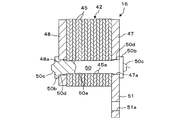
- the rotor core 42 and the end plates 47 and 48 are integrally fastened by caulking pins 50 as a plurality of fastening members on the circumference, as will be described later, so that the assembly of the rotor 16 is configured.
- One end plate 47 has an extending portion 51 extending radially inward, and a bolt insertion hole 51 a is formed in the extending portion 51.
- the end plate 47 is fixed to the side end surface of the output shaft 18 by bolts 52 (see FIG. 1) that pass through the bolt insertion holes 51a. Thereby, the rotor 16 (rotor core 42) of the electric motor 13 and the output shaft 18 are integrally rotated.
- a plurality of pin holes 45a through which caulking pins 50 are inserted are formed by punching or the like.
- the inner diameter of the pin hole 45a of the laminated steel plate 45 is formed to be substantially the same as the outer diameter of the caulking pin 50, and the caulking pin 50 is an intermediate fit between the pin hole 45a, that is, an intermediate fit between a clearance fit and an interference fit.
- the pin hole 45a of the laminated steel plate 45 (rotor core 42) and the caulking pin 50 are fitted with no gap.
- the pair of end plates 47, 48 have a plurality of circumferential insertion holes 47 a, 48 a having a diameter equal to or larger than the diameter of the pin hole 45 a formed in the rotor core 42 (laminated steel plate 45). It is formed in the same phase as 45a, and both ends of the caulking pin 50 are fitted in these insertion holes 47a and 48a without gaps by a diameter expanding process described later.
- the caulking pin 50 is caulked at both ends and is integrally fastened to the end plates 47 and 48, whereby the rotor core 42 sandwiched between the end plates 47 and 48 is integrated with the caulking pin 50 and the end plates 47 and 48. To be concluded.
- the caulking pin (fastening member) 50 is continuous with the main body portion 50a through which the rotor core 42 is inserted, and both end portions of the main body portion 50a, and through holes 47a, 48a of the end plates 47, 48.
- Main enlarged diameter portions 50b, 50b larger than the diameter of the main diameter enlarged portions 50b, 50b, and taper-shaped protrusions 50c, 50c that are continuous with the main enlarged diameter portions 50b, 50b and project from the main enlarged diameter portions 50b, 50b.
- the main body 50a has sub-expanded portions 50d and 50d having a diameter smaller than that of the main expanded portions 50b and 50b.
- the sub-expanded portions 50d and 50d are inserted into the insertion holes 47a and 48a of the end plates 47 and 48, respectively. It is arranged without gaps.
- the main enlarged diameter portions 50b and 50b are engaged with the end surfaces of the end plates 47 and 48, and the sub enlarged diameter portions 50d and 50d are fitted in close contact with the insertion holes 47a and 48a of the end plates 47 and 48.
- the caulking punches 80A and 80B can be easily removed from the protrusions 50c and 50c after being caulked by caulking punches 80A and 80B described later.
- the rotor core 42 is composed of a plurality of divided cores divided in the circumferential direction, and the laminated steel plates 45 constituting each divided core are fastened to the end plates 47, 48 by a plurality of caulking pins 50, respectively. ing. Prior to being fastened by the caulking pin 50, the plurality of laminated steel plates 45 are subjected to a known dowel caulking between the pin holes 45a in a state where the phases of the pin holes 45a are aligned, and temporarily positioned. It has come to be.
- FIG. 3 shows a method for manufacturing the rotor 16 of the electric motor 13 according to the first embodiment.
- the rotor core 42 tentatively positioned so that the phases of the pin holes 45a of the plurality of laminated steel plates 45 coincide with each other by the dowel caulking, and after the permanent magnet 46 is embedded, end plates 47 and 48 are formed on both sides thereof, and the insertion holes formed in them. 47a and 48a are superposed so as to coincide with the pin hole 45a of the rotor core 42 and positioned in the mold 55 in a horizontal state.
- the caulking pin 50 is inserted into the pin hole 45a of the rotor core 42 so that there is no gap between the caulking pin 50 and the pin hole 45a and that the laminated steel plate 45 is not deformed and fit. It can be done without difficulty by an intermediate fit. It should be noted that both ends of the caulking pin 50 inserted into the rotor core 42 are loosely fitted in the insertion holes 47a, 48a of the end plates 47, 48 with a slight gap between them. It is in a state of protruding quantitatively.
- the mold 55 in which the rotor core 42 is positioned is indexed in the “enlargement process” shown in FIG. 3B.
- the expansion punches 70A and 70B having both end surfaces of the caulking pins 50 with flat tip surfaces. Is pressed by.
- the diameters of both ends of the caulking pin 50 loosely fitted in the insertion holes 47a and 48a of the end plates 47 and 48 are expanded, and the sub-diameter enlarged portions 50d and 50d are formed.
- These sub enlarged diameter portions 50d and 50d are fitted into the insertion holes 47a and 48a of the end plates 47 and 48 without any gap.
- both end faces of the caulking pin 50 are flat at the front end face and are hollow caulking punches. It is pressed by 80A and 80B.
- the caulking punch 80A, 80B has a hollow hole 80A1 in which the diameter of the front end surface is sufficiently larger than the diameter of the sub enlarged diameter portions 50d, 50d of the expanded caulking pin 50 and sufficiently smaller than the diameter of the sub enlarged diameter portions 50d, 50d. , 80B1.
- the open ends of the hollow holes 80A1 and 80B1 are formed in a tapered shape whose diameter increases toward the end face.
- the both ends of the caulking pin 50 are caulked so as to protrude radially outward from the insertion holes 47a and 48a of the end plates 47 and 48, as shown in FIG. . That is, the diameters of both ends of the crimping pin 50 are enlarged to form main enlarged diameter portions 50b, 50b that engage with both end surfaces of the end plates 47, 48, and part of the meat at both ends of the crimping pin 50 is formed by crimping.
- the caulking punches 80A and 80B are released into the hollow holes 80A1 and 80B1, and tapered protrusions 50c protruding from the main enlarged diameter part are formed at both ends of the caulking pin 50.
- the rotor core 42 and the pair of end plates 47 and 48 are integrally fastened by the caulking pins 50, and the rotor 16 of the electric motor 13 is manufactured.
- the manufactured rotor 16 is supported inside the stator 15 of the electric motor 13 with a predetermined interval, and is fixed to the output shaft 18 by bolts 52.
- the hybrid vehicle drive device 10 configured as described above turns on the ignition switch (not shown) and the driver steps on the accelerator pedal (at the time of low throttle opening). A current flows from the motor (not shown) to the electric motor 13, and the electric motor 13 functions as a drive motor. Then, the rotational driving force is transmitted to the torque converter through the output shaft 18 and is increased by a predetermined torque ratio by the torque converter and then transmitted to the driving wheel through the transmission.
- the fuel injection device of the engine 11 does not operate and the engine 11 is in a stopped state. Then, the vehicle starts by only the driving force from the electric motor 13. At this time, the clutch device 14 is disengaged. Even in a region where the engine efficiency is poor, such as when the engine 11 is under a low load or under an extremely low load, the engine 11 is stopped, the vehicle runs only with the electric motor 13, and the clutch device 14 is disengaged.
- the engine 11 is started when accelerating or climbing.
- the accelerator pedal is stepped on to accelerate or climb up and the throttle is opened more than a certain degree of opening
- the fuel injection device is activated and the ignition plug is ignited and fixed to the housing 20 (see FIG. (Not shown) is driven, and the engine 11 is started.
- the clutch device 14 is engaged, the rotational driving force of the input shaft 17 is transmitted to the output shaft 18 via the clutch device 14.
- the driving forces of both the engine 11 and the electric motor 13 are added, and the vehicle travels with a large driving force.
- the electric motor 13 When the vehicle is in a steady high-speed traveling state, the electric motor 13 is operated without load (the motor output is controlled so as to cancel the torque generated by the counter electromotive force generated in the motor), and the electric motor 13 is idled. As a result, the vehicle travels solely by the driving force of the engine 11 while the clutch device 14 remains engaged.
- the rotor core 42 composed of the laminated steel plate 45 having the pin holes 45a and the insertion holes 47a and 48a having a diameter larger than the diameter of the pin holes 45a of the rotor core 42.
- a pair of end plates 47, 48 disposed on both sides of the rotor core 42, and the pin holes 45a of the rotor core 42 are inserted through intermediate fits, and the insertion holes 47a, 48a of the pair of end plates 47, 48 are inserted.
- Both ends are crimped, main body 50a, main enlarged portions 50b, 50b that are continuous with the main body 50a and are larger than the diameters of the insertion holes 47a, 48a of the end plates 47, 48,
- a fastening member (caulking) having protrusions 50c and 50c that are continuous with the main diameter-enlarged portions 50b and 50b and project from the main diameter-enlarged portions 50b and 50b. Down) it is equipped with a 50 and.
- the laminated steel plate 45 is not deformed by the insertion of the fastening member 50 into the pin hole 45a of the rotor core 42, and the fastening member 50 is fitted to the rotor core 42 and the pair of end plates 47, 48 without any gap. Therefore, it is possible to suppress displacement of the rotor core 42 and the end plates 47 and 48 due to the action of centrifugal force or the like caused by the rotation of the rotor 16.
- the “insertion step” is performed by performing the “insertion step”, the “expansion step”, and the “crimping step” separately. Therefore, the fastening member 50 can be inserted into the pin hole 45a of the rotor core 42 without difficulty so as not to deform the laminated steel plate 45 and without a gap.
- the gap between the fastening member 50 and the end plates 47 and 48 can be eliminated by forming the sub-diameter enlarged portions 50d and 50d by the “enlargement process”, and the “caulking process” can be performed with a small molding load.
- the rotor 16 can be manufactured with high accuracy while suppressing the deformation of the rotor 16 of the electric motor 13.
- the rotor core 42 side has been described as an example of sequentially indexing into the “insertion process”, “enlargement process”, and “caulking process”. It is also possible to manufacture the rotor 16 in a state where the punch 70 and the caulking punch 80 side are provided in an indexable manner and the rotor core 42 is fixed in the mold 55.
- FIG. 4 shows a method of manufacturing the rotor 16 of the electric motor 13 according to the second embodiment.
- the difference from the first embodiment is that the “insertion step” and the “enhancement step” are summarized as “ The rotor 16 of the electric motor 13 can be manufactured through two processes of “press-in process” and “press-in process” and “caulking process”.
- press-in process and “press-in process” and “caulking process”.
- the diameters of the insertion holes 47a and 48a formed in the pair of end plates 47 and 48 are made larger than the diameters of the pin holes 45a of the rotor core 42 as described in the first embodiment.
- the diameter difference is smaller than that in the case of the first embodiment.
- a plurality of caulking pins (fastening members) 50 on the circumference from the side of the insertion hole 48 a of the end plate 48 are pressed by the press-in punch 90.
- the caulking pin 50 is press-fitted into the insertion hole 48 a of the end plate 48 by interference fit, inserted into the pin hole 45 a of the rotor core 42 by intermediate fit, and into the insertion hole 47 a of the end plate 47. Press-fitted with a tight fit.
- both end surfaces of the caulking pin 50 are pressed by the flat and hollow caulking punches 80A and 80B.
- the By pressing with the caulking punches 80A and 80B, both end surfaces of the caulking pin 50 are caulked so as to protrude radially outward from the insertion holes 47a and 48a of the end plates 47 and 48, as shown in FIG.
- the diameter portions 50b and 50b are formed, and a tapered protrusion 50c protruding from the main enlarged diameter portion is formed.
- the “enlargement step” in the first embodiment is made possible by expanding the diameters of both ends of the crimping pin 50 by the “caulking step”. It is also possible to manufacture the rotor 16 of the electric motor 13 by two processes of “insertion process” and “caulking process”.
- the present invention is configured such that the rotor core 42 and the end plates 47 and 48 made of the laminated steel plate 45 are connected by caulking pins. It can be applied to the rotor 16 of a wide range of electric motors 13 that are fastened by 50.
- both end surfaces of the fastening member 50 are pressed by the hollow caulking punches 80A and 80B.
- the caulking punches 80A and 80B are caulked at both end portions of the fastening member 50 in a protruding shape. Any material that can be molded may be used.
- the rotor of an electric motor and a method for manufacturing the same according to the present invention are suitable for use in a structure in which a rotor core made of a laminated iron core is fastened by a fastening member.
Landscapes
- Engineering & Computer Science (AREA)
- Power Engineering (AREA)
- Manufacturing & Machinery (AREA)
- Iron Core Of Rotating Electric Machines (AREA)
- Manufacture Of Motors, Generators (AREA)
- Permanent Field Magnets Of Synchronous Machinery (AREA)
Abstract
Description
Claims (7)
- 永久磁石を収容した電動機の回転子であって、
ピン孔を有する積層鋼板からなるロータコアと、
該ロータコアのピン孔の径以上の径を有する挿通孔を有し、前記ロータコアの両側に配置される一対のエンドプレートと、
前記ロータコアのピン孔に挿通されるとともに、前記一対のエンドプレートの挿通孔に嵌合され、かつ両端部がカシメられ、本体部と、前記本体部に連続し、かつ前記エンドプレートの挿通孔の径よりも大きいメイン拡径部と、前記メイン拡径部に連続し、かつ前記メイン拡径部から突出する突部とを有する締結部材と、
を備えた電動機の回転子。 - 前記締結部材は、前記エンドプレートの挿通孔に密接するように嵌合する請求項1に記載の電動機の回転子。
- 前記突部はテーパ状をなす請求項1または2に記載の電動機の回転子。
- 前記本体部は前記メイン拡径部よりも径が小さいサブ拡径部を有し、前記サブ拡径部は前記エンドプレートの挿通孔内に配置される請求項1~3のいずれか一項に記載の電動機の回転子。
- 積層鋼板からなるロータコアの両側にエンドプレートを配置した電動機の回転子を製造する方法にして、
前記エンドプレートに形成した挿通孔を通して前記ロータコアに形成したピン孔に締結部材を挿入する工程と、
前記締結部材の両端部に前記エンドプレートの挿通孔の径よりも大きいメイン拡径部と、前記メイン拡径部に連続し、かつ前記メイン拡径部から突出する突部とが形成されるように、挿入された前記締結部材の両端面をカシメパンチによって押圧して成形する工程と、
を備えた電動機の回転子の製造方法。 - 前記ロータコアのピン孔に挿入された前記締結部材の両端面を押圧することにより前記締結部材の両端部の径を拡充して前記締結部材を前記エンドプレートの挿通孔に隙間なく嵌合する工程をさらに備えた請求項5に記載の電動機の回転子の製造方法。
- 前記突部はテーパ状をなす請求項5または6に記載の電動機の回転子の製造方法。
Priority Applications (2)
| Application Number | Priority Date | Filing Date | Title |
|---|---|---|---|
| US13/816,806 US20130140939A1 (en) | 2010-11-04 | 2011-10-12 | Rotor of electric motor and manufacturing method thereof |
| JP2012541795A JPWO2012060191A1 (ja) | 2010-11-04 | 2011-10-12 | 電動機の回転子およびその製造方法 |
Applications Claiming Priority (2)
| Application Number | Priority Date | Filing Date | Title |
|---|---|---|---|
| JP2010-247505 | 2010-11-04 | ||
| JP2010247505 | 2010-11-04 |
Publications (1)
| Publication Number | Publication Date |
|---|---|
| WO2012060191A1 true WO2012060191A1 (ja) | 2012-05-10 |
Family
ID=46024310
Family Applications (1)
| Application Number | Title | Priority Date | Filing Date |
|---|---|---|---|
| PCT/JP2011/073427 Ceased WO2012060191A1 (ja) | 2010-11-04 | 2011-10-12 | 電動機の回転子およびその製造方法 |
Country Status (3)
| Country | Link |
|---|---|
| US (1) | US20130140939A1 (ja) |
| JP (1) | JPWO2012060191A1 (ja) |
| WO (1) | WO2012060191A1 (ja) |
Cited By (2)
| Publication number | Priority date | Publication date | Assignee | Title |
|---|---|---|---|---|
| CN105186741A (zh) * | 2014-05-27 | 2015-12-23 | 比亚迪股份有限公司 | 电机转子和具有其的电机 |
| CN105322733A (zh) * | 2014-06-18 | 2016-02-10 | 株式会社三井高科技 | 层压铁芯的制造方法 |
Families Citing this family (9)
| Publication number | Priority date | Publication date | Assignee | Title |
|---|---|---|---|---|
| WO2017013773A1 (ja) * | 2015-07-22 | 2017-01-26 | Kyb株式会社 | バスバーユニット、これを備えた回転電機及びバスバーユニットの製造方法 |
| DE102016207634B4 (de) * | 2016-05-03 | 2025-11-06 | Valeo Eautomotive Germany Gmbh | Rotierende elektrische Maschine |
| JP6542835B2 (ja) * | 2017-05-30 | 2019-07-10 | ファナック株式会社 | 固定子及び回転電機 |
| DE102018126751A1 (de) * | 2018-10-26 | 2020-04-30 | Schaeffler Technologies AG & Co. KG | Elektromotor für einen Aktor eines Kraftfahrzeuges mit Befestigungskonzept für Rotor; sowie Kupplungsaktor |
| JP6830996B1 (ja) * | 2019-12-26 | 2021-02-17 | 山洋電気株式会社 | 同期電動機のフレーム構造並びにフレーム及び電機子の製造方法 |
| CN211981596U (zh) * | 2020-04-07 | 2020-11-20 | 精进电动科技股份有限公司 | 一种旋变定子定位压片和定位结构 |
| KR20220040265A (ko) * | 2020-09-23 | 2022-03-30 | 현대모비스 주식회사 | 모터 |
| JP7163948B2 (ja) * | 2020-10-30 | 2022-11-01 | 株式会社富士通ゼネラル | 圧縮機 |
| CN220210077U (zh) * | 2023-01-31 | 2023-12-19 | 日本电产株式会社 | 马达和电气产品 |
Citations (3)
| Publication number | Priority date | Publication date | Assignee | Title |
|---|---|---|---|---|
| JPH1014144A (ja) * | 1996-06-20 | 1998-01-16 | Matsushita Electric Ind Co Ltd | 小形電動機 |
| JP2007306688A (ja) * | 2006-05-10 | 2007-11-22 | Matsushita Electric Ind Co Ltd | モータ |
| JP2009081938A (ja) * | 2007-09-26 | 2009-04-16 | Aisin Seiki Co Ltd | モータ用ロータおよびモータ用ロータの製造方法 |
-
2011
- 2011-10-12 WO PCT/JP2011/073427 patent/WO2012060191A1/ja not_active Ceased
- 2011-10-12 US US13/816,806 patent/US20130140939A1/en not_active Abandoned
- 2011-10-12 JP JP2012541795A patent/JPWO2012060191A1/ja active Pending
Patent Citations (3)
| Publication number | Priority date | Publication date | Assignee | Title |
|---|---|---|---|---|
| JPH1014144A (ja) * | 1996-06-20 | 1998-01-16 | Matsushita Electric Ind Co Ltd | 小形電動機 |
| JP2007306688A (ja) * | 2006-05-10 | 2007-11-22 | Matsushita Electric Ind Co Ltd | モータ |
| JP2009081938A (ja) * | 2007-09-26 | 2009-04-16 | Aisin Seiki Co Ltd | モータ用ロータおよびモータ用ロータの製造方法 |
Cited By (2)
| Publication number | Priority date | Publication date | Assignee | Title |
|---|---|---|---|---|
| CN105186741A (zh) * | 2014-05-27 | 2015-12-23 | 比亚迪股份有限公司 | 电机转子和具有其的电机 |
| CN105322733A (zh) * | 2014-06-18 | 2016-02-10 | 株式会社三井高科技 | 层压铁芯的制造方法 |
Also Published As
| Publication number | Publication date |
|---|---|
| US20130140939A1 (en) | 2013-06-06 |
| JPWO2012060191A1 (ja) | 2014-05-12 |
Similar Documents
| Publication | Publication Date | Title |
|---|---|---|
| JPWO2012060191A1 (ja) | 電動機の回転子およびその製造方法 | |
| EP1415840B1 (en) | Drive device for hybrid vehicle | |
| KR100627030B1 (ko) | 하이브리드차용 구동장치 | |
| US7847444B2 (en) | Electric motor assembly with stator mounted in vehicle powertrain housing and method | |
| US20130127283A1 (en) | Rotor of an electric motor and manufacturing method of same | |
| JP2005168128A (ja) | 回転電機用ロータ | |
| JP2011254663A (ja) | 回転電機用ロータの製造方法及び回転電機用シャフト素材 | |
| JP2010178563A (ja) | アキシャルギャップ型モータ及びそのロータ製造方法 | |
| JP2015532231A (ja) | ハイブリッド車トランスミッションアセンブリのための組み立て済みモジュールおよびトランスミッションアセンブリを装着するための方法 | |
| CN101534037A (zh) | 用于电机的转子和用于汽车传动系的电机 | |
| JP2004242494A (ja) | ハイブリッド車両用電動機 | |
| US7737602B2 (en) | Rotating electrical machine or alternator and method of manufacturing rotor core used in the same | |
| JP5217333B2 (ja) | モータ用ロータおよびモータ用ロータの製造方法 | |
| JP2000289475A (ja) | ハイブリット車用駆動装置 | |
| KR20180050810A (ko) | 회전자 분할형 모터 | |
| JP5754324B2 (ja) | 回転電機のロータおよびロータの形成方法 | |
| JP2932883B2 (ja) | 電動機用ステータ鉄心および電動機用ステータ鉄心の製造方法 | |
| US6209191B1 (en) | Method for manufacturing pulley integrated type rotor | |
| JP2012023805A (ja) | 電動機の固定子とその製造方法 | |
| JP2012120262A (ja) | 電動機のステータコアの取付構造 | |
| KR101836526B1 (ko) | 환경 차량의 모터 회전자 어셈블리 | |
| WO2020255730A1 (ja) | 始動発電機及び始動発電機の製造方法 | |
| JP2001268853A (ja) | ブラシレスモータ | |
| JP2005192341A (ja) | ハイブリッド車用駆動装置 | |
| JPH10285852A (ja) | 磁石発電機の回転子 |
Legal Events
| Date | Code | Title | Description |
|---|---|---|---|
| 121 | Ep: the epo has been informed by wipo that ep was designated in this application |
Ref document number: 11837842 Country of ref document: EP Kind code of ref document: A1 |
|
| WWE | Wipo information: entry into national phase |
Ref document number: 2012541795 Country of ref document: JP |
|
| WWE | Wipo information: entry into national phase |
Ref document number: 13816806 Country of ref document: US |
|
| NENP | Non-entry into the national phase |
Ref country code: DE |
|
| 122 | Ep: pct application non-entry in european phase |
Ref document number: 11837842 Country of ref document: EP Kind code of ref document: A1 |