WO2012056534A1 - 内燃機関の燃料噴射制御システム - Google Patents
内燃機関の燃料噴射制御システム Download PDFInfo
- Publication number
- WO2012056534A1 WO2012056534A1 PCT/JP2010/069101 JP2010069101W WO2012056534A1 WO 2012056534 A1 WO2012056534 A1 WO 2012056534A1 JP 2010069101 W JP2010069101 W JP 2010069101W WO 2012056534 A1 WO2012056534 A1 WO 2012056534A1
- Authority
- WO
- WIPO (PCT)
- Prior art keywords
- pressure
- fuel
- internal combustion
- combustion engine
- fuel injection
- Prior art date
Links
Images


Classifications
-
- F—MECHANICAL ENGINEERING; LIGHTING; HEATING; WEAPONS; BLASTING
- F02—COMBUSTION ENGINES; HOT-GAS OR COMBUSTION-PRODUCT ENGINE PLANTS
- F02D—CONTROLLING COMBUSTION ENGINES
- F02D41/00—Electrical control of supply of combustible mixture or its constituents
- F02D41/30—Controlling fuel injection
- F02D41/3005—Details not otherwise provided for
-
- F—MECHANICAL ENGINEERING; LIGHTING; HEATING; WEAPONS; BLASTING
- F02—COMBUSTION ENGINES; HOT-GAS OR COMBUSTION-PRODUCT ENGINE PLANTS
- F02D—CONTROLLING COMBUSTION ENGINES
- F02D41/00—Electrical control of supply of combustible mixture or its constituents
- F02D41/30—Controlling fuel injection
- F02D41/38—Controlling fuel injection of the high pressure type
- F02D41/3809—Common rail control systems
- F02D41/3836—Controlling the fuel pressure
- F02D41/3845—Controlling the fuel pressure by controlling the flow into the common rail, e.g. the amount of fuel pumped
- F02D41/3854—Controlling the fuel pressure by controlling the flow into the common rail, e.g. the amount of fuel pumped with elements in the low pressure part, e.g. low pressure pump
-
- F—MECHANICAL ENGINEERING; LIGHTING; HEATING; WEAPONS; BLASTING
- F02—COMBUSTION ENGINES; HOT-GAS OR COMBUSTION-PRODUCT ENGINE PLANTS
- F02D—CONTROLLING COMBUSTION ENGINES
- F02D41/00—Electrical control of supply of combustible mixture or its constituents
- F02D41/02—Circuit arrangements for generating control signals
- F02D41/14—Introducing closed-loop corrections
- F02D41/1401—Introducing closed-loop corrections characterised by the control or regulation method
- F02D2041/1409—Introducing closed-loop corrections characterised by the control or regulation method using at least a proportional, integral or derivative controller
-
- F—MECHANICAL ENGINEERING; LIGHTING; HEATING; WEAPONS; BLASTING
- F02—COMBUSTION ENGINES; HOT-GAS OR COMBUSTION-PRODUCT ENGINE PLANTS
- F02D—CONTROLLING COMBUSTION ENGINES
- F02D2200/00—Input parameters for engine control
- F02D2200/02—Input parameters for engine control the parameters being related to the engine
- F02D2200/06—Fuel or fuel supply system parameters
- F02D2200/0602—Fuel pressure
-
- F—MECHANICAL ENGINEERING; LIGHTING; HEATING; WEAPONS; BLASTING
- F02—COMBUSTION ENGINES; HOT-GAS OR COMBUSTION-PRODUCT ENGINE PLANTS
- F02D—CONTROLLING COMBUSTION ENGINES
- F02D2250/00—Engine control related to specific problems or objectives
- F02D2250/02—Fuel evaporation in fuel rails, e.g. in common rails
-
- F—MECHANICAL ENGINEERING; LIGHTING; HEATING; WEAPONS; BLASTING
- F02—COMBUSTION ENGINES; HOT-GAS OR COMBUSTION-PRODUCT ENGINE PLANTS
- F02M—SUPPLYING COMBUSTION ENGINES IN GENERAL WITH COMBUSTIBLE MIXTURES OR CONSTITUENTS THEREOF
- F02M59/00—Pumps specially adapted for fuel-injection and not provided for in groups F02M39/00 -F02M57/00, e.g. rotary cylinder-block type of pumps
- F02M59/20—Varying fuel delivery in quantity or timing
- F02M59/36—Varying fuel delivery in quantity or timing by variably-timed valves controlling fuel passages to pumping elements or overflow passages
- F02M59/366—Valves being actuated electrically
Definitions
- the present invention relates to a fuel injection control system for an internal combustion engine provided with a low-pressure fuel pump (feed pump) and a high-pressure fuel pump (supply pump).
- a low-pressure fuel pump that sucks up fuel from the fuel tank, a high-pressure fuel pump that boosts the fuel sucked up by the low-pressure fuel pump to a pressure that can be injected into the cylinder
- a fuel injection control system comprising:
- Patent Document 1 describes a technique for determining that vapor is generated when the drive duty of a high-pressure fuel pump exceeds a predetermined value and increasing the feed pressure.
- Patent Document 2 a fluctuation rate of fuel pressure in a fuel pipe is obtained, and the generation of fuel vapor is estimated from the fluctuation rate.
- the target fuel pressure is increased and the vapor pressure is increased.
- a technique for lowering the target fuel pressure when non-occurrence of fuel is estimated is described.
- Patent Document 3 predicts whether or not fuel vapor is generated during the engine stop period based on the outside air temperature or the alcohol concentration in the fuel, and when the vapor generation is predicted, It describes the technology that keeps up.
- Patent Document 4 it is determined whether or not vapor is likely to be generated based on the concentration of evaporated fuel in the gas supplied to the internal combustion engine by the evaporated fuel processing device, and when it is determined that vapor is likely to be generated. A technique for increasing the discharge flow rate of the fuel pump is described.
- JP 2010-071224 A Japanese Patent Laying-Open No. 2005-076568 JP 2006-322401 A JP 2007-126986 A
- the present invention has been made in view of the above circumstances, and an object thereof is to induce misfire, turbulence of an air-fuel ratio, and the like in a fuel injection control system of an internal combustion engine including a low pressure fuel pump and a high pressure fuel pump. And providing a technique capable of making the feed pressure as low as possible.
- the present invention provides a fuel injection control system for an internal combustion engine that performs proportional integral control (PI control) on the drive duty of the high-pressure fuel pump based on the deviation between the discharge pressure of the high-pressure fuel pump and the target pressure.
- PI control proportional integral control
- I term integral term
- the present invention relates to a fuel injection control system for an internal combustion engine that boosts fuel discharged from a low-pressure fuel pump by a high-pressure fuel pump and supplies the fuel to a fuel injection valve.
- a processing unit for performing a lowering process for reducing a feed pressure that is a discharge pressure of the low-pressure fuel pump;
- a pressure sensor for detecting a discharge pressure of the high-pressure fuel pump;
- a control unit that performs proportional-integral control of a drive duty of the high-pressure fuel pump based on a deviation between a target discharge pressure of the high-pressure fuel pump and a detection value of the pressure sensor;
- a stop unit that stops the lowering process according to a change tendency of an integral term used for the proportional integral control during the lowering process; I was prepared to.
- the integral term also shows an increasing tendency when the fuel injection amount increases or when the fuel temperature rises.
- the factor that changes the integral term during the execution of the reduction process is the generation of vapor.
- the stop unit may stop the reduction process when the integral term of the proportional integration control shows an increasing tendency during the execution of the reduction process.
- the feed pressure can be reduced in a range where a large amount of vapor is not generated.
- the present invention does not require a pressure sensor, a temperature sensor, or the like in the fuel path between the low pressure fuel pump and the high pressure fuel pump, so the fuel injection control system can be simplified.
- the processing unit according to the present invention may maintain or increase the feed pressure when the lowering process is stopped by the stop unit. In this case, the amount of vapor generated is maintained within a range where no misfire or air-fuel ratio disturbance occurs, or the amount of vapor generated is reduced.
- the processing unit may increase the feed pressure when the change amount of the integral term is large compared to when it is small.
- the amount of change in the integral term becomes larger when the amount of vapor generated is larger than when the amount of vapor generated is small. For this reason, when the amount of change in the integral term is large, the amount of vapor generated can be more reliably reduced when the feed pressure is increased than when the amount of change is small.
- the feed pressure reduction rate may be changed in accordance with a parameter indicating the operating condition of the internal combustion engine.
- a parameter indicating the operating condition of the internal combustion engine The ease with which vapor is generated during the reduction process varies depending on the operating conditions of the internal combustion engine. For this reason, the feed pressure reduction rate may be reduced under operating conditions in which vapor is likely to be generated, compared to operating conditions in which vapor is less likely to be generated. In this case, the feed pressure can be reduced while avoiding a situation where the amount of vapor generated increases rapidly.
- a parameter correlated with the engine load or the fuel temperature can be used. Vapor is more likely to occur when the engine load is high than when it is low. For this reason, when the engine load is high, the rate of decrease in the feed pressure may be made lower than when the engine load is low. Also, vapor is more likely to occur when the fuel temperature is high than when the fuel temperature is low. For this reason, when the fuel temperature is high, the rate of decrease in the feed pressure may be made lower than when the fuel temperature is low.
- the temperature of intake air, the temperature of cooling water, the temperature of lubricating oil, or the absolute value of the integral term described above can be used as a parameter correlating with fuel temperature.
- the feed pressure can be made as low as possible without inducing misfire or turbulence of the air-fuel ratio.
- FIG. 1 is a diagram showing a schematic configuration of a fuel injection control system for an internal combustion engine.
- the fuel injection control system includes a fuel injection valve 1 for injecting fuel into a cylinder of an internal combustion engine.
- the fuel injection valve 1 is connected to a delivery pipe 2.
- four fuel injection valves 1 are connected to the delivery pipe, but the number of fuel injection valves 1 may be five or more, or may be three or less. .
- the fuel injection control system includes a low-pressure fuel pump 4 that pumps up fuel stored in the fuel tank 3.
- the low-pressure fuel pump 4 is a rotary pump (rotary pump) driven by an electric motor.
- the low-pressure fuel discharged from the low-pressure fuel pump 4 is sent to the suction port of the high-pressure fuel pump 6 through the low-pressure fuel passage 5.
- the high-pressure fuel pump 6 is a reciprocating pump (plunger pump) driven by the power of the internal combustion engine (for example, the rotational force of the camshaft).
- a suction valve 60 that switches between conduction and blockage of the suction port is provided at the suction port of the high-pressure fuel pump 6.
- the intake valve 60 is an electromagnetically driven valve mechanism, and changes the discharge amount of the high-pressure fuel pump 6 by changing the opening / closing timing with respect to the position of the plunger.
- the base end of the high-pressure fuel passage 7 is connected to the discharge port of the high-pressure fuel pump 6.
- the end of the high pressure fuel passage 7 is connected to the delivery pipe 2.
- the base end of the branch passage 8 is connected in the middle of the low-pressure fuel passage 5.
- the end of the branch passage 8 is connected to the fuel tank 3.
- a pressure regulator 9 is provided in the middle of the branch passage 8. The pressure regulator 9 is opened when the pressure (fuel pressure) in the low pressure fuel passage 5 exceeds a predetermined value, so that excess fuel in the low pressure fuel passage 5 is sent to the fuel tank 3 via the branch passage 8. return.
- a check valve 10 and a pulsation damper 11 are arranged in the middle of the high-pressure fuel passage 7.
- the check valve 10 is a one-way valve that allows a flow from the discharge port of the high-pressure fuel pump 6 to the delivery pipe 2 and restricts a flow from the delivery pipe 2 to the discharge port of the high-pressure fuel pump 6.
- the pulsation damper 11 attenuates fuel pulsation caused by the operation (suction operation and discharge operation) of the high-pressure fuel pump 6.
- the delivery pipe 2 is connected to a return passage 12 for returning surplus fuel in the delivery pipe 2 to the fuel tank 3.
- a relief valve 13 that switches between return and passage of the return passage 12 is disposed.
- the relief valve 13 is an electric or electromagnetically driven valve mechanism, and is opened when the fuel pressure in the delivery pipe 2 exceeds a target value.
- the end of the communication path 14 is connected.
- a base end of the communication path is connected to the high-pressure fuel pump 6.
- the communication passage 14 guides surplus fuel discharged from the high-pressure fuel pump 6 to the return passage 12.
- the fuel injection control system includes an electronic control unit (ECU) 15 that controls each device described above.
- the ECU 15 is electrically connected to various sensors such as a fuel pressure sensor 16, an intake air temperature sensor 17, an accelerator position sensor 18, and a crank position sensor 19.
- the fuel pressure sensor 16 is a sensor that outputs an electrical signal correlated with the fuel pressure in the delivery pipe 2.
- the fuel pressure sensor 16 may be disposed in the high pressure fuel passage 7.
- the intake air temperature sensor 17 outputs an electrical signal correlated with the temperature of air taken into the internal combustion engine.
- the accelerator position sensor 18 outputs an electrical signal correlated with the operation amount (accelerator opening) of the accelerator pedal.
- the crank position sensor 19 is a sensor that outputs an electrical signal correlated with the rotational position of the output shaft (crankshaft) of the internal combustion engine.
- the ECU 15 controls the low-pressure fuel pump 4 and the intake valve 60 based on the output signals of the various sensors described above. For example, the ECU 15 adjusts the opening / closing timing of the intake valve 60 so that the output signal (actual fuel pressure) of the fuel pressure sensor 16 converges to a target value. At that time, the ECU 15 performs proportional integral control (PI control) based on the deviation between the actual fuel pressure and the target value with respect to the drive duty (ratio of solenoid energization time and non-energization time) which is the control amount of the intake valve 60. Do.
- the target value described above is a value determined according to the target fuel injection amount of the fuel injection valve 1.
- the ECU 15 responds to the amount of control (feed-forward term) determined according to the target fuel injection amount and the difference between the actual fuel pressure and the target value (hereinafter referred to as “fuel pressure difference”).
- the drive duty is calculated by adding the control amount (proportional term) determined in this way and the control amount (integral term) obtained by integrating a part of the difference between the actual fuel pressure and the target value.
- the control part concerning this invention is implement
- the relationship between the fuel pressure difference and the feed-forward term and the relationship between the fuel pressure difference and the proportional term are determined in advance by an adaptation operation using experiments or the like.
- the ratio of the amount added to the integral term in the difference in the fuel pressure described above is determined in advance by an adaptation operation using an experiment or the like.
- the ECU 15 executes a reduction process for reducing the discharge pressure (feed pressure) of the low-pressure fuel pump 4 in order to reduce the power consumption of the low-pressure fuel pump 4 as much as possible. Specifically, the ECU 15 decreases the discharge pressure of the low-pressure fuel pump 4 by a certain amount (hereinafter referred to as “decrease coefficient”). Note that when the discharge pressure of the low-pressure fuel pump 4 rapidly decreases, the fuel pressure in the low-pressure fuel passage 5 may be significantly lower than the saturated vapor pressure of the fuel. In that case, a large amount of vapor is generated in the low-pressure fuel passage 5, and suction failure and discharge failure of the high-pressure fuel pump 6 are induced.
- the above-described reduction coefficient is set to the maximum value in a range where the fuel pressure in the low-pressure fuel passage 5 does not greatly fall below the saturated vapor pressure, and it is preferable to obtain the reduction coefficient in advance by an adaptation process such as an experiment. desirable.
- the low pressure fuel pump 4 when the fuel pressure in the low pressure fuel passage 5 is lower than the saturated vapor pressure of the fuel by the above-described reduction process, it is desirable to increase the discharge pressure of the low pressure fuel pump 4.
- a sensor for detecting the fuel pressure in the low pressure fuel passage 5 and a sensor for detecting the saturated vapor pressure of the fuel are provided, and when the fuel pressure in the low pressure fuel passage 5 falls below the saturation vapor pressure, the low pressure fuel pump 4 A method of increasing the discharge pressure is conceivable.
- the number of parts of the fuel injection control system increases, there is a problem that the on-vehicle performance is lowered and the manufacturing cost is increased.
- the discharge pressure of the low-pressure fuel pump 4 is adjusted based on the change tendency of the integral term used when calculating the drive duty of the high-pressure fuel pump 6.
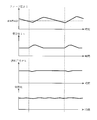
- FIG. 2 is a diagram showing the behavior of the integral term It and the fuel pressure Ph in the high-pressure fuel passage 7 when the discharge pressure (feed pressure) Pl of the low-pressure fuel pump 4 is continuously reduced.
- the integral term It shows a gentle increasing tendency.
- a suction failure or discharge failure of the high-pressure fuel pump 6 occurs (t2 in FIG. 2).
- the rate of increase of the integral term It increases and the fuel pressure Ph in the high-pressure fuel passage 7 decreases.
- a method of increasing the discharge pressure of the low-pressure fuel pump 4 when the magnitude (absolute value) of the integral term It exceeds a threshold value can be considered.
- the magnitude of the integral term It increases not only due to the generation of vapor but also due to an increase in the fuel temperature, an increase in the target injection amount, and the like.
- the discharge pressure of the low-pressure fuel pump 4 it is preferable to decrease the discharge pressure of the low-pressure fuel pump 4 when the integral term It is constant or tends to decrease, and to increase the discharge pressure of the low-pressure fuel pump 4 when the integral term It tends to increase.
- the occurrence of vapor can be detected before suction failure or discharge failure of the high-pressure fuel pump 6 occurs (for example, during the period from t1 to t2 in FIG. 2).
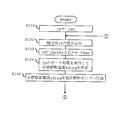
- FIG. 3 is a flowchart showing the lowering process routine.
- the lowering process routine is stored in advance in the ROM of the ECU 15, and is executed with the start of the internal combustion engine (for example, when the ignition switch is switched from OFF to ON) as a trigger.
- the ECU 15 first executes the process of S101. That is, the ECU 15 sets the drive current Id of the low pressure fuel pump 4 to the initial value Id0.
- the difference value ⁇ It shows a positive value (when the integral term It shows an increasing tendency)
- the drive current Id increases.
- the discharge pressure (feed pressure) Pl of the low-pressure fuel pump 4 increases.
- the stop portion according to the present invention is realized.
- the difference value ⁇ It is zero (when the integral term It is constant) or when the integral term It shows a negative value (when the integral term It tends to decrease)
- the drive current Id Decrease.
- the discharge pressure (feed pressure) Pl of the low-pressure fuel pump 4 decreases.
- the processing unit according to the present invention is realized.
- the ECU 15 executes a guard process for the drive current Id obtained in S103. That is, the ECU 15 determines whether or not the drive current Id obtained in S103 is a value not less than the lower limit value and not more than the upper limit value. When the drive current Id obtained in S103 is not less than the lower limit value and not more than the upper limit value, the ECU 15 determines the drive current Id as the target drive current Idtrg. When the drive current Id exceeds the upper limit value, the ECU 15 sets the target drive current Idtrg to a value equal to the upper limit value. When the drive current Id is below the lower limit value, the ECU 15 sets the target drive current Idtrg to a value equal to the lower limit value.
- the ECU 15 drives the low-pressure fuel pump 4 by applying the target drive current Idtrg determined in S104 to the low-pressure fuel pump 4.
- the ECU 15 repeatedly executes the processes after S102 after executing the process of S105.
- the ECU 15 executes the lowering process routine of FIG. 3, when the integral term It shows a constant or lowering tendency (when the difference value ⁇ It becomes a value equal to or less than zero), the discharge pressure of the low-pressure fuel pump 4 When the integral term It shows an increasing tendency (when the difference value ⁇ It shows a positive value), the discharge pressure of the low-pressure fuel pump 4 is increased.
- the present embodiment it is possible to stop the decrease in the feed pressure Pl before a large amount of vapor is generated in the low-pressure fuel passage 5 (when the vapor starts to be generated).
- the feed pressure Pl is increased as the difference value ⁇ It is increased. Therefore, it is possible to more reliably prevent the suction failure and the discharge failure of the high-pressure fuel pump 6. .
- the reduction process of this embodiment does not require a sensor for detecting the fuel pressure in the low-pressure fuel passage 5 or a sensor for detecting the saturated vapor pressure of the fuel. There will be no increase in
- the difference between the first embodiment described above and this embodiment is in the method of determining the reduction coefficient Cdwn. That is, in the first embodiment described above, the reduction coefficient Cdwn is set to a constant value, but in this embodiment, the reduction coefficient is changed according to the fuel temperature.
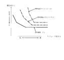
- FIG. 5 is a diagram showing the relationship between the feed pressure Pl and the magnitude (absolute value) of the integral term It.
- the solid line in FIG. 5 shows the relationship when the fuel temperature is T1.
- a one-dot chain line in FIG. 5 shows a relationship when the fuel temperature is T2 higher than T1.
- a two-dot chain line in FIG. 5 shows a relationship when the fuel temperature is T3 higher than T2.
- the lowering coefficient Cdwn is set to a smaller value when the fuel temperature is higher than when the fuel temperature is low.
- the rate of decrease of the feed pressure Pl during a certain period becomes slower when the fuel temperature is higher than when the fuel temperature is low.
- an actual value of the fuel temperature may be used as a parameter serving as an argument when determining the reduction coefficient Cdwn, but a temperature sensor needs to be attached to the low-pressure fuel passage 5.
- the temperature of the cooling water circulating through the internal combustion engine, the temperature of the lubricating oil of the internal combustion engine, or the output signal (intake air temperature) of the intake air temperature sensor 17 may be used.
- FIG. 7 is a diagram showing the correlation of the coolant temperature, the oil temperature, and the intake air temperature with respect to the fuel temperature.
- the solid line in FIG. 7 indicates the intake air temperature.
- the dashed-dotted line in FIG. 7 shows the temperature (oil temperature) of lubricating oil.
- a two-dot chain line in FIG. 7 indicates the temperature of the cooling water (cooling water temperature).
- the intake air temperature, the oil temperature, and the cooling water temperature show substantially the same changes as the fuel temperature.
- the intake air temperature has a higher correlation with the fuel temperature than the oil temperature and the coolant temperature.
- the intake air temperature shown in FIG. 7 is the temperature detected by the intake air temperature sensor 17 installed in the engine room. That is, it is considered that the temperature in the low pressure fuel passage 5 is substantially equal to the temperature in the engine room, and the temperature of the air detected by the intake air temperature sensor 17 is substantially equal to the temperature in the engine room. Therefore, in this embodiment, the output signal (intake air temperature) of the intake air temperature sensor 17 is used as a parameter correlated with the fuel temperature.
- the correlation between the various temperatures and the fuel temperature described above may vary depending on the specifications of the internal combustion engine and the specifications of the vehicle. In such a case, parameters other than the intake air temperature may be used.
- FIG. 8 is a flowchart showing a lowering process routine in the present embodiment.
- the same reference numerals are given to the processes equivalent to the above-described lowering process routine (see FIG. 3) of the first embodiment.
- the ECU 15 proceeds to S103 after executing the process of S203.
- the ECU 15 calculates the drive current Id of the low-pressure fuel pump 4 using the integral term It read in S102 and the decrease coefficient Cdwn obtained in S203.
- the feed pressure Pl can be reduced as quickly as possible without causing a significant decrease in the fuel pressure Ph or a disturbance in the air-fuel ratio. become.
- the intake air temperature, the cooling water temperature, and the oil temperature are exemplified as parameters correlated with the fuel temperature.
- the present invention is not limited to this.
- the magnitude (absolute value) of the integral term It tends to increase as the fuel temperature increases. Therefore, the reduction coefficient Cdwn may be determined using the magnitude (absolute value) of the integral term It as a parameter.
- the degree of increase of the integral term It in other words, the ease of occurrence of vapor in the low-pressure fuel passage 5, tends to increase when the load (accelerator opening) and the rotational speed of the internal combustion engine are high. Therefore, the reduction coefficient Cdwn may be determined using the load and rotation speed of the internal combustion engine as arguments, or the reduction coefficient Cdwn may be determined using the engine load and / or engine speed and fuel temperature as arguments.
Landscapes
- Engineering & Computer Science (AREA)
- Chemical & Material Sciences (AREA)
- Combustion & Propulsion (AREA)
- Mechanical Engineering (AREA)
- General Engineering & Computer Science (AREA)
- Electrical Control Of Air Or Fuel Supplied To Internal-Combustion Engine (AREA)
- Fuel-Injection Apparatus (AREA)
Abstract
Description
前記低圧燃料ポンプの吐出圧力であるフィード圧を低下させる低下処理を実行する処理部と、
前記高圧燃料ポンプの吐出圧力を検出する圧力センサと、
前記高圧燃料ポンプの目標吐出圧力と前記圧力センサの検出値との偏差に基づいて、前記高圧燃料ポンプの駆動デューティの比例積分制御を行う制御部と、
前記低下処理実行中の前記比例積分制御に用いられる積分項の変化傾向に応じて前記低下処理を停止させる停止部と、
を備えるようにした。
先ず、本発明の第1の実施例について図1乃至図4に基づいて説明する。図1は、内燃機関の燃料噴射制御システムの概略構成を示す図である。図1において、燃料噴射制御システムは、内燃機関の気筒内へ燃料を噴射するための燃料噴射弁1を備えている。燃料噴射弁1は、デリバリパイプ2に接続されている。なお、図1に示す例では、デリバリパイプに4つの燃料噴射弁1が接続されているが、燃料噴射弁1の個数は5つ以上であってもよく、あるいは3つ以下であってもよい。
Id=Idold+ΔIt*α-Cdwn
上記した式中のαは、なまし係数であり、予め実験などを用いた適合作業により求められている。
次に、本発明の第2の実施例について図5乃至図8に基づいて説明する。ここでは、前述した第1の実施例と異なる構成について説明し、同様の構成については説明を省略する。
2 デリバリパイプ
3 燃料タンク
4 低圧燃料ポンプ
5 低圧燃料通路
6 高圧燃料ポンプ
7 高圧燃料通路
8 分岐通路
9 プレッシャーレギュレータ
10 チェック弁
11 パルセーションダンパ
12 リターン通路
13 リリーフ弁
14 連通路
15 ECU
16 燃圧センサ
17 吸気温度センサ
18 アクセルポジションセンサ
19 クランクポジションセンサ
60 吸入弁
Claims (9)
- 低圧燃料ポンプから吐出される燃料を高圧燃料ポンプにより昇圧して燃料噴射弁へ供給する内燃機関の燃料噴射制御システムにおいて、
前記低圧燃料ポンプの吐出圧力であるフィード圧を低下させるための低下処理を実行する処理部と、
前記高圧燃料ポンプの吐出圧力を検出する圧力センサと、
前記高圧燃料ポンプの目標吐出圧力と前記圧力センサの検出値との偏差に基づいて、前記高圧燃料ポンプの駆動デューティの比例積分制御を行う制御部と、
前記低下処理実行中の比例積分制御に用いられる積分項の変化傾向に応じて前記低下処理を停止させる停止部と、
を備える内燃機関の燃料噴射制御システム。 - 請求項1において、前記停止部は、前記積分項が増加傾向を示すときに、前記低下処理を停止させる内燃機関の燃料噴射制御システム。
- 請求項1または2において、前記処理部は、前記停止部により前記低下処理が停止されたときに、前記フィード圧を維持または上昇させる内燃機関の燃料噴射制御システム。
- 請求項3において、前記処理部は、前記積分項の変化量が大きいときは小さいときに比べ、前記フィード圧を高める内燃機関の燃料噴射制御システム。
- 請求項1乃至4の何れか1項において、前記低下処理におけるフィード圧の低下速度は、内燃機関の運転条件に応じて変更される内燃機関の燃料噴射制御システム。
- 請求項5において、前記低下処理におけるフィード圧の低下速度は、燃料温度と相関する温度パラメータが低いときより高いときに遅くされる内燃機関の燃料噴射制御システム。
- 請求項6において、前記温度パラメータは、冷却水の温度と潤滑油の温度と吸気の温度との少なくとも1つである内燃機関の燃料噴射制御システム。
- 請求項5において、前記低下処理におけるフィードの低下速度は、機関負荷が低いときより高いときに遅くされる内燃機関の燃料噴射制御システム。
- 請求項1乃至4の何れか1項において、前記低下処理におけるフィード圧の低下速度は、前記積分項の絶対値が小さいときより大きいときに遅くされる内燃機関の燃料噴射制御システム。
Priority Applications (6)
| Application Number | Priority Date | Filing Date | Title |
|---|---|---|---|
| BR112012033464A BR112012033464A2 (pt) | 2010-10-27 | 2010-10-27 | sistema de controle de injeção de combustível para motor de combustão interna |
| PCT/JP2010/069101 WO2012056534A1 (ja) | 2010-10-27 | 2010-10-27 | 内燃機関の燃料噴射制御システム |
| CN201080068600.1A CN103080528B (zh) | 2010-10-27 | 2010-10-27 | 内燃机的燃料喷射控制系统 |
| EP10858923.5A EP2634411B1 (en) | 2010-10-27 | 2010-10-27 | Fuel injection control system for an internal combustion engine |
| US13/814,759 US9074550B2 (en) | 2010-10-27 | 2010-10-27 | Fuel injection control system for internal combustion engine |
| JP2012540574A JP5494818B2 (ja) | 2010-10-27 | 2010-10-27 | 内燃機関の燃料噴射制御システム |
Applications Claiming Priority (1)
| Application Number | Priority Date | Filing Date | Title |
|---|---|---|---|
| PCT/JP2010/069101 WO2012056534A1 (ja) | 2010-10-27 | 2010-10-27 | 内燃機関の燃料噴射制御システム |
Publications (1)
| Publication Number | Publication Date |
|---|---|
| WO2012056534A1 true WO2012056534A1 (ja) | 2012-05-03 |
Family
ID=45993289
Family Applications (1)
| Application Number | Title | Priority Date | Filing Date |
|---|---|---|---|
| PCT/JP2010/069101 WO2012056534A1 (ja) | 2010-10-27 | 2010-10-27 | 内燃機関の燃料噴射制御システム |
Country Status (6)
| Country | Link |
|---|---|
| US (1) | US9074550B2 (ja) |
| EP (1) | EP2634411B1 (ja) |
| JP (1) | JP5494818B2 (ja) |
| CN (1) | CN103080528B (ja) |
| BR (1) | BR112012033464A2 (ja) |
| WO (1) | WO2012056534A1 (ja) |
Cited By (3)
| Publication number | Priority date | Publication date | Assignee | Title |
|---|---|---|---|---|
| US20140230791A1 (en) * | 2011-09-28 | 2014-08-21 | Toyota Jidosha Kabushiki Kaisha | Fuel injection control system for an internal combustion engine |
| US9188077B2 (en) | 2011-07-01 | 2015-11-17 | Toyota Jidosha Kabushiki Kaisha | Fuel injection control system for internal combustion engine |
| JP2016223299A (ja) * | 2015-05-27 | 2016-12-28 | トヨタ自動車株式会社 | 車両の制御装置 |
Families Citing this family (7)
| Publication number | Priority date | Publication date | Assignee | Title |
|---|---|---|---|---|
| CN102434302B (zh) * | 2011-12-31 | 2016-01-06 | 中国第一汽车股份有限公司 | 缸内直喷汽油机高压起动控制方法 |
| JP5875970B2 (ja) * | 2012-12-21 | 2016-03-02 | 愛三工業株式会社 | 自動車の燃料供給装置 |
| GB201316439D0 (en) * | 2013-09-16 | 2013-10-30 | Delphi Tech Holding Sarl | Hybrid fuel injection equipment |
| US10738749B1 (en) * | 2019-01-18 | 2020-08-11 | Pratt & Whitney Canada Corp. | Method of using heat from fuel of common-rail injectors |
| US10865728B2 (en) | 2019-01-18 | 2020-12-15 | Pratt & Whitney Canada Corp. | Method of using backflow from common-rail fuel injector |
| JP6852754B2 (ja) * | 2019-06-17 | 2021-03-31 | トヨタ自動車株式会社 | 燃料噴射制御装置 |
| CN115628146B (zh) * | 2022-09-30 | 2024-08-20 | 东风汽车集团股份有限公司 | 直喷发动机油压控制方法、装置、设备及存储介质 |
Citations (4)
| Publication number | Priority date | Publication date | Assignee | Title |
|---|---|---|---|---|
| JP2005307931A (ja) * | 2004-04-26 | 2005-11-04 | Hitachi Ltd | 内燃機関の燃料供給装置 |
| JP2008175080A (ja) * | 2007-01-16 | 2008-07-31 | Hitachi Ltd | 内燃機関の燃料供給装置 |
| JP2010071224A (ja) * | 2008-09-19 | 2010-04-02 | Toyota Motor Corp | 内燃機関の燃料供給装置 |
| JP2010185308A (ja) * | 2009-02-10 | 2010-08-26 | Toyota Motor Corp | 内燃機関の燃料供給装置 |
Family Cites Families (10)
| Publication number | Priority date | Publication date | Assignee | Title |
|---|---|---|---|---|
| DE10001882A1 (de) * | 2000-01-19 | 2001-08-02 | Bosch Gmbh Robert | Verfahren zum Betrieb einer Vorförderpumpe eines Kraftstoffzumesssystems und Kraftstoffzumesssystem einer direkteinspritzenden Brennkraftmaschine |
| JP2005076568A (ja) | 2003-09-02 | 2005-03-24 | Nissan Motor Co Ltd | 内燃機関の燃料供給装置 |
| DE102004045738B4 (de) * | 2004-09-21 | 2013-05-29 | Continental Automotive Gmbh | Verfahren und Vorrichtung zum Steuern einer Brennkraftmaschine |
| CN101451475A (zh) * | 2004-10-07 | 2009-06-10 | 丰田自动车株式会社 | 用于内燃机的燃料供应设备 |
| JP2006258032A (ja) * | 2005-03-18 | 2006-09-28 | Toyota Motor Corp | 車両の制御装置 |
| JP4534866B2 (ja) | 2005-05-19 | 2010-09-01 | トヨタ自動車株式会社 | エンジンの制御装置 |
| EP1757793A1 (en) * | 2005-08-22 | 2007-02-28 | Inergy Automotive Systems Research (SA) | Fuel pump control system |
| JP4242380B2 (ja) | 2005-11-01 | 2009-03-25 | 本田技研工業株式会社 | 燃料ポンプの制御装置 |
| IT1395038B1 (it) * | 2009-08-12 | 2012-09-05 | Magneti Marelli Spa | Metodo di controllo di un impianto di iniezione diretta di tipo common-rail |
| US8820299B2 (en) * | 2011-04-27 | 2014-09-02 | Toyota Jidosha Kabushiki Kaisha | Fuel injection control system for internal combustion engine |
-
2010
- 2010-10-27 BR BR112012033464A patent/BR112012033464A2/pt not_active Application Discontinuation
- 2010-10-27 CN CN201080068600.1A patent/CN103080528B/zh not_active Expired - Fee Related
- 2010-10-27 US US13/814,759 patent/US9074550B2/en not_active Expired - Fee Related
- 2010-10-27 WO PCT/JP2010/069101 patent/WO2012056534A1/ja active Application Filing
- 2010-10-27 JP JP2012540574A patent/JP5494818B2/ja not_active Expired - Fee Related
- 2010-10-27 EP EP10858923.5A patent/EP2634411B1/en active Active
Patent Citations (4)
| Publication number | Priority date | Publication date | Assignee | Title |
|---|---|---|---|---|
| JP2005307931A (ja) * | 2004-04-26 | 2005-11-04 | Hitachi Ltd | 内燃機関の燃料供給装置 |
| JP2008175080A (ja) * | 2007-01-16 | 2008-07-31 | Hitachi Ltd | 内燃機関の燃料供給装置 |
| JP2010071224A (ja) * | 2008-09-19 | 2010-04-02 | Toyota Motor Corp | 内燃機関の燃料供給装置 |
| JP2010185308A (ja) * | 2009-02-10 | 2010-08-26 | Toyota Motor Corp | 内燃機関の燃料供給装置 |
Cited By (3)
| Publication number | Priority date | Publication date | Assignee | Title |
|---|---|---|---|---|
| US9188077B2 (en) | 2011-07-01 | 2015-11-17 | Toyota Jidosha Kabushiki Kaisha | Fuel injection control system for internal combustion engine |
| US20140230791A1 (en) * | 2011-09-28 | 2014-08-21 | Toyota Jidosha Kabushiki Kaisha | Fuel injection control system for an internal combustion engine |
| JP2016223299A (ja) * | 2015-05-27 | 2016-12-28 | トヨタ自動車株式会社 | 車両の制御装置 |
Also Published As
| Publication number | Publication date |
|---|---|
| US9074550B2 (en) | 2015-07-07 |
| BR112012033464A2 (pt) | 2016-11-22 |
| EP2634411B1 (en) | 2019-12-04 |
| US20130138327A1 (en) | 2013-05-30 |
| EP2634411A1 (en) | 2013-09-04 |
| CN103080528B (zh) | 2015-01-14 |
| CN103080528A (zh) | 2013-05-01 |
| EP2634411A4 (en) | 2016-08-10 |
| JPWO2012056534A1 (ja) | 2014-03-20 |
| JP5494818B2 (ja) | 2014-05-21 |
Similar Documents
| Publication | Publication Date | Title |
|---|---|---|
| JP5494818B2 (ja) | 内燃機関の燃料噴射制御システム | |
| JP5387538B2 (ja) | 筒内噴射式内燃機関のフェールセーフ制御装置 | |
| WO2013046359A1 (ja) | 内燃機関の燃料噴射制御システム | |
| JP5288049B2 (ja) | 内燃機関の燃料噴射制御システム | |
| US20140251280A1 (en) | Control apparatus for internal combustion engine and control method for internal combustion engine | |
| JP2010106732A (ja) | 筒内噴射式の内燃機関の制御装置 | |
| JP6146274B2 (ja) | 内燃機関の制御装置 | |
| JP5733396B2 (ja) | 内燃機関の燃料噴射制御システム | |
| JP2013231362A (ja) | 燃料圧力制御装置 | |
| WO2014119289A1 (ja) | 高圧ポンプの制御装置 | |
| JP2010071132A (ja) | エンジンの燃料供給装置 | |
| JP5708396B2 (ja) | 内燃機関の燃料噴射制御システム | |
| JP2009221906A (ja) | 筒内噴射式内燃機関の低圧ポンプ制御装置 | |
| JP5835117B2 (ja) | 内燃機関の燃料供給制御装置 | |
| JP5708411B2 (ja) | 内燃機関の燃料噴射制御システム | |
| JP5716684B2 (ja) | 内燃機関の燃料噴射制御システム | |
| JP5549398B2 (ja) | セタン価推定装置 | |
| JP4281825B2 (ja) | 高圧燃料噴射系の燃料圧制御装置 | |
| JP2001295725A (ja) | 内燃機関の燃料圧力制御装置 | |
| JP2014206141A (ja) | 内燃機関の燃料供給装置 | |
| JPWO2013046359A1 (ja) | 内燃機関の燃料噴射制御システム | |
| WO2013153663A1 (ja) | 内燃機関の燃料噴射制御システム | |
| JP2013108358A (ja) | 内燃機関の燃料噴射制御システム | |
| JP6201711B2 (ja) | 内燃機関の燃料供給装置 | |
| JP2009299542A (ja) | 内燃機関の燃料供給装置 |
Legal Events
| Date | Code | Title | Description |
|---|---|---|---|
| WWE | Wipo information: entry into national phase |
Ref document number: 201080068600.1 Country of ref document: CN |
|
| 121 | Ep: the epo has been informed by wipo that ep was designated in this application |
Ref document number: 10858923 Country of ref document: EP Kind code of ref document: A1 |
|
| ENP | Entry into the national phase |
Ref document number: 2012540574 Country of ref document: JP Kind code of ref document: A |
|
| WWE | Wipo information: entry into national phase |
Ref document number: 13814759 Country of ref document: US |
|
| WWE | Wipo information: entry into national phase |
Ref document number: 2010858923 Country of ref document: EP |
|
| NENP | Non-entry into the national phase |
Ref country code: DE |
|
| REG | Reference to national code |
Ref country code: BR Ref legal event code: B01A Ref document number: 112012033464 Country of ref document: BR |
|
| ENP | Entry into the national phase |
Ref document number: 112012033464 Country of ref document: BR Kind code of ref document: A2 Effective date: 20121227 |