WO2012053588A1 - ベーンポンプ - Google Patents
ベーンポンプ Download PDFInfo
- Publication number
- WO2012053588A1 WO2012053588A1 PCT/JP2011/074149 JP2011074149W WO2012053588A1 WO 2012053588 A1 WO2012053588 A1 WO 2012053588A1 JP 2011074149 W JP2011074149 W JP 2011074149W WO 2012053588 A1 WO2012053588 A1 WO 2012053588A1
- Authority
- WO
- WIPO (PCT)
- Prior art keywords
- back pressure
- rotor
- groove
- vane
- pump
- Prior art date
- Legal status (The legal status is an assumption and is not a legal conclusion. Google has not performed a legal analysis and makes no representation as to the accuracy of the status listed.)
- Ceased
Links
Images



Classifications
-
- F—MECHANICAL ENGINEERING; LIGHTING; HEATING; WEAPONS; BLASTING
- F04—POSITIVE - DISPLACEMENT MACHINES FOR LIQUIDS; PUMPS FOR LIQUIDS OR ELASTIC FLUIDS
- F04C—ROTARY-PISTON, OR OSCILLATING-PISTON, POSITIVE-DISPLACEMENT MACHINES FOR LIQUIDS; ROTARY-PISTON, OR OSCILLATING-PISTON, POSITIVE-DISPLACEMENT PUMPS
- F04C2/00—Rotary-piston machines or pumps
-
- F—MECHANICAL ENGINEERING; LIGHTING; HEATING; WEAPONS; BLASTING
- F01—MACHINES OR ENGINES IN GENERAL; ENGINE PLANTS IN GENERAL; STEAM ENGINES
- F01C—ROTARY-PISTON OR OSCILLATING-PISTON MACHINES OR ENGINES
- F01C21/00—Component parts, details or accessories not provided for in groups F01C1/00 - F01C20/00
- F01C21/08—Rotary pistons
- F01C21/0809—Construction of vanes or vane holders
- F01C21/0818—Vane tracking; control therefor
- F01C21/0854—Vane tracking; control therefor by fluid means
- F01C21/0863—Vane tracking; control therefor by fluid means the fluid being the working fluid
-
- F—MECHANICAL ENGINEERING; LIGHTING; HEATING; WEAPONS; BLASTING
- F04—POSITIVE - DISPLACEMENT MACHINES FOR LIQUIDS; PUMPS FOR LIQUIDS OR ELASTIC FLUIDS
- F04C—ROTARY-PISTON, OR OSCILLATING-PISTON, POSITIVE-DISPLACEMENT MACHINES FOR LIQUIDS; ROTARY-PISTON, OR OSCILLATING-PISTON, POSITIVE-DISPLACEMENT PUMPS
- F04C2/00—Rotary-piston machines or pumps
- F04C2/30—Rotary-piston machines or pumps having the characteristics covered by two or more groups F04C2/02, F04C2/08, F04C2/22, F04C2/24 or having the characteristics covered by one of these groups together with some other type of movement between co-operating members
- F04C2/34—Rotary-piston machines or pumps having the characteristics covered by two or more groups F04C2/02, F04C2/08, F04C2/22, F04C2/24 or having the characteristics covered by one of these groups together with some other type of movement between co-operating members having the movement defined in groups F04C2/08 or F04C2/22 and relative reciprocation between the co-operating members
- F04C2/344—Rotary-piston machines or pumps having the characteristics covered by two or more groups F04C2/02, F04C2/08, F04C2/22, F04C2/24 or having the characteristics covered by one of these groups together with some other type of movement between co-operating members having the movement defined in groups F04C2/08 or F04C2/22 and relative reciprocation between the co-operating members with vanes reciprocating with respect to the inner member
- F04C2/3446—Rotary-piston machines or pumps having the characteristics covered by two or more groups F04C2/02, F04C2/08, F04C2/22, F04C2/24 or having the characteristics covered by one of these groups together with some other type of movement between co-operating members having the movement defined in groups F04C2/08 or F04C2/22 and relative reciprocation between the co-operating members with vanes reciprocating with respect to the inner member the inner and outer member being in contact along more than one line or surface
Definitions
- the present invention relates to a vane pump used as a fluid pressure supply source.
- a vane pump is one in which a plurality of vanes are stored in radial slits formed in a rotor. Each vane is urged in a direction protruding from the slit by the pressure of the back pressure chamber that presses the base end portion and the centrifugal force that acts as the rotor rotates, and the tip portion of the vane is the cam surface on the inner periphery of the cam ring. Slid in contact. As a result, the vane slidably contacting the cam surface is reciprocated as the rotor rotates, the pump chamber expands and contracts, and hydraulic oil is supplied to and discharged from the pump chamber.
- JP11-230057A proposes a vane pump in which a back pressure groove communicating with the back pressure chamber and a communication groove communicating between the back pressure grooves are formed on the front and rear pressure plates provided so as to sandwich the rotor and each vane. is doing.
- the communication grooves are formed in different shapes between the front and rear pressure plates. According to this vane pump, the sealing performance of the pump chamber can be enhanced.
- An object of the present invention is to allow the pump discharge pressure of the vane pump to rise quickly.
- a vane pump includes a cam ring having a cam surface formed on an inner periphery thereof, a rotor provided on an inner periphery of the cam ring and driven to rotate with respect to the cam ring, A plurality of slits radially formed on the outer periphery, a plurality of vanes that are slidably inserted into the slits and whose tip portions are slidably contacted with the cam surface, and the cam surface and the rotor by the vane A plurality of pump chambers defined therebetween, a plurality of back pressure chambers defined between the base end portion of the vane and the slit and capable of pressing the vane toward the cam surface, and the rotor Are provided with a plurality of back pressure grooves that can communicate with the back pressure chamber, and a plurality of communication grooves that communicate the back pressure grooves adjacent to each other in the circumferential direction of the rotor.
- the communication groove that is formed above the rotation center of the rotor and communicates with the back pressure groove located in the suction area that sucks the working fluid into the pump chamber is located in another suction area that is formed below the rotation center of the rotor.
- the passage cross-sectional area is formed larger than that of the communication groove communicating with the other back pressure groove.
- FIG. 1 is a front view showing a state in which a pump cover of a vane pump according to an embodiment of the present invention is removed.
- FIG. 2 is a front view of the side plate of the vane pump according to the embodiment of the present invention.
- FIG. 3 is a front view of a pump cover of the vane pump according to the embodiment of the present invention.
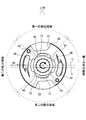
- FIG. 4 is a front view showing a state in the cam ring when the vane pump is stopped according to the embodiment of the present invention.
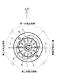
- FIG. 5 is a front view showing a state in the cam ring when the vane pump according to the embodiment of the present invention is mounted in a different posture.
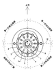
- FIG. 6 is a front view showing a state in the cam ring when the vane pump according to the embodiment of the present invention is mounted in a different posture.
- the vane pump 1 is used for hydraulic equipment mounted on a vehicle.
- the vane pump 1 is used as a hydraulic pressure supply source such as a power steering device or a transmission.
- the vane pump 1 uses hydraulic oil as a working fluid.
- a hydraulic fluid such as a water-soluble alternative liquid may be used as the hydraulic fluid instead of the hydraulic oil.
- the vane pump 1 includes a pump body 10 having a pump housing recess 10a in which the rotor 2, cam ring 4, side plate 30 and the like are housed, and a pump cover 50 that is fastened to the pump body 10 and seals the pump housing recess 10a.
- the vane pump 1 is configured such that power is transmitted from an engine (not shown) to the end of the drive shaft 9, and the rotor 2 connected to the drive shaft 9 is rotationally driven.
- the rotor 2 rotates in the direction indicated by the arrow in FIGS.
- the drive shaft 9 is rotatably supported by the pump body 10 and the pump cover 50.
- a high-pressure chamber (not shown) is defined between the bottom of the pump housing recess 10 a of the pump body 10 and the side plate 30.
- the side plate 30 is pressed against the rear end face of the cam ring 4 by the pump discharge pressure guided to the high pressure chamber.
- the vane pump 1 includes a plurality of vanes 3 provided so as to be capable of reciprocating in the radial direction with respect to the rotor 2, and a cam ring in which the rotor 2 and the vanes 3 are accommodated and the tip of the vane 3 slides as the rotor 2 rotates. 4.
- the rotor 2 is provided on the inner periphery of the cam ring 4.
- a plurality of slits 5 having openings on the outer peripheral surface are radially formed at predetermined intervals.
- the vane 3 is formed in a rectangular plate shape. The vane 3 is slidably inserted into the slit 5 and its tip can be slidably contacted with the cam surface 4a.
- a plurality of pump chambers 7 are defined by the outer peripheral surface of the rotor 2, the cam surface 4 a of the cam ring, and the adjacent vanes 3.
- the cam ring 4 is an annular member having a cam surface 4a formed in a substantially oval shape on the inner periphery thereof.
- the cam surface 4a is formed such that each vane 3 following the cam surface 4a reciprocates twice as the rotor 2 makes one rotation.
- the vane pump 1 has a first region where the vane 3 reciprocates for the first time and a second region where the vane 3 reciprocates for the second time.
- the first region is a first suction in which the volume of the pump chamber 7 defined by each vane 3 sliding on the cam surface 4 a is expanded as the rotor 2 rotates, and the working oil is sucked into the pump chamber 7. And a first discharge region in which the volume of the pump chamber 7 contracts and the hydraulic oil in the pump chamber 7 is discharged.
- the volume of the pump chamber 7 defined by the vanes 3 that slide on the cam surface 4 a expands and the hydraulic oil is sucked into the pump chamber 7.
- the second suction region and the second discharge region where the volume of the pump chamber 7 contracts and the hydraulic oil in the pump chamber 7 is discharged.
- the vane pump 1 has two suction areas and two discharge areas. Not only this but it is good also as a structure which has three or more suction area
- a first suction port 51 is opened in the first suction area
- a first discharge port 52 is opened in the first discharge area
- a second suction port 53 opens in the suction area
- a second discharge port 54 opens in the second discharge area.
- the first suction port 51 and the second suction port 53 communicate with a tank (not shown) through the suction passage 25.
- the hydraulic oil from the tank is guided to the first suction port 51 and the second suction port 53.
- a first suction port 31 is opened in the first suction area on the rear end surface of the side plate 30 where the rotor 2 is in sliding contact, and the first discharge port is formed in the first discharge area.
- 32 opens, the second suction port 33 opens in the second suction area, and the second discharge port 34 opens in the second discharge area.
- the first discharge port 32 and the second discharge port 34 communicate with hydraulic equipment through a pump discharge passage (not shown). Thereby, the pressurized hydraulic fluid discharged from the first discharge port 32 and the second discharge port 34 is supplied to the hydraulic equipment.
- a back pressure chamber 6 is defined on the back side of each slit 5 between the base end portion of the vane 3 and capable of biasing the vane 3 toward the cam surface 4a.
- the vane 3 is urged in a direction protruding from the slit 5 by the pressure of the back pressure chamber 6 that presses the base end portion thereof and the centrifugal force that acts as the rotor 2 rotates. As a result, the tip of the vane 3 comes into sliding contact with the cam surface 4 a of the cam ring 4.
- a first suction side back pressure groove 35, a first discharge side back pressure groove 36, and a second suction side back pressure groove are formed on the end surface of the side plate 30 where the rotor 2 is in sliding contact.
- 37 and the second discharge-side back pressure groove 38 are formed side by side in an arc shape.
- the first suction side back pressure groove 35, the first discharge side back pressure groove 36, the second suction side back pressure groove 37, and the second discharge side back pressure groove 38 are used to rotate the rotor 2. Accordingly, communication with the back pressure chamber 6 is possible.
- a first communication groove 41 that communicates the first suction-side back pressure groove 35 and the first discharge-side back pressure groove 36 to the end surface of the side plate 30 that is in sliding contact with the rotor 2, and the first discharge
- the second communication groove 42 communicating the side back pressure groove 36 and the second suction side back pressure groove 37, and the second suction side back pressure groove 37 and the second discharge side back pressure groove 38 are communicated.
- a third communication groove 43, a fourth communication groove 44 that communicates the second discharge-side back pressure groove 38 and the first suction-side back pressure groove 35 are formed side by side in an arc shape.
- the first suction side back pressure groove 35 opens to the first suction region.
- the first discharge side back pressure groove 36 opens in the first discharge region.
- the second suction side back pressure groove 37 opens to the second suction region.
- the second discharge side back pressure groove 38 opens in the second discharge region.
- the first suction side back pressure groove 35 communicates with the high pressure chamber through the high pressure chamber communication hole 15.
- the second suction side back pressure groove 37 communicates with the high pressure chamber via the high pressure chamber communication hole 17. Accordingly, the pump discharge pressure from the high pressure chamber is guided to the first suction side back pressure groove 35 and the second suction side back pressure groove 37.
- the pump discharge pressure is guided to each back pressure chamber 6 facing the first suction side back pressure groove 35 and the second suction side back pressure groove 37. Therefore, the base end portion of each vane 3 located in the first suction region and the second suction region is pressed by the pump discharge pressure guided to each back pressure chamber 6.
- the pump discharge pressure is supplied to the first discharge-side back pressure groove 36 via the first communication groove 41, the second communication groove 42, the third communication groove 43, and the fourth communication groove 44. It is guided to the second discharge side back pressure groove 38.
- the pump discharge pressure is guided to each back pressure chamber 6 facing the first discharge side back pressure groove 36 and the second discharge side back pressure groove 38. Therefore, the base end portion of each vane 3 located in the first discharge region and the second discharge region is also pressed by the pump discharge pressure guided to each back pressure chamber 6.
- the passage lengths of the first communication groove 41, the second communication groove 42, the third communication groove 43, and the fourth communication groove 44 are formed substantially equal to each other.
- the first suction side back pressure groove 55, the first discharge side back pressure groove 56, and the second suction side back pressure groove are formed on the end surface of the pump cover 50 where the rotor 2 is in sliding contact.
- 57 and the second discharge-side back pressure groove 58 are formed side by side in an arc shape.
- the first suction-side back pressure groove 55, the first discharge-side back pressure groove 56, the second suction-side back pressure groove 57, and the second discharge-side back pressure groove 58 are used to rotate the rotor 2. Accordingly, communication with the back pressure chamber 6 is possible.
- a first communication groove 61 that communicates the first suction-side back pressure groove 55 and the first discharge-side back pressure groove 56 with the end surface of the pump cover 50 where the rotor 2 is in sliding contact, and the first discharge
- the second communication groove 62 that allows the side back pressure groove 56 and the second suction side back pressure groove 57 to communicate with each other, and the second suction side back pressure groove 57 and the second discharge side back pressure groove 58 that communicate with each other.
- a third communication groove 63, a fourth communication groove 64 that communicates the second discharge side back pressure groove 58 and the first suction side back pressure groove 55 are formed side by side in an arc shape.
- the first suction side back pressure groove 55 opens to the first suction region.
- the first discharge-side back pressure groove 56 opens in the first discharge region.
- the second suction side back pressure groove 57 opens to the second suction region.
- the second discharge-side back pressure groove 58 opens in the second discharge region.
- the passage lengths of the first communication groove 61, the second communication groove 62, the third communication groove 63, and the fourth communication groove 64 are formed substantially equal to each other.
- each vane 3 reciprocates following the cam surface 4a.
- the volume of each back pressure chamber 6 expands and contracts as each vane 3 reciprocates.
- the back pressure chambers 6, the first suction side back pressure grooves 35, 55, the first discharge side back pressure grooves 36, 56, and the second suction side back are driven by the pumping operation by expansion / contraction of the back pressure chamber 6.
- the first communication grooves 41, 61, the second communication grooves 42, 62, the third communication groove 43 The hydraulic oil circulates through 63 and the fourth communication grooves 44 and 64.
- the first suction region where the first suction-side back pressure grooves 35 and 55 are formed is the second suction region where the second suction-side back pressure grooves 37 and 57 are formed. It is mounted in such a direction as to be positioned above the suction area shown by the arrow in the figure.
- a horizontally extending oil level line L indicates an oil level position of the hydraulic oil accumulated in the vane pump 1 when the vane pump 1 is stopped.
- the vane pump 1 when the vane pump 1 is started next, if it takes time for the vanes 3 that have fallen into the slits 5 to protrude from the slits 5, the pump discharge pressure may be delayed in rising.
- each vane 3 follows the cam surface 4a and is pushed into the slit 5 to reduce the volume of each back pressure chamber 6, thereby pushing out the hydraulic oil. Using the operation, the pressure increase in the first suction side back pressure groove 55 is accelerated. Therefore, each vane 3 that has fallen into each slit 5 can be rapidly projected.
- the passage resistance in the first communication groove 61, the second communication groove 62, the third communication groove 63, and the fourth communication groove 64 is the passage cross-sectional area between these grooves and the front end face of the rotor 2. It can be adjusted according to the size. The passage cross-sectional area can be adjusted by at least one of the opening width and depth of these grooves.
- the passage resistance of the first communication groove 61, the second communication groove 62, the third communication groove 63, and the fourth communication groove 64 is defined between these grooves and the front end face of the rotor 2. You may adjust by the length of the length of the channel
- the first communication groove 41, the second communication groove 42, the third communication groove 43, and the fourth communication groove 44 in the side plate 30 are set so that the passage resistances are substantially equal. Not limited to this, it is set in the same manner as the magnitude relationship of the passage resistances of the first communication groove 61, the second communication groove 62, the third communication groove 63, and the fourth communication groove 64 in the pump cover 50 described later. May be. Also in this case, a pump operation is used to push out the hydraulic oil when each vane 3 is pushed into the slit 5 in the first discharge region or the second discharge region and the volume of each back pressure chamber 6 is reduced. Thus, the pressure increase in the first suction side back pressure groove 55 is accelerated. Therefore, each vane 3 that has fallen into each slit 5 can be quickly projected.
- the first suction side back located above the horizontal line H passing through the rotation center of the rotor 2 and located in the first suction region where the vane 3 may fall into the slit 5 due to gravity when the vane pump 1 is stopped.
- At least one passage cross-sectional area of the first communication groove 61 and the fourth communication groove 64 communicating with both ends of the pressure groove 55 is below the horizontal line H and is not communicated with the first suction side back pressure groove 55. It is set to be larger than at least one passage sectional area of the second communication groove 62 and the third communication groove 63.
- the passage cross-sectional area of the first communication groove 61 and the fourth communication groove 64 may be set so as to be larger than the passage cross-sectional areas of the second communication groove 62 and the third communication groove 63. Good. In this case, the passage cross-sectional areas of the first communication groove 61 and the fourth communication groove 64 are set substantially equal to each other. Further, the passage cross-sectional areas of the second communication groove 62 and the third communication groove 63 are set substantially equal to each other.
- the first discharge-side back pressure groove 56 is pressurized when each vane 3 is pushed into the slit 5 following the cam surface 4a in the first and second discharge regions.
- the hydraulic oil from the second discharge side back pressure groove 58 flows into the first suction side back pressure groove 55 through the first communication groove 61 or the fourth communication groove 64 having a relatively large passage sectional area. Is prompted.
- the first suction side back pressure groove 55 is formed by a pump operation in which the vane 3 is pushed into the slit 5 in the first and second discharge regions and the volume of the back pressure chamber 6 is reduced.
- the pressure rise is accelerated, and the vanes 3 that have fallen into the slits 5 in the first suction region quickly protrude. Therefore, the time required for the pump discharge pressure to rise can be shortened.
- 5 and 6 show the state in the cam ring 4 when the vane pump 1 is stopped when the vane pump 1 is mounted in a different posture.
- the vane pump 1 shown in FIG. 5 is mounted in such a direction that the boundary portion between the first suction region and the first discharge region is located above the arrow in the drawing.
- the vane pump 1 shown in FIG. 6 is mounted in such a direction that the boundary portion between the first suction region and the second discharge region is located above as indicated by an arrow in the drawing.
- the communication grooves 61 and 64 communicated with the back pressure groove 55 located in the suction region formed above the rotation center of the rotor 2 are back pressure grooves 57 located in the suction region formed below the rotation center of the rotor 2.
- the passage cross-sectional area is formed larger than that of the communication grooves 62 and 63 communicating with. Accordingly, the vane 3 that has fallen into the slit 5 due to gravity when stopped is prompted to protrude from the slit 5 by the pumping operation behind the vane 3 at the time of activation. Therefore, the pump discharge pressure rises quickly and the startability of the vane pump 1 is improved.
- the pair of communication grooves 61 and 64 communicating with both ends of the back pressure groove 55 located in the suction region formed above the rotation center of the rotor 2 are formed in the suction region formed below the rotation center of the rotor 2.
- the passage cross-sectional area is formed larger than that of the pair of communication grooves 62 and 63 communicating with the back pressure groove 57 positioned.
- the passage cross-sectional area is formed larger than the communication groove 62 communicating with the back pressure groove 57 located in the formed suction region.
- the cross-sectional area of the fourth communication groove 64 is larger than the cross-sectional areas of the first communication groove 61, the second communication groove 62, and the third communication groove 63. You may form as follows.
- the front side in the rotation direction of the rotor 2 has a larger passage cross-sectional area than the communication groove 61 located on the rear side in the rotational direction of the rotor 2.
- the passage resistance of the first communication groove 61 or the fourth communication groove 64 facing the front end face of the rotor 2 is the second communication groove 62 facing the front end face of the rotor 2.
- the rotor 2 is composed of the first communication groove 61, the second communication groove 62, the third communication groove 63, and the fourth communication groove 64.
- a difference occurs in the pressure of the hydraulic oil acting on the oil. Due to the pressure difference of the hydraulic oil, a difference occurs between the pressure of the first discharge side back pressure groove 56 and the pressure of the second discharge side back pressure groove 58. Due to the pressure difference, a force for inclining the rotation center axis acts on the rotor 2.
- the passage cross-sectional areas of the first communication groove 61, the second communication groove 62, the third communication groove 63, and the fourth communication groove 64 are symmetrical about the rotation center axis of the rotor 2. By distributing in such a way, it is possible to balance the back pressure of the rotor 2.
- the fourth communication groove 64 and the second communication groove 62 are formed so as to have a larger passage cross-sectional area than the first communication groove 61 and the third communication groove 63.
- the second communication groove 62 and the fourth communication groove 64 facing each other about the rotation center axis of the rotor 2 are formed in the same passage cross-sectional area.
- the first communication groove 61 and the third communication groove 63 that are opposed to each other about the rotation center axis of the rotor 2 are formed in the same passage cross-sectional area.
- the fourth communication groove is formed by the passage cross-sectional area of the fourth communication groove 64 being larger than the passage cross-sectional area of the third communication groove 63.
- the passage resistance of 64 is smaller than the passage resistance of the third communication groove 63. Therefore, when the vane pump 1 is started, the hydraulic oil from the second discharge-side back pressure groove 58 that is pressurized when each vane 3 is pushed into the slit 5 in the second discharge region has a relatively small passage cross-sectional area. It is urged to flow into the first suction side back pressure groove 55 through the large fourth communication groove 64.
- the rotor side opening areas of the second communication groove 62 and the fourth communication groove 64 located on the same straight line orthogonal to the rotation center axis of the rotor 2 are equal to each other, and the first communication groove 61 and The rotor-side opening areas between the third communication groove 63 and the third communication groove 63 are formed to be equal to each other.
- the pressure of the first suction side back pressure groove 55 and the pressure of the second suction side back pressure groove 57 become equal, and the pressure of the first discharge side back pressure groove 56 and the second discharge side back pressure groove The pressure in the groove 58 becomes equal. Accordingly, since the pressure of the hydraulic oil acting on the front end surface of the rotor 2 can be balanced, the inclination of the central axis of the rotor 2 is suppressed. Thereby, it is possible to prevent the sliding portion from being seized due to the inclination of the rotor 2.
Landscapes
- Engineering & Computer Science (AREA)
- Mechanical Engineering (AREA)
- General Engineering & Computer Science (AREA)
- Rotary Pumps (AREA)
- Details And Applications Of Rotary Liquid Pumps (AREA)
Abstract
Description
Claims (5)
- 流体圧供給源として用いられるベーンポンプであって、
内周にカム面が形成されるカムリングと、
前記カムリングの内周に設けられ前記カムリングに対して回転駆動されるロータと、
前記ロータの外周に放射状に形成される複数のスリットと、
前記スリットに摺動可能に挿入され、その先端部が前記カム面に摺接可能な複数のベーンと、
前記ベーンによって前記カム面と前記ロータとの間に画成される複数のポンプ室と、
前記ベーンの基端部と前記スリットとの間に画成され、前記ベーンを前記カム面に向けて付勢可能な複数の背圧室と、
前記ロータの回転に伴って前記背圧室と連通可能な複数の背圧溝と、
前記ロータの周方向に隣り合う前記背圧溝どうしを連通する複数の連通溝と、を備え、
前記ロータの回転中心より上方に形成され前記ポンプ室内に作動流体を吸い込む吸込領域に位置する背圧溝に連通する連通溝は、前記ロータの回転中心より下方に形成される他の吸込領域に位置する他の背圧溝に連通する連通溝と比較して通路断面積が大きく形成されるベーンポンプ。 - 請求項1に記載のベーンポンプであって、
前記ロータの回転中心より上方に形成される吸込領域に位置する背圧溝の両端に連通する一対の連通溝は、前記ロータの回転中心より下方に形成される他の吸込領域に位置する他の背圧溝の両端に連通する一対の連通溝と比較して通路断面積が大きく形成されるベーンポンプ。 - 請求項1に記載のベーンポンプであって、
前記ロータの回転中心より上方に形成される吸込領域に位置する背圧溝の両端に連通する一対の連通溝のうち、前記ロータの回転方向の手前側に位置する連通溝は、前記ロータの回転方向の後側に位置する連通溝と比較して通路断面積が大きく形成されるベーンポンプ。 - 請求項3に記載のベーンポンプであって、
前記ロータの回転中心軸を中心として対向する連通溝は、同一の通路断面積に形成されるベーンポンプ。 - 請求項1に記載のベーンポンプであって、
前記ロータ及び前記ベーンを挟むように設けられるサイドプレート及びポンプカバーと、
前記サイドプレートの背後に画成されてポンプ吐出圧が導かれる高圧室と、
前記サイドプレートに形成されて前記高圧室に連通する高圧室連通孔と、を備え、
前記サイドプレートに形成される背圧溝は、前記高圧室連通孔を介して前記高圧室に連通し、
前記ポンプカバーに形成される背圧溝は、前記背圧室と前記サイドプレートに形成される背圧溝と前記高圧室連通孔とを介して前記高圧室に連通し、
前記ポンプカバーに形成され前記ロータの回転中心より上方に形成される吸込領域に位置する背圧溝に連通する連通溝は、前記ポンプカバーに形成され前記ロータの回転中心より下方に形成される吸込領域に位置する背圧溝に連通する連通溝と比較して通路断面積が大きく形成されるベーンポンプ。
Priority Applications (2)
| Application Number | Priority Date | Filing Date | Title |
|---|---|---|---|
| CN201180043862.7A CN103097732B (zh) | 2010-10-22 | 2011-10-20 | 叶片泵 |
| US13/821,486 US9239050B2 (en) | 2010-10-22 | 2011-10-20 | Vane pump |
Applications Claiming Priority (2)
| Application Number | Priority Date | Filing Date | Title |
|---|---|---|---|
| JP2010-237920 | 2010-10-22 | ||
| JP2010237920A JP5514068B2 (ja) | 2010-10-22 | 2010-10-22 | ベーンポンプ |
Publications (1)
| Publication Number | Publication Date |
|---|---|
| WO2012053588A1 true WO2012053588A1 (ja) | 2012-04-26 |
Family
ID=45975298
Family Applications (1)
| Application Number | Title | Priority Date | Filing Date |
|---|---|---|---|
| PCT/JP2011/074149 Ceased WO2012053588A1 (ja) | 2010-10-22 | 2011-10-20 | ベーンポンプ |
Country Status (4)
| Country | Link |
|---|---|
| US (1) | US9239050B2 (ja) |
| JP (1) | JP5514068B2 (ja) |
| CN (1) | CN103097732B (ja) |
| WO (1) | WO2012053588A1 (ja) |
Cited By (1)
| Publication number | Priority date | Publication date | Assignee | Title |
|---|---|---|---|---|
| JP2018071532A (ja) * | 2016-11-04 | 2018-05-10 | トヨタ自動車株式会社 | ベーン式オイルポンプ |
Families Citing this family (14)
| Publication number | Priority date | Publication date | Assignee | Title |
|---|---|---|---|---|
| US20130089456A1 (en) * | 2011-10-07 | 2013-04-11 | Steering Solutions Ip Holding Corporation | Cartridge Style Binary Vane Pump |
| JP6111093B2 (ja) * | 2013-03-06 | 2017-04-05 | Kyb株式会社 | ベーンポンプ |
| JP6152759B2 (ja) * | 2013-09-17 | 2017-06-28 | 株式会社ジェイテクト | オイルポンプ |
| JP6628592B2 (ja) * | 2015-12-16 | 2020-01-08 | 株式会社ショーワ | ベーンポンプ装置 |
| JP6707340B2 (ja) * | 2015-12-17 | 2020-06-10 | 株式会社ショーワ | ベーンポンプ装置 |
| JP6621326B2 (ja) * | 2015-12-25 | 2019-12-18 | 株式会社ショーワ | ベーンポンプ装置 |
| JP6625429B2 (ja) * | 2015-12-25 | 2019-12-25 | 株式会社ショーワ | ベーンポンプ装置 |
| JP6568474B2 (ja) * | 2015-12-25 | 2019-08-28 | 株式会社ショーワ | ベーンポンプ装置 |
| JP6639905B2 (ja) * | 2015-12-25 | 2020-02-05 | 株式会社ショーワ | ベーンポンプ装置 |
| JP6647862B2 (ja) | 2015-12-25 | 2020-02-14 | 株式会社ショーワ | ベーンポンプ装置 |
| JP6769068B2 (ja) * | 2016-03-28 | 2020-10-14 | 株式会社ジェイテクト | ベーンポンプ |
| JP2018150886A (ja) * | 2017-03-14 | 2018-09-27 | ジヤトコ株式会社 | オイルポンプ |
| DE102019127389A1 (de) * | 2019-10-10 | 2021-04-15 | Schwäbische Hüttenwerke Automotive GmbH | Flügelzellenpumpe |
| JP7421419B2 (ja) * | 2020-05-27 | 2024-01-24 | カヤバ株式会社 | ベーンポンプ |
Citations (4)
| Publication number | Priority date | Publication date | Assignee | Title |
|---|---|---|---|---|
| JPS5754693U (ja) * | 1980-09-18 | 1982-03-30 | ||
| JPH0290378U (ja) * | 1988-12-28 | 1990-07-18 | ||
| JP2003184759A (ja) * | 2001-12-14 | 2003-07-03 | Unisia Jkc Steering System Co Ltd | ベーンポンプ |
| JP2004308605A (ja) * | 2003-04-09 | 2004-11-04 | Toyoda Mach Works Ltd | ベーンポンプ |
Family Cites Families (11)
| Publication number | Priority date | Publication date | Assignee | Title |
|---|---|---|---|---|
| US2962973A (en) * | 1958-07-23 | 1960-12-06 | Vickers Inc | Power transmission |
| JPS5754693A (en) | 1980-09-19 | 1982-04-01 | Nittoku Kensetsu Kk | Excavator |
| US4386891A (en) * | 1981-04-23 | 1983-06-07 | General Motors Corporation | Rotary hydraulic vane pump with undervane passages for priming |
| JPH0469686U (ja) * | 1990-10-25 | 1992-06-19 | ||
| EP0851123B1 (de) * | 1996-12-23 | 2003-07-09 | LuK Fahrzeug-Hydraulik GmbH & Co. KG | Flügelzellenmaschine, insbesondere Flügelzellenpumpe |
| JP3591279B2 (ja) | 1998-02-13 | 2004-11-17 | 豊田工機株式会社 | ベーンポンプ装置 |
| JP3610797B2 (ja) * | 1998-12-11 | 2005-01-19 | 豊田工機株式会社 | ベーンポンプ |
| US7484944B2 (en) * | 2003-08-11 | 2009-02-03 | Kasmer Thomas E | Rotary vane pump seal |
| JP2008128024A (ja) * | 2006-11-17 | 2008-06-05 | Hitachi Ltd | 可変容量形ベーンポンプ |
| CN201363271Y (zh) * | 2009-01-16 | 2009-12-16 | 胡东文 | 叶片泵/马达 |
| JP5282681B2 (ja) * | 2009-06-30 | 2013-09-04 | 株式会社ジェイテクト | ベーンポンプ |
-
2010
- 2010-10-22 JP JP2010237920A patent/JP5514068B2/ja active Active
-
2011
- 2011-10-20 US US13/821,486 patent/US9239050B2/en active Active
- 2011-10-20 WO PCT/JP2011/074149 patent/WO2012053588A1/ja not_active Ceased
- 2011-10-20 CN CN201180043862.7A patent/CN103097732B/zh active Active
Patent Citations (4)
| Publication number | Priority date | Publication date | Assignee | Title |
|---|---|---|---|---|
| JPS5754693U (ja) * | 1980-09-18 | 1982-03-30 | ||
| JPH0290378U (ja) * | 1988-12-28 | 1990-07-18 | ||
| JP2003184759A (ja) * | 2001-12-14 | 2003-07-03 | Unisia Jkc Steering System Co Ltd | ベーンポンプ |
| JP2004308605A (ja) * | 2003-04-09 | 2004-11-04 | Toyoda Mach Works Ltd | ベーンポンプ |
Cited By (1)
| Publication number | Priority date | Publication date | Assignee | Title |
|---|---|---|---|---|
| JP2018071532A (ja) * | 2016-11-04 | 2018-05-10 | トヨタ自動車株式会社 | ベーン式オイルポンプ |
Also Published As
| Publication number | Publication date |
|---|---|
| US9239050B2 (en) | 2016-01-19 |
| CN103097732B (zh) | 2015-08-26 |
| JP2012092654A (ja) | 2012-05-17 |
| US20130280118A1 (en) | 2013-10-24 |
| JP5514068B2 (ja) | 2014-06-04 |
| CN103097732A (zh) | 2013-05-08 |
Similar Documents
| Publication | Publication Date | Title |
|---|---|---|
| WO2012053588A1 (ja) | ベーンポンプ | |
| JP5764453B2 (ja) | ベーンポンプ | |
| CN107237748B (zh) | 叶片泵 | |
| CN105190038B (zh) | 叶片泵 | |
| JP6071121B2 (ja) | 可変容量型ベーンポンプ | |
| CN105074215B (zh) | 叶片泵 | |
| CN105190039B (zh) | 可变容量式叶片泵 | |
| WO2014050724A1 (ja) | 可変容量型ベーンポンプ | |
| US20140294650A1 (en) | Vane pump | |
| JP6670119B2 (ja) | ベーンポンプ | |
| JP5933305B2 (ja) | ベーンポンプ | |
| JP2018035773A (ja) | ベーンポンプ | |
| JP2014070545A (ja) | 可変容量型ベーンポンプ | |
| JP2019132246A (ja) | ペーンポンプ | |
| JP2013060847A (ja) | ベーンポンプ | |
| JP5783826B2 (ja) | ベーンポンプ | |
| JP7116643B2 (ja) | ベーンポンプ | |
| JPWO2020026338A1 (ja) | ベーンポンプ装置、ベーンポンプ装置の設計方法 | |
| JP2025087228A (ja) | ベーンポンプ | |
| JP2013194698A (ja) | ベーンポンプ | |
| JP2020041465A (ja) | ベーンポンプ | |
| CN111373150A (zh) | 叶轮泵 |
Legal Events
| Date | Code | Title | Description |
|---|---|---|---|
| WWE | Wipo information: entry into national phase |
Ref document number: 201180043862.7 Country of ref document: CN |
|
| 121 | Ep: the epo has been informed by wipo that ep was designated in this application |
Ref document number: 11834427 Country of ref document: EP Kind code of ref document: A1 |
|
| WWE | Wipo information: entry into national phase |
Ref document number: 13821486 Country of ref document: US |
|
| NENP | Non-entry into the national phase |
Ref country code: DE |
|
| 122 | Ep: pct application non-entry in european phase |
Ref document number: 11834427 Country of ref document: EP Kind code of ref document: A1 |